Article

Investigation of Dissimilar Resistance Spot Welding Process of AISI 304 and AISI 1060 Steels with TLBO-ANFIS and Sensitivity Analysis

by
Mehdi Safari
1,*,
Ricardo J. Alves de Sousa
2,
Amir Hossein Rabiee
1 and
Vahid Tahmasbi
1
1
Department of Mechanical Engineering, Arak University of Technology, Arak 38181-46763, Iran
2
Center for Mechanical Technology an Automation, Department of Mechanical Engineering, Campus de Santiago, University of Aveiro, 3810-183 Aveiro, Portugal
*
Author to whom correspondence should be addressed.
Metals 2021, 11(8), 1324; https://doi.org/10.3390/met11081324
Submission received: 14 July 2021 / Revised: 16 August 2021 / Accepted: 19 August 2021 / Published: 21 August 2021
(This article belongs to the Special Issue Feature Papers in Welding & Joining)

Abstract

:
In this work, the process of dissimilar resistance spot welding (RSW) for AISI 304 and AISI 1060 steel sheets is experimentally investigated. The effects of the main process parameters such as welding current, electrode force, welding cycle, and cooling cycle on the tensile-shear strength (TSS) of dissimilar RSW joints are studied. To this aim, using a central composite experimental design based on response surface methodology (RSM), the experimental tests were performed. Furthermore, from the test results, an adaptive neuro-fuzzy inference system (ANFIS) was developed to model and estimate the TSS. The optimal parameters of the ANFIS system were obtained using a teaching-learning-based optimization (TLBO) algorithm. In order to model the process behavior, the results of experiments were used for the training (70% of the data) and testing (30% of the data) of the adaptive inference system. The accuracy of the obtained model was investigated via different plots and statistical criteria including root mean square error, correlation coefficient, and mean absolute percentage error. The findings show that the ANFIS network successfully predicts the TSS. In addition, the network error in estimating the TSS in the training and test section is equal to 0.08% and 5.87%, respectively. After modeling with TLBO-ANFIS, the effect of each input parameter on TSS of the dissimilar joints is quantitatively measured using the Sobol sensitivity analysis method. The results show that increasing in welding current and welding cycle leads to an increase in the TSS of joints. It is concluded that TSS decreases with increases in the electrode force and cooling cycle.

1. Introduction

The joining of dissimilar materials is necessary in several situations of industrial applications. Due to the different physical, metallurgical and mechanical properties of parent metals, there are generally more challenges in joining of dissimilar metals than similar ones. Fabrication of high-quality joints can guarantee the applying all of advantages of the properties for different metals in dissimilar joints. RSW is widely employed for joining of similar and dissimilar metals in many industries such as the automobile, aerospace, electronics and many other industries due to its simplicity, low cost and its possibility for automation. In recent years, much research has been performed and reported on the dissimilar RSW process. In order to increasing the weld quality, Taufiqurrahman et al. [1] used an aluminum layer as interlayer in dissimilar RSW of stainless steel and titanium alloys. They also investigated the effect of holding time on TSS of the joints and concluded the increasing the holding time will increase the TSS of the welds due to removing the voids in the middle of weld nuggets. Chen et al. [2] studied the mechanical and metallurgical properties of the joints fabricated by dissimilar RSW of cemented carbide (WC–10Co) and high strength steel (RM80). They concluded that the TSS of the welds is firstly increased and then decreased by increasing the welding current. Taufiqurrahman et al. [3] investigated the effects of welding current and electrode force on the physical, metallurgical, and mechanical properties for dissimilar RSW joints of SS316L and Ti6Al4V alloys with an aluminum interlayer. Their metallurgical investigations revealed no phase transformation on the SS316L interface, but the phase transformation occurred on the Ti6Al4V interface. Jaber and Kovacs [4] analyzed the metallurgical and mechanical properties, and also failure mode for the joints made by dissimilar RSW of dual phase and low carbon steels. They observed a complex microstructure in the fusion zone includes retained austenite, martensite and bainite. They also concluded that the maximum hardness in the heat affected zone of DP600 steel was greater than the maximum hardness of fusion zone because of higher hardenability of DP600 steel. Bemani and Pouranvari [5] studied the metallurgical and mechanical properties for dissimilar RSW joints of Nimonic 263 and Hastelloy X nickel-based superalloys. They concluded that the hardness of fusion zone for dissimilar joints had higher values than the based metals. Their results also proved that control of fusion zone size and electrode indentation is the key factor to achieve the joints with adequate strengths. Noh et al. [6] analyzed the failure behavior for dissimilar RSW joints of mild and advanced high strength steels (AHSS). They concluded that the failure behavior of RSW dissimilar joints was mainly due to the competition between the element with high strength/low ductility and the element with low strength/high ductility. Shi et al. [7] determined the failure modes in dissimilar RSW joints of aluminum and steel alloys. They observed that in the dissimilar RSW welds of aluminum and steel, an iron-aluminum intermetallic compound layer is formed that affects the strength of the joint and changes the failure mode between interfacial and pullout modes. They also suggested a new formula for TSS of RSW dissimilar joints of aluminum and steel alloys. Rikka et al. [8] optimized the TSS of welded joints in micro-RSW of nickel tab to inner aluminum casing in a cylindrical lithium-ion cell using the Taguchi design of experiment method. They concluded that adjusting the optimum parameters leads to a joint with a strength of 338.4 MPa. Das et al. [9] studied the RSW of AISI-1008 steel to aluminum alloy 1100 using a graphene interlayer. The concluded that the joint strength was improved with using the graphene interlayer. It was also observed that the TSS of the welds was increased by increase in welding time and current. Azhari-Saray et al. [10] investigated the dissimilar RSW of aluminum alloy 6061-T6 to carbon steel St-12 using Al0·5FeCoCrNi high entropy alloy interlayer. Their results showed that the joints with interlayer had more TSS in comparison with joints without interlayer. Essoussi et al. [11] studied the RSW process of AISI 1000 and AISI 304 stainless steels. They investigated the mechanical properties and microstructure of the joints and concluded that the homogeneous ASS/ASS leads to the best TSS in the spot joints. Neystani et al. [12] studied the effects of RSW parameters, i.e., cooling time, preheat current, t and preheat time on the mechanical properties of the joints between Fe-Cu-C and low carbon steel using the Taguchi design of experiment method. They concluded that preheat current was the most effective parameter on the RSW followed by cooling time. Valera et al. [13] optimized the RSW parameters for TRIP and DC05 steel sheets using the Taguchi design of experiment method. They concluded that the welding time and current had the most considerable effects on TSS of dissimilar joints, respectively. Vignesh et al. [14] determined the effects of heating cycle, electrode tip diameter and welding current on TSS of AISI 316L and 2205 Duplex joints. Using the Taguchi design of experiments and analysis of variance, they concluded that the welding current had the most considerable effect on TSS. Mansor et al. [15] studied the micro-RSW of stainless steel 316L and Ti-6Al-4V with various process parameters. They designed a special geometry for the electrode in the welding tests. Their results indicated that the welding current had the most considerable effect on the strength of joints but with controlling the metal expulsion from fusion zone. Also, they observed the columnar dendritic in the fusion zone of the welded joints. Anijdan et al. [16] optimized the parameters in dissimilar RSW of DP600 dual phase and AISI 304 stainless steels and studied the TSS of the joints. Their results demonstrated the current density has the most considerable effect on the strength of the joints followed by holding time after welding. The martensitic structure was observed in the weld nugget and the pullout failure mode was seen after tensile tests. Chen et al. [17] investigated the multi-objective optimization of TSS and stability for micro-RSW joints of ultra-thin Ti-1Al-1Mn foils. They used hybrid optimization procedure includes gray relational analysis and principal component analysis for data analysis while the back-propagation artificial neural network was employed for prediction a model for micro-RSW. Mirzaei et al. [18] modeled the nugget geometry and TSS for RSW process of galvanized interstitial free (IF) steel using finite element simulations. They concluded that the welding current had the greatest effect on the nugget size of RSW joints. In addition, their results proved that increase in welding current and time and also decreasing the electrode force led to the highest amounts of nugget size and joint strength. They also concluded that the increase in nugget size resulted in higher amounts of joint strength. Ma et al. [
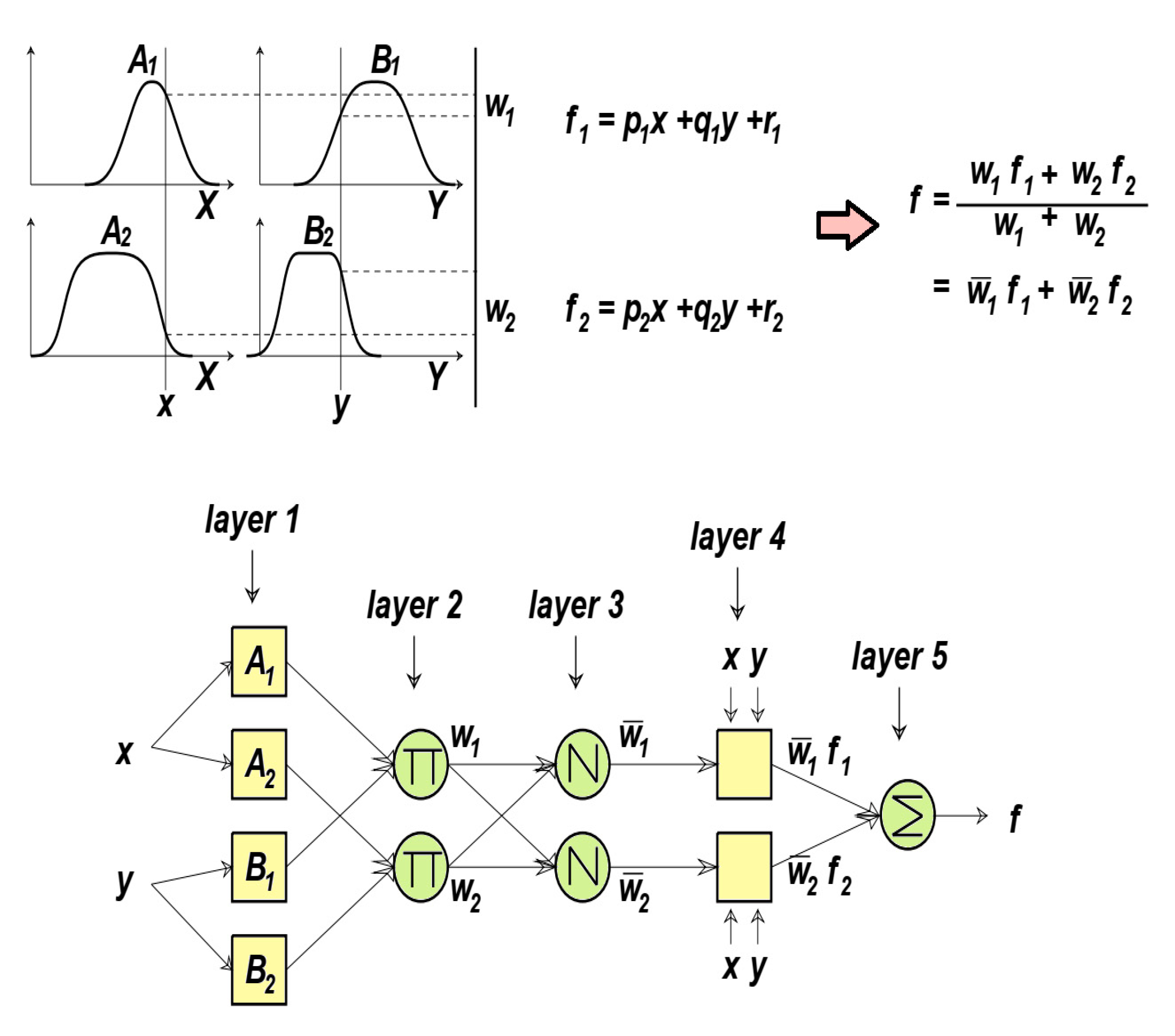
19] studied the deformation and failure behaviors of nugget, heat affected zone (HAZ), and corona bond in the RSW process of JSC980YL steel with the aim of a novel mini-peel test. They employed the Cockcroft-Latham ductile failure criterion for calibrating the fracture constants. Their results showed that TSS of nugget and corona bond were 37.6% higher and 5.8% lower, respectively, than that of the base material. Artificial intelligent approaches, such as fuzzy logic system (FIS) and artificial neural networks (ANN), have been utilized successfully to modelling of numerous process behavior over recent years. Artificial neural networks have attracted the attention of several investigators in numerous fields of industry and engineering [20,21]. Simplicity, extensive capacity, and high-speed processing are the main advantages of utilizing neural networks in comparison with conventional approaches. On the other hand, fuzzy logic system (FIS) is an accurate alternative to process modeling, especially for systems where mathematical modeling is very complex or even not possible [22]. Using fuzzy logic, the relationship between input and output variables can be provided for very complex systems. This method, using a combination of qualitative variables and mathematical operators, provides a more accurate decision-making process. The adaptive fuzzy-neuro inference system takes advantage of both neural network and fuzzy logic computation methods, so that in fuzzy modeling, the variables and parameters of the fuzzy system are computed adaptively by the utilization of artificial neural network. This method has been used successfully to predict the behavior of many complex engineering processes [23,24].
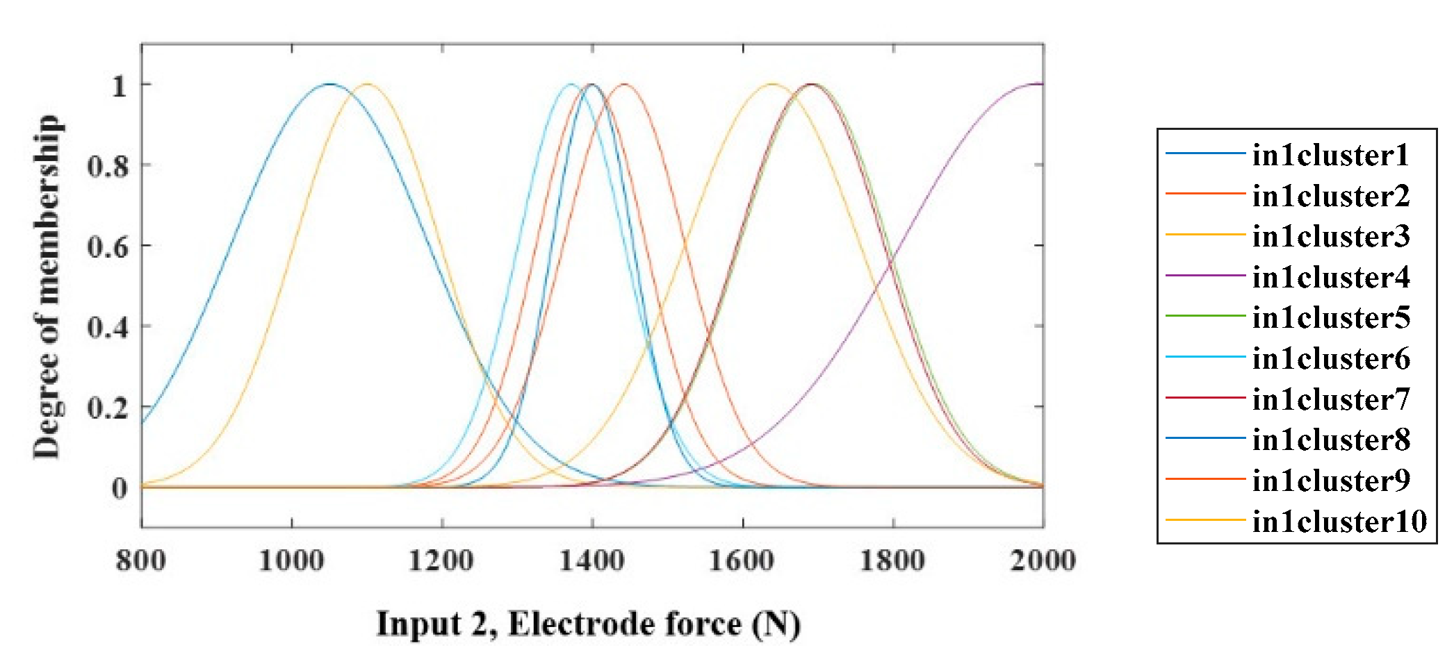
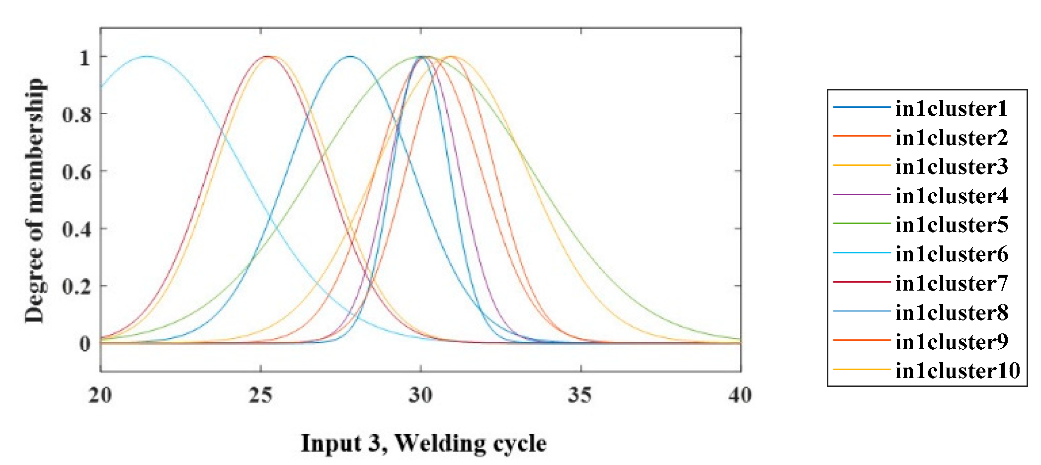
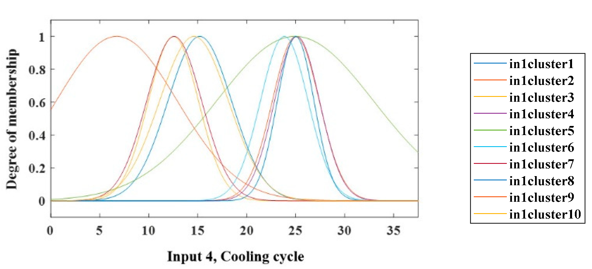
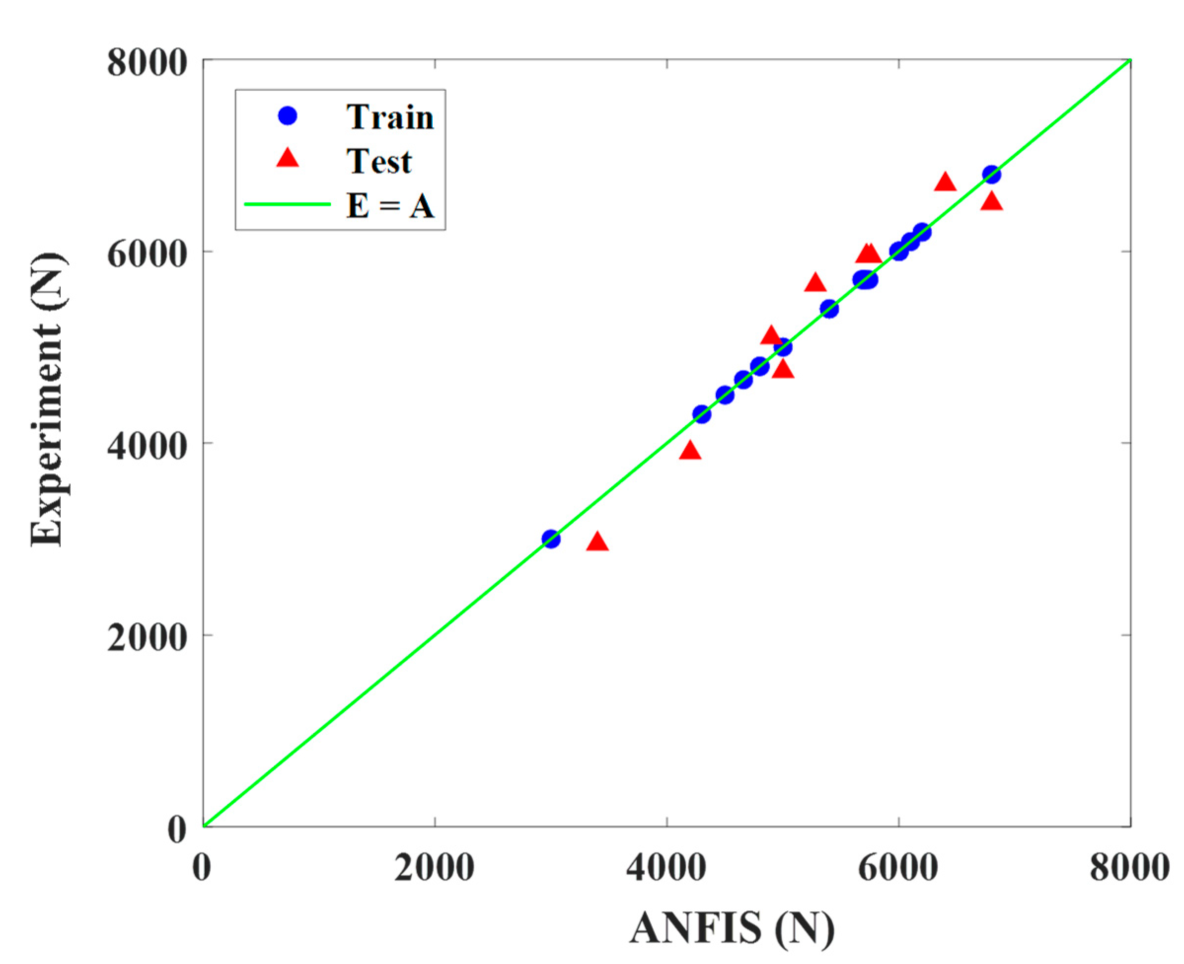
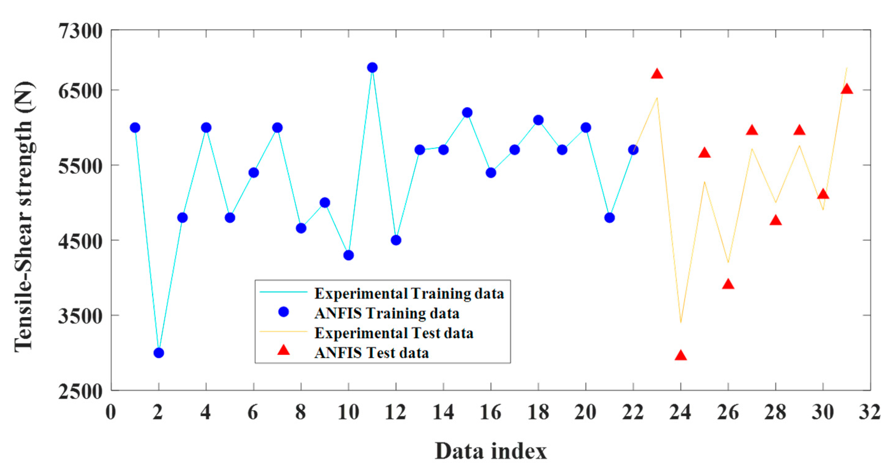
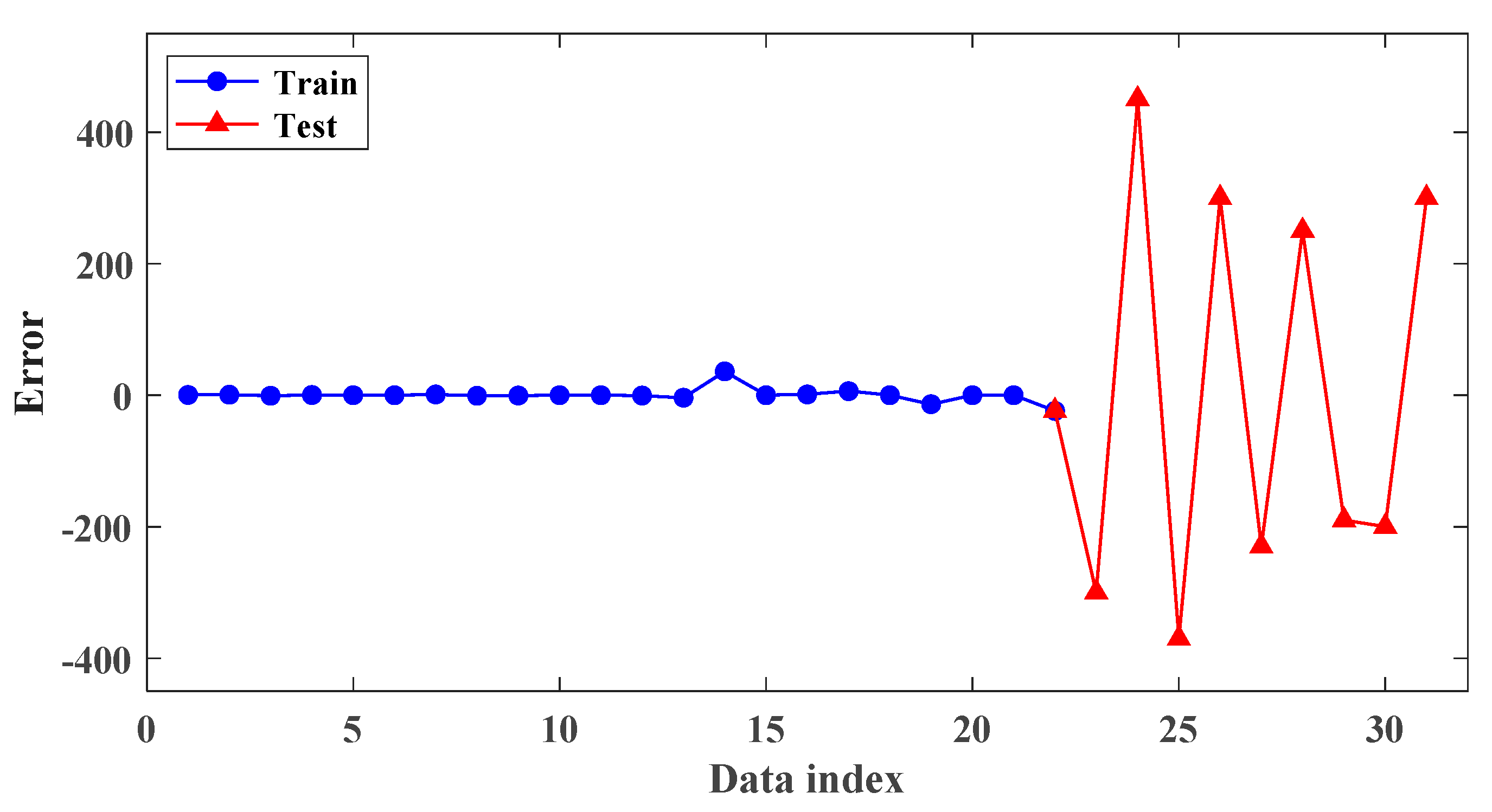
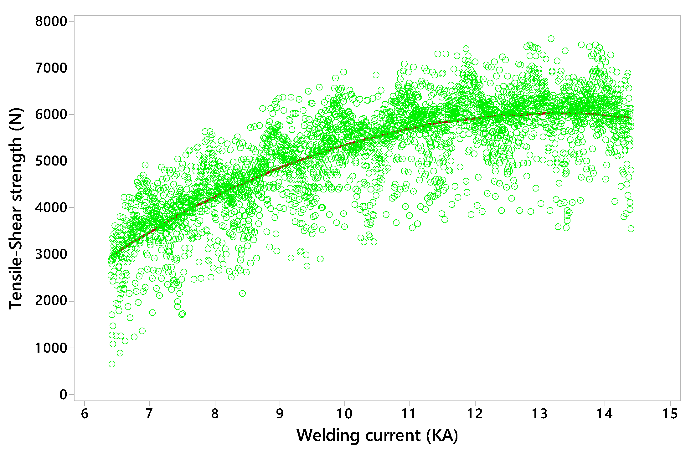
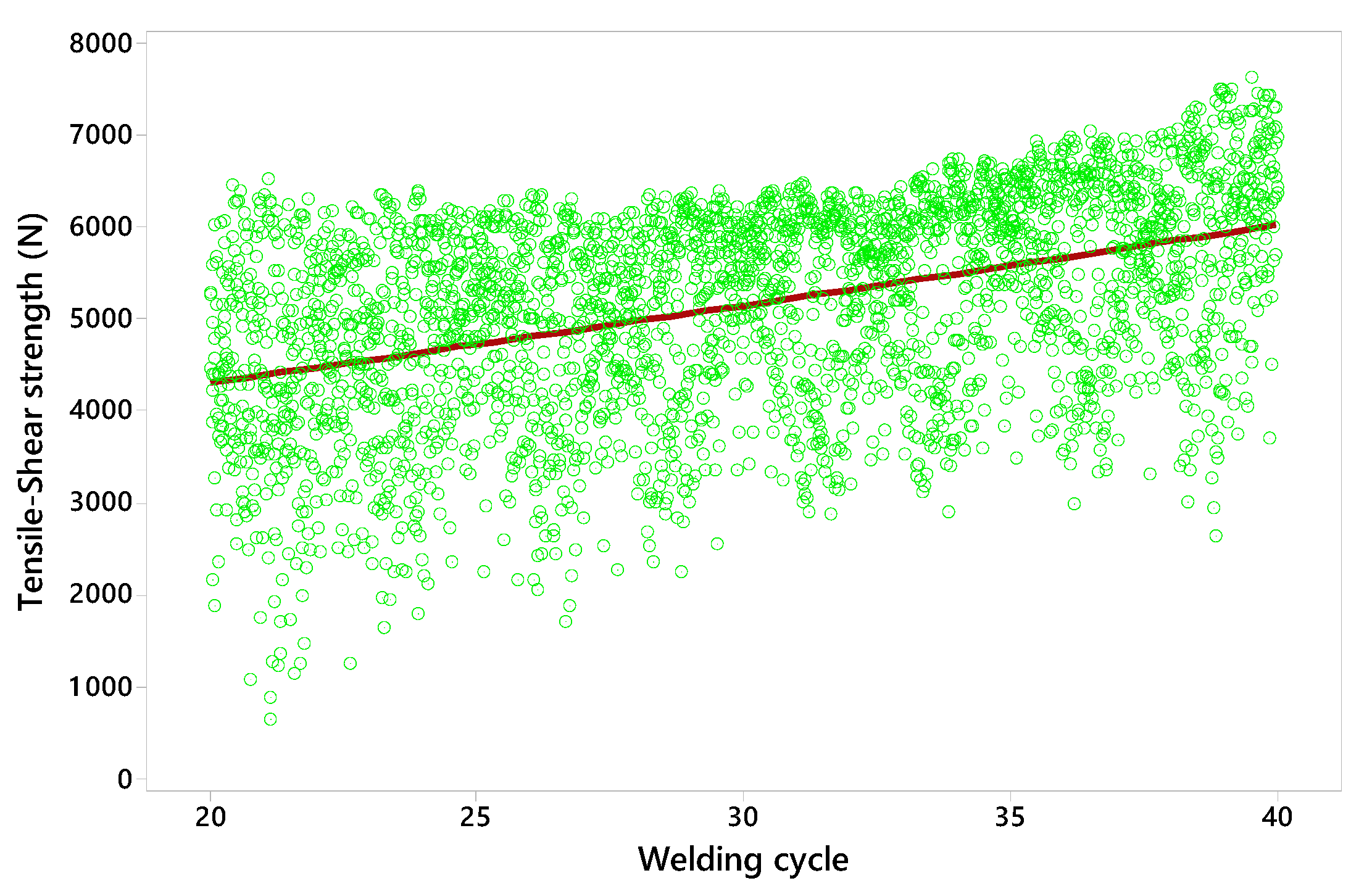
In this article, for the first time, ANFIS is used to model the effect of important parameters in the RSW such as welding current, welding cycle, cooling cycle, and electrode force in an attempt to predict the TSS of the welded joints. So far, this method has not been used to study the behavior and predict the output mentioned in RSW. It should be noted that one of the main challenges in the RSW is selecting the input parameters that leads to welded joint with maximum strength. Therefore, a complicated study with considering all the relations between input parameters and output TSS is necessary. To this aim, first using a standard central composite design (based on RSM) and also evaluating the accuracy of the experiments, the results of experiments have been used to train and test the fuzzy inference system. Also, to achieve the optimal structure of the ANFIS system, teaching-learning-based optimization (TLBO) algorithm has been used. Then, using the obtained results from ANFIS modeling as the input data for Sobel statistical sensitivity analysis method, the sensitivity of target response of RSW, i.e., TSS to changes in each of the input parameters is investigated.

2. Material and Method

2.1. Optimized Intelligent Modeling

2.1.1. Adaptive Neuro-Fuzzy Inference System (ANFIS)

The adaptive fuzzy-neural system uses two methods of fuzzy logic and neural network. Like former fuzzy inference systems, the adaptive neuro fuzzy inference system consists of two parts, the antecedent and the sequential, that are interconnected through a set of if-then rules. There are 5 different steps (layers) in the ANFIS network. One type of such network is the Takagi-Sugeno (TS) fuzzy model which has two inputs and one output, as displayed in Figure 1.
As displayed, ANFIS consists of two inputs (x and y), and one output (f) that are related by rules in the form of:
Rule one: If (x equals A 1 ) and (y equals B 1 ), then it becomes f 1 = p 1 x + q 1 y + r 1
Rule two: If (x equals A2) and (y equals B2), then it becomes f 2 = p 2 x + q 2 y + r 2
In this system, A i and B i are the fuzzy sets and F are the output of the system. Also, p i , q i , r i , are constants that are attained throughout the learning section. If the output of every single layer is considered to be O i j (output of node i in layer j), then the functions and operations of the distinct layers can be explained as:
Layer one: Every single node is identical to a fuzzy set and the output of that node in the corresponding set is identical to the degree of membership of the input variable, in this layer. The parameters of node specify the form of the membership function (MF) in the node. Since Gaussian MFs are used in present paper, it drives:
μ A i ( x ) = e 1 2 ( x c i σ i ) 2
where σ i and c i are the width and center of Gaussian MFs and x is the input value of each node.
Layer two: The values of the inputs of every single node are multiplied by each other and the rule firing strength is calculated as:
O i 2 = ω i = μ A i ( x ) μ B i ( y ) , i = 1 , 2
where μ A i is the degree of MF, x in A i and μ B i is the degree of MF y in B i .
Layer three: The nodes compute the associated weight of the rules, where ω i n is the normalized fire intensity of rule i.
O i 3 = ω i n = ω i ω 1 + ω 2       i = 1 , 2
Layer four: Fourth layer is known as the rule layer that is obtained by multiplying the normalized fire intensity (obtained in the third step) by the output of the TS fuzzy system.
O i 4 = ω i n f i = ω i n ( p i x + q i y + r i ) ,       i = 1 , 2
Layer five: Fifth layer, which is the last step, consists of a node where all the inputs are gathered together:
O i 5 = i = 1 2 ω i n f = ω 1 f 1 + ω 2 f 2 ω 1 + ω 2 ,       i = 1 , 2
Recently, various optimization techniques such as particle swarm algorithm and genetic algorithm have been used to increase the performance of the ANFIS system. Teaching-learning-based optimization (TLBO) is one of the newest and most efficient optimization methods that is utilized to optimize the ANFIS network in this article.

2.1.2. Teaching-Learning-Based Optimization (TLBO) Algorithm

The idea behind this algorithm is based on the impact a teacher has on students within a classroom where the teacher is the one who owns the best marks and has a higher rank than other students while being able to share his/her knowledge with other students. In general, the teaching and learning in a classroom are what inspires this algorithm. TLBO algorithm is divided into teacher and learner phase.
Teacher phase: In the first phase, the teacher who has more knowledge than others is selected from students. The teacher seeks to bring the class mean toward his/her average. In reality, however, this is not possible, i.e., not all students can reach the teacher level of knowledge, but they indeed change the average to a new value of M 2 . In this case, a new statistical community emerges whose average is M 2 and the teacher is T 2 . This process is repeated over the first phase until they develop a better or optimized population. In Figure 2a, T 1 is selected as the class teacher and tries to bring the average class level to his/her level.
The mathematical relationship for the teacher phase is described as
X n e w = X o l d + r ( X t e a c h e r T f × M e a n )
where r is a random vector with a value between 0 and 1 by which the success level of a student in comprehending something presented by the teacher is found. Also, T f shows the teacher success level with the values.
Learner phase: After the teacher phase, it is time for the learner phase. The learners can learn from each other and affect themselves. As such, their level can rise. According to Figure 2b, two learners are randomly selected from the population. The first learner ( X i ) wants to learn from the second learner ( X j ). Based on their mark, two cases are possible:
First case: If the grades of X i is worse than those of X j , while a low-grade learner is about to learn from another ( X j ) with better marks, then the corresponding mathematical relationship is expressed as
X i , n e w = X i + r ( X j X i )
where r is a random vector between 0 and 1, and determines the success level of the learner X i in comprehending what was described earlier.
Second case: If the grades of X i are better than those of X j , a condition similar to the previous case arises with the exception that X j learns from X i and the associated mathematical equation is in the form
X i , n e w = X i + r ( X i X j )
One should note that in both teacher and learner phases, a new objective function is developed after obtaining X i , n e w . If the new objective function is better than the older one, the learners’ data are updated; otherwise, the old data remains intact [25,26].

2.1.3. Sensitivity Analysis

Sensitivity analysis is a suitable utensil in evaluating the systems and extracting the influence of the input parameters on the output of the system for engineering problems. Sensitivity analysis describes the output uncertainty of the model and shows how this uncertainty is related to the inputs of the system [27].

2.1.4. Sobol Sensitivity Analysis

In this method for the defined model with function of Y = f(X) where Y is the output and X ( x 1 ، x 2 ، ، x n ) is the input parameter vector, the output variance of the model (V) is defined as the summation of each decomposed term as presented in Equation (9):
V ( Y ) = i = 1 n V i + i j n n V i j + + V 1 , , n      
where   V i is the first-order effect for each input factor [ x i ( V i = V [ E ( Y | x i ) ] ) and V ij = V [ E ( Y | x i ، x j ) ] V i V j ] to V 1 ،     ،   n shows the interaction of n factors. Sensitivity index is the ratio of each order variance to the total variance, so that S i = V i V is first order sensitivity index, S ij = V ij V is the second order sensitivity index and so forth. Total sensitivity index as the total effect of each parameter is defined as the summation of all orders of the sensitivity of the parameter can be computed as Equation (10) [27].
S T i = S i + i j S i j +                                      

2.2. Dissimilar RSW Process

In the present work, an austenitic stainless-steel sheet (AISI 304) and high carbon steel sheet (AISI 1060) with a thickness of 1mm are used. The chemical compositions of the welded materials are shown in Table 1.
A RSW machine with capacity of 150 KVA, controllable time, force, and current and pneumatic clamping mechanism is employed for the welding experiments. Conical Cu–Cr electrodes with the water circulating system and contact diameter of 5 mm are used for the RSW tests. Because of wear phenomenon in the RSW experiments, the diameter of electrodes was checked before starting of each welding experiment for controlling the electrode diameter. For this purpose, the electrodes were ground, cleaned, and measured to ensure that they had the desired diameter. Therefore, some electrodes with similar diameters were kept ready for RSW experiments. It should be noted that the dimensions of welded steel sheets are 150 mm (length) × 25 mm (width) × 1 mm (thickness). Also, the sheets with overlaps of 30 mm were placed between the centers of electrodes. The sheet surfaces were cleaned with a dry air jet. In order to determine the limits of process parameters for achieving a successful welded joint, some trial experiments were performed. Thus, the upper and lower limits of the process parameters such as welding current, welding cycle, electrode force and cooling cycle were determined and set in the microcomputer of the RSW machine.
Response surface methodology (RSM) is an optimization method that is widely used in welding processes for finding the optimum values of input process parameters in order to achieving the best response. It is a combine of mathematical and statistical methods for modeling and predicting the interested response based on optimized input process parameters. Based on RSM and design matrix (Table 2), 31 experiments were conducted. It should be noted that in the experiments the unit of welding and cooling times (Cycle) can be described as 1 Cycle = 1/50 of a second.
For increasing the accuracy and repeatability of the obtained results, each experiment was repeated and done three times and the average value of TSS has been reported.
The performed experiments are presented in Table 3.
In Figure 3, some of the welded specimens by RSW according to Table 3 experiments are presented.
In order to evaluate the strength of the welds, dissimilar RSW joints are prepared based on ISO 14273 for tensile shear tests. The TSS are performed in a Kpruf universal machine at room temperature and with cross-head speed of 1.0 mm/min. During tensile-shear test, different failure modes were observed, namely interfacial and pullout modes. Some of the joints with these failure modes are shown in Figure 4.
In Table 4, The TSS and failure modes after tensile-shear tests are presented for the RSW joints.

2.3. Analysis of Variance (ANOVA)

Based on the measured values for TSS of RSW joints of 31 experiments (Table 3), the results of analysis of variance are presented in Table 5. As it is seen in Table 5, the ANOVA shows the effect of input parameters as well as their interaction on TSS.
It is customary in engineering problems to consider a reliability of 95% sufficient. Therefore, the p-values less than 0.05 were considered to obtain effective parameters [28]. However, all of process parameters such as welding current, welding cycle, cooling cycle and electrode force, squares of welding current and cooling cycle and also interaction of welding cycle and cooling cycle influence the TSS of the spot welds. Considering R-sq = 93.10% and R-sq (adj) = 91% for TSS of RSW joints proves the acceptable accuracy of the proposed model. As R-sq approaches unity or 100%, the accuracy of the model increases and its anticipation accompanies with lower discrepancy.

3. Results and Discussion

3.1. The Results of TLBO-ANFIS System

In this study, 31 experimental data are employed for testing the network which including four inputs (the welding current, electrode force, welding cycle and cooling cycle) and one output (TSS). This data set is randomly divided into two subsets of 70% for network training and 30% for network testing. The number and parameters of input and output membership functions as well as fuzzy if-then rules are optimized using TLBO algorithm. Figure 5, Figure 6, Figure 7 and Figure 8 show the optimized Gaussian membership functions for the input variables.
In this section, certain graphical methods are used to evaluate the performance of the proposed model. Figure 9 simultaneously shows the actual data and the data approximated by the ANFIS model.
In these diagrams, the circular markers represent the data used in the training section and the triangular markers are for the network test data. The midline E = A is also a reference for determining the correctness of the obtained model. As can be seen, the accuracy of the ANFIS network is exceptional in estimating the data of the training and test section (circular and triangular markers are located close to the midline). Figure 10 shows the TSS for the actual and predicted data in the training and test section. In these diagrams, the lines in blue and orange are related to the experimental data of the training and test section, respectively. Circular and triangular markers are also related to the data predicted by the ANFIS network associated with training and test section, respectively. As observed, the ANFIS network corresponds to the data in the training section (circular markers match blue lines). The second part of the plots (i.e., the orange part) also shows that the network has been able to properly predict the data pertinent to the test section.
Figure 11 displays the error of the data related to the training and test section. It is observed that the error in the training section is less than the error in the test section.
To quantitatively investigate the obtained model, certain statistical criteria including root mean square error (RMSE), coefficient of determination ( R ), and mean absolute percentage error (MAPE) are employed. These criteria are expressed as
RMSE = 1 n × i = 1 n ( T A T P ) 2
R = i = 1 n [ ( T A T ¯ A ) ( T P T ¯ P ) ] [ i = 1 n ( T A T ¯ A ) 2 ] [ i = 1 n ( T P T ¯ P ) 2 ]
MAPE = 100 % n i = 1 n | T A T P T A |
where T A is the measured output for the ith sample, T P is the predicted output by the ANFIS network for the i-th sample, T ¯ A is the average of measured data and T ¯ P is the average of predicted data. To examine the model accuracy, the above-mentioned statistical criteria are separately calculated for the training and test section as listed in Table 6. Each of these criteria can represent the error of the obtained model, thus indicating the accuracy of predictions.
According to the values listed in Table 6, it is clear that the ANFIS network has been notably successful in predicting the TSS. RMSE values are very small. Indeed, these criteria alone are not enough for model evaluation. Next, the criteria R and MAPE which determine the amount of error relative to values of data are studied. The coefficient of determination, R, for TSS is close to 1 (above 0.9), indicating the high accuracy of the model. Moreover, the percentage error of MAPE in the training section is 0.08%. Furthermore, the percentage error of MAPE in the network test section is 5.87%. It can be seen here that the network error is relatively higher in the test section than in the training section. This is perfectly normal as the training section uses all the training data (70% of the entire data) and the model is obtained such that the network outputs are completely consistent with the used data. In contrast, the network test is based on the test data (the remaining 30% of the data) which have not been used in the network training section. Thus, due to errors in experimental results, such inconsistencies are to be expected in estimation.

3.2. Analysis of the Effects of Input Parameters on TSS Based on Sensitivity Analysis

3.2.1. The Effect of Welding Current

In Figure 12, the effect of welding current on TSS of dissimilar spot welds is shown. As can be seen, by increasing the welding current the TSS of the welded joints is increased. The reason is that the generated heat in the welding area and consequently the depth of penetration is increased with an increase in the welding current. However, this leads to an increase in the welded joint strength.

3.2.2. The Effect of Welding Cycle

In Figure 13, the effect of welding cycle on the TSS of the dissimilar welds is presented. It can be concluded from Figure 13 that the strength of the joints will be increased by increasing the welding cycle due to increase in the generated heat in welding zone and consequently increasing the spot area.

3.2.3. Effect of Electrode Force

As can be seen from Figure 14 the strength of the dissimilar welds is decreased by increasing the electrode force. This is since by increasing the electrode force, the electrical resistance in the welding area is decreased and consequently the heat energy in that area will be decreased that leads to decreasing the TSS.

3.2.4. Effect of Cooling Cycle

In Figure 15, the effect of cooling cycle on TSS of dissimilar joints can be seen. It is proved from Figure 15 that increasing in the cooling cycle leads to a decrease in weld strength. This is since increasing the cooling cycle leads to spreading the heat of welding area to the electrodes and this causes the electrodes to get more exposed to the wear.

3.3. Sobol Sensitivity Analysis of Tensile-Shear of RSW Joints

In Figure 16 the result of Sobol sensitivity analysis for the TSS of dissimilar joints is shown. The data in Figure 16 were achieved by Simlab software which simultaneously changes the input process parameters and evaluated their effects on output [27]. As can be seen from Figure 16, all the process parameters significantly influence the TSS of the welds. It also concluded that the parameters of welding current, welding cycle, cooling cycle, and electrode force have the greatest effect on the strength of the dissimilar joints, respectively.

4. Conclusions

In this paper, dissimilar RSW process of AISI 304 and AISI 1060 steel sheets was experimentally investigated. The effects of the main process parameters such as welding current, welding cycle, electrode force, and cooling cycle on the TSS of dissimilar RSW welded joints were modeled and predicted by adaptive neuro-fuzzy inference system (based on a teaching-learning-based optimization algorithm) and Sobol sensitivity analysis method. Then, modeling accuracy and effectiveness of each of the input RSW parameters were analyzed. It was demonstrated that the mathematical model could accurately anticipate the TSS of welded joints in the studied ranges of input parameters. The following can be highlighted as the findings of current study. The results showed that all of the process parameters such as welding current, welding cycle, cooling cycle, electrode force, the squares of the welding current and cooling cycle, and also the interaction of the welding cycle and cooling cycle influenced the TSS of the dissimilar spot welds. The results proved that by increasing the welding current the TSS of dissimilar welded joints was increased due to an increase in the generated heat in the welding area and, consequently, the depth of penetration. It was concluded that the strength of the dissimilar joints was increased by increasing the welding cycle due to increase in the generated heat in welding zone and consequently increasing the spot area. It was demonstrated that the strength of the dissimilar welds was decreased by increasing the electrode force due to decreasing the electrical resistance in the welding area and consequently the heat energy in that area. The results showed that increasing in the cooling cycle led to a decrease in dissimilar weld strength due to spreading the heat of welding area to the electrodes. In addition, increasing the cycle led to an increase in the risk of brittle microstructure in the welded joint. The analysis of the results showed that the resulting ANFIS network was very efficient for the present application and that by using this system it was possible to predict the values of TSS based on changes in process input variables. It can be seen here that coefficient of determination and mean absolute percentage error for the test section data is 0.96% and 5.87%, respectively, which indicates the high accuracy of the final model in approximating the desired outputs of the RSW process. The results of the Sobol sensitivity analysis for the TSS proved that all of process parameters were significantly influenced the TSS of the welds. It also concluded that the parameters of welding current, welding cycle, cooling cycle and electrode force had the greatest effect on the strength of the joints, respectively.

Author Contributions

Conceptualization, M.S.; methodology, M.S.; software, A.H.R.; validation, M.S.; formal analysis, R.J.A.d.S.; investigation, M.S.; resources, M.S. and A.H.R.; data curation, V.T.; writing—original draft preparation, M.S.; writing—review and editing, M.S. and R.J.A.d.S.; visualization, A.H.R. and V.T.; supervision, M.S. and R.J.A.d.S.; project administration, M.S.; funding acquisition, R.J.A.d.S. All authors have read and agreed to the published version of the manuscript.

Funding

Ricardo J. Alves de Sousa acknowledges grants UID/EMS/00481/2019-FCT and CENTRO01-0145- FEDER-022083-Centro2020, European Regional Development Fund (ERDF).

Institutional Review Board Statement

Not applicable.

Informed Consent Statement

Not applicable.

Data Availability Statement

Data available on request.

Conflicts of Interest

The authors declare no conflict of interest.

References

  1. Taufiqurrahman, I.; Ginta, T.L.; Mustapha, M. The effect of holding time on dissimilar resistance spot welding of stainless steel 316L and Ti6Al4V titanium alloy with aluminum interlayer. Mater. Today Proc. 2020, 46, 1563–1568. [Google Scholar] [CrossRef]
  2. Chen, G.; Xue, W.; Jia, Y.; Shen, S.; Liu, G. Microstructure and mechanical property of WC-10Co/RM80 steel dissimilar resistance spot welding joint. Mater. Sci. Eng. A 2020, 776, 139008. [Google Scholar] [CrossRef]
  3. Taufiqurrahman, I.; Ahmad, A.; Mustapha, M.; Lenggo Ginta, T.; Ady Farizan Haryoko, L.; Ahmed Shozib, I. The Effect of Welding Current and Electrode Force on the Heat Input, Weld Diameter, and Physical and Mechanical Properties of SS316L/Ti6Al4V Dissimilar Resistance Spot Welding with Aluminum Interlayer. Materials 2021, 14, 1129. [Google Scholar] [CrossRef] [PubMed]
  4. Jaber, H.; Kovacs, T. Dissimilar Resistance Spot Welding of Ferrite-Martensite Dual Phase Steel/low Carbon Steel: Phase Transformations and Mechanical Properties, Vehicle and Automotive Engineering; Springer: Miskolc, Hungary, 2018; pp. 709–718. [Google Scholar]
  5. Bemani, M.; Pouranvari, M. Microstructure and mechanical properties of dissimilar nickel-based superalloys resistance spot welds. Mater. Sci. Eng. A 2020, 773, 138825. [Google Scholar] [CrossRef]
  6. Noh, W.; Kim, W.; Yang, X.; Kang, M.; Lee, M.G.; Chung, K. Simple and effective failure analysis of dissimilar resistance spot welded advanced high strength steel sheets. Int. J. Mech. Sci. 2017, 121, 76–89. [Google Scholar] [CrossRef]
  7. Shi, L.; Kang, J.; Chen, X.; Haselhuhn, A.S.; Sigler, D.R.; Carlson, B.E. Carlson, Determination of fracture modes in novel aluminum-steel dissimilar resistance spot welds. Procedia Struct. Integr. 2019, 17, 355–362. [Google Scholar] [CrossRef]
  8. Rikka, V.R.; Sahu, S.R.; Roy, A.; Jana, S.N.; Sivaprahasam, D.; Prakash, R.; Gopalan, R.; Sundararajan, G. Tailoring micro resistance spot welding parameters for joining nickel tab to inner aluminium casing in a cylindrical lithium ion cell and its influence on the electrochemical performance. J. Manuf. Process. 2020, 49, 463–471. [Google Scholar] [CrossRef]
  9. Das, T.; Das, R.; Paul, J. Resistance spot welding of dissimilar AISI-1008 steel/Al-1100 alloy lap joints with a graphene interlayer. J. Manuf. Process. 2020, 53, 260–274. [Google Scholar] [CrossRef]
  10. Azhari-Saray, H.; Sarkari-Khorrami, M.; Nademi-Babahadi, A.; Kashani-Bozorg, S.F. Dissimilar resistance spot welding of 6061-T6 aluminum alloy/St-12 carbon steel using a high entropy alloy interlayer. Intermetallics 2020, 124, 106876. [Google Scholar] [CrossRef]
  11. Essoussi, H.; Elmouhri, S.; Ettaqi, S.; Essadiqi, E. Microstructure and mechanical performance of resistance spot welding of AISI 304 stainless steel and AISI 1000 series steel. Procedia Manuf. 2019, 32, 872–876. [Google Scholar] [CrossRef]
  12. Neystani, R.; Beidokhti, B.; Amelzadeh, M. Fabrication of dissimilar Fe-Cu-C powder metallurgy compact/steel joint using the optimized resistance spot welding. J. Manuf. Process. 2019, 43, 200–206. [Google Scholar] [CrossRef]
  13. Valera, J.; Miguel, V.; Martínez, A.; Naranjo, J.; Cañas, M. Optimization of electrical parameters in Resistance Spot Welding of dissimilar joints of micro-alloyed steels TRIP sheets. Procedia Manuf. 2017, 13, 291–298. [Google Scholar] [CrossRef]
  14. Vignesh, K.; Perumal, A.E.; Velmurugan, P. Optimization of resistance spot welding process parameters and microstructural examination for dissimilar welding of AISI 316L austenitic stainless steel and 2205 duplex stainless steel. Int. J. Adv. Manuf. Technol. 2017, 93, 455–465. [Google Scholar] [CrossRef]
  15. Mansor, M.S.M.; Yusof, F.; Ariga, T.; Miyashita, Y. Microstructure and mechanical properties of micro-resistance spot welding between stainless steel 316L and Ti-6Al-4V. Int. J. Adv. Manuf. Technol. 2018, 96, 2567–2581. [Google Scholar] [CrossRef]
  16. Anijdan, S.M.; Sabzi, M.; Ghobeiti-Hasab, M.; Roshan-Ghiyas, A. Optimization of spot welding process parameters in dissimilar joint of dual phase steel DP600 and AISI 304 stainless steel to achieve the highest level of shear-tensile strength. Mater. Sci. Eng. A 2018, 726, 120–125. [Google Scholar] [CrossRef]
  17. Chen, F.; Wang, Y.; Sun, S.; Ma, Z.; Huang, X. Multi-objective optimization of mechanical quality and stability during micro resistance spot welding. Int. J. Adv. Manuf. Technol. 2019, 101, 1903–1913. [Google Scholar] [CrossRef]
  18. Mirzaei, F.; Ghorbani, H.; Kolahan, F. Numerical modeling and optimization of joint strength in resistance spot welding of galvanized steel sheets. Int. J. Adv. Manuf. Technol. 2017, 92, 3489–3501. [Google Scholar] [CrossRef]
  19. Ma, Y.; Takikawa, A.; Nakanishi, J.; Doira, K.; Shimizu, T.; Lu, Y.; Ma, N. Measurement of local material properties and failure analysis of resistance spot welds of advanced high-strength steel sheets. Mater. Des. 2021, 201, 109505. [Google Scholar] [CrossRef]
  20. Sureshkumar, B.; Vijayan, V.; Dinesh, S.; Rajaguru, K. Neural network modeling for face milling operation. Int. J. Veh. Struct. Syst. 2019, 11, 214–219. [Google Scholar] [CrossRef]
  21. Radha Krishnan, B.; Vijayan, V.; Parameshwaran Pillai, T.; Sathish, T. Influence of surface roughness in turning process—An analysis using artificial neural network. Trans. Can. Soc. Mech. Eng. 2019, 43, 509–514. [Google Scholar] [CrossRef]
  22. Vukman, J.; Lukic, D.; Borojevic, S.; Rodic, D.; Milosevic, M. Application of Fuzzy Logic in the Analysis of Surface Roughness of Thin-Walled Aluminum Parts. Int. J. Precis. Eng. Manuf. 2020, 21, 91–102. [Google Scholar] [CrossRef]
  23. Dambatta, Y.S.; Sayuti, M.; Sarhan, A.A.; Ab Shukor, H.B.; binti Derahman, N.A.; Manladan, S.M. Prediction of specific grinding forces and surface roughness in machining of AL6061-T6 alloy using ANFIS technique. Ind. Lubr. Tribol. 2019, 71, 309–317. [Google Scholar] [CrossRef]
  24. Xu, L.; Huang, C.; Li, C.; Wang, J.; Liu, H.; Wang, X. Estimation of tool wear and optimization of cutting parameters based on novel ANFIS-PSO method toward intelligent machining. J. Intell. Manuf. 2021, 32, 77–90. [Google Scholar] [CrossRef]
  25. Rao, R.V.; Savsani, V.J.; Vakharia, D.P. Teaching–Learning-based optimization: A novel method for constrained mechanical design optimization problems. Comput.-Aided Des. 2011, 43, 303–315. [Google Scholar] [CrossRef]
  26. Rao, R.V.; Savsani, V.J.; Vakharia, D.P. Teaching–Learning-based optimization: An optimization method for continuous non-linear large scale problems. Inf. Sci. 2012, 183, 1–15. [Google Scholar] [CrossRef]
  27. Sobol, I.M. Sensitivity analysis for non-linear mathematical models. Math. Model. Comput. Exp. 1993, 1, 407–414. [Google Scholar]
  28. Montgomery, D.C. Design and Analysis of Experiments; John Wiley & Sons: Hoboken, NJ, USA, 2017. [Google Scholar]
Figure 1. ANFIS structure.
Metals 11 01324 g001
Figure 2. (a) Teacher phase, (b) Learner phase.
Metals 11 01324 g002
Figure 3. Some of the welded specimens by RSW according to Table 3 experiments.
Metals 11 01324 g003
Figure 4. Two failure modes after tensile shear tests: (a) interfacial mode and (b) pullout mode.
Metals 11 01324 g004
Figure 5. Optimized membership functions for the welding current.
Metals 11 01324 g005
Figure 6. Optimized membership functions for the electrode force.
Metals 11 01324 g006
Figure 7. Optimized membership functions for the welding cycle.
Metals 11 01324 g007
Figure 8. Optimized membership functions for the cooling cycle.
Metals 11 01324 g008
Figure 9. Comparison between experimental and predicted data.
Metals 11 01324 g009
Figure 10. Difference between experimental and predicted data.
Metals 11 01324 g010
Figure 11. Error of experimental and predicted data.
Metals 11 01324 g011
Figure 12. Effect of welding current on TSS of spot welds.
Metals 11 01324 g012
Figure 13. Effect of welding cycle on TSS of spot welds.
Metals 11 01324 g013
Figure 14. Effect of electrode force on TSS of spot welds.
Metals 11 01324 g014
Figure 15. Effect of cooling cycle on TSS of spot welds.
Metals 11 01324 g015
Figure 16. The diagram of effectiveness of input parameters on TSS of RSW joints.
Metals 11 01324 g016
Table 1. Chemical composition (%) of the AISI 304 and AISI 1060 stainless steels.
ElementsCSiMnPSCrMoNi
AISI 10600.620.420.71≤0.03≤0.050.210.08-
AISI 3040.120.426.2≤0.05≤0.0317.1-4.7
Table 2. Coded and actual values of parameters for the RSW investigations.
ParameterLimits
−2−10+1+2
Welding current (KA)6.48.410.412.414.4
Welding cycle (cycle)2025303540
Cooling cycle (cycle)012.52537.550
Electrode force (N)8001100140017002000
Table 3. Design layout of RSW experiments based on response surface methodology.
SchemeWelding Current (KA)Electrode Force (N)Welding CycleCooling Cycle
18.411002512.5
212.411002512.5
38.417002512.5
412.417002512.5
58.411003512.5
612.411003512.5
78.417003512.5
812.417003512.5
98.411002537.5
1012.411002537.5
118.417002537.5
1212.417002537.5
138.411003537.5
1412.411003537.5
158.417003537.5
1612.417003537.5
176.414003025.0
1814.414003025.0
1910.48003025.0
2010.420003025.0
2110.414002025.0
2210.414004025.0
2310.41400300.00
2410.414003050.0
2510.414003025.0
2610.414003025.0
2710.414003025.0
2810.414003025.0
2910.414003025.0
3010.414003025.0
3110.414003025.0
Table 4. The values of TSS and failure modes for the RSW joints.
SampleTensile-Shear Strength (N)Failure Mode
14280Interfacial
26100Pullout
34720Interfacial
46050Pullout
54740Interfacial
66830Pullout
74770Interfacial
86048Pullout
94150Interfacial
105300Pullout
113450Interfacial
124810Pullout
135090Pullout
146340Pullout
155300Pullout
166900Pullout
172940Interfacial
186030Pullout
196037Pullout
205100Pullout
214600Interfcial
225910Pullout
235300Pullout
245000Pullout
255740Pullout
265680Pullout
275700Pullout
285660Pullout
295700Pullout
305730Pullout
315770Pullout
Table 5. ANOVA for TSS of dissimilar joints of AISI 304 and AISI 1060 steels after RSW process.
SourceDFAdj SSAdj MSf-Valuep-Value
Model721907927312970444.360.000
Linear418475843461896165.470.000
Welding current (KA)11323283513232835187.550.000
Electrode force (N)13802683802685.390.029
Welding cycle14387005438700562.180.000
Cooling cycle14757354757356.740.016
Square22121631106081515.040.000
Welding current (KA) × Welding current (KA)11960822196082227.790.000
Cooling cycle × Cooling cycle12727942727943.870.061
2-Way Interaction11310453131045318.570.000
Welding cycle × Cooling cycle11310453131045318.570.000
Error23162275770555--
Lack-of-Fit17161798595176119.680.000
Pure Error64771795--
Total3023530684---
Table 6. Different criteria (RSME and MAPE) for TSS modeling.
RMSE R MAPE (%)
T e n s i l e S h e a r   s t r e n g t h Training9.820.990.08
Test2980.965.87
Publisher’s Note: MDPI stays neutral with regard to jurisdictional claims in published maps and institutional affiliations.

