Article

Supersonic Shrouding Methane Mixtures for Supersonic Combustion Coherent Jets

1
Key Laboratory of Fluid Interaction with Material, University of Science and Technology Beijing, Beijing 100083, China
2
National Center for Materials Service Safety, University of Science and Technology Beijing, Beijing 100083, China
3
School of Metallurgical and Ecological Engineering, University of Science and Technology Beijing, Beijing 100083, China
4
School of Mechanical Engineering, University of Science and Technology Beijing, Beijing 100083, China
*
Author to whom correspondence should be addressed.
Metals 2023, 13(1), 123; https://doi.org/10.3390/met13010123
Submission received: 17 November 2022 / Revised: 25 December 2022 / Accepted: 5 January 2023 / Published: 7 January 2023
(This article belongs to the Special Issue Clean Ironmaking and Steelmaking Processes)

Abstract

:
A coherent jet oxygen supply plays a key role in the process of electric arc furnace steelmaking: it provides the necessary oxygen for the smelting of molten steel and promotes the flow of the molten pool. Compared with coherent jets in current use, the supersonic combustion coherent jet shrouded in supersonic methane gas could improve the impact capacity and stirring intensity of the molten pool. In order to reduce the smelting cost, the characteristics of the supersonic combustion coherent jet shrouding the supersonic methane and nitrogen mixtures must be studied. Computational fluid dynamics software is used to simulate the supersonic combustion coherent jet under various methane–nitrogen mixing conditions. The six-component combustion mechanism of methane and the Eddy Dissipation Concept combustion reaction model are selected. In agreement with thermal experiments, the simulation results show that the inclusion of a small amount of nitrogen has little effect on the combustion of supersonic shrouding methane gas. However, as the nitrogen content increases, the combustion region of supersonic shrouding gas becomes shorter in length, resulting in decreases in the lengths of the high-temperature, low-density region, and the high-turbulence-intensity region. These effects weaken the ability of the shrouding gas to envelop the main oxygen jet. The potential core length of the main oxygen jet decreases significantly; this decrease first accelerates and then decelerates. These results demonstrate the feasibility of including a small amount of nitrogen (about 10 wt%) in the supersonic shrouding methane gas without substantial negative impacts on the characteristics of the supersonic combustion coherent jet.

1. Introduction

As the global production of scrap steel increases, the proportion of electric arc furnace (EAF) steelmaking continues to increase due to its flexibility and low emissions [1,2]. Supersonic jet oxygen supply technology provides the necessary oxygen for molten steel smelting, and the oxidation reaction rate is accelerated due to the stirring effect of a high-speed oxygen jet on the molten pool [3,4,5]. However, as EAF service time continues to extend, the coherent jets in current use cannot meet the needs of the stirring strength of the molten pool due to the decrease in the molten pool level in the middle and later stages of the EAF. Thus, the search for ways to effectively improve the impact capacity of the jet on the molten pool has become a popular topic in recent years [6,7,8,9,10]. Sumi et al. [11,12] and Klioutchnikov et al. [13] studied the flow characteristic of coherent jet for high-temperature and low-pressure environments combining simulation and experiment methods. Low density effect under high-temperature and low-pressure environments, which extends the velocity potential core length and slows the main oxygen jet velocity decay. Wei et al. [14] studied the penetration depths of a supersonic jet and a coherent jet into the molten pool. Because of the envelope of the high-temperature flame generated by shrouding flue gas, the volume of the impact zone was much larger in the coherent jet than in the conventional supersonic jet. Alam et al. [15,16,17] studied the characteristics of a coherent jet under various shrouding gas parameters and analyzed the effect of the shrouding gas on the main oxygen jet velocity and penetration depth. The depth of penetration and liquid free surface velocity were observed to increase as the shrouding gas flow rate increased. Li et al. [18] proposed enhancing the impact ability of the coherent jet by mixing high-temperature water vapor into the main oxygen jet. They further studied the velocity and temperature distributions of the main oxygen jet under various mixing ratios of oxygen and water vapor. Their results showed that as the ratio of high-temperature water vapor increased, the velocity of the main oxygen jet increased, while the potential core length of the main oxygen jet decreased. Tang et al. [19,20] and Cheng et al. [21] studied the influence of shrouding fuel gas on the main oxygen jet length under blast furnace gas, natural gas, and coke oven gas conditions through numerical simulations. Their results indicated that the potential core length of the main oxygen jet could be increased by using a shrouding fuel of low molecular weight or gaseous density. It can be seen from the above research that the high-temperature flame generated by the shrouding fuel gas can effectively reduce the velocity attenuation of the main oxygen jet. Parameters such as temperature, density, and velocity in the high-temperature flame region exert key influences on the characteristics of the coherent jet. Meanwhile, the author has previously proposed that the supersonic combustion coherent jet shrouding the supersonic fuel gas has an even stronger impact ability on the main oxygen jet because it can produce a larger combustion region to envelop the main oxygen jet [22,23]. The above research results show that the characteristics of the coherent jet are directly affected by the parameters such as the type, temperature, and pressure of shrouding gas. Considering the price and safety of nitrogen, it is worth studying whether the smelting cost can be reduced by mixing nitrogen into the shrouding gas flow. However, there is a lack of research on supersonic combustion coherent jet shrouding the supersonic methane and nitrogen mixtures. Therefore, in order to provide data support to promote the development of supersonic combustion coherent jet technology and reduce smelting costs, it is necessary to study the mixture of the supersonic shrouding methane gas with nitrogen and obtain the influence of the nitrogen mixing ratio on the temperature and Mach number distribution of the main oxygen jet.

2. Combustion Experiments and Numerical Simulations

2.1. Combustion Experiments

Figure 1 shows the structure diagram of the supersonic combustion coherent jet nozzle in this study. Unlike coherent jet nozzles in current use, the shrouding gas nozzle is a Laval nozzle, not a linear nozzle. In this paper, the exit Mach numbers of the main oxygen nozzle and shrouding gas nozzle are all 2.0. The supersonic combustion coherent jet nozzle is a double-layer structure. The main oxygen jet flows in the inner pipeline, and the shrouding gas flows in the outer annular pipe, as shown in Figure 1. The exit diameter De of the main oxygen jet is 30.66 mm.
Figure 2 shows a schematic of the combustion experimental apparatus. High-pressure nitrogen and methane are mixed in specified proportions and loaded into the cylinder. The methane mixture and oxygen are connected to the supersonic combustion coherent jet nozzle, and kerosene and oxygen are connected to the heating burner. The function of the heating burner is to raise the furnace temperature to a specified temperature to simulate the high-temperature environment of the EAF. The thermocouple is used to measure the temperature of the high-temperature furnace. When the high-temperature furnace reaches the specified temperature, the supersonic combustion coherent jet experiment is initiated and the supersonic combustion coherent jet is ignited after entering the high temperature furnace. The water-cooled pitot tube is used to measure the pressure of main oxygen jet. During the experiment process, the pitot tube does not change its dimensions and it could move along the nozzle axis the through the shift equipment to measure the main oxygen jet pressure at various positions. The oxygen and kerosene burner has been working in the experiment, and the experiment is stopped when the pressure sensor obtains stable pressure of the main oxygen jet. Considering that the thermocouple is disturbed by the high temperature furnace during the measurement of the coherent jet temperature, which affects the accuracy of the measurement results, the coherent jet temperature is not measured in this paper. The Mach number of main oxygen jet is obtained by theoretical calculation to verify the Mach number obtained by numerical simulation, and then the accuracy of the numerical simulation results is illustrated. The Mach number Ma of the main oxygen jet was calculated as the following [24]:
M a = 2 κ 1 [ ( P 0 p ) ( κ 1 ) κ 1 ]
where P0 is the total pressures of the main oxygen jet (in Pa), p is the static pressures of the main oxygen jet (in Pa), and κ is the heat capacity ratio.

2.2. Numerical Simulation

The numerical simulation of the flow field is calculated by solving the Reynolds-averaged Navier–Stokes equations [25] in this study. Furthermore, the averaged mass, momentum, and energy equations are as follows:
ρ t + x i ( ρ u i ) = 0
t ( ρ u i ) + x j ( ρ u i u j ) = p x j + x j [ μ ( u i x j + u j x i 2 3 δ i j u k x k ) ] + x j ( ρ u i u j ¯ )
t ( ρ E ) + x i [ u i ( ρ E + p ) ] = x j ( k e f f T x j + u i ( τ i j ) e f f ) + S h
and
t ( ρ E ) + x i [ u i ( ρ E + p ) ] = x j ( k e f f T x j + u i ( τ i j ) e f f ) + S h
where ρ is the density of the fluid (in kg·m−3); u is the velocity (in m·s−1)and the i, j, and k represent directions; P is the static pressure (in Pa); μ is the molecular viscosity (in Pa·s) and μt is the turbulence viscosity; k is the turbulent kinetic energy (in m2·s−2); E is the total energy (in J); keff is the effective thermal conductivity (in W·m−1·K−1); T is the temperature (in K); τij is the viscous stress (in N·s−2); and Sh is the energy source.
Compared with other turbulence models, the kω shear-stress transport model is more suitable for the simulation of the coherent jets [26]. The kω shear-stress transport model used the kω model in the near-wall region and was the k–ε model in the far field [27] to obtain the accurate solution of flow field parameters. Previous research results [9,28] show that the kω shear-stress transport model is suitable for simulating supersonic jets. The kω shear-stress transport equations are as follows:
t ( ρ k ) + x i ( ρ k u i ) = x j [ Γ k k x j ] + G k Y k + S k
and
t ( ρ ω ) + x i ( ρ ω u i ) = x j [ Γ ω ω x j ] + G ω Y ω + D ω + S ω
where Gk is the generation of turbulence kinetic energy due to the mean velocity gradients, (in J); Gω is the turbulent kinetic energy generated due to ω (in J); Yk is the k turbulence dissipations (in J); Yω is the ω turbulence dissipations (in J); Γk is the effective diffusivities of k, Γω is the effective diffusivities of ω; Dω is the damping cross-diffusion phase; and Sk and Sω are source phases.

2.3. Simulation Details

Figure 3 shows the calculation model of the supersonic combustion coherent jet described herein. The supersonic combustion coherent jet nozzle is on the left side of the model. The main oxygen jet and shrouding gas enter the computational domain in here. The middle of the calculation model is the jet-spreading region and its length and width are 100 De and 20 De, respectively. The axisymmetric swirl model is selected to reduce the amount of computation. In order to improve the accuracy of calculation, the second order upwind scheme is selected in this study. The six-component Chemkin combustion mechanism of methane and the Eddy Dissipation Concept combustion reaction model are used to obtain accurate temperature field distribution. The residuals of calculation results are set to <106 to ensure the convergence of the calculation results. The specific parameters of the boundary conditions are shown in Table 1.

2.4. Grid Independence Test

Grid quality is a key factor affecting the accuracy of the calculation results. An appropriate number of grids can reduce the computation time and obtain accurate simulation results. Therefore, a grid independence test should be conducted before formal calculation. In order to quickly verify whether the selection of the calculation grid is reasonable, a simple computational model is built based on geometric model shown in Figure 3. The pure nitrogen is selected as the shrouding gas. This calculation case is relatively simple, but this does not affect the choice of computation grid. Therefore, a numerical simulation of a supersonic combustion coherent jet with the shrouding nitrogen gas was carried out. Figure 4 shows the axial Mach number distribution of the main oxygen jet for the different density grids. It can be seen from figure that the Mach number distribution trend of the main oxygen jet is the same for different density grids. The Mach number distribution for low-density grid is different from the other two density grids, while the computations of the medium-density grid and high-density grid are basically consistent. Therefore, it is appropriate to select medium density mesh as computational mesh in order to reduce the required computation time without sacrificing model accuracy.

3. Results and Discussion

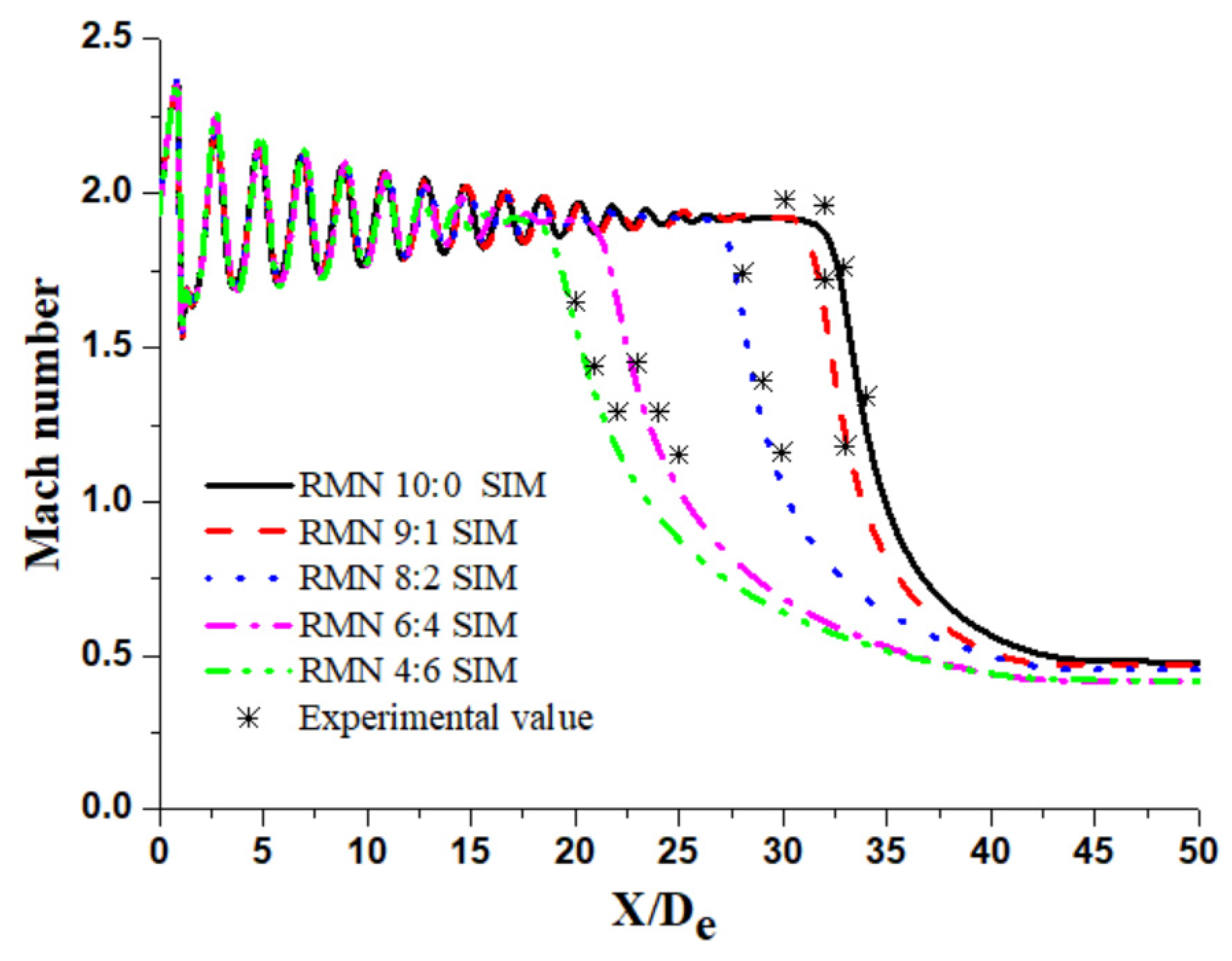
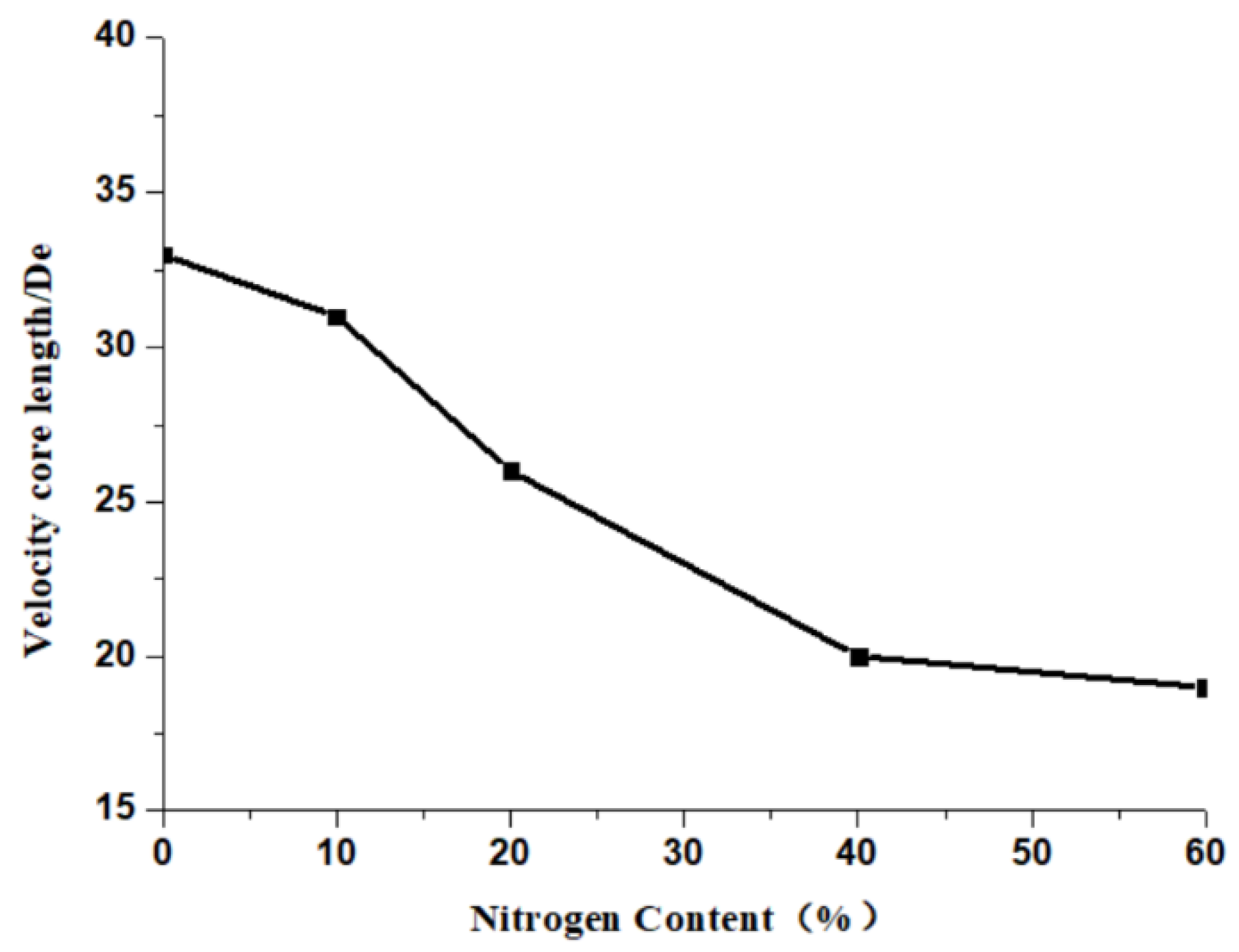
3.1. Mach Number Distribution

Figure 5 shows the axis Mach number for the main oxygen jet under various ratios of methane to nitrogen (RMN). In order to describe the potential core length of the main oxygen jet more reasonably, the dimensionless X/De is used as the ordinate in place of the absolute length. The solid line in the figure is the numerical simulation value, and the asterisk is the experimental value. It can be seen that the Mach number distribution trend of the main oxygen jet is similar across various RMN conditions. Repeated fluctuations in the main oxygen jet occur after exiting the nozzle. The high-temperature flame changes the nozzle exit pressure, resulting in a mismatch between the actual nozzle exit pressure and the nozzle design inlet pressure. After leaving the nozzle exit, the high-speed oxygen jet needs to adjust its pressure through the shock wave to maintain balance with the ambient pressure. As the adjustment continues, the pressure change becomes weaker and weaker. The velocity core length of the main oxygen jet is the distance from the nozzle exit at which the jet velocity begins to drop sharply. The velocity core length of the main oxygen jet is the greatest, at about 33 De, when the RMN of the shrouding gas is 10:0 (that is, the shrouding gas is pure methane). When the RMN of the shrouding gas is reduced to 9:1, 8:2, 6:4, or 4:6, the velocity core length of the main oxygen jet is reduced to 31 De, 26 De, 20 De, or 19 De, respectively. That is to say, as the nitrogen content increases, the velocity core length decreases monotonically.
Due to the presence of nitrogen in the supersonic shrouding methane gas, the combustion area of the supersonic shrouding gas is reduced, thus weakening both the envelope of the flame on the main oxygen jet and the ability to inhibit supersonic jet velocity attenuation. In order to further reveal the influence of the shrouding gas RMN on the main oxygen jet, the relationship between the shrouding gas RMN and the velocity core length of the main oxygen jet was examined. The velocity core length of main oxygen jet under different RMN conditions is obtained from Figure 5 and placed on the same chart to draw Figure 6. It can more intuitively compare the influence of nitrogen mixing ratio on the velocity core length of main oxygen jet. Between a shrouding gas RMN of 10:0 and a shrouding gas RMN of 9:1, the nitrogen content increases by 10%, just as between a shrouding gas RMN of 9:1 and a shrouding gas RMN of 8:2, but the corresponding changes in the velocity core length of the main oxygen jet differ. When the nitrogen content increases from 0 to 10%, the velocity core length is reduced by only 1 De, a reduction of 3%, but when the nitrogen content continues to increase from 10% to 20%, the velocity core length is reduced by 5 De, a reduction of 16%. This finding shows the nonlinearity of the effect of the shrouding gas nitrogen content on the length of the velocity core length. When a small amount of nitrogen is mixed in methane, it has little effect on methane combustion, but as the nitrogen content continues to increase, it begins to strongly affect the combustion of methane, and the velocity core length of the main oxygen jet becomes greatly reduced.
Similarly, when the RMN of the shrouding gas is 8:2, 6:4, and 4:6, the nitrogen content increases by 20% sequentially, but the corresponding changes in the velocity core length of the jet differ. When the nitrogen content increases from 20% to 40%, the velocity core length decreases by 6 De, a reduction of 23%, but when the nitrogen content in the shrouding gas increases from 40% to 60%, the velocity core length decreases by only 1 De, a reduction of 5%. The numerical simulation results are in good agreement with the experimental results, never exceeding 10%. However, some of these differences between numerical simulation and experimental results are caused by the measurement error in process of the experiment, and some are caused by the turbulence model, discrete method, combustion mechanism, and the method of meshing in the process of numerical simulation [29]. However, the differences caused by these reasons are very small and will not affect the analysis of the final results. The Mach number of main oxygen jet simulated is in good agreement with the experimental measurements. Therefore, it can be reasonably inferred that other numerical simulation results such as jet temperature, density, and turbulence distribution are also correct.
Next, the velocity distribution of the main oxygen jet along the radial direction for various shrouding gas RMNs was studied. The half-jet width (R1/2) is the radial distance at which the jet velocity is half the axial velocity. The half-jet widths of the main oxygen jet under different RMN conditions are shown in Figure 7. The R1/2 distribution for the main oxygen jet is similar across conditions. Figure 7 shows that the R1/2 distributions can be classified into three stages. First, the half-jet width of the main oxygen jet increases rapidly after leaving the nozzle exit. Then, the half-jet width increases at a slower rate. Finally, the half-jet width again increases at a higher rate. This pattern is due to the sharp increase in flow velocity in the boundary layer near the wall of the main oxygen jet nozzle due to the driving effect of supersonic shrouding gas. Therefore, the half-jet width of the main oxygen jet increases rapidly in the radial direction in the first stage of jet expansion. In the second stage, due to the envelope effect of the high-temperature region of supersonic shrouding gas combustion, the expansion of the main oxygen jet in the radial direction is greatly inhibited, so the half-jet width of the main oxygen jet increases at a lower speed. With the oxygen jet moving forward, the main oxygen jet then breaks away from the high-temperature flame region and quickly mixes with gas in the external environment, resulting in a rapid increase in the half-jet width. The position of the junction of the second and third stages of half-jet width is basically the same as the position at which the main oxygen jet Mach number decreases rapidly in Figure 5. In addition, as the nitrogen content in the shrouding gas increases, the slow-growth region length of the half-jet width continues to decrease in length, from 33 De under the condition of RMN = 10:0 to 19 De under the condition of RMN = 4:6. With the nitrogen content in the shrouding mixture gas increases, the combustion effect of the shrouding gas becomes worse. The main manifestation is that size and length of the combustion area generated by shrouding gas combustion become smaller. Therefore, when the nitrogen content is high, the envelope effect of the shrouding gas on the main oxygen jet becomes weaker. This is the reason why the slow-growth region length of the main oxygen jet decreases with the increase in nitrogen ratio in the shrouding mixture gas. After that, with the oxygen jet moving forward, the envelope effect of the shrouding gas on the main oxygen jet becomes weaker and weaker, resulting in enhanced mixing between the oxygen jet and the external environment gas. The width of the oxygen jet increases rapidly and this trend increases with the increase in nitrogen content.

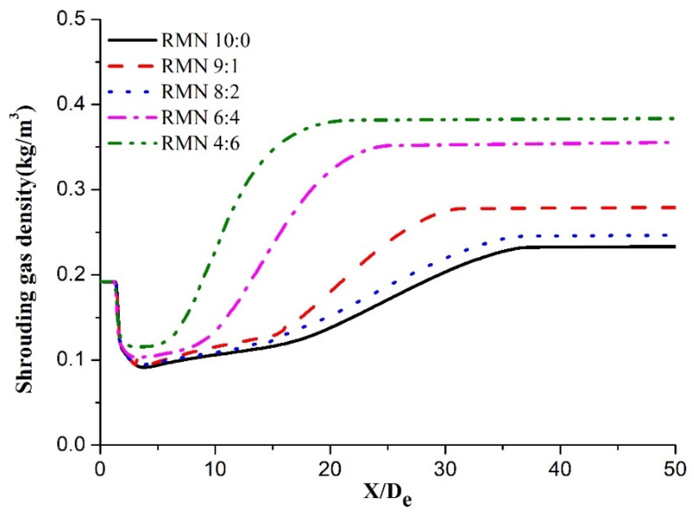
3.2. Density Distribution

The external environment gas density surrounding the main oxygen jet has a strong influence on the velocity distribution of the main oxygen jet. It is necessary to study the density distribution of shrouding gas under different RMN conditions. The density of the shrouding gas is indeed difficult to measure by experimental methods. Therefore, the density distribution is studied by numerical simulation data. Figure 8 is drawn by taking a straight line of Y = De in the flow field and recording the density on the straight line. The abscissa in Figure 8 represents the distance from the nozzle exit plane on the line Y = De, and the ordinate is the density at different positions on the line Y = De. If the shrouding gas does not burn, the density of the shrouding mixture gas is basically unchanged. However, due to the combustion reaction and the formation of new products, the density of shrouding mixture gas is different along the jet direction. It can be seen from Figure 8 that the density of the shrouding gas is increasing with the increase in nitrogen content. Here, the density distribution in the high-temperature flame region is essentially the same across various shrouding gas RMNs. The density first decreases rapidly to its minimum value, then increases continuously, and finally remains essentially constant. This is consistent with the combustion process of the shrouding methane gas. After leaving the nozzle exit, the combustion reaction of the shrouding gas begins rapidly, forming a high-temperature flame region, and the density in the high-temperature region decreases rapidly to its lowest value. Then, as the combustion reaction progresses, the methane concentration in the shrouding gas decreases continuously, causing the combustion temperature to decrease continuously. The density of the high-temperature region gradually rises and finally stabilizes.
As the nitrogen content in the shrouding gas increases, the minimum density in the high-temperature flame region increases from 0.91 kg/m3 at RMN = 10:0 to 1.11 kg/m3 at RMN = 4:6. At the same time, the methane content decreases gradually in the shrouding gas, the density in the high-temperature region grows faster and faster, with the length of the low-density region of the high-temperature flame decreasing from 36 De at RMN = 10:0 to 16 De at RMN = 4:6. With the external environment gas density decreasing, the mixing effect between the main oxygen jet and the external environment gas decreases [30]. The longer the length of the low-density region, the denser the envelope of the high-temperature gas on the main oxygen jet, and the thinner the mixed layer. These findings are consistent with the Mach number distribution trend for the main oxygen jet in Figure 5.

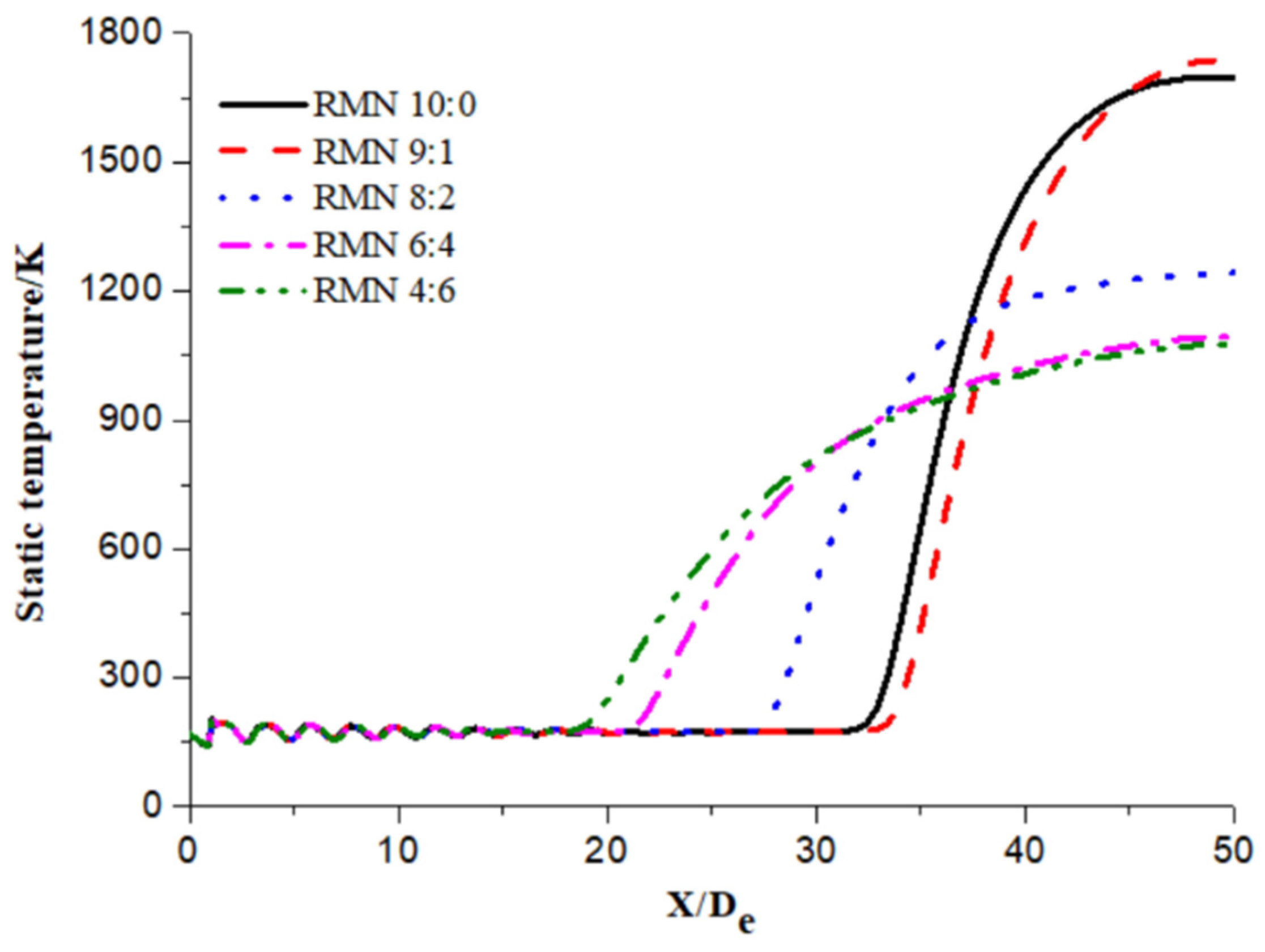
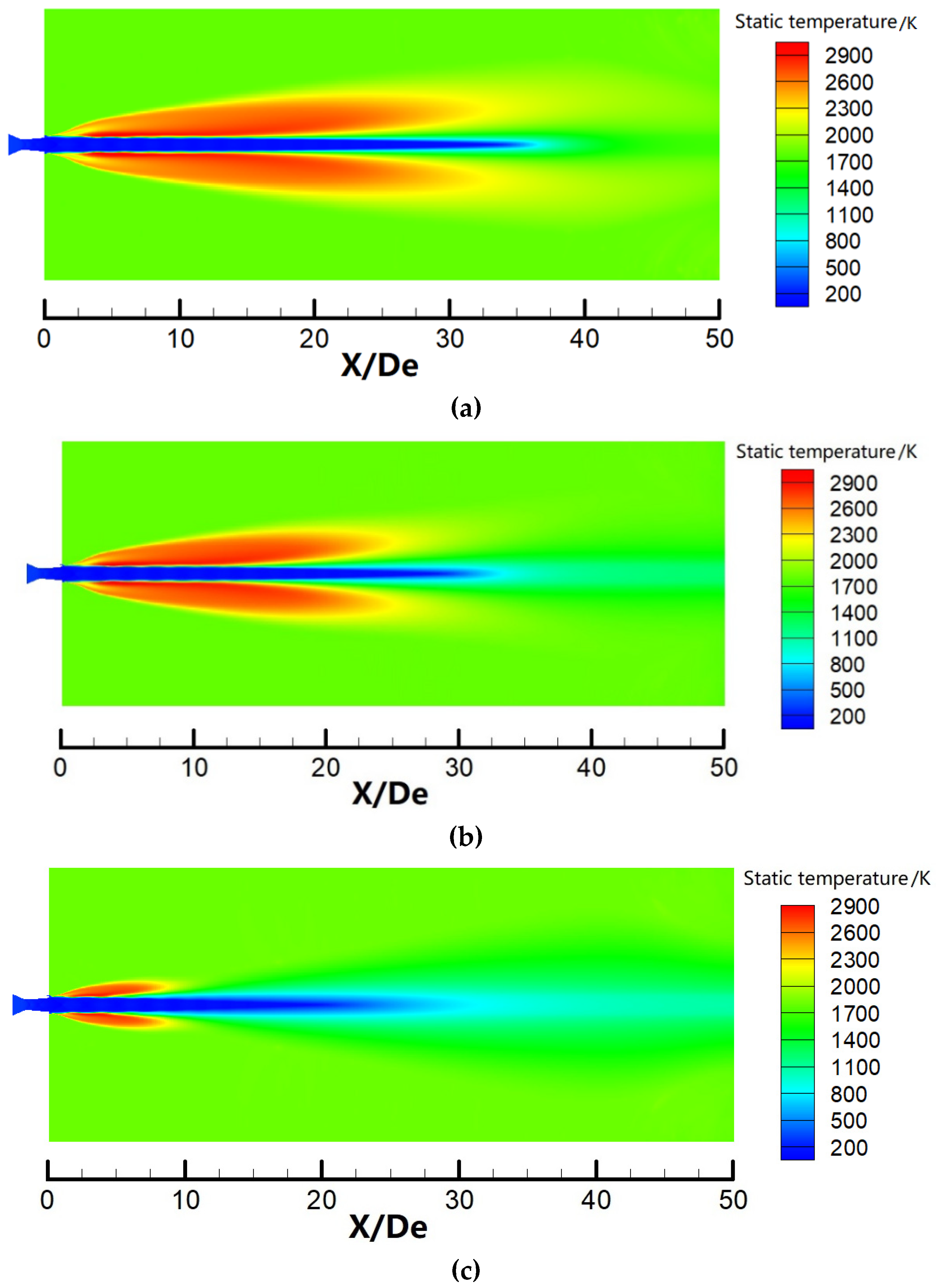
3.3. Temperature Distribution

The purpose of this paper is to study the envelope of the shrouding mixture gas to the main oxygen jet, and to study the ability to inhibit main oxygen jet velocity attenuation and improve the impact ability of the oxygen jet on the molten pool. Therefore, the heat transfer from the shrouding gas to the arc furnace slag is unconcerned in this paper. The main oxygen jet’s axial static temperature distribution is shown for various jets in Figure 9. The static temperature distribution for various jets shown in Figure 9 is the result of numerical simulation. Under various shrouding gas RMN conditions, the static temperature of the main oxygen jet fluctuates after leaving the nozzle exit, and then the main oxygen jet temperature remains constant, at last, the main oxygen jet temperature continues to rise, ultimately tending to the external ambient temperature. These findings are consistent with the main oxygen jet’s Mach number distribution trend. This consistency is due to the fact that the total energy of the main oxygen jet includes both internal energy and kinetic energy, the former of which can be characterized by the static temperature and the latter of which can be characterized by the Mach number of the main oxygen jet. The temperature core length is the longest distance from the nozzle exit when the temperature remains substantially constant. It is similar to the concept of velocity core length. The temperature core length reflects the degree that the main oxygen jet is not affected by the external environment. The longer the temperature core length, the better the envelope of the shrouding gas on the main oxygen jet. Based on the principle of energy conservation, the static temperature and the Mach number of the oxygen jet should simultaneously fluctuate in opposite directions. As the nitrogen content in the shrouding gas increases, the temperature core length decreases. Under the condition that the shrouding gas is pure methane, the temperature core length reaches 32 De. At a nitrogen content of 60%, the temperature core length is only 19 De. These findings show that as the nitrogen content increases continuously, the length of the high-temperature region generated by shrouding gas combustion decreases, the envelope of the high-temperature shrouding gas on the main oxygen jet gradually thins, and the material exchange between the main oxygen jet and the external environment gas is gradually enhanced, resulting in a decrease in the length of the oxygen jet’s high-temperature core. The length of the oxygen jet’s high-temperature core remains basically unchanged between shrouding gas RMN conditions of 10:0 and 9:1. As the nitrogen content continues to increase, the main oxygen jet’s high-temperature core length decreases continuously. This decrease first accelerates and then decelerates. This finding shows again that while a small amount of nitrogen in the shrouding gas has little effect on its combustion, an increase in nitrogen content causes the length of the shrouding gas combustion region to decrease rapidly.
Figure 10 is the static temperature contours of the supersonic combustion coherent jet under different conditions calculated. In the figure, the main oxygen jet is enveloped by the high-temperature flame of the shrouding gas. The longer the high-temperature region, the longer the oxygen jet’s high-temperature core length. The high-temperature flame region effectively reduces the exchange of material and energy between the main oxygen jet and the external atmospheric environment, allowing the temperature of the main oxygen jet to remain stable within a certain length range. However, as the nitrogen content in the shrouding gas increases, the length of the high-temperature flame region shortens considerably. A shrouding gas of pure methane produces a high-temperature flame region length of about 32 De, but a shrouding gas with a nitrogen content of 60% produces a high-temperature flame region of only 10 De in length. After that, the main oxygen jet exchanges heat directly with the external atmospheric environment. Here the atmospheric environmental temperature is about 1700 K, which is far lower than the shrouding gas combustion temperature. Therefore, as the nitrogen content increases, the equilibrium temperature of the main oxygen jet continues to decrease once it has developed. This effect also explains why the static temperature of the main oxygen jet at X = 50 De is at its minimum when the RMN of the shrouding gas is 6:4 or 4:6, as shown in Figure 9.

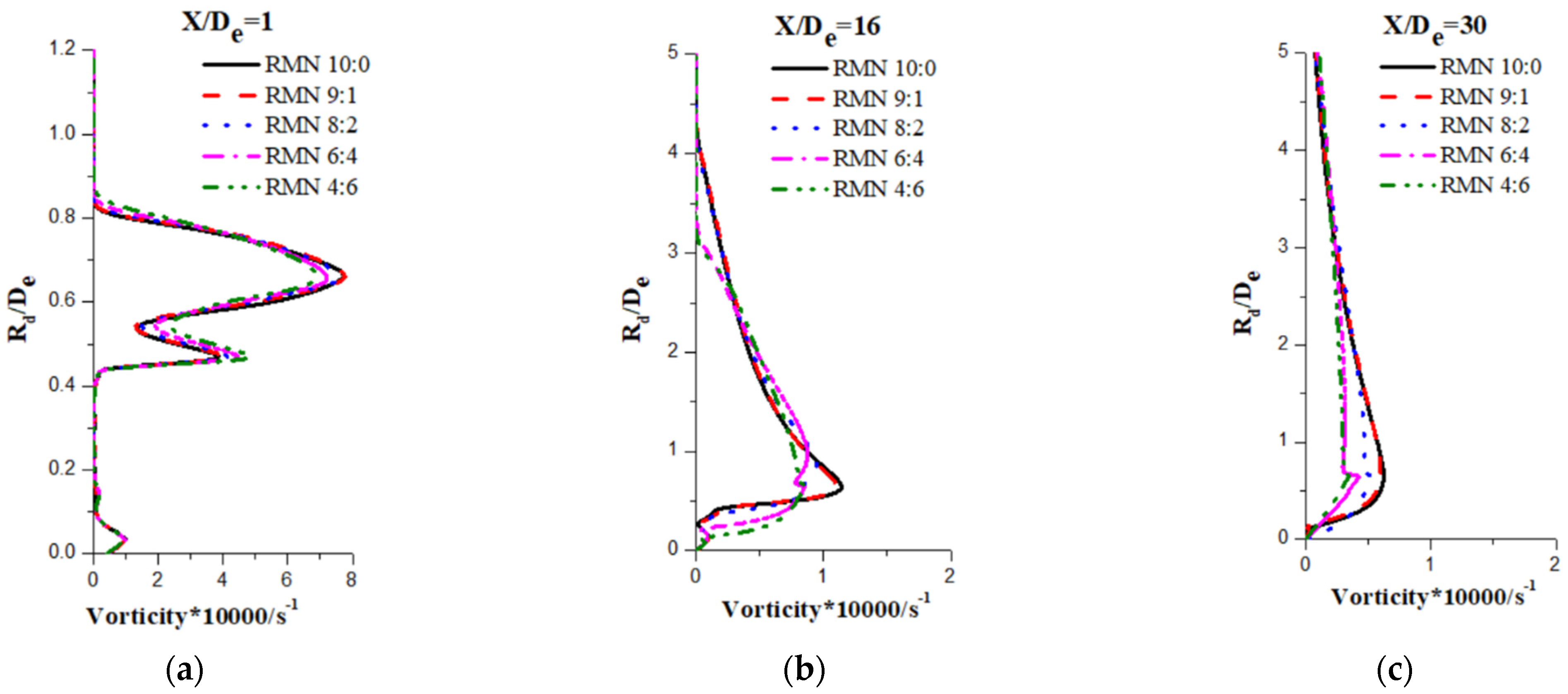
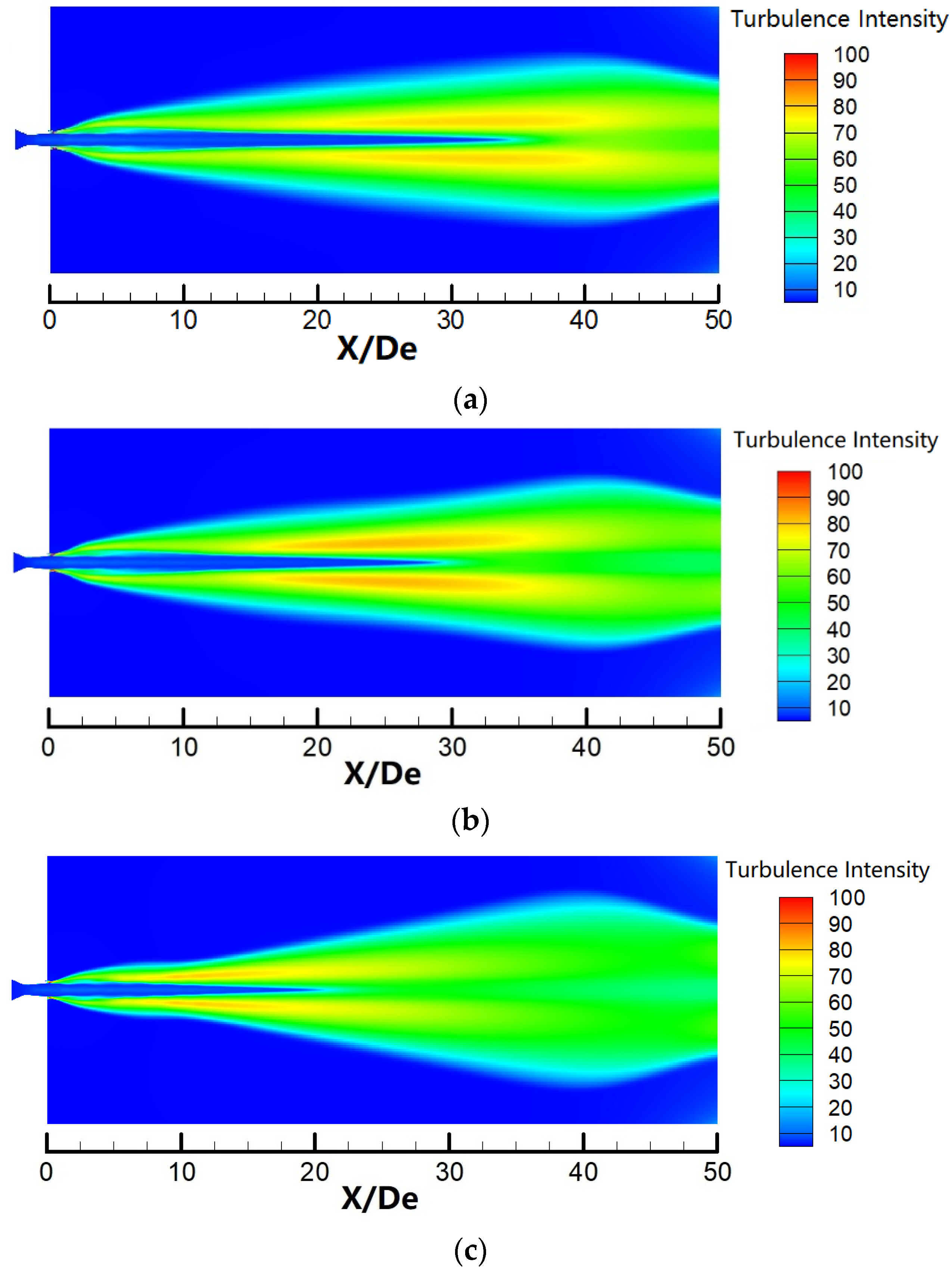
3.4. Vorticity and Turbulence Intensity

In order to study the interaction between the main oxygen jet and the surrounding gas, the vorticity magnitude distributions of the main oxygen jet at different distances from the nozzle exit (X/De = 1, 16, and 30) along the jet direction under different RMN conditions were analyzed and are shown in Figure 11. The y-axis is the ratio between the radial distance Rd and the main oxygen nozzle exit diameter, while the x-axis is the vorticity magnitude. The larger the vorticity magnitude, the greater the mixing degree between the oxygen jet and the surrounding gas. Figure 11a shows that the vorticity magnitude distribution trend is essentially the same under various RMN conditions at X = 1 De because the shrouding gases for various nitrogen content values at this position are all in a combustion state and have the same protective effect on the main oxygen jet. The peak at Rd = 0.5 De is caused by the interaction between the main oxygen jet and the high-temperature gas generated by shrouding gas combustion, while the peak at Rd = 0.7 De is caused by the interaction between the high-temperature shrouding gas and the gas in the external static environment. The velocity difference between the high-temperature shrouding gas and gas in the external environment is significantly higher than that between the high-temperature shrouding gas and the main oxygen jet, so the second peak has a much higher intensity than the first peak.
As the oxygen jet moves forward, the interactions of the high-temperature shrouding gas with the main oxygen jet and with the external static environment gas weaken. Therefore, for X = 16 De, as shown in Figure 11b, the vorticity magnitude distribution has only one peak. There is still a strong interaction between the high-temperature shrouding gas and the external static environment gas, but its peak value is significantly lower than the peak value at the same position in Figure 11a, and the interaction between the high-temperature shrouding gas and the main oxygen jet cannot be clearly observed. In addition, Figure 11b shows that the vorticity magnitude distribution is essentially the same for RMN conditions of 9:1 and 10:0. This constancy indicates that a small amount of nitrogen does not significantly alter the shrouding gas combustion effect. With increasing nitrogen content in the shrouding gas, the vorticity magnitude continues to decrease. That is, the interaction between the shrouding gas and the gas in the external environment is weakened, the combustion effect of the shrouding gas weakens, and the envelope of the shrouding gas around the main oxygen jet thus also weakens. The vorticity magnitude shown in Figure 10c again illustrates the same phenomenon.
Figure 12 shows the turbulence intensity contours for various jets. The turbulence intensity of the main oxygen jet is relatively small due to the envelope of the high-temperature flame, while the turbulence intensity of the high-temperature flame region is large due to the combustion effect and the interaction with the gas in the external environment. It can be seen from the numerical simulation results that the longer the length of the shrouding gas combustion area, the better the envelope of the flame on the main oxygen jet. The stronger the interaction between the shrouding gas replacing the main oxygen jet and the external environment gas, the greater the turbulence intensity. Therefore, the coherent jet temperature distribution is consistent with the turbulence distribution. As the nitrogen content of the shrouding gas increases, the length of the main oxygen jet’s low-turbulence region decreases continuously, as does the length of the high-turbulence region of the high-temperature shrouding gas. The length of the main oxygen jet’s low-turbulence region decreases from 34 De at RMN = 10:0 (Figure 12a) to 20 De at RMN = 4:6 (Figure 12c). Due to the envelope of high-temperature shrouding gas around the main oxygen jet, the high-temperature shrouding gas replaces the main oxygen jet to interact with the gas in the external static environment, so the main oxygen jet maintains a state of low turbulence. However, with increasing nitrogen content in the shrouding gas, the combustion effect of the shrouding gas is affected, resulting in decreases in the lengths of the shrouding gas combustion and high-turbulence-intensity regions, thus weakening the envelope around the main oxygen jet. This trend results in increased interaction between the main oxygen jet and the gas in the external environment, and the length of the main oxygen jet’s low-turbulence area decreases. This finding is consistent with the distribution trend in static temperature contours for coherent jets, as seen in Figure 9.

4. Conclusions

Numerical simulations and experimental methods were used to study and analyze the characteristics of a supersonic combustion coherent jet under various shrouding gas ratios of methane to nitrogen. The results of the numerical simulation and experiment have a good agreement, and some conclusions were obtained.
The mixing of nitrogen into supersonic shrouding methane gas influences the characteristics of the supersonic combustion coherent jet. As the proportion of nitrogen increases, the high-temperature flame region of the supersonic shrouding gas becomes shorter in length, and the high-temperature flame density increases. These effects lead to a weakening of the envelope around the main oxygen jet, decreases in the velocity and high-temperature core length of the main oxygen jet, and a decrease in the length of the low-turbulence region. However, the effect of nitrogen content on the main oxygen jet characteristics is not linear. When the nitrogen component is increased slightly (from 0% to about 10%), the Mach number, temperature, half-velocity width, and turbulence intensity distribution of the main oxygen jet remain essentially unchanged, and the high-velocity core length is reduced by only 3%. However, further increases in nitrogen content impact the characteristics of the main oxygen jet, first more strongly and then more weakly. Therefore, it is feasible to reduce the smelting cost by including a nitrogen component of about 10%, given that the impact ability of the supersonic combustion coherent jet remains basically unchanged.
In this paper, the numerical simulation results are verified only by measuring the main oxygen jet pressure to calculate the local Mach number, and the jet temperature is not measured. This is mainly because contact methods such as thermocouples are not suitable for the measurement of coherent jet temperature in high temperature environment. The research team is planning to use non-contact measurements such as TDLAS (Tunable Diode Laser Absorption Spectroscopy) to measure the temperature and composition of the coherent jet.
The results of this study provide data support for the research and development of supersonic combustion coherent jet technology, and prove the feasibility of reducing the smelting cost by shrouding supersonic methane and nitrogen mixture gas. However, these studies are still not comprehensive, and it is necessary to study the structural design of the supersonic combustion coherent jet nozzle, such as the influence of the combustion chamber on the combustion of the shrouding fuel gas. Such work will substantially deepen the state of knowledge regarding the influence of key parameters on supersonic combustion coherent jet characteristics.

Author Contributions

Conceptualization, R.Z.; Investigation, F.Z. and T.D.; Methodology, W.W.; Data Curation, W.W. and F.Z.; Writing—Original Draft Preparation, F.Z. and T.D.; Writing—Review and Editing, F.Z., R.Z. and W.W. All authors have read and agreed to the published version of the manuscript.

Funding

This research was funded by the Fundamental Research Funds for the Central Universities (Grant number FRF-MP-20-46).

Institutional Review Board Statement

Not applicable.

Informed Consent Statement

Not applicable.

Data Availability Statement

Not applicable.

Conflicts of Interest

The authors declare no conflict of interest.

References

  1. Yang, L.Z.; Hu, H.; Yang, Z.S. A review on bath fluid flow stirring technologies in EAF steelmaking. J. Iron Steel Res. Int. 2021, 28, 1341–1351. [Google Scholar] [CrossRef]
  2. Echterhof, T. Review on the use of alternative carbon sources in EAF steelmaking. Metals 2021, 11, 222. [Google Scholar] [CrossRef]
  3. Eshwar, K.R.; Ville, V.V.; Petri, S. Numerical modelling of the influence of argon flow rate and slag layer height on open-eye formation in a 150ton steelmaking ladle. Metals 2019, 9, 1048. [Google Scholar] [CrossRef] [Green Version]
  4. Zhang, B.; Chen, K.; Wang, R.F. Physical modelling of splashing triggered by the gas jet of an oxygen lance in a converter. Metals 2019, 9, 409. [Google Scholar] [CrossRef] [Green Version]
  5. Odenthal, H.J.; Kemminger, A.; Krause, F. Review on modeling and simulation of the electric arc furnace. Steel Res. Int. 2017, 89, 1700098. [Google Scholar] [CrossRef]
  6. Ersson, M.; Tilliander, A.; Jonsson, L. A mathematical model of an impinging air jet on a water surface. ISIJ Int. 2008, 48, 377–384. [Google Scholar] [CrossRef] [Green Version]
  7. Sabah, S.; Brooks, G. Splash distribution in oxygen steelmaking. Metall. Mater. Trans. B 2015, 46, 863–872. [Google Scholar] [CrossRef]
  8. Malfa, E.; Giavani, C.; Memoli, F. Numerical simulation of a supersonic oxygen lance for industrial application in EAFs. MPT Int. 2005, 28, 44–50. [Google Scholar]
  9. Zhao, F.; Sun, D.; Zhu, R. Effect of shrouding gas parameters on characteristics of supersonic coherent jet. Metall. Mater. Trans. B 2017, 48, 1807–1816. [Google Scholar] [CrossRef]
  10. Meidani, A.R.N.; Isac, M.; Richardson, A. Modelling shrouded supersonic jets in metallurgical reactor vessels. ISIJ Int. 2004, 44, 1639–1645. [Google Scholar] [CrossRef] [Green Version]
  11. Sumi, I.; Kishimoto, Y.; Kikuchi, Y. Effect of high-temperature field on supersonic oxygen jet behavior. ISIJ Int. 2006, 46, 1312–1317. [Google Scholar] [CrossRef]
  12. Sumi, I.; Okuyama, G.; Nabeshima, S. Behavior of top-blown jet under reduced pressure. ISIJ Int. 2007, 47, 73–79. [Google Scholar] [CrossRef] [Green Version]
  13. Klioutchnikov, I.; Olivier, H.; Odenthal, J. Numerical investigation of coaxial jets entering into a hot environment. Comp. Fluids 2013, 86, 490–499. [Google Scholar] [CrossRef]
  14. Wei, G.S.; Zhu, R.; Yang, L.Z. Modeling on impact zone volume generated by coherent supersonic jet and conventional supersonic jet. J. Iron Steel Res. Int. 2018, 25, 681–691. [Google Scholar] [CrossRef]
  15. Alam, M.; Naser, J.; Brooks, G. Computational fluid dynamics modeling of supersonic coherent jets for electric arc furnace steelmaking process. Metall. Mater. Trans. B 2010, 47, 1354–1367. [Google Scholar] [CrossRef]
  16. Alam, M.; Naser, J.; Brooks, G. Computational fluid dynamics simulation of supersonic oxygen jet behavior at steelmaking temperature. Metall. Mater. Trans. B 2010, 41, 636–645. [Google Scholar] [CrossRef]
  17. Alam, M.; Naser, J.; Brooks, G. A computational fluid dynamics model of shrouded supersonic jet impingement on a water surface. ISIJ Int. 2018, 52, 1026–1035. [Google Scholar] [CrossRef] [Green Version]
  18. Li, X.; Wei, G.S.; Zhu, R.; Tian, B.H.; Zhao, R.M.; Lan, X.Y. Study on the Characteristics of Coherent Supersonic Jet with Superheated Steam. Metals 2022, 12, 835. [Google Scholar] [CrossRef]
  19. Tang, G.W.; Chen, Y.; Silaen, A.K. Effects of fuel input on coherent jet length at various ambient temperatures. App. Ther. Eng. 2019, 153, 513–523. [Google Scholar] [CrossRef]
  20. Tang, G.W.; Chen, Y.; Silaen, A.K. Investigation on coherent jet potential core length in an electric arc furnace. Steel Res. Int. 2018, 90, 1504–1516. [Google Scholar] [CrossRef]
  21. Cheng, T.; Zhu, R.; Dong, K. Effect of methane-hydrogen mixtures on flow and combustion of coherent jets. J Iron Steel Res. Int. 2017, 24, 1143–1151. [Google Scholar] [CrossRef]
  22. Zhao, F.; Zhu, R.; Wang, W.R. Characteristics of a Coherent Jet Enshrouded in a Supersonic Fuel Gas. Int. J. Min. Met. Mater. 2020, 27, 173–180. [Google Scholar] [CrossRef]
  23. Zhao, F.; Zhu, R.; Wang, W.R. Characteristics of the Supersonic Combustion Coherent Jet for Electric Arc Furnace Steelmaking. Materials 2019, 12, 3504. [Google Scholar] [CrossRef] [PubMed] [Green Version]
  24. Anderson, J.D. Introduction to Flight; McGraw-Hill Education: Singapore, Singapore, 2013; pp. 125–131. [Google Scholar]
  25. Versteeg, H.K.; Malalasekera, W. An Introduction to Computational Fluid Dynamics, the Finite Volume Method; Prentice Hall: London, UK, 2007; pp. 157–179. [Google Scholar]
  26. Abdolhamid, K.S.; Pao, S.P.; Massey, S.J. Temperature corrected turbulence model for high temperature jet flow. J. Fluids Eng. 2006, 126, 844–850. [Google Scholar] [CrossRef]
  27. Menter, F.R. Two-equation eddy-viscosity turbulence models for engineering applications. AIAA J. 1994, 32, 1598–1605. [Google Scholar] [CrossRef] [Green Version]
  28. Zhao, F.; Zhu, R.; Zhang, Y.L.; Wang, H. Turbulence model in supersonic jet flow field. Chin. J. Eng. 2014, 36, 366–372. [Google Scholar] [CrossRef]
  29. Jones, W.P.; Whitelaw, J.H. Calculation methods for reacting turbulent flows: A review. Combust. Flame. 1982, 48, 1–26. [Google Scholar] [CrossRef]
  30. Papamoschou, D.; Roshko, A. The compressible turbulent shear layer: An experimental study. J. Fluid Mech. 1988, 197, 453–477. [Google Scholar] [CrossRef]
Figure 1. Structure diagram of the supersonic combustion coherent jet nozzle.
Metals 13 00123 g001
Figure 2. Schematic of the experimental apparatus.
Metals 13 00123 g002
Figure 3. Calculation model and boundary conditions.
Metals 13 00123 g003
Figure 4. Axial Mach number distribution for various grid densities.
Metals 13 00123 g004
Figure 5. Axial Mach number distribution for various jets.
Metals 13 00123 g005
Figure 6. Velocity core length for various jets.
Metals 13 00123 g006
Figure 7. Half-jet width distribution for various jets.
Metals 13 00123 g007
Figure 8. Shrouding gas density at y = De for various jets.
Metals 13 00123 g008
Figure 9. Static temperature distribution for various jets.
Metals 13 00123 g009
Figure 10. Static temperature contours for three jets: (a) methane: nitrogen ratio (RMN) = 10:0; (b) RMN = 8:2; and (c) RMN = 4:6.
Metals 13 00123 g010
Figure 11. Vorticity magnitude radial distributions at various axial locations for three jets: (a) methane: nitrogen ratio (RMN) = 10:0, (b) RMN = 8:2, and (c) RMN = 4:6.
Metals 13 00123 g011
Figure 12. Turbulence intensity contours for three jets: (a) methane: nitrogen ratio (RMN) = 10:0, (b) RMN = 8:2, and (c) RMN = 4:6.
Metals 13 00123 g012
Table 1. Parameters of boundary condition.
Name of BoundaryType of Boundary ConditionValues
Supersonic main oxygen inletMach number2
mass flow rate0.8 kg·s−1
mass fractionsO2 = 100%
total temperature300 K
Supersonic shrouding gas inletMach number2
mass flow rate0.04 kg·s−1
mass fractionsCH4:N2 =10:0/9:1/8:2/6:4
temperature300 K
Pressure inletstatic pressure101,325 Pa
mass fractionsO2 = 21%, N2 = 79%
temperature1700 K
Pressure outletstatic pressure101,325 Pa
mass fractionsO2 = 21%, N2 = 79%
temperature1700 K
Wallno-slip300 K/1700 K
Disclaimer/Publisher’s Note: The statements, opinions and data contained in all publications are solely those of the individual author(s) and contributor(s) and not of MDPI and/or the editor(s). MDPI and/or the editor(s) disclaim responsibility for any injury to people or property resulting from any ideas, methods, instructions or products referred to in the content.

