
Suitability of Eroded Particles from Die-Sink Electro Discharge Machining for Additive Manufacturing—Review, Characterization and Processing


Abstract
:
1. Introduction
2. EDM Eroded Particles
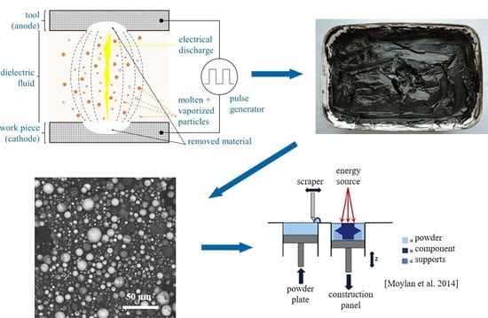
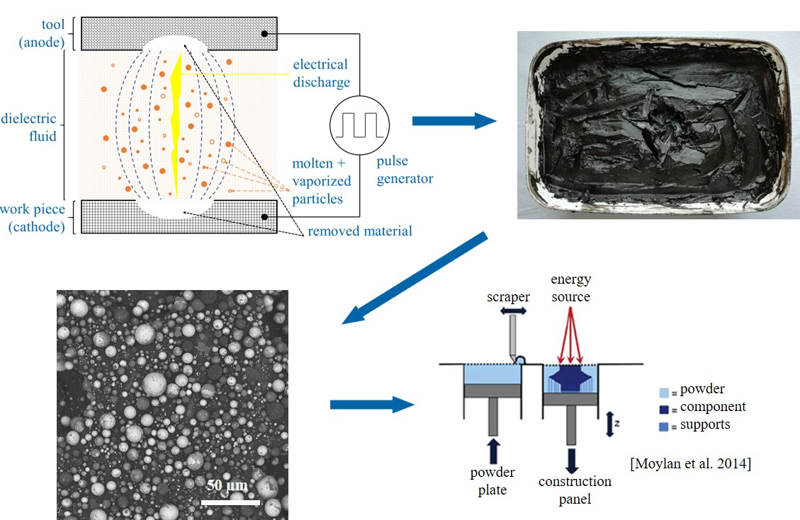
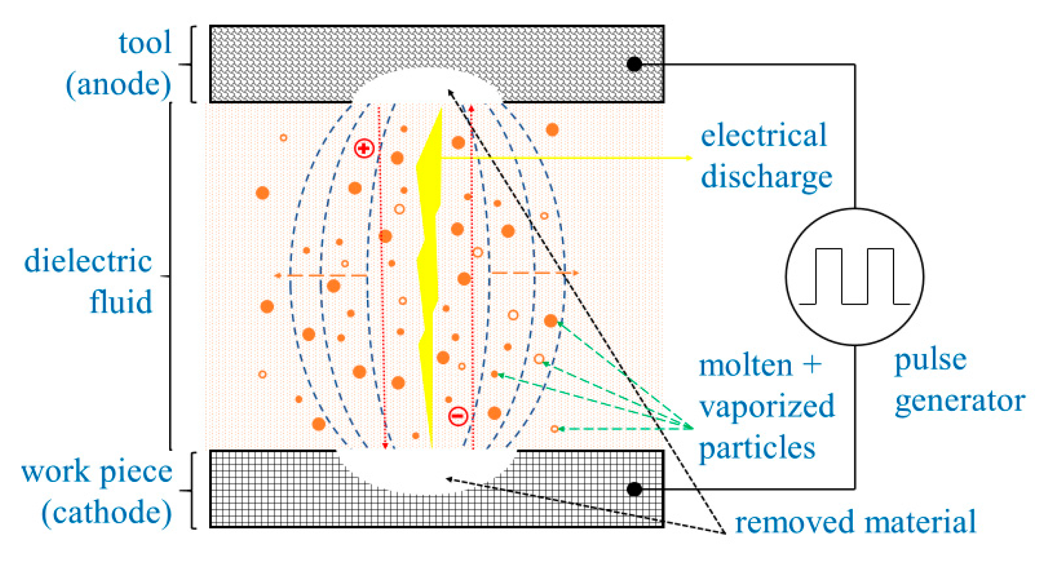
2.1. Particle-Generation Mechanisms
2.2. Influence of Machining Settings
3. Comprehensive Overview of Selected Literature
4. Materials and Methods
5. Results and Discussion
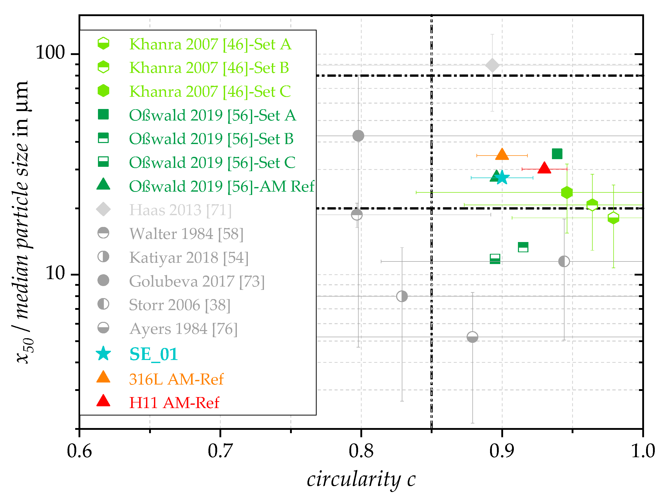
5.1. Comparison of Literarue Values, Real Waste Streams and AM Reference Materials
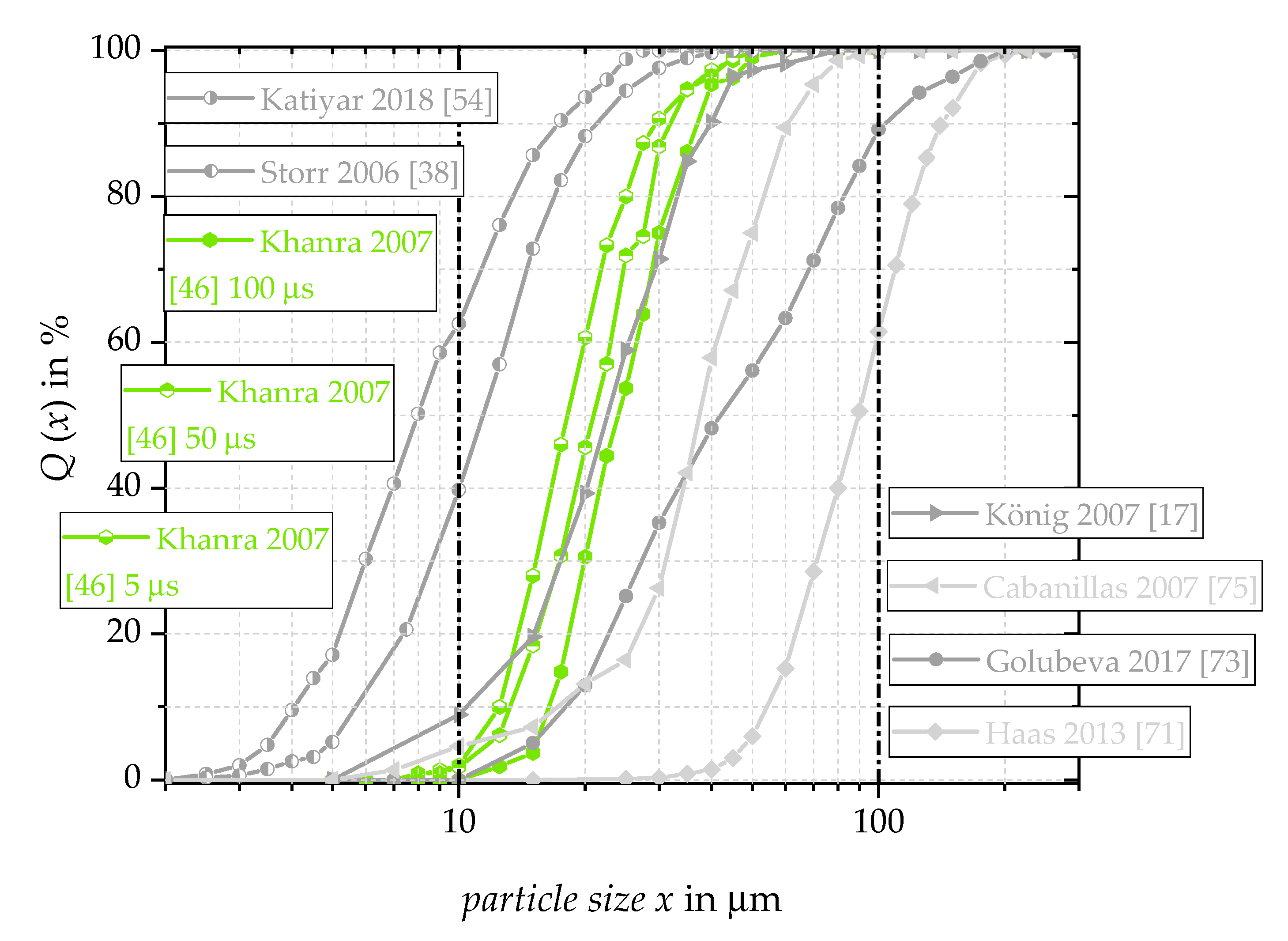
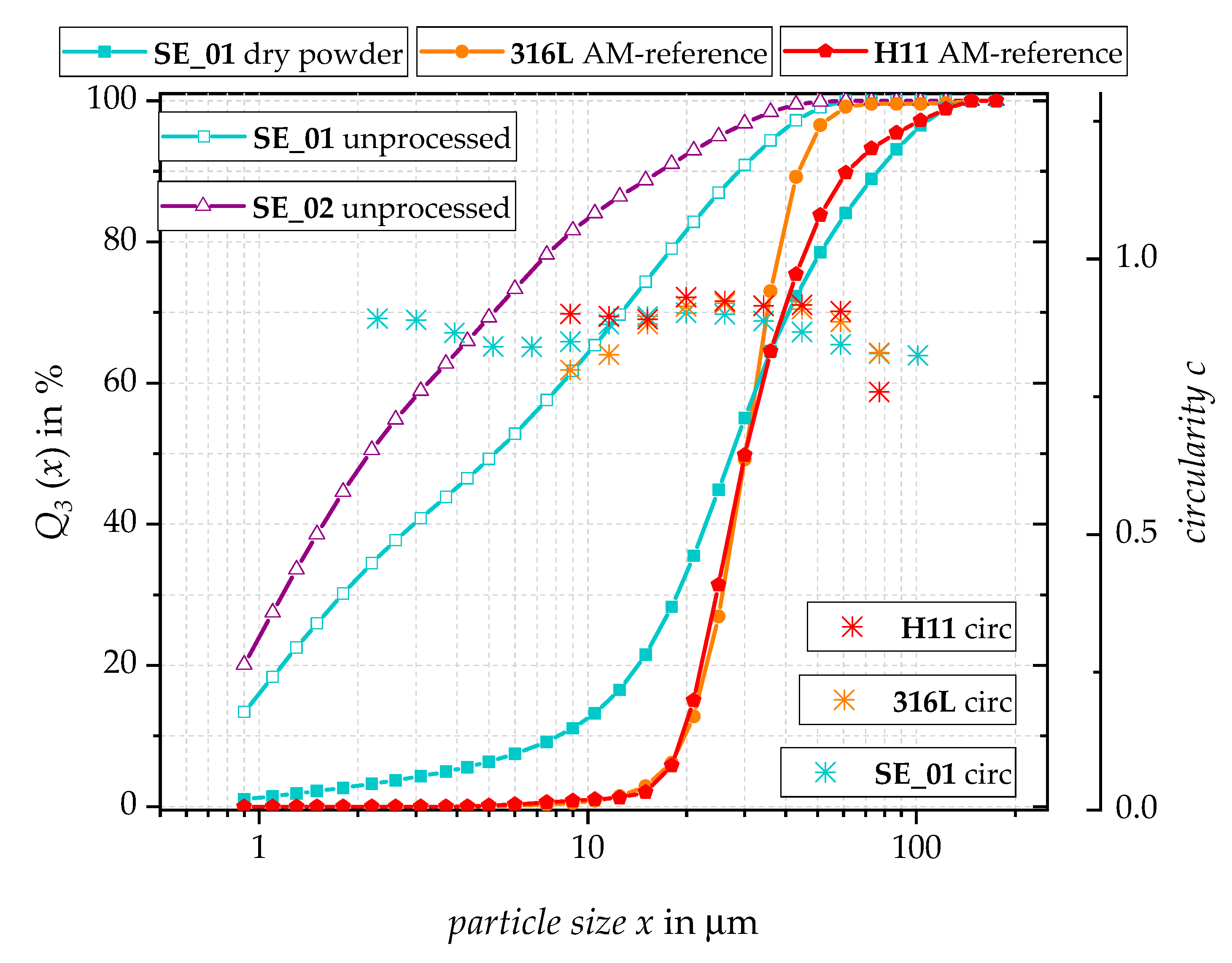
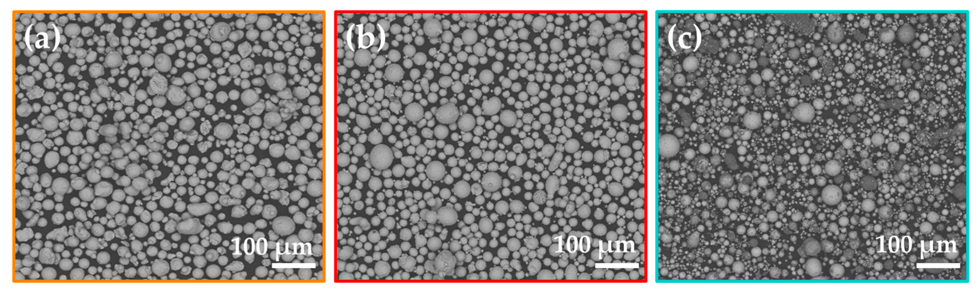
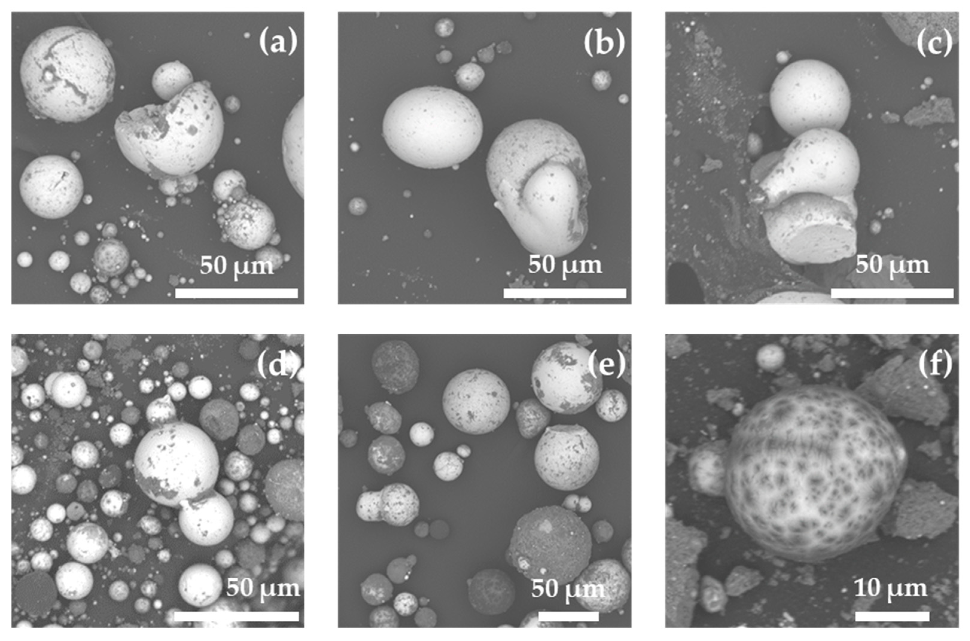
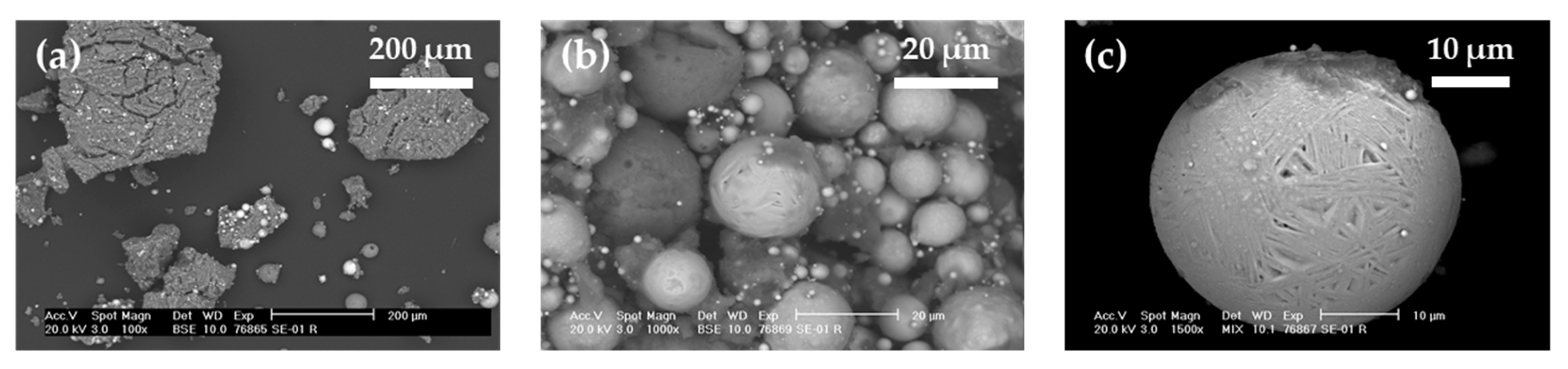
5.2. Particle Size Distributions and Particle Morphologies
5.3. Chemical Composition
6. Conclusions and Outlook
Author Contributions
Funding
Data Availability Statement
Acknowledgments
Conflicts of Interest
References
- Petrofes, N.F.; Gadalla, A.M. Electrical discharge machining of advanced ceramics. Am. Ceram. Soc. Bull. 1988, 67, 1048–1052. [Google Scholar]
- Ho, K.H.; Newman, S.T. State of the art electrical discharge machining (EDM). Int. J. Mach. Tools Manuf. 2003, 43, 1287–1300. [Google Scholar] [CrossRef]
- Guu, Y.H.; Hocheng, H.; Chou, C.Y.; Deng, C.S. Effect of electrical discharge machining on surface characteristics and machining damage of AISI D2 tool steel. Mater. Sci. Eng. A 2003, 358, 37–43. [Google Scholar] [CrossRef]
- Schumacher, B.M. After 60 years of EDM the discharge process remains still disputed. J. Mater. Processing Technol. 2004, 149, 376–381. [Google Scholar] [CrossRef]
- Mohd Abbas, N.; Solomon, D.G.; Fuad Bahari, M. A review on current research trends in electrical discharge machining (EDM). Int. J. Mach. Tools Manuf. 2007, 47, 1214–1228. [Google Scholar] [CrossRef]
- Ayers, J.D. Initiation of ZrC Dendritic Growth on the Surface of Spark Machined Zirconium. Metall. Trans. A 1983, 14, 5–10. [Google Scholar] [CrossRef]
- Sato, T.; Usuki, K.; Okuwaki, A.; Goto, Y. Synthesis of metal nitrides and carbide powders by a spark discharge method in liquid media. J. Mater. Sci. 1992, 27, 3879–3882. [Google Scholar] [CrossRef]
- Kocova, M.; Pizurova, N.; Süllow, S.; Schneeweiss, O. Composition and tempering of Fe-C and Fe-Ni-C fine particles prepared by spark erosion. Mater. Sci. Eng. A 1995, 190, 259–265. [Google Scholar] [CrossRef]
- Cabanillas, E.D.; López, M.; Pasqualini, E.E.; Cirilo Lombardo, D.J. Production of uranium–molybdenum particles by spark-erosion. J. Nucl. Mater. 2004, 324, 1–5. [Google Scholar] [CrossRef]
- Schumacher, B.M.; Krampitz, R.; Kruth, J.P. Historical Phases of EDM Development Driven by the Dual Influence of “Market Pull” and “Science Push”. Procedia CIRP 2013, 6, 5–12. [Google Scholar] [CrossRef]
- Lazarenko, B.R. About the Inversion of Metal Erosion and Methods to Fight Ravage of Electric Contacts; WEI-Ins: Moscou, Russia, 1943. [Google Scholar]
- Lazarenko, B.R.; Lazarenko, N.I. Physics of the Spark Method of Machining Metals; TsBTI MÉP: Moscow, Russia, 1946. [Google Scholar]
- Solotych, B.N. Fundamental Physics of Electroerosion on Metals; Physics-Mathematical Library (Gostekhisdat): Moscou, Russia, 1953. [Google Scholar]
- Zolotykh, B. The mechanism of electrical erosion of metals in liquid dielectric media. Soviet Phys. Tech. Phys. 1959, 4, 1370. [Google Scholar]
- Bucklow, I.; Cole, M. Spark-machining. Metall. Rev. 1969, 14, 103–118. [Google Scholar] [CrossRef]
- Lunina, M.A.; Novozhil, Y.A. Electrical condensation method for preparation of metal dispersions in organic media. Colloid J. Ussr 1969, 31, 370. [Google Scholar]
- König, W.; Klocke, F. Fertigungsverfahren: Abtragen, Gnerieren und Lasermaterialbearbeitung; Springer: Berlin/Heidelberg, Germany, 2007; Volume 4, p. 412. [Google Scholar]
- Li, L.; Li, Z.Y.; Wei, X.T.; Cheng, X. Machining Characteristics of Inconel 718 by Sinking-EDM and Wire-EDM. Mater. Manuf. Processes 2014, 30, 968–973. [Google Scholar] [CrossRef]
- Yilmaz, O.; Okka, M.A. Effect of single and multi-channel electrodes application on EDM fast hole drilling performance. Int. J. Adv. Manuf. Technol. 2010, 51, 185–194. [Google Scholar] [CrossRef]
- Schubert, A.; Zeidler, H.; Hahn, M.; Hackert-Oschätzchen, M.; Schneider, J. Micro-EDM Milling of Electrically Nonconducting Zirconia Ceramics. Procedia CIRP 2013, 6, 297–302. [Google Scholar] [CrossRef]
- Gholipoor, A.; Baseri, H.; Shabgard, M.R. Investigation of near dry EDM compared with wet and dry EDM processes. J. Mech. Sci. Technol. 2015, 29, 2213–2218. [Google Scholar] [CrossRef]
- Singh Bains, P.; Sidhu, S.S.; Payal, H.S. Investigation of magnetic field-assisted EDM of composites. Mater. Manuf. Processes 2017, 33, 670–675. [Google Scholar] [CrossRef]
- Nani, V.-M. The ultrasound effect on technological parameters for increase in performances of W-EDM machines. Int. J. Adv. Manuf. Technol. 2016, 88, 519–528. [Google Scholar] [CrossRef]
- DebRoy, T.; Wei, H.L.; Zuback, J.S.; Mukherjee, T.; Elmer, J.W.; Milewski, J.O.; Beese, A.M.; Wilson-Heid, A.; De, A.; Zhang, W. Additive manufacturing of metallic components—Process, structure and properties. Prog. Mater. Sci. 2018, 92, 112–224. [Google Scholar] [CrossRef]
- Ngo, T.D.; Kashani, A.; Imbalzano, G.; Nguyen, K.T.Q.; Hui, D. Additive manufacturing (3D printing): A review of materials, methods, applications and challenges. Compos. Part B Eng. 2018, 143, 172–196. [Google Scholar] [CrossRef]
- Gu, D.D.; Meiners, W.; Wissenbach, K.; Poprawe, R. Laser additive manufacturing of metallic components: Materials, processes and mechanisms. Int. Mater. Rev. 2013, 57, 133–164. [Google Scholar] [CrossRef]
- Bourell, D.; Kruth, J.P.; Leu, M.; Levy, G.; Rosen, D.; Beese, A.M.; Clare, A. Materials for additive manufacturing. CIRP Ann. 2017, 66, 659–681. [Google Scholar] [CrossRef]
- Singh, S.; Ramakrishna, S.; Singh, R. Material issues in additive manufacturing: A review. J. Manuf. Processes 2017, 25, 185–200. [Google Scholar] [CrossRef]
- Strondl, A.; Lyckfeldt, O.; Brodin, H.; Ackelid, U. Characterization and Control of Powder Properties for Additive Manufacturing. Jom 2015, 67, 549–554. [Google Scholar] [CrossRef]
- Kruth, J.P.; Froyen, L.; Van Vaerenbergh, J.; Mercelis, P.; Rombouts, M.; Lauwers, B. Selective laser melting of iron-based powder. J. Mater. Process. Technol. 2004, 149, 616–622. [Google Scholar] [CrossRef]
- Liu, B.; Wildman, R.; Tuck, C.; Ashcroft, I.; Hague, R. Investigation The Effect of Particle Size Distribution on Processing Parameters Optimisation In Selective Laser Melting Process. In Proceedings of the 22nd Annual International Solid Freeform Fabrication Symposium—An Additive Manufacturing Conference, Online, 2–4 August 2021; pp. 227–238. [Google Scholar]
- Brandl, E.; Leyens, C.; Palm, F. Mechanical Properties of Additive Manufactured Ti-6Al-4V Using Wire and Powder Based Processes. In Proceedings of the IOP Conference Series Materials Science and Engineering; IOP Publishing: Bristol, UK, 2011; Volume 26. [Google Scholar] [CrossRef]
- Munsch, M.; Schmidt-Lehr, M.; Wycisk, E. Metal Additive Manufacturing with sinter-based technologies. In AM Power Insights; AMPOWER: Hamburg, Germany, 2018. [Google Scholar]
- Statistisches Bundesamt, Kleine und Mittlere Unternehmen. 2020. Available online: https://www.destatis.de/DE/Themen/Branchen-Unternehmen/Unternehmen/Kleine-Unternehmen-Mittlere-Unternehmen/_inhalt.html (accessed on 12 July 2021).
- Tsunekawa, Y.; Ueno, T.; Okumiya, M.; Yashiro, T. Plasma Sprayed Coatings with Water and Gas Atomised Bearing Steel Powders. Surf. Eng. 2013, 19, 17–22. [Google Scholar] [CrossRef]
- Yeo, S.H.; Tan, H.C.; New, A.K. Assessment of waste streams in electric-discharge machining for environmental impact analysis. Proc. Inst. Mech. Eng. Part B 1998, 212, 393–401. [Google Scholar] [CrossRef]
- Leão, F.N.; Pashby, I.R. A review on the use of environmentally-friendly dielectric fluids in electrical discharge machining. J. Mater. Processing Technol. 2004, 149, 341–346. [Google Scholar] [CrossRef]
- Storr, M. Wissenswertes zur Senkerosion. In Oelheld GmbH—Innovative Fluid Technology; Oelheld GmbH: Stuttgart, Germany, 2006; Volume 1, pp. 1–44. [Google Scholar]
- Dvornik, M.I. Nanostructured WC–Co particles produced by carbonization of spark eroded powder: Synthesis and characterization. Int. J. Refract. Met. Hard Mater. 2010, 28, 523–528. [Google Scholar] [CrossRef]
- Lu, X.; Pan, Y.; Liu, K.; Liu, M.; Zhang, H. Spark model of pulsed discharge in water. J. Appl. Phys. 2002, 91, 24–31. [Google Scholar] [CrossRef]
- Murray, J.W.; Sun, J.; Patil, D.V.; Wood, T.A.; Clare, A.T. Physical and electrical characteristics of EDM debris. J. Mater. Process. Technol. 2016, 229, 54–60. [Google Scholar] [CrossRef] [Green Version]
- Svedberg, T. Colloid Chemistry: Wisconsin Lectures; Chemical Catalog Company, Inc. Book Deparment: New York, NY, USA, 1924; Volume 16. [Google Scholar]
- Lin, Y.-C.; Chen, Y.-F.; Lin, C.-T.; Tzeng, H.-J. Electrical Discharge Machining (EDM) Characteristics Associated with Electrical Discharge Energy on Machining of Cemented Tungsten Carbide. Mater. Manuf. Processes 2008, 23, 391–399. [Google Scholar] [CrossRef]
- Soni, J.S. Microanalysis of debris formed during rotary EDM of titanum alloy (Ti 6Al 4V) and die steel (T 215 Cr12). Wear 1994, 177, 71–79. [Google Scholar] [CrossRef]
- Davila, L.P.; Leppert, V.J.; Risbud, S.H. Microstructure and microchemistry of silicon particles formed during electrical-discharge machining. J. Mater. Sci. Mater. Electron. 2003, 14, 507–510. [Google Scholar] [CrossRef]
- Khanra, A.K.; Pathak, L.C.; Godkhindi, M.M. Microanalysis of debris formed during electrical discharge machining (EDM). J. Mater. Sci. 2007, 42, 872–877. [Google Scholar] [CrossRef]
- Berkowitz, A.; Walter, J.; Wall, K. Magnetic properties of amorphous particles produced by spark erosion. Phys. Rev. Lett. 1981, 46, 1484. [Google Scholar] [CrossRef]
- Berkowitz, A.E.; Walter, J.L. Amorphous Particles Produced b y Spark Erosion. Mater. Sci. Eng. 1982, 55, 275–287. [Google Scholar] [CrossRef]
- Berkowitz, A.; Hansen, M.F.; Parker, F.; Vecchio, K.; Spada, F.; Lavernia, E.; Rodriguez, R. Amorphous soft magnetic particles produced by spark erosion. J. Magn. Magn. Mater. 2003, 254, 1–6. [Google Scholar] [CrossRef]
- Soni, J.S. Experimental investigation on migration of material during EDM of die steel (T215 Cr12). J. Mater. Processing Technol. 1996, 56, 439–451. [Google Scholar] [CrossRef]
- Gill, A.S.; Kumar, S. Surface alloying of H11 die steel by tungsten using EDM process. Int. J. Adv. Manuf. Technol. 2015, 78, 1585–1593. [Google Scholar] [CrossRef]
- Murti, V.S.R.; Philip, P.K. An analysis of the debris in ultrasonic-assisted electrical discharge machining. Wear 1987, 117, 241–250. [Google Scholar] [CrossRef]
- Holmgren, J.; Gibson, J.; Sheer, C. Ultrafine Particles; Wiley: New York, NY, USA, 1963. [Google Scholar]
- Katiyar, J.K.; Sharma, A.K.; Pandey, B. Synthesis of iron-copper alloy using electrical discharge machining. Mater. Manuf. Processes 2018, 33, 1531–1538. [Google Scholar] [CrossRef]
- Walter, J.L. Preparation of Powder by Spark Erosion. Powder Metall. 1988, 31, 267–272. [Google Scholar] [CrossRef]
- Oßwald, K.; Woidasky, J.; Hoffmann, A.M.; Moser, M. Suitability of electrical discharge machining debris particles for usage as a powder for selective laser melting: An explorative study. Prog. Addit. Manuf. 2019, 4, 443–449. [Google Scholar] [CrossRef]
- Berkowitz, A.E.; Walter, J.L. Spark erosion: A method for producing rapidly quenched fine powders. J. Mater. Res. 1987, 2, 277–288. [Google Scholar] [CrossRef]
- Walter, J.L.; Berkowitz, A.E. Effect of Cooling Rate on the Atomic and Crystal Structure of Rapidly Cooled Fe75Si15B10. Mater. Sci. Eng. 1984, 67, 169–177. [Google Scholar] [CrossRef]
- Muttamara, A.; Kanchanomai, C. Effect of Carbon in the Dielectric Fluid and Workpieces on the Characteristics of Recast Layers Machined by Electrical Discharge Machining. Metall. Mater. Trans. A 2016, 47, 3248–3255. [Google Scholar] [CrossRef]
- Shabgard, M.R.; Kabirinia, F. Effect of Dielectric Liquid on Characteristics of WC-Co Powder Synthesized Using EDM Process. Mater. Manuf. Processes 2014, 29, 1269–1276. [Google Scholar] [CrossRef]
- Tsukahara, H.; Minami, H.; Hagino, H.; Lee, S.; Masui, K.; Sone, T. EDM Using Chemical Reaction of Organometallic Compounds. Int. J. Electr. Mach. 2007, 12, 29–34. [Google Scholar]
- Sanghani, C.R.; Acharya, G.D. Effect of Various Dielectric Fluids on Performance of EDM: A Review. Trends Mech. Eng. Technol. 2016, 6, 55–71. [Google Scholar]
- Li, C.; Xu, X.; Li, Y.; Tong, H.; Ding, S.; Kong, Q.; Zhao, L.; Ding, J. Effects of dielectric fluids on surface integrity for the recast layer in high speed EDM drilling of nickel alloy. J. Alloys Compd. 2019, 783, 95–102. [Google Scholar] [CrossRef]
- Singh, S.; Maheshwari, S.; Pandey, P.C. Some investigations into the electric discharge machining of hardened tool steel using different electrode materials. J. Mater. Process. Technol. 2004, 149, 272–277. [Google Scholar] [CrossRef]
- Prohaszka, J.; Mamalis, A.G.; Vaxevanidis, N.M. The effect of electrode material on machinability in wire electro-discharge machining. J. Mater. Process. Technol. 1997, 69, 233–237. [Google Scholar] [CrossRef]
- Murray, J.; Zdebski, D.; Clare, A.T. Workpiece debris deposition on tool electrodes and secondary discharge phenomena in micro-EDM. J. Mater. Process. Technol. 2012, 212, 1537–1547. [Google Scholar] [CrossRef]
- Li, L.; Gu, L.; Xi, X.; Zhao, W. Influence of flushing on performance of EDM with bunched electrode. Int. J. Adv. Manuf. Technol. 2011, 58, 187–194. [Google Scholar] [CrossRef]
- Goiogana, M.; Elkaseer, A. Self-Flushing in EDM Drilling of Ti6Al4V Using Rotating Shaped Electrodes. Materials 2019, 12, 989. [Google Scholar] [CrossRef]
- Wu, K.L.; Yan, B.H.; Lee, J.-W.; Ding, C.G. Study on the characteristics of electrical discharge machining using dielectric with surfactant. J. Mater. Process. Technol. 2009, 209, 3783–3789. [Google Scholar] [CrossRef]
- Tanjilul, M.; Ahmed, A.; Kumar, A.S.; Rahman, M. A study on EDM debris particle size and flushing mechanism for efficient debris removal in EDM-drilling of Inconel 718. J. Mater. Process. Technol. 2017, 255, 263–274. [Google Scholar] [CrossRef]
- Haas, P.; Pontelandolfo, P.; Perez, R. Particle Hydrodynamics of the Electrical Discharge Machining Process. Part 1: Physical Considerations and Wire EDM Process Improvement. Procedia CIRP 2013, 6, 41–46. [Google Scholar] [CrossRef]
- Rajurkar, K.P.; Pandit, S.M. Formation and Ejection of EDM Debris. J. Eng. Ind. 1986, 108, 22–26. [Google Scholar] [CrossRef]
- Golubeva, A.A.; Sotov, A.V.; Agapovichev, A.V.; Smelov, V.G.; Dmitriev, V.N. Research of the possibility of using an electrical discharge machining metal powder in selective laser melting. Mater. Sci. Eng. 2017, 177, 012119. [Google Scholar] [CrossRef]
- Lin, M.-H. Synthesis of nanophase tungsten carbide by electrical discharge machining. Ceram. Int. 2005, 31, 1109–1115. [Google Scholar] [CrossRef]
- Cabanillas, E.D. TEM observations of particles obtained by electro-erosion in kerosene. J. Mater. Sci. 2007, 42, 3155–3160. [Google Scholar] [CrossRef]
- Ayers, J.D.; Moore, K. Formation of Metal Carbide Powder by Spark Machining of Reactive Metals. Metall. Trans. A 1984, 15, 1117–1127. [Google Scholar] [CrossRef]
- Farzadfar, S.A.; Murtagh, M.J.; Venugopal, N. Impact of IN718 bimodal powder size distribution on the performance and productivity of laser powder bed fusion additive manufacturing process. Powder Technol. 2020, 375, 60–80. [Google Scholar] [CrossRef]
- Niu, H.J.; Chang, I.T.H. Selective laser sintering of gas and water atomized high speed steel powders. Scr. Mater. 1999, 41, 25–30. [Google Scholar] [CrossRef]
- Mumtaz, K.; Takahashi, S.; Echigoya, J.; Kamada, Y.; Zhang, L.; Kikuchi, H.; Ara, K.; Sato, M. Magnetic measurements of the reverse martensite to austenite transformation in a rolled austenitic stainless steel. J. Mater. Sci. 2004, 39, 1997–2010. [Google Scholar] [CrossRef]


| Parameter | Value |
|---|---|
| Pulsating voltage | 60–300 V |
| Discharge current | up to 400 A |
| Pulse frequency | 0.2–500 kHz |
| Pulse width/on time | 2 µs–0.5 ms |
| Gap size | 0.5 µm–0.5 mm |
| Reference (year) | Tool Material | Workpiece Material | Dielectric Fluid | Median/x50 (µm) and Circularity (–) | Standard Deviation | Largest Particle Size (µm) | Current/Pulse on Time |
|---|---|---|---|---|---|---|---|
| (1) Tanjilul et al. [70] (2017) | brass | Inconel 718(Ni-, Cr-based) | synth. oil | ≈10.0 | − | ≈130 | 48 A/20 µs |
| n.s. | − | ||||||
| (2) Khanra et al. [46] (2007) | ZrB2-Cu | mild steel | kerosene | 18.1 | 7.4 | 47 | 5 µs |
| 0.97 | 0.07 | ||||||
| 20.7 | 7.8 | 56 | 50 µs | ||||
| 0.96 | 0.09 | ||||||
| 23.6 | 8.1 | 52 | 100 µs | ||||
| 0.95 | 0.11 | ||||||
| (3) Soni et al. [44] (1994) | Cu-W | die steel | kerosene | 12.0 | 5.0 | 32 | 3 A/20 µs |
| n.s. | − | ||||||
| 10.0 | 3.3 | 20 | 9 A/20 µs | ||||
| n.s. | − | ||||||
| 10.0 | 3.1 | 20 | 15 A/20 µs | ||||
| n.s. | − | ||||||
| (4) Murti et al. [52] (1987) *: with ultrasound assistance | Cu | die steel | kerosene | 20.0/24.2 * | 6.9/7.9 * | 40/45 * | 9 A/200 µs |
| n.s. | − | ||||||
| 15.0/19.8 * | 6.8/7.6 * | 35/40 * | 9 A/100 µs | ||||
| n.s. | − | ||||||
| 23.8/32.6 * | 7.7/9.3 * | 45/65 * | 18 A/200 µs | ||||
| n.s. | − | ||||||
| 20.0/26.2 * | 7.2/8.6 * | 40/60 * | 18 A/100 µs | ||||
| n.s. | − | ||||||
| (5) Oßwald et al. [56] (2019) | 1.0601(ferritic steel) | 1.0601 | synth. oil | 35.3 | − | ≈90 | 52 A/116 µs |
| 0.94 | − | ||||||
| 13.3 | − | ≈50 | 39 A/21 µs | ||||
| 0.91 | − | ||||||
| 11.8 | − | ≈55 | 17 A/12 µs | ||||
| 0.90 | − | ||||||
| (6) Haas et al. [71] (2013) | unknown | unknown | synth. oil | 89.1 | 34.0 | 224 | unknown |
| 0.89 | 0.15 | ||||||
| (7) Walter et al. [58] (1984) | Fe75Si15B10 | Fe75Si15B10 | dodecane/Ar (l) | 18.7 | 2.4 | 27 | unknown |
| 0.80 | 0.10 | ||||||
| (8) Berkowitz et al. [57] (1987) | Fe75Si15B10 | Fe75Si15B10 | dodecane | 11.0 | 2.2 | 15 | 25 A/25 µs |
| n/a | − | ||||||
| 78Si-Ge | Fe75Si15B10 | dodecane | 13.0 | 3.0 | 25 | ||
| n/a | − | ||||||
| 78Si-Ge | Fe75Si15B10 | Ar (l) | 13.1 | 3.5 | 26 | ||
| n/a | − | ||||||
| Fe75Si15B10 | C and Ti charge | dodecane | 27.8 | 3.1 | 37 | ||
| n/a | − | ||||||
| (9) Rajurkar et al. [72] (1986) | probably AISI 1020 | AISI 1020 steel | probably kerosene | 14.2 | 13.7 | − | 120 µs |
| n.s. | − | ||||||
| 18.4 | 15.9 | − | 300 µs | ||||
| n.s. | − | ||||||
| 23.0 | 20.3 | − | 500 µs | ||||
| n.s. | − | ||||||
| (10) Katiyar et al. [54] (2018) | Cu | die steel | probably synth. oil | 7.9 | 5.3 | 26 | 10 A/100 µs |
| 0.83 | 0.25 | ||||||
| (11) Golubeva et al. [73] (2016) | C-Cu | Ni-20Cr-10Fe-3Ti | mineral oil | 42.6 | 37.9 | 189 | unknown |
| 0.80 | 0.25 | ||||||
| (12) Jutzler/König et al. [17] (1982/2007) | unknown | steel | unknown | 22.8 | 11.9 | 78 | unknown |
| 0.62 | 0.24 | ||||||
| (13) Lin et al. [74] (2005) | C | W | kerosene | 10.1 | 6.4 | 32 | 15–20 A |
| n/a | − | ||||||
| (14) Storr et al. [38] (2006) | Cu | mixed, die steel | synth. oil | 11.5 | 6.4 | 42 | unknown |
| 0.94 | 0.13 | ||||||
| (15) Cabanillas et al. [75] (2007) | Fe based alloy | Fe based alloy | kerosene | 38.0 | 16.8 | 92 | 25 A/30 µs |
| n/a | − | ||||||
| (16) Ayers et al. [76] (1984) | C | W, Ti, Zr | kerosene | 5.2 | 3.1 | 20 | ≈83 µs |
| 0.88 | 0.18 |
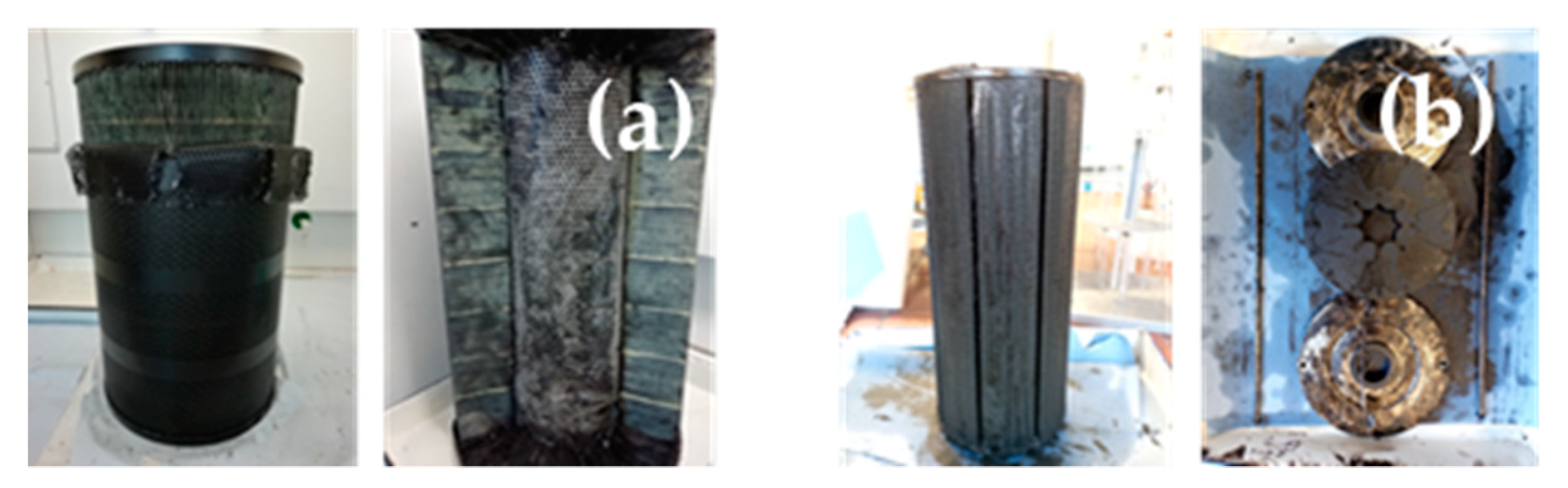
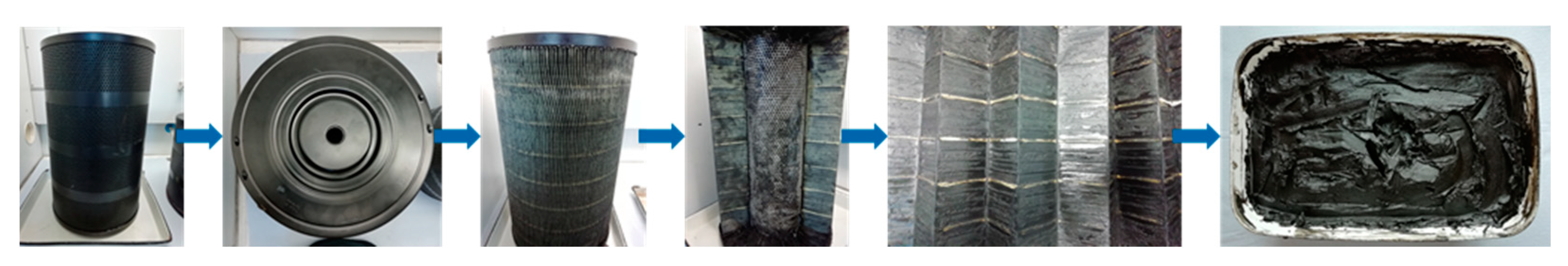
| Filter Cartridge | Dielectric Fluid | Tool Material | EDM Machine | Dimensions d × h [cm] & Mass [kg] | Yield of Sludge [kg] |
|---|---|---|---|---|---|
| (1) SE_01-MT die-sink | synthetic hydrocarbon oil | 99.9% graphite | OPS-Ingersoll Eagle 800 | 30.5 × 50.5 m = 17.09 (wet) | 3.95 (wet) |
| (2) SE_02-AP die-sink | synthetic hydrocarbon oil | 99.9% graphite | GF Machining Solutions | 15.0 × 35.5 m = 5.19 (wet) | 0.46 (wet) |
| Sample/Value | SE_01 Unprocessed | SE_02 Unprocessed | SE_01 Dry Powder | 316L/1.4404 Reference | H11/1.2343 Reference |
|---|---|---|---|---|---|
| x10 (µm) | 0.80 | 0.70 | 8.15 | 22.89 | 19.37 |
| x50 (µm) | 5.21 | 2.16 | 27.52 | 34.66 | 30.08 |
| x90 (µm) | 28.89 | 16.61 | 76.60 | 49.23 | 61.68 |
| circularity | − | − | 0.90 | 0.90 | 0.93 |
| Al (wt%) | Co (wt%) | Cr (wt%) | Cu (wt%) | Mn (wt%) | Mo (wt%) | Ni (wt%) | P (wt%) | Si (wt%) | V (wt%) | C (wt%) | S (wt%) |
|---|---|---|---|---|---|---|---|---|---|---|---|
| (1) 26.88 | 0.53 | 4.34 | 0.57 | 0.65 | 1.04 | 1.13 | 0.06 | 0.46 | 0.33 | n.a. | n.a. |
| (2) − | − | 3.79 | 0.98 | 0.93 | 0.60 | 1.51 | 0.14 | 0.77 | 0.27 | n.a. | n.a. |
| (3) 5.75 | 0.52 | 4.31 | 0.19 | 0.41 | 1.21 | 1.14 | 0.04 | 0.42 | 0.38 | 5.40 | 0.013 |
| (4) − | − | 4.79 | 0.02 | 0.60 | 1.36 | 0.09 | 0.012 | 1.40 | 0.44 | 0.40 | 0.005 |
| (5) − | − | 4.50–5.50 | − | 0.20–0.60 | 1.10–1.60 | − | 0.03 | 0.60–1.25 | 0.25–0.60 | 0.33–0.43 | ≤0.03 |
Publisher’s Note: MDPI stays neutral with regard to jurisdictional claims in published maps and institutional affiliations. |
© 2022 by the authors. Licensee MDPI, Basel, Switzerland. This article is an open access article distributed under the terms and conditions of the Creative Commons Attribution (CC BY) license (https://creativecommons.org/licenses/by/4.0/).
Share and Cite
Voigt, O.; Peuker, U.A. Suitability of Eroded Particles from Die-Sink Electro Discharge Machining for Additive Manufacturing—Review, Characterization and Processing. Metals 2022, 12, 1447. https://doi.org/10.3390/met12091447
Voigt O, Peuker UA. Suitability of Eroded Particles from Die-Sink Electro Discharge Machining for Additive Manufacturing—Review, Characterization and Processing. Metals. 2022; 12(9):1447. https://doi.org/10.3390/met12091447
Chicago/Turabian StyleVoigt, Oliver, and Urs Alexander Peuker. 2022. "Suitability of Eroded Particles from Die-Sink Electro Discharge Machining for Additive Manufacturing—Review, Characterization and Processing" Metals 12, no. 9: 1447. https://doi.org/10.3390/met12091447