Article

Effect of Solidification Variables on the Tensile Property of 2.8 wt% C–26 wt% Cr White Iron

1
Department of Advanced Materials, Changwon National University, Changwon 51140, Korea
2
Jokwang I.L.I. Co., Ltd., Yangsan 618-819, Korea
3
Doosan Enerbility Co., Ltd., Changwon 51711, Korea
4
High Temperature Materials Department, Korea Institute of Materials Science, Changwon 51508, Korea
*
Author to whom correspondence should be addressed.
Metals 2022, 12(9), 1416; https://doi.org/10.3390/met12091416
Submission received: 6 July 2022 / Revised: 23 August 2022 / Accepted: 24 August 2022 / Published: 27 August 2022
(This article belongs to the Special Issue Advanced Solidification Processing and Casting Technologies)

Abstract

:
The present study aimed to investigate the increasing solidification rate during directional solidification developed from in situ composites of M7C3/austenite eutectic, to in situ composites with a small portion of dendrites, and to partial in situ composites with equiaxed structures. M7C3 fibre aligned along the solidified direction in the in situ composites; however, its orientation and shape became irregular among the dendrites. In situ composite structure has higher tensile strength than partial in situ composite or equiaxed material. Crack initiation in the fibre occurred because the fibre could not accommodate the deformation of the matrix under tensile stress. The tensile fracture was caused by both crack initiations in the M7C3 fibre or at the randomly oriented particles, and the crack propagation to matrix.

1. Introduction

High Cr white irons are widely applied to wear-resistant parts due to their high hardness value and excellent wear resistance. Generally, most of the wear-resistant high Cr white irons have a hypoeutectic composition. The microstructure of hypoeutectic high Cr white irons is composed of primary austenite and eutectic structures, depending on chemical composition [1,2,3,4,5]. The fractions of primary austenite and eutectic structures in hypoeutectic high Cr white irons are closely related to carbon equivalent (Ceq) [2].
The high hardness value of high Cr white iron is attributed to the eutectic structure, formed by austenite/M7C3 carbide eutectic reaction. Especially, hard M7C3 carbide increases the hardness and wear resistance of the alloy. The fractions of the existing phases are dependent upon chemical composition (Ceq) and solidification variables [1,2,3,4,5].
The only casting variable in conventional casting is the pouring temperature. It is not easy to measure the solidification rate or thermal gradient at the solid/liquid interface. Thus, control of the solidification variables during conventional casting of the fixed chemical composition is not available. By the way, it is available in directional solidification (DS) by the controls of withdrawal rate from the furnace and thermal gradient at the solid/liquid interface (G). DS processed materials may have various grain structures depending on the solidification rate at a certain thermal gradient (G). The various morphology of grain or phase also have strong effects on the mechanical properties of the material.
Thus, in the present study, the tensile property of 2.8 wt% C–26 wt% Cr white iron has been investigated using DS with various solidification rates, generating various microstructures in comparison with conventional castings.

2. Experimental Procedure

2.1. Specimen Preparation

The chemical composition of the specimen is listed in Table 1, which is in the composition range of ASTM A 532 Class III Type A. The specimens were prepared by induction melting and casting to Y-block. Specimens for the directional solidification and quenching (lower: DSQ) were machined to a rod with a 4.7 mm diameter by electro-discharging wire cutting. DSQ apparatus (Assembled in Changwon National University, Changwon, Korea) is composed of a heating furnace in the upper part, an insulating zone in the middle, water cooling part in the lower part, and a water bath at the bottom. The apparatus is a kind of modified Bridgeman furnace.
The EDM machined rod (4.7 mm diameter and 100 mm length) was polished to remove the oxidized layer at the surface. Then, the rod was inserted into an alumina tube (ID 5 mm × OD 8 mm × L 700 mm). The alumina tube was installed in the DSQ apparatus. The alumina tube was evacuated by a rotary vacuum pump followed by a 99% Ar gas purge three times to make the inactive atmosphere.
The specimens were heated to 1600 °C and soaked for 30 min for stabilization. Then, the specimens were directionally solidified (DS) at a constant thermal gradient of 10 K/mm, and at various solidification rates of 1, 5, 10, 25, and 50 µm/s. In order to keep the solid/liquid interface at each solidification rate, the alumina tube was quenched into the water bath at the bottom of the apparatus. The DS specimens were machined to sub-size tensile specimens according to ASTM E8M. The specimens for the tensile test were subjected to heat treatment, as shown in Figure 1.

2.2. Microstructural Observation and Mechanical Tests

Specimens for optical microscopy (OM: Nikon/ECLIPSE MA200, Tokyo, Japan) and scanning electron microscopy (SEM: JEOL/JSM–IT500LV, Tokyo, Japan) were prepared metallographically and etched by swabbing with Vilella’s reagent consisting of 45 mL glycerol, 15 mL nitric acid, and 30 mL hydrochloric acid. The DSQ specimens were prepared parallel and normal to the solidification direction with the same etchant.
Specimens for Electron Backscattered Diffraction (SEM: HITACHI SU6600 (Schaumbury, IL, USA) and EBSD: EDAX-TSL (Draper, UT, USA) were prepared by mechanical polishing with a 0.04 μm colloidal silica suspension of low stress grinding to prevent residual stress on the surface. The growth directions of the dendrite and M7C3 carbide were distinguished by the color of the grain map.
Tensile tests of the conventional cast specimen and the DS specimens were conducted at the universal testing machine (UTM, Instron 5982, Norwood, MA, USA). Tensile tests were carried out to understand the difference in tensile curves among the condition. Tests were carried out three times for each condition, and the representative results were displayed in the next section.
The strength of existing phases was indirectly measured using a Vickers hardness tester (HM-21, Mitutoyo, Kawasaki, Japan) under 200 g weight.

3. Results and Discussions

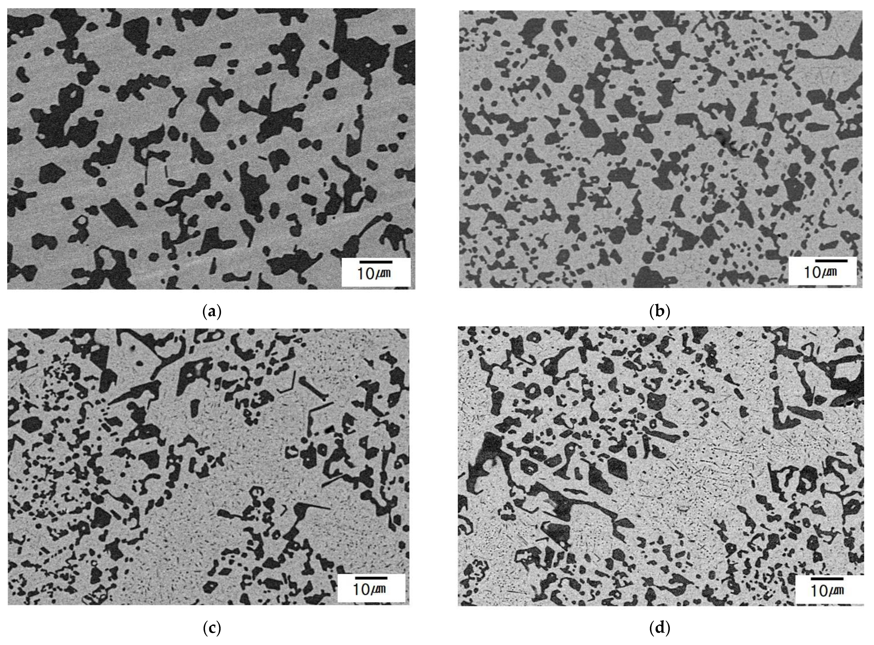
3.1. As-Cast Microstructure

The microstructure of conventionally cast hypoeutectic high Cr white iron has a poly-crystalline structure and is composed of primary austenite dendrites and a eutectic structure. Additionally, 2.8 wt C%–26 wt% Cr white iron has the typical microstructure of primary austenite dendrite and eutectic (austenite/M7C3 carbide) structure, as shown in Figure 2.
Directional solidification of the material developed various microstructural features depending on the solidification rate. The solid/liquid interface morphology developed from plane front to protruded wavy shape with increasing solidification rate. Only austenite/M7C3 eutectic structure existed in the solid portion at and lower solidification rate 10 μm/s, which has a plane front interface, however at and higher solidification rate of 25 μm/s primary austenite dendrite existed, as shown in Figure 3c in comparison with randomly oriented dendrites in equiaxed material in Figure 3a. Especially, the primary austenite dendrite locates close to the solid/liquid interface in the solid. It was confirmed through the calculation of the solidus of each phase by the authors. The primary austenite at the solidification rate of 50 μm/s in Figure 3d could not grow directionally. However, they grew in random orientations because primary austenite formed at a higher temperature than that of the austenite/M7C3 eutectic phase.

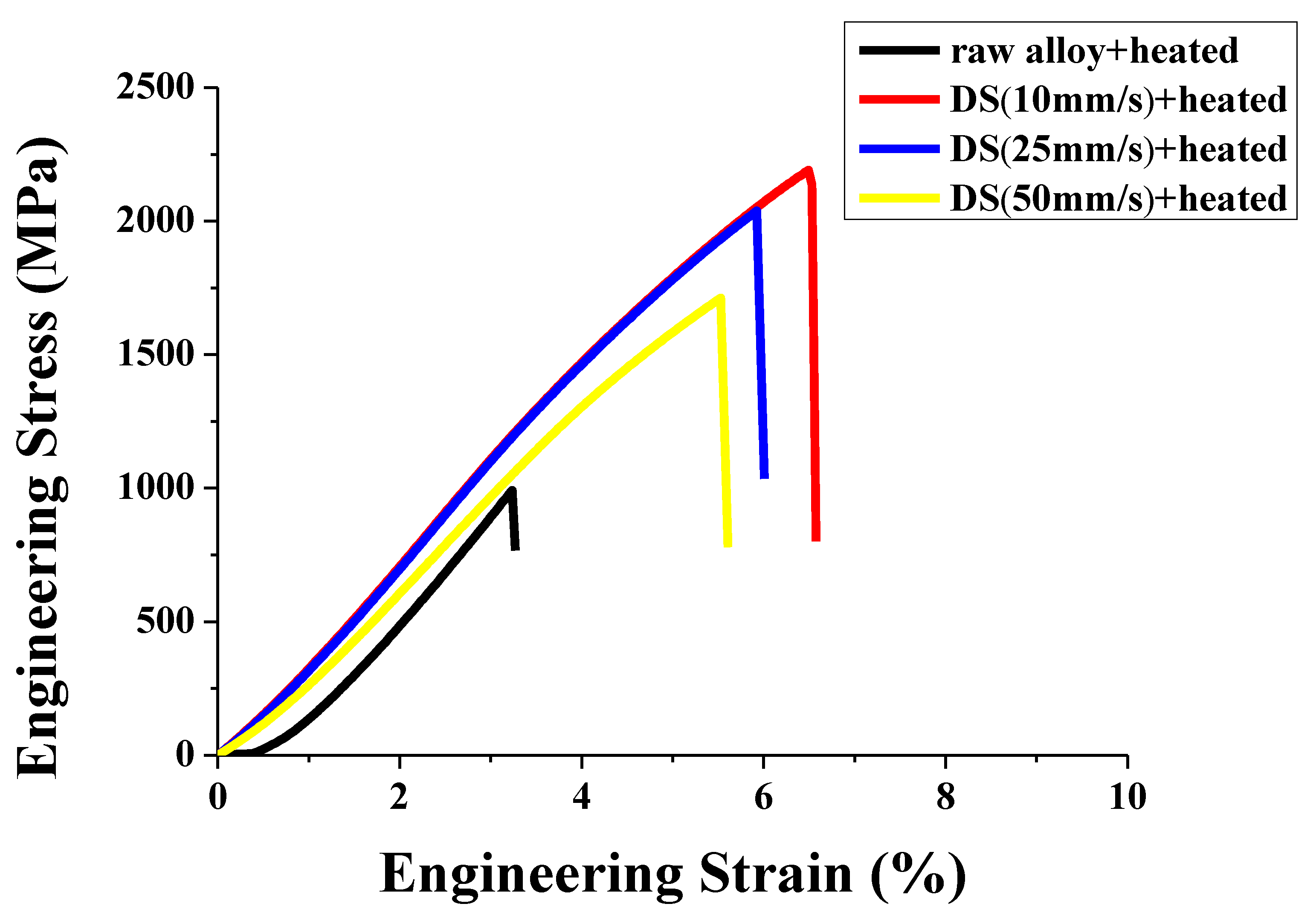
3.2. Tensile Properties

Conventionally cast equiaxed specimens and the DS specimens were subjected to heat treatment in Figure 1. The heat-treated specimens were machined to sub-size tensile specimens according to ASTEM E 8M. Tensile test results are displayed in Figure 4. The DS specimens with the lower solidification rate had a higher tensile strength. As mentioned above, DS specimens which were solidified at and higher than the 25 μm/s have dendrites with eutectic structures, and those solidified at and lower than 10 μm/s have fully eutectic structure. All the specimens showed little or no plastic deformation behavior, as displayed in the stress-strain curves in Figure 4, and it is presumably attributed to the nature of the alloy that has hard M7C3 carbide and martensite matrix (transformed from austenite). The stress strain curve of DS specimens solidified at 10 μm/s, and that of those at 25 μm/s showed similar behavior except for a difference in strength. And the specimen solidified at 50 μm/s has lower strength than that solidified at 25 μm/s. The equiaxed specimen showed the lowest tensile strength among the specimens. The primary austenite dendrite fraction increases with increasing solidification rate at and higher 25 μm/s.
Tensile strength decreased with increasing solidification or primary austenite dendrite fraction or decreasing eutectic structure fraction. Except for the difference in ultimate tensile fracture strength, all the specimens showed similar elastic tensile behavior in the stress-strain curve. It means that the tensile behavior of the specimens was governed by the non-deformable hard phase. The eutectic composition of high Cr white iron has a phase fraction ratio of austenite: M7C3 = 2.76:1 [2]. As appeared in Figure 4, the microstructure of the DS specimen solidified at and lower than 10 μm/s is a fully austenite/M7C3 eutectic structure. The typical microstructure of the DS specimen is displayed in Figure 5. The phases grew along the solidification direction (Figure 5a) and distributed relatively uniformly at a low solidification rate (Figure 5b). The feature of the microstructure is austenite/M7C3 in situ composites, similar to (Co, Cr)–Cr7C3 in situ composite [6]. The ultimate tensile stress of the in situ composite is rigorously given by the Rule of Mixtures, the average of the individual phases [6]. The tensile and fracture behavior is dependent upon the strength and volume fraction of individual phases [6].
(1)
if σmVm > σfVf: matrix carries most of the stress, thus fibre failure does not influence neighbouring fibres;
(2)
if σmVm < σfVf: when fibre breaks, the crack rapidly propagates through the matrix to fracture neighbouring fibres;
where, σm—matrix strength; Vm—matrix volume; σf—fibre strength, and Vf—fibre volume.
The strength of each phase was indirectly measured by Vickers hardness number (VHN) in the as-cast condition to exclude M23C6 precipitation in austenite in the as-heat treated conditions: M7C3; 1600~1850, matrix; 390~450 [2,3,4].
Based on the hardness value, the strength of the M7C3 is higher than that of the matrix. Thus, the tensile fracture behavior of the eutectic in situ composite is in the above case 2) of McLean’s rule [6].
The tensile strength of the materials decreased with increasing solidification rate at and above 25 μm/s. Microstructure solidified at and lower than 10 µm/s is in situ composite of eutectic phase. However, at and above 25 µm/s is the mixture of the in situ eutectic phase and primary austenite (transformed to martensite at room temperature) dendrite as displayed in Figure 4 and Figure 6.
In situ composite structure sustained in the specimen solidified at and lower than 10 µm/s, partial in situ composite and dendrite existed at 25 µm/s, and solidification at 50 µm/s resulted in a little in situ composite and dendritic structure.
Tensile behavior of the material is presumably related to the existence of eutectic in situ composite, which aligns M7C3 carbide parallel to the solidified direction, and to the matrix orientation, which aligns according to Kurdjumov–Sachs relationship [7] at room temperature. Generally, FCC materials preferentially solidify in [1]. Thus, the grains in the DS specimens were solidified along the orientation, and then the following martensitic transformation aligned the grains according to the Kurdjumov–Sachs relationship. Normally, the growth of hexagonal M7C3 carbide perpendicular to the (0001) basal plane is faster than that in other planes [8]. Unlike matrix, the M7C3 carbide does not have phase transformation after solidification. Thus, the M7C3 keeps the same orientation at room temperature. In the in situ composites, the M7C3 fibre aligned parallel to the solidification direction along [1] orientation. However, the M7C3 grew in random orientation and irregular shape in the materials with dendrites, such as equiaxed or dendritically solidified materials. The dendrite area means loss of in situ composite structure, and the remaining eutectic structure keeps in situ composite structure. EBSD maps revealed the orientation difference between M7C3 carbides in the interdendritic region and those in situ composite, as shown in Figure 7.
The tensile property of the material might be influenced by the loss of in situ composite structures at the higher solidification rate. This was revealed by the microstructural observation at the fractured tip of tensile specimen. Different fracture behavior appeared among the equiaxed, and the DS specimens as displayed in Figure 8 and Figure 9.
Fully in situ composite of eutectic structure in Figure 8b, slight less in situ composites in Figure 8c, partially in situ composites with some portion of dendrite in Figure 8d, and no in situ composites of the fully random array of eutectic phase and dendrites are displayed. Crack initiated preferentially at the M7C3 aligned normal to tensile stress direction as appeared in Figure 8a,d. It is clear in Figure 9. Fully equiaxed in Figure 9a clearly shows the preferential crack initiation at the M7C3 normal to stress direction. In Figure 9d, cracks are preferentially initiated at the M7C3 among the secondary dendrites (indicated by arrows). Several cracks were initiated in the longitudinal M7C3 fibres in situ composite of Figure 9b,c. Crack initiation in the M7C3 fibre was associated with deformation bands (or slip bands) in the matrix, as indicated by arrows in Figure 9b. Thus, crack initiation was presumably caused by the hardness difference between relatively hard fibre (~1700 VHN) and the deformable matrix ~400 VHN). The fibre could not accommodate the deformation of the matrix under tensile stress. Thus, the crack directions in the fibre are almost parallel to that of the deformation band in the matrix, as shown in Figure 9b.
As McLean explained, when fibre of high strength breaks, the crack rapidly propagates through the matrix to fracture neighbouring fibres [6]. The initiated cracks in the fibre are supposed to be propagated through the matrix to fracture neighbouring fibres, as displayed in Figure 8 and Figure 9b,c.

4. Conclusions

Effects of solidification variables on microstructural evolution and the tensile property of 2.8 wt% C–26 wt% Cr white iron were studied by directional solidification and quenching experiment. The conclusions are as follows:
  • Primary austenite dendrite (~25 vol%) existed in the mother alloy; however, it did not develop primary austenite dendrite with slow solidification at and lower 10 µm/s. However, primary austenite dendrite increased with increasing solidification rate at and higher 25 µm/s.
  • In situ composite structure of M7C3/austenite eutectic formed with slow solidification at and lower 10 µm/s. The fraction of in situ composites decreased with increasing solidification rate. The orientation and shape of the M7C3/austenite eutectic phase among secondary dendrite became irregular in the solidified regions.
  • In situ composite structure has higher tensile strength than partial in situ composite or equiaxed material. Crack initiation in the fibre occurred because the fibre could not accommodate the deformation of the matrix under tensile stress.
  • Tensile fracture was caused by both crack initiations in the M7C3 fibre or randomly oriented particles and crack propagation to the matrix.

Author Contributions

Conceptualization, C.-Y.J. and J.-H.L.; methodology, C.-Y.J. and J.-H.L.; software, D.-W.J. and J.-H.S.; validation, J.-H.S.; formal analysis, D.-W.J.; investigation, C.-Y.J.; resources, C.-Y.J. and J.-H.L.; data curation, D.-W.J.; writing—original draft preparation, C.-Y.J. and J.-H.L.; writing—review and editing, C.-Y.J. and J.-H.L.; visualization, I.-Y.J.; supervision, I.-S.K. and J.-H.L.; project administration, C.-Y.J. and J.-H.L.; funding acquisition, J.-H.L. All authors have read and agreed to the published version of the manuscript.

Funding

MOTIE 20214000000480, Development of R&D engineers for combined cycle power plant technologies.

Data Availability Statement

Data presented in this article are available at request from the corresponding author.

Acknowledgments

This work was supported by the Korea Institute of Energy Technology Evaluation and Planning (KETEP) grant funded by the Korea government (MOTIE) (20214000000480, Development of R&D engineers for combined cycle power plant technologies).

Conflicts of Interest

The authors declare no conflict of interest.

References

  1. Davis, J.R. Metallurgy and Properties of High-Alloy White Irons. In ASM Specialty Handbook Cast Irons, 1st ed.; ASM International: Novelty, Oh, USA, 1996; pp. 111–122. [Google Scholar]
  2. Oh, J.S.; Song, Y.G.; Choi, B.G.; Bhamonsut, C.; Nakkuntod, R.; Jo, C.Y.; Lee, J.H. Effect of dendrite fraction on the M23C6 precipitation behavior and the mechanical properties of high Cr white irons. Metals 2021, 11, 1576. [Google Scholar] [CrossRef]
  3. Song, Y.G.; Oh, J.S.; Choi, B.G.; Jo, C.Y.; Lee, J.H. Effects of primarily solidified dendrite and thermal treatments on the M23C6 precipitation behavior of high Cr white iron. Metals 2021, 11, 1690. [Google Scholar] [CrossRef]
  4. Pearce, J.T.H. High chromium cast irons to resist abrasive wear. Foundryman 2002, 95, 156. [Google Scholar]
  5. Tabrett, C.P.; Sare, I.R.; Ghomashchi, M.R. Microstructure-property relationship in high chromium white iron alloys. Int. Mater. Rev. 1996, 41, 59–82. [Google Scholar] [CrossRef]
  6. McLean, M. Directionally solidified materials for high temperature service. Met. Soc. 1983, 19, 207–256. [Google Scholar]
  7. Yardley, V.A.; Payton, E.J. Austenite-martensite/bainite orientation relationship: Characterization parameters and their application. Mater. Sci. Technol. 2012, 30, 1125–1130. [Google Scholar] [CrossRef]
  8. Ma, S.; Xing, J.; He, Y.; Li, Y.; Huang, Z.; Liu, G.; Geng, Q. Microstructure and crystallography of M7C3 carbide in chrome cast iron. Mater. Chem. Phys. 2015, 161, 65–73. [Google Scholar] [CrossRef]
Figure 1. Heat treatment cycle.
Metals 12 01416 g001
Figure 2. Optical micrographs of 2.8 wt% C–26 wt% Cr white iron showing poly crystalline and mixed structure of primary austenite and eutectic phase.
Metals 12 01416 g002
Figure 3. Micrographs normal to the solidified direction. (a) equiaxed mother alloy; (b) 10 μm/s; (c) 25 μm/s; (d) 50 μm/s.
Metals 12 01416 g003
Figure 4. Tensile test stress-strain curve of each specimen.
Metals 12 01416 g004
Figure 5. Typical micrographs of DS specimen solidified at 1 μm/s. (a) parallel to the solidification direction; (b) normal to the solidification direction.
Metals 12 01416 g005
Figure 6. Micrographs normal to the solidified direction. (a) 1 μm/s; (b) 10 μm/s; (c) 25 μm/s; (d) 50 μm/s.
Metals 12 01416 g006
Figure 7. EBSD maps of DS specimen with dendrites showing orientation difference of M7C3 carbides in the eutectic in situ composite (arrow indicates) and those in the interdendritic region. (a) grain map; (b) image quality; (c) phase map.
Metals 12 01416 g007
Figure 8. Microstructure at fractured tip of tensile specimen (a) equiaxed mother alloy (b) 10 μm/s (c) 25 μm/s (d) 50 μm/s.
Metals 12 01416 g008
Figure 9. Micrographs showing tensile crack initiations (a) equiaxed mother alloy (b) 10 μm/s (c) 25 μm/s (d) 50 μm/s. The blue arrows indicate slip band formed under tensile stress.
Metals 12 01416 g009
Table 1. Chemical composition of the specimen wt%.
Chemical CompositionCSiMnNiCrMoFe
ASTM A532 Class III
Type A
2.0~3.31.5 max2.0 max2.5 max23.0~30.03.0 maxbal.
Specimen2.810.60.640.1626.0-bal.
Publisher’s Note: MDPI stays neutral with regard to jurisdictional claims in published maps and institutional affiliations.

