Article

Fabrication of Mg/Al Clad Strips by Direct Cladding from Molten Metals

1
Graduate School of Advanced Science and Technology, Tokyo Denki University, Ishizaka, Hatoyama-machi, Hiki-gun, Saitama 350-0394, Japan
2
Division of Mechanical Engineering, Tokyo Denki University, Ishizaka, Hatoyama-machi, Hiki-gun, Saitama 350-0394, Japan
3
Department of Mechanical Engineering, Osaka Institute of Technology, 5-16-1 Omiya Asahi-ku, Osaka 535-8585, Japan
*
Author to whom correspondence should be addressed.
Metals 2022, 12(9), 1408; https://doi.org/10.3390/met12091408
Submission received: 1 August 2022 / Revised: 22 August 2022 / Accepted: 23 August 2022 / Published: 25 August 2022
(This article belongs to the Special Issue Casting and Forming of Light Alloys)

Abstract

:
This work describes the fabrication of AZ91D/A5052 clad strips by direct cladding from molten metals using a horizontal twin roll caster. Subsequently, the effects of roll speed, pouring sequence, and solidification length on the AZ91D/A5052 clad strips were investigated. The AZ91D/A5052 clad strips with a thickness of 4.9 mm were successfully cast at a roll speed of 9 m/min and with a 5 mm roll gap. The cladding ratio of AZ91D/A5052 was about 1:1. The single-roll casting results showed that the experimental solidification constants of AZ91D and A5052 were 62 mm/min0.5 and 34 mm/min0.5, respectively. The twin-roll casting results showed that the effect of rolling speed on the surface condition of A5052 was greater than that of AZ91D. In addition, the high melting point A5052 alloy poured into the lower nozzle could solve the remelting problem of the low melting point AZ91D. Moreover, extending the upper solidification distance could reduce the generation of intermetallic compounds. The EDS analysis results showed no voids at the bonding interface, while three intermetallic compound layers were also found at the bonding interface of AZ91D/A5052 strips, namely α-Mg + Mg17Al12, Mg17Al12, and Al3Mg2. This study could be instructive for dissimilar sheet metal bonding.

Graphical Abstract

1. Introduction

Automotive light-weighting has been a hot research topic in recent years to improve fuel efficiency and reduce vehicle exhaust emissions [1,2,3,4]. Traditional automotive lightweighting technology has been used to replace steel materials with a single lightweight alloy [5]. However, with the development of new energy vehicles, the characteristics of single-metal materials can no longer meet the new demands of automotive industry development. On this basis, metal additive manufacturing technologies have also started to receive attention [6,7,8,9]. Among these, the fabrication of clad sheets has become a current research hotspot [10,11,12,13,14], as they will exhibit the characteristics of each metal alloy, and can realize the complementary advantages and disadvantages of different metal alloys.
As the lightest metal among the practical structural metals, magnesium (Mg) alloys have gained attention as they offer excellent specific strength, vibration damping performance, and recyclability. However, drawbacks such as low corrosion resistance and high production costs have limited their application in the automotive industry [15]. As one of the practical lightweight metals, aluminum (Al) alloys have been widely used in the transportation and aerospace fields due to their active chemical properties, which can easily react with oxygen in the air to produce a dense oxide film and improve their corrosion resistance. Composite sheets prepared by using Mg and Al alloys can improve the corrosion resistance of Mg alloys, while also endowing the composite sheets with the physical properties of two metal sheets [16].
Many preparation methods for Mg/Al composite sheets have been reported, such as vacuum diffusion bonding [17], in situ hot press bonding [18], cold rolling [19], hot rolling [20,21,22,23,24], explosion welding [25,26,27,28,29], and solid-liquid composites [30,31]. The vacuum diffusion bonding method consists of bonding Mg and Al sheets by heating, pressurizing, and cooling in a vacuum environment. Because oxides on the metal surface can hinder diffusion bonding, it is necessary to clean the oxides before experimentation; however, this method is tedious and has high equipment requirements [17]. Jin investigated an in situ hot press bonding technique to prepare Mg/Al composite sheets. This technique required only four steps, and no vacuum environment or protective gas was needed to avoid oxidation of the metal material. The results showed that the Mg/Al composite sheet had good interfacial strength, while the intermetallic compounds that were generated at the interface had little effect on the Mg/Al composite sheet in compression, but caused clad–core delamination under tensile conditions [18]. Cold and hot rolling is a combination of pressure on Mg and Al alloy sheets using rolling equipment. The advantage of this approach is the low production cost and the fact that the preparation process does not need to be performed under a vacuum. In addition, most of the Mg/Al composite sheets are rolled by hot rolling because of the difficulty of processing Mg alloys at room temperature. Generally, rolled Mg/Al composite sheets also must be annealed. Research has shown that the best bonding strength of Mg/Al composite plates can be achieved under an annealing temperature of 200 °C and annealing time of 1 h [21]. Cao et al. investigated the effect of secondary rolling on the interfacial bonding strength and mechanical properties of Al/Mg/Al composite sheets. The results showed that secondary rolling significantly improved the interfacial bond strength. After annealing, the elongation of the composite plate was as high as 21% and the interfacial strength was maintained at 12 MPa [24]. Explosion welding uses the high impact forces generated by the explosion to strongly bond Mg and Al alloy sheets. Wang et al. improved the explosion welding technique by adding an additional thin aluminum plate as a buffer layer between the Mg and Al sheets, while the other sides of the magnesium sheets were fixed with steel plates to avoid deformation. The welding process was also simulated using smoothed-particle hydrodynamics (SPH) simulations, and the bonding interface showed a regular wave shape, which was in agreement with the experimental results [28]. However, explosion welding poses certain safety risks and cannot be produced on a large scale. Solid-liquid composite uses twin-roll casting technology, which differs from traditional sheet production methods in that it significantly reduces production costs due to the use of a twin-roll caster, enabling continuous casting from molten metals. Park et al. successfully fabricated three-layer A5052/AZ31/A5052 clad strips by twin-roll casting and post-treatment, where the thinness of the A5052 alloy sheet resulted in an uneven surface condition of the composite sheet after casting [31]. In addition, Haga et al. successfully cast clad strips consisting of Al alloys in one step using a single-roll caster equipped with a scraper and an unequal diameter twin-roll caster. A theoretical formula for controlling the clad ratio by solidification length is also proposed. Because the second molten metal was located directly over the free solidification surface of the first molten metal, oxidation of the first metal as a result of contact with air was avoided [32,33]. However, relatively little research has been conducted on the liquid–liquid lamination of dissimilar metals.
In this study, AZ91D/A5052 clad strips were fabricated by direct cladding from molten metals using horizontal twin-roll casters, and the effects of experimental parameters such as the roll speed, pouring sequence, and solidification length on the surface conditions of the AZ91D/A5052 strips were investigated. Then, the microstructure of the fabricated strips was investigated using optical microscopy and electron microscopy.

2. Experimental Procedures

2.1. Materials and Methods

An AZ91D Mg alloy (Mg-9mass%Al-1mass%Zn alloy), with excellent specific strength, was chosen as the base material, and an A5052 Al alloy (Al-2.5mass%Mg alloy) with good corrosion resistance and plasticity was chosen as the covering material. Table 1 shows the chemical compositions of the AZ91D and A5052 alloys. Figure 1 shows a schematic illustration of the cladding processes of the two molten metals, which utilized a horizontal twin-roll caster (HTRC). The two molten metals were poured into the upper and lower nozzles separately, cooled rapidly when they made contact with the rolls, and then bonded between the rolls. The rolls were composed of copper and were 300 mm in diameter and 150 mm in width. In addition, both the upper and lower nozzles had a width of 150 mm.

2.2. Control of Clad Ratio

In this study, because molten metal B in the lower nozzle solidifies before the molten metal A in the upper nozzle, the cladding ratio of the cladding material could be expressed by Equation (1), where the roll gap was the shortest distance between the surfaces of the twin rolls:
clad   ratio = roll   gap   -   thickness   of   solidification   layer   of   molten   metal   B   thickness   of   solidification   layer   of   molten   metal   B ,
The thickness of the solidification layer of molten metal B was controlled by the solidification length and roll speed, and the thickness of the solidification layer is given by Equation (2) [32]:
d = K t = K L / V ,
where d is the thickness of the solidification layer, K is the experimental solidification constant, t is the solidification time, L is the solidification length, V is the roll speed, and the K values were obtained from single-roll casting experiments. The schematic diagram of the single-roll casting experiment is shown in Figure 2, and the experimental conditions are shown in Table 2. The length of the molten metal in the lower nozzle in contact with the roll was defined as the solidification length (L), and the length of the molten metal in contact with the roll after completion of solidification was defined as the cooling length (Lc). The pouring temperature was the temperature of the molten metal inside the crucible during pouring, while the casting temperature was the temperature of the molten metal inside the nozzle. Because the temperature of the molten metal decreased as a result of the pouring process, the pouring temperature was increased by 5 °C to ensure that the temperature inside the nozzle reached the liquidus temperature of the metal material [34]. Because it was difficult to measure the temperature of the bonding interface in the twin-roll composite casting, the surface temperature of the solidified metal immediately out of the melt pool was measured in the single-roll casting experiment. The temperature at point A was approximately equal to the temperature of the metal bonding surface on the lower roll side before the two metals were compounded. The temperature of the metal contact surface on the upper roll side was its liquidus temperature. In addition, the continuous twin-roll caster used in this experiment was not equipped with water cooling. To investigate the variation of the surface temperature of the cast rolls, the surface temperature of point B during the casting process was measured.

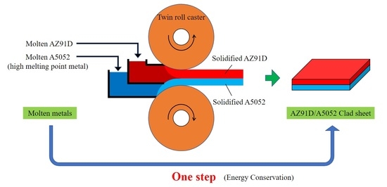
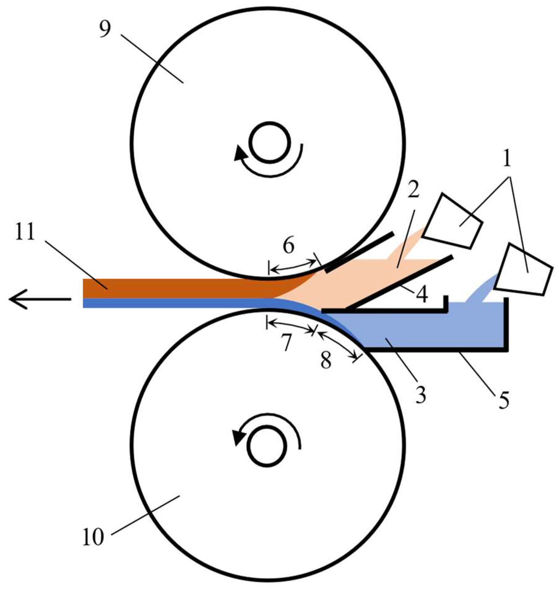
2.3. Cladding for Mg/Al Clad Strips by Twin-Roll Caster

The casting conditions for the Mg/Al clad strips are shown in Table 3. The experimental results of single-roll casting showed that the effect of roll speed on the thickness of the solidified layer was small when the roll speed exceeded 12 m/min. Therefore, in this experiment, to study the effect of rolling speed on the Mg/Al clad strip, casting experiments were conducted at rolling speeds ranging from 6–12 m/min, and different pouring sequences were also investigated. In addition, the settings of cooling length and solidification length were kept the same as for single-roll casting, and both were set to 50 mm. The roll gap was set at 5 mm. Because flame retardant gases such as SF6 will destroy the ozone layer and cause environmental pollution, in this experiment, we did not use a flame retardant gas such as SF6. To inhibit the oxidation and combustion of Mg alloys, 0.5 mass% flux (S.K.No.101, TACHIGAWACAST, Japan) was added during the dissolution and refining stages, and an oxide film formed on the surface of the crucible at the end of refining. This oxide film could prevent direct contact between the molten Mg alloy and the oxygen in the air, preventing further oxidation and combustion. In addition, the oxide film was removed from the surface before the Mg alloy was poured. In this study, the molten metal from the upper nozzle was poured directly onto the surface of the metal solidified by the lower nozzle, avoiding direct contact between the lower nozzle metal and the air. This replaced the traditional vacuum environment of hot rolling bonding. The aim of this work was to maximize the control of strip production costs.

2.4. Microstructure of the Bonding Interface

Subsequently, the bonding interface microstructure of the AZ91D/A5052 clad strip was observed using an OLYMPUS BX60M optical microscope. To clearly observe the diffusion layer of the bonding interface, the observation surfaces of the specimens were abraded in turn using #400, #800, #1500, and #2000 sandpaper. The specimens were then polished to a mirror finish using 6.0 and 0.25 µm diamond polishing solutions, in order. Then, the polished surface was sequentially chemically etched with a citric acid solution (10 g of C6H8O7 + 90 g of H2O) and sodium hydroxide solution (1 g of NaOH + 100 mL of H2O). Then, the composition of the intermetallic compounds at the bonding interface was analyzed by ultra-low acceleration voltage scanning electron microscopy (JSM-7100F).

3. Results and Discussion

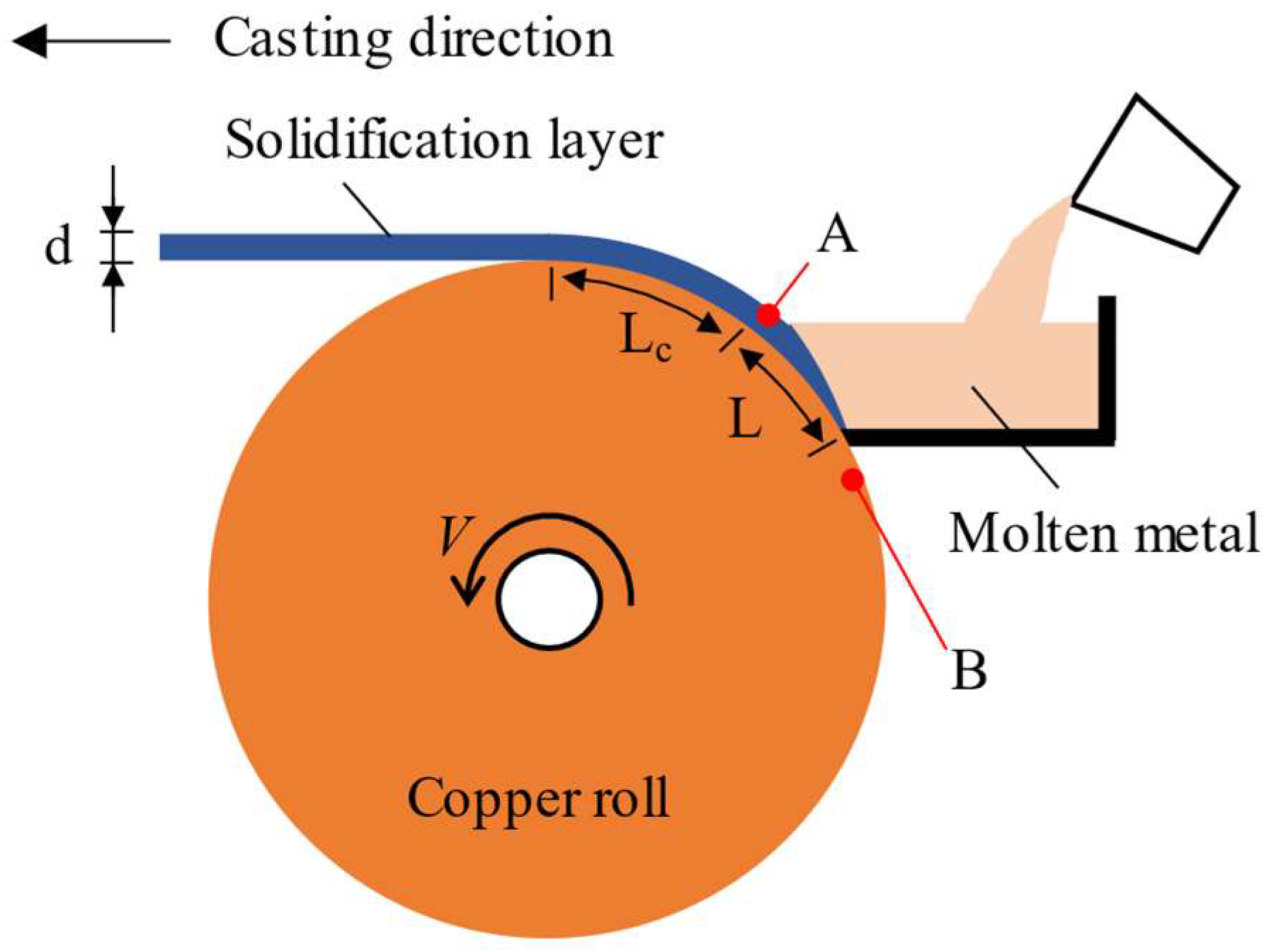
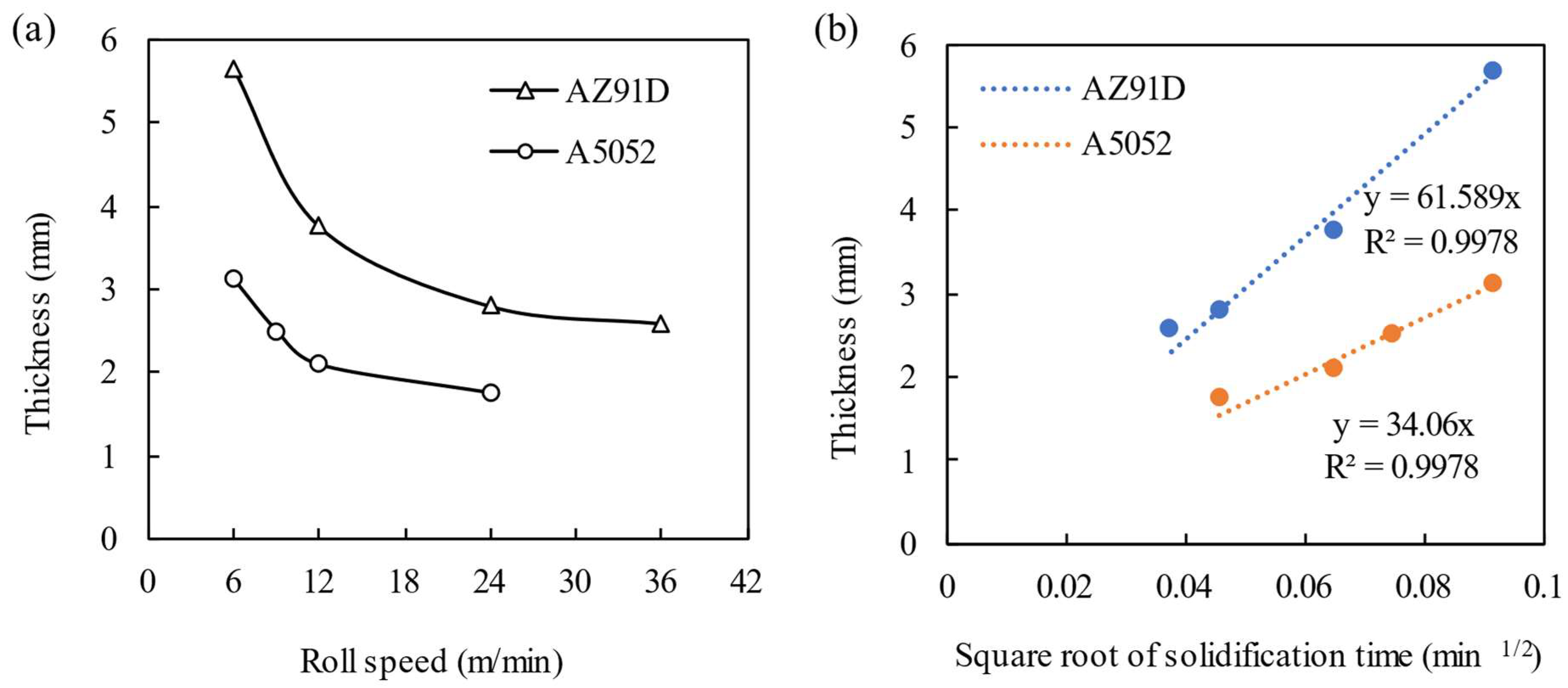
3.1. Calculation of the Experimental Solidification Constants

The temperature measurement results at point A showed that the surface temperature of AZ91D was between approximately 491 °C and 520 °C, while the surface temperature of A5052 was between approximately 600 °C and 626 °C. Because the metal surface was in a semi-solidified state, the thermocouple did not perfectly measure most of the surface temperature of the metal. Therefore, the measured temperature could only be used as a reference. In addition, during the experiment, the temperature at point B increased from the initial 22 °C to 30 °C. Compared to the temperature of the molten metal, the effect of this temperature difference was negligible.
The experimental results showed that AZ91D and A5052 could be cast continuously using a single roll, and the average thickness of the solidification layer was measured using a micrometer. The relationship between the roll speed and solidified layer thickness is shown in Figure 3a. With a higher roll speed, the thickness of the solidification layer was thinner [35]. The effect of the roll speed on the solidified layer thickness was more obvious when the roll speed was below 12 m/min, which indicated that the control of the solidified layer thickness of molten metal B, and consequently the cladding ratio of the cladding material, was easier to achieve under roll speed conditions below 12 m/min. The relationship between the square root of the solidification time and the solidification layer thickness is shown in Figure 3b. According to the figure, the experimental solidification constants of AZ91D and A5052 were 62 mm/min0.5 and 34 mm/min0.5, respectively.
The duration of the experiment was difficult to quantify. Currently, we have observed the approximate time from the pouring to the end of casting by video, which was not accurate. This made it difficult to quantify the duration of the experiment because the amount of molten metal poured at the beginning potentially did not reach the height of the melt pool, and the amount of molten metal in the melt pool slowly decreased after the end of pouring, resulting in thin ends at the front and back of the continuous sheet, with uniformity in the middle. In addition, calculating the solidification time was reasonable. For example, when the roll speed was 6 m/min, the solidification time was 0.5 s for a solidification length of 50 mm, assuming no relative sliding of the solidified molten metal and casting roll.

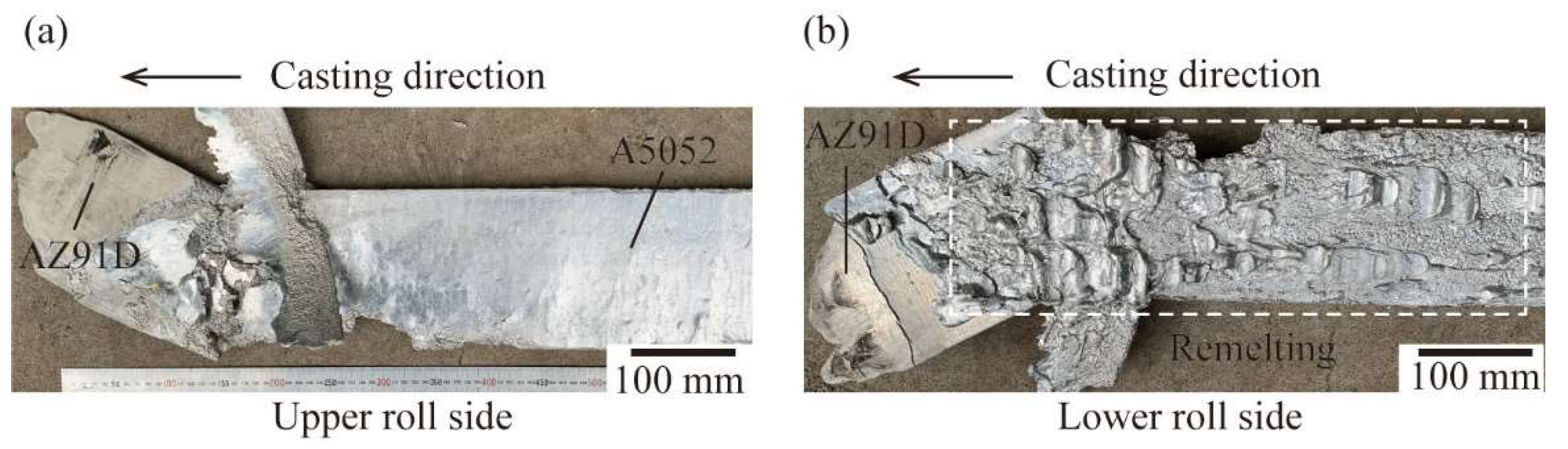
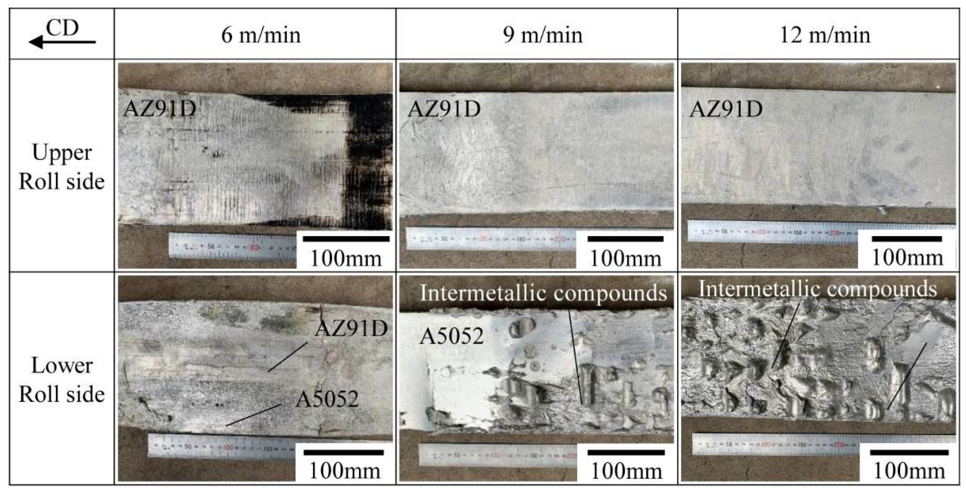
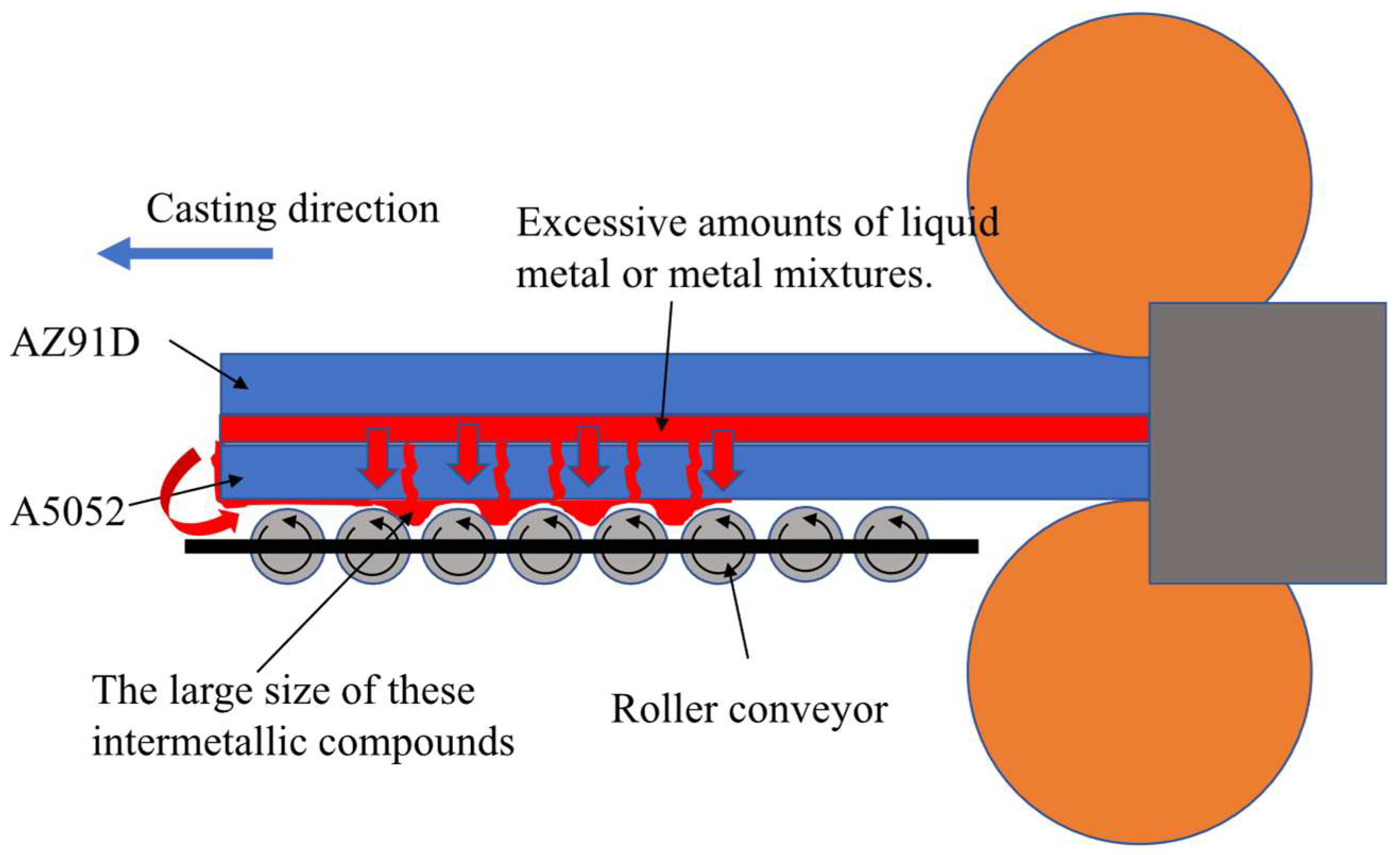
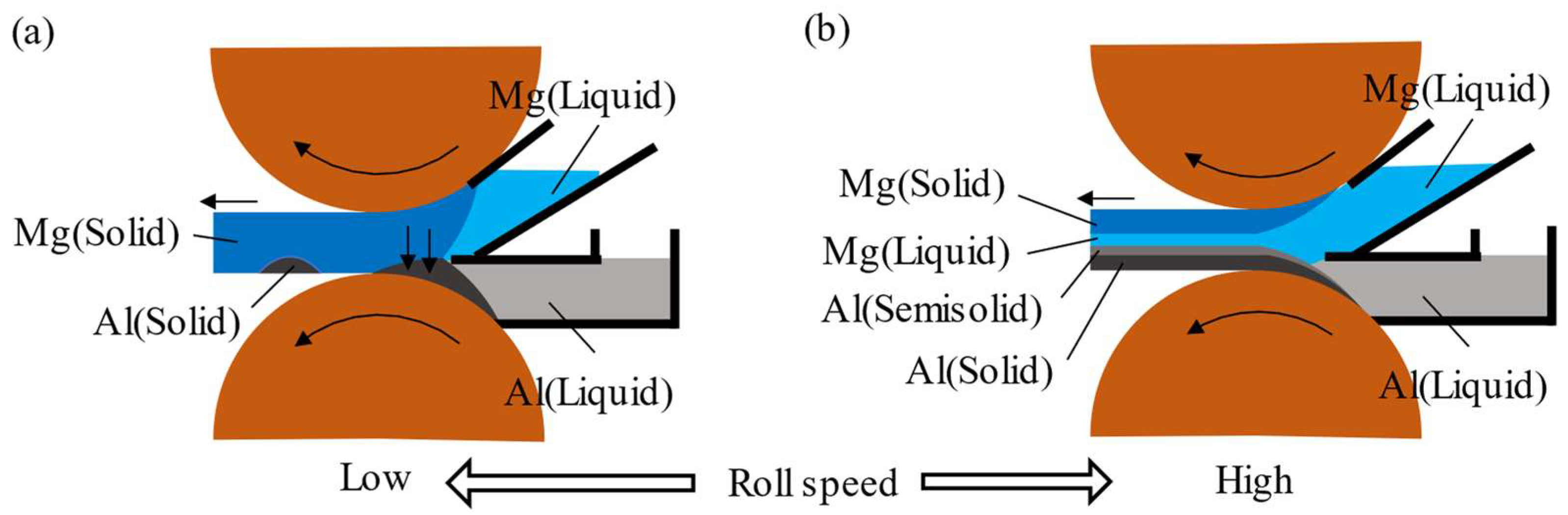
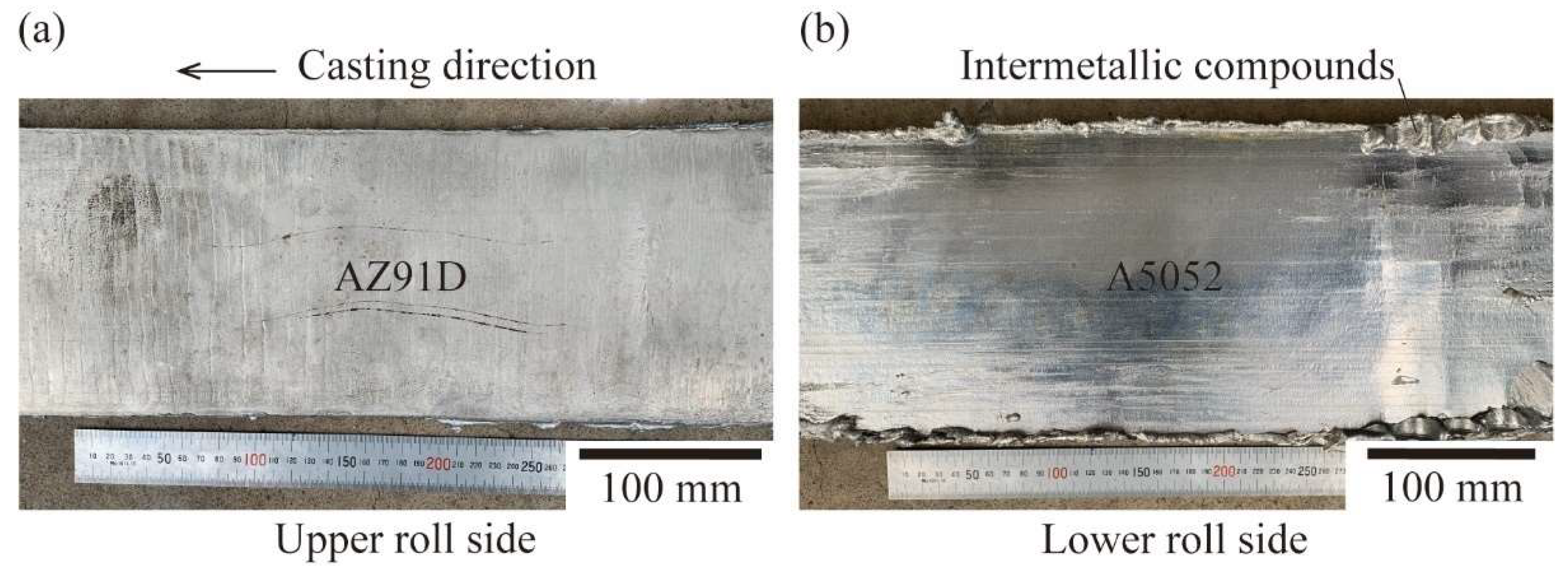
3.2. Effects of Roll Speeds and Pouring Sequences on the Surfaces of the Clad Strips

The experimental results under different roll speeds and pouring sequences are shown in Table 4. The first pouring sequence involved pouring the high melting point A5052 material into the upper nozzle and the low melting point AZ91D material into the lower nozzle. As a result, the remelting of AZ91D on the lower roll side occurred under different roll speed conditions, as shown in Figure 4, which also shows the experimental results of the first pouring sequence at a roll speed of 9 m/min. The upper roll contact surface of the strip showed a good surface condition; however, the lower roll contact surface was uneven. The front portions of the clad strips showed that it was possible to form AZ91D sheets without the A5052 covering. After A5052 covered the AZ91D layer, the underlying AZ91D was dissolved and mixed together, forming grey intermetallic compounds. In addition, two types of heat transfer were associated with AZ91D in this experiment: one with A5052, and the other with the lower copper roll. Because the solidus temperature of A5052 was higher than the liquidus temperature of AZ91D, heat could only be transferred from the A5052 side to the AZ91D side. When the heat absorbed by AZ91D from A5052 was greater than that absorbed by the copper roll, the basic conditions for AZ91D solidification were not present. This resulted in the remelting phenomenon shown in Figure 4b.
The surfaces of the AZ91D/A5052 strips cast using the second pouring sequence at different rolling speeds are shown in Figure 5. The upper roll contact surface (AZ91D side) of the AZ91D/A5052 clad strip contained numerous ripple marks and some black oxides at a roll speed of 6 m/min. This black oxide could be easily removed by acid washing. When the roll speed was increased to 9 or 12 m/min, the ripple marks disappeared, and the surface condition was good with a smooth surface. However, we observed that the roll speed had a significant influence on the lower roll contact surface (A5052 side) of the AZ91D/A5052 clad strips. When the roll speed was 6 m/min, most of the area on the A5052 side was AZ91D and only a small portion of the area was A5052, and cracks were observed. The A5052 side showed a bright Al alloy surface at a roll speed of 9 m/min; however, intermetallic compounds appeared on both the surface and edges of the strip. Specifically, at 12 m/min, the A5052 side was directly covered with intermetallic compounds. We could speculate about these compounds. Because Mg and Al were in direct contact inside the nozzle, the interface output compound likely consisted of a liquid Mg alloy, an Al-Mg intermetallic compound, and a mixture of both.
The large size of these intermetallic compounds and the rapid solidification of the alloy were not very well connected. In the twin-roll experiment, the upper and lower sides of the sheet were close to the upper and lower roll faces, respectively, and could achieve rapid solidification. Therefore, the surface condition was good; however, the middle part of the sheet was far from the upper and lower rolls and did not solidify well. This led to incomplete solidification in the middle part of the sheet, and excess liquid metal or metal compounds were then squeezed out under pressure of the double rolls and flowed around the sheet. The large size could be explained by Figure 6. The excess liquid metal or metal mixture at the bonding interface flowed to the lower surface of the sheet and accumulated between the individual drums of the drum conveyor under the influence of its own gravity. After cooling and solidification, large-size intermetallic compounds formed.
Figure 7 shows the casting process at different roll speeds. At low roll speeds, there was a significant increase in the thickness of the solidification layer in both molten metals. The increased thickness of the solidification layer of the Al alloy caused the lower nozzle to become blocked and the solidified Al alloy layer could not be smoothly brought out. Thus, only a small portion of the Al alloy was bound. However, the increased thickness of the solidification layer of the Mg alloy created a downward squeezing force. This inhibited the formation of the Al alloy in the lower nozzle, and this was consistent with the experimental results shown in Figure 5 (6 m/min). At high roll speeds, the thickness of the solidification layer in both molten metals was significantly reduced. Theoretically, with a constant roll gap, most of the intermediate gap would be filled by the molten Mg and Al alloys in a semi-solidified state. In this study, the bonding interface between the Mg alloy and Al alloy occurred at a high temperature, because the higher the temperature, the higher the energy of the atoms, the easier the migration, the higher the diffusion coefficient, and the faster the diffusion. Therefore, the mutual diffusion movement of the Mg and Al atoms was very strong, which would intensify the generation of intermetallic Mg and Al compounds. The experimental single-roll casting results showed that the surface temperature of A5052 before bonding was higher than 600 °C. In addition, the AZ91D in the upper nozzle was in a liquid state and the temperature of the bonding interface was the liquidus temperature (595 °C); thus, the average temperature of the bonding interface was higher than 595 °C. Because the temperature of the bonding interface was higher than 595 °C, the excess molten Mg alloy and intermetallic compounds remained in a liquid state and were extruded to both sides of the strip under the pressure of the twin rolls, and finally flowed along the edge of the Al layer to the lower roll contact surface of the strip via gravity. In addition, more intermetallic compounds were produced at the bonding interface at high roll speeds. This also resulted in more compounds flowing to the lower roll contact surface of the Mg/Al strips, which was consistent with the experimental results shown in Figure 5 (12 m/min).
Figure 5 shows that the surface condition of the Mg/Al clad strips was closest to being successful at a roll speed of 9 m/min with a 5 mm roll gap. The generation of intermetallic compounds was caused by excessive contact between the molten AZ91D and A5052 at the bonding interface. According to Equation (2), extending the solidification length at a certain roll speed increased the thickness of the solidification layer, which in turn reduced contact between the molten AZ91D and A5052. Theoretically, this could reduce the output of intermetallic compounds, which we verified experimentally. The upper solidification length was extended from the original 50 mm to 100 mm, and the experiments were carried out. Figure 8 shows the surface of the AZ91D/A5052 clad strips at an upper solidification length of 100 mm, showing the good overall surface condition of the AZ91D/A5052 clad strip. The picture of the lower roll side showed that the intermetallic compounds were only present at the edges of the AZ91D/A5052 clad strips. The effectiveness of extending the upper solidification length in reducing the generation of intermetallic compounds was verified. In this study, the surface of A5052 was smooth and had the metallic luster of the Al alloy, and the average thickness of the AZ91D/A5052 clad strip manufactured at a roll speed of 9 m/min and solidification length of 100 mm was 4.9 mm.

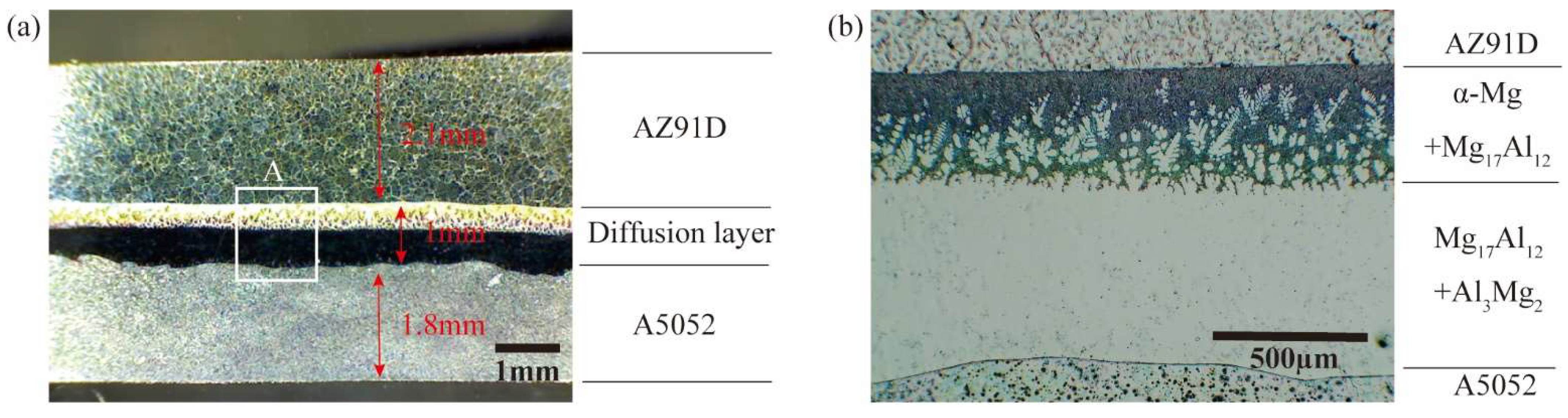
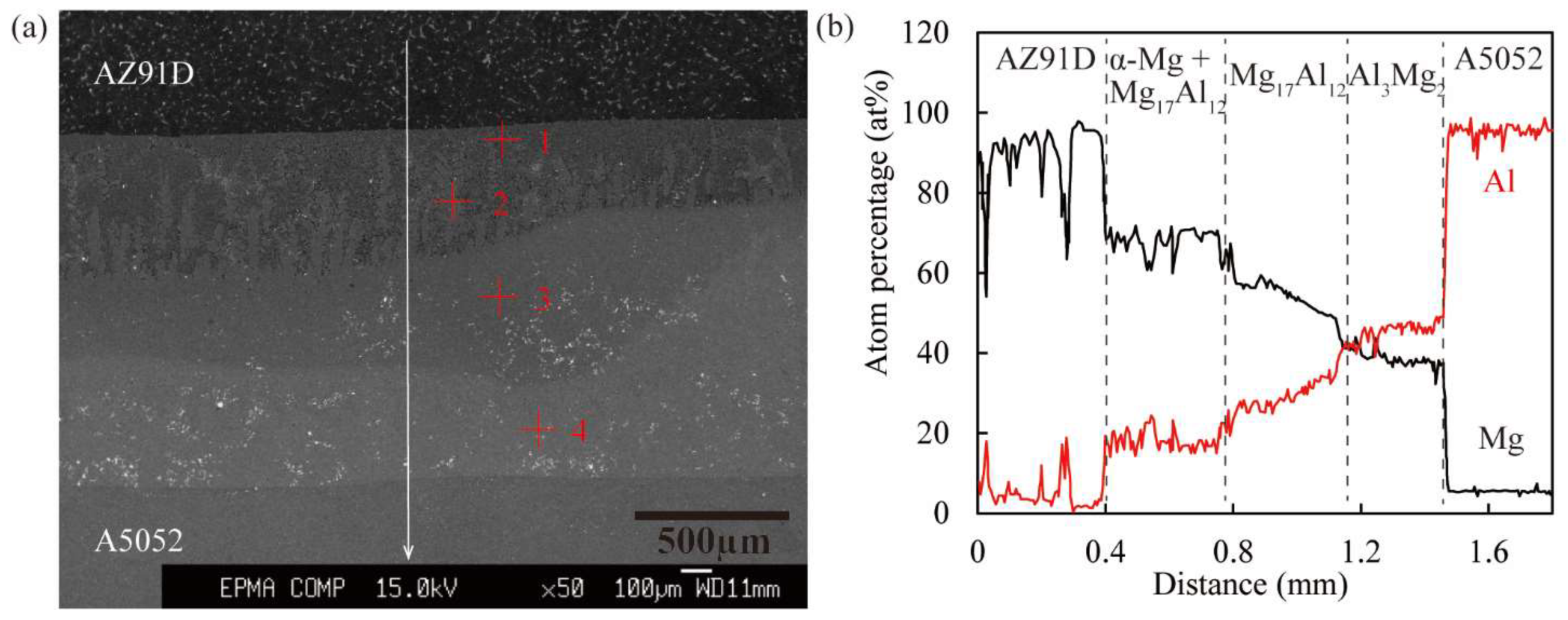
3.3. Microstructure of the Bonding Interface

Figure 9a shows the cross-section of the AZ91D/A5052 clad strips cast by the horizontal twin-roll caster. Figure 9b shows the microstructure of region A of the bonding interface in Figure 9a. We clearly observed that the bonding interface was free of voids, with two diffusion layers at the bonding interface of AZ91D and A5052. The thickness of the total diffusion layer on the bonding interface was about 1 mm, which was much greater than the thickness of the diffusion layer obtained by hot rolling [21,22]. Because the solidus temperature of A5052 was higher than the liquidus temperature of AZ91D, when the molten Mg alloy and Al alloy were combined, the temperature at the bonding interface still remained above 595 °C. This accelerated the diffusion of Mg and Al elements on the bonding surface. In addition, the thicknesses of the AZ91D layer and A5052 layer were 2.1 mm and 1.8 mm, respectively, and the cladding ratio was approximately 1:1. According to Figure 3a, the theoretical solidification thickness of A5052 at a roll speed of 9 m/min was 2.4 mm, and the thickness of the A5052 layer in the clad strip was reduced by 25%. This was because the surface of A5052 in the lower nozzle was in a semi-solidified state after the end of solidification and before bonding with the molten AZ91D [35]. When the molten AZ91D was poured onto the semi-solidified surface of A5052, the thickness of A5052 on the lower roll side was smaller than the theoretical value due to the gravity of the molten AZ91D and rolling force of the upper roll. Combining the results in Figure 10 and Table 5, it was clear that the two diffusion layers in the microstructure consisted of the α-Mg+Mg17Al12 eutectic layer near the Mg side and the Mg17Al12+Al3Mg2 compound layer near the Al side. Because the lowest magnification image of the laboratory optical microscope did not show the complete cross-section image of the clad strip, the image in Figure 9a was obtained using a normal camera under the illumination of a vertical light source. In addition, the two etching solutions used in this experiment could not etch the Mg17Al12 and Al3Mg2 layers, which were the two intermetallic compound layers that also showed a mirror effect under polishing and reflected under the irradiation of a vertical light source, causing the photographed Mg17Al12 and Al3Mg2 layers to show dark colors.
The trace element content in AZ91D and A5052 was low and most of the trace elements would solidly dissolve into α-Mg and α-Al, respectively, where the content did not change significantly. In addition, the focus of this study was on the content changes of the major elements Mg and Al, and the composition of the compounds. Figure 10 shows an SEM image of the bonding interface of the A5052/AZ91D clad strip and the EDS line scan results of the bonding interface. The SEM image and EDS line scan results indicated that the diffusion layer was divided into three layers. The chemical composition of each layer was analyzed by EDS point scanning and the results are shown in Table 5. The results showed that the layers near the AZ91D side were α-Mg and Mg17Al12, the middle was Mg17Al12, and the layer near the A5052 side was Al3Mg2. The composition of the intermetallic compounds was consistent with the results of previous studies [36,37]. Moreover, reducing the generation of intermetallic compounds has been an effective means of improving the interfacial bond strength of composite sheets [21]. For example, Ni or Zn intermediate layers were inserted between Mg alloys and Al alloys to avoid direct contact between the Mg and Al alloys, which in turn reduced the generation of Al-Mg intermetallic compounds [38,39,40]. Therefore, the future direction of this study will be to insert an Ni foil in the middle of the upper and lower nozzles to reduce the generation of intermetallic compounds and improve the bonding strength of the composite strip.

4. Conclusions

In this work, the continuous casting performance of AZ91D and A5052 was verified by single-roll casting experiments, and the experimental solidification constants of AZ91D and A5052 were obtained by empirical equations and fitted curves, with values of 62 mm/min0.5 and 34 mm/min0.5, respectively. Next, the surface temperatures of the metals during single-roll casting were measured to provide data to support the subsequent temperature change discussion of the bonding interface during double-roll composite casting. In addition, for continuous casting of a small number of metal ingots, the surface temperature variations of the casting rolls could be neglected.
Furthermore, the AZ91D/A5052 clad strips were successfully fabricated by direct cladding from molten metals using a horizontal twin-roll caster. The optimal experimental parameters were investigated by conducting tests under different experimental conditions of roll speed, pouring sequence, and solidification length. The results showed that the AZ91D/A5052 clad strip with a thickness of 4.9 mm was successfully cast at a rolling speed of 9 m/min and rolling gap of 5 mm. We found that the roll speed affected the surface state of A5052 on the lower roll side more than AZ91D on the upper roll side. In addition, the casting sequence of AZ91D/A5052 (upper nozzle metal/lower nozzle metal) made it easier to form the strip compared to A5052/AZ91D, and the intermetallic compounds produced at the bonding interface of AZ91D and A5052 could be controlled by the upper solidification length. The cross-section (Figure 9) showed that the AZ91D/A5052 strip had a cladding ratio of approximately 1:1, while three intermetallic compound layers were found at the bonding interface. Finally, the use of a horizontal twin-roll caster allowed for the direct compounding of dissimilar metals.

Author Contributions

Writing—original draft preparation, G.F.; conceptualization, T.H. and H.W.; methodology, G.F. and H.W.; investigation, G.F.; resources, H.W.; validation, G.F. and H.W.; data curation, G.F. and H.W.; writing—review and editing, G.F. and H.W.; All authors have read and agreed to the published version of the manuscript.

Funding

This research received no external funding.

Institutional Review Board Statement

Not applicable.

Informed Consent Statement

Not applicable.

Data Availability Statement

Not applicable.

Conflicts of Interest

The authors declare no conflict of interest.

References

  1. Taub, A.I.; Luo, A.A. Advanced lightweight materials and manufacturing processes for automotive applications. MRS Bull. 2015, 40, 1045–1054. [Google Scholar] [CrossRef]
  2. Hovorun, T.P.; Berladir, K.V.; Pererva, V.I.; Rudenko, S.G.; Martynov, A.I. Modern materials for automotive industry. J. Eng. Sci. 2017, 4, f8–f18. [Google Scholar] [CrossRef]
  3. Oliveira, J.P.; Ponder, K.; Brizes, E.; Abke, T.; Edwards, P.; Ramirez, A.J. Combining resistance spot welding and friction element welding for dissimilar joining of aluminum to high strength steels. J. Mater. Process. Technol. 2019, 273, 116192. [Google Scholar] [CrossRef]
  4. Yang, J.; Oliveira, J.P.; Li, Y.; Tan, C.; Gao, C.; Zhao, Y.; Yu, Z. Laser techniques for dissimilar joining of aluminum alloys to steels: A critical review. J. Mater. Process. Technol. 2022, 301, 117443. [Google Scholar] [CrossRef]
  5. Cole, G.S.; Sherman, A.M. Light weight materials for automotive applications. Mater. Charact. 1995, 35, 3–9. [Google Scholar] [CrossRef]
  6. Khorasani, M.; Ghasemi, A.; Leary, M.; Sharabian, E.; Cordova, L.; Gibson, I.; Downing, D.; Bateman, S.; Brandt, M.; Rolfe, B. The effect of absorption ratio on meltpool features in laser-based powder bed fusion of IN718. Opt. Laser Technol. 2022, 153, 108263. [Google Scholar] [CrossRef]
  7. Linares, J.; Chaves-Jacob, J.; Lopez, Q.; Sprauel, J.-M. Fatigue life optimization for 17-4Ph steel produced by selective laser melting. Rapid Prototyp. J. 2022, 28, 1182–1192. [Google Scholar] [CrossRef]
  8. Giganto, S.; Martínez-Pellitero, S.; Cuesta, E.; Zapico, P.; Barreiro, J. Proposal of design rules for improving the accuracy of selective laser melting (SLM) manufacturing using benchmarks parts. Rapid Prototyp. J. 2022, 28, 1129–1143. [Google Scholar] [CrossRef]
  9. Khan, H.M.; Waqar, S.; Koç, E. Evolution of temperature and residual stress behavior in selective laser melting of 316L stainless steel across a cooling channel. Rapid Prototyp. J. 2022, 28, 1272–1283. [Google Scholar] [CrossRef]
  10. Paul, H.; Chulist, R.; Mania, I. Structural Properties of Interfacial Layers in Tantalum to Stainless Steel Clad with Copper Interlayer Produced by Explosive Welding. Metals 2020, 10, 969. [Google Scholar] [CrossRef]
  11. Kang, M.; Zhou, L.; Deng, Y.; Luo, Y.; He, M.; Zhang, N.; Huang, Z.; Dong, L. Microstructure and Mechanical Properties of 4343/3003/6111/3003 Four-Layer Al Clad Sheets Subjected to Different Conditions. Metals 2022, 12, 777. [Google Scholar] [CrossRef]
  12. Murzin, S.P.; Palkowski, H.; Melnikov, A.A.; Blokhin, M.V. Laser Welding of Metal-Polymer-Metal Sandwich Panels. Metals 2022, 12, 256. [Google Scholar] [CrossRef]
  13. Xu, J.; Fu, J.; Li, S.; Xu, G.; Li, Y.; Wang, Z. Effect of annealing and cold rolling on interface microstructure and properties of Ti/Al/Cu clad sheet fabricated by horizontal twin-roll casting. J. Mater. Res. Technol. 2022, 16, 530–543. [Google Scholar] [CrossRef]
  14. Zhao, H.; Zhao, C.; Yang, Y.; Wang, Y.; Sheng, L.; Li, Y.; Huo, M.; Zhang, K.; Xing, L.; Zhang, G. Study on the Microstructure and Mechanical Properties of a Ti/Mg Alloy Clad Plate Produced by Explosive Welding. Metals 2022, 12, 399. [Google Scholar] [CrossRef]
  15. Song, J.; She, J.; Chen, D.; Pan, F. Latest research advances on magnesium and magnesium alloys worldwide. J. Magnes. Alloy. 2020, 8, 1–41. [Google Scholar] [CrossRef]
  16. Zhang, N.; Wang, W.; Cao, X.; Wu, J. The effect of annealing on the interface microstructure and mechanical characteristics of AZ31B/AA6061 composite plates fabricated by explosive welding. Mater. Des. 2015, 65, 1100–1109. [Google Scholar] [CrossRef]
  17. Wang, J.; Li, Y.; Liu, P.; Geng, H. Microstructure and XRD analysis in the interface zone of Mg/Al diffusion bonding. J. Mater. Process. Technol. 2008, 205, 146–150. [Google Scholar] [CrossRef]
  18. Jin, H.; Javaid, A. A new cladding technology to bond aluminium on magnesium. Mater. Sci. Technol. 2020, 36, 1037–1043. [Google Scholar] [CrossRef]
  19. Matsumoto, H.; Watanabe, S.; Hanada, S. Fabrication of pure Al/Mg–Li alloy clad plate and its mechanical properties. J. Mater. Process. Technol. 2005, 169, 9–15. [Google Scholar] [CrossRef]
  20. Kim, J.-S.; Lee, K.S.; Kwon, Y.N.; Lee, B.-J.; Chang, Y.W.; Lee, S. Improvement of interfacial bonding strength in roll-bonded Mg/Al clad sheets through annealing and secondary rolling process. Mater. Sci. Eng. A 2015, 628, 1–10. [Google Scholar] [CrossRef]
  21. Zhang, J.; Liang, W.; Li, H. Effect of thickness of interfacial intermetallic compound layers on the interfacial bond strength and the uniaxial tensile behaviour of 5052 Al/AZ31B Mg/5052 Al clad sheets. RSC Adv. 2015, 5, 104954–104959. [Google Scholar] [CrossRef]
  22. Wang, P.; Chen, Z.; Hu, C.; Li, B.; Mo, T.; Liu, Q. Effects of annealing on the interfacial structures and mechanical properties of hot roll bonded Al/Mg clad sheets. Mater. Sci. Eng. A 2020, 792, 139673. [Google Scholar] [CrossRef]
  23. Li, S.; Liu, X.; Jia, Y.; Han, J.; Wang, T. Interface Characteristics and Bonding Performance of the Corrugated Mg/Al Clad Plate. Materials 2021, 14, 4412. [Google Scholar] [CrossRef]
  24. Cao, X.; Xu, C.; Li, Y.; Cao, X.; Peng, R.; Fang, J. Effect of secondary rolling on the interfacial bonding strength and mechanical properties of Al/Mg/Al clad plates. Philos. Mag. Lett. 2022, 102, 200–208. [Google Scholar] [CrossRef]
  25. Zeng, X.; Wang, Y.; Li, X.; Li, X.; Zhao, T. Effect of inert gas-shielding on the interface and mechanical properties of Mg/Al explosive welding composite plate. J. Manuf. Process. 2019, 45, 166–175. [Google Scholar] [CrossRef]
  26. Inao, D.; Mori, A.; Tanaka, S.; Hokamoto, K. Explosive Welding of Thin Aluminum Plate onto Magnesium Alloy Plate Using a Gelatin Layer as a Pressure-Transmitting Medium. Metals 2020, 10, 106. [Google Scholar] [CrossRef]
  27. Rouzbeh, A.; Sedighi, M.; Hashemi, R. Comparison between Explosive Welding and Roll-Bonding Processes of AA1050/Mg AZ31B Bilayer Composite Sheets Considering Microstructure and Mechanical Properties. J. Mater. Eng. Perform. 2020, 29, 6322–6332. [Google Scholar] [CrossRef]
  28. Wang, Q.; Li, X.; Shi, B.; Wu, Y. Experimental and Numerical Studies on Preparation of Thin AZ31B/AA5052 Composite Plates Using Improved Explosive Welding Technique. Metals 2020, 10, 1023. [Google Scholar] [CrossRef]
  29. Atifeh, S.M.; Rouzbeh, A.; Hashemi, R.; Sedighi, M. Effect of annealing on formability and mechanical properties of AA1050/Mg-AZ31B bilayer sheets fabricated by explosive welding method. Int. J. Adv. Manuf. Technol. 2022, 118, 775–784. [Google Scholar] [CrossRef]
  30. Bae, J.H.; Prasada Rao, A.K.; Kim, K.H.; Kim, N.J. Cladding of Mg alloy with Al by twin-roll casting. Scr. Mater. 2011, 64, 836–839. [Google Scholar] [CrossRef]
  31. Park, J.; Song, H.; Kim, J.-S.; Sohn, S.S.; Lee, S. Three-Ply Al/Mg/Al Clad Sheets Fabricated by Twin-Roll Casting and Post-treatments (Homogenization, Warm Rolling, and Annealing). Metall. Mater. Trans. A 2017, 48, 57–62. [Google Scholar] [CrossRef]
  32. Haga, T.; Nakamura, R.; Kumai, S.; Watari, H. A vertical type twin roll caster for an aluminium alloy clad strip. Arch. Mater. Sci. Eng. 2013, 62, 36–44. [Google Scholar]
  33. Haga, T. Twin Roll Caster for Clad Strip. Metals 2021, 11, 776. [Google Scholar] [CrossRef]
  34. Feng, G.Y.; Watari, H.; Suzuki, M.; Haga, T.; Shimizu, T. Novel Direct Cladding of Magnesium and Aluminum Alloys Using a Horizontal Twin Roll Caster. Key Eng. Mater. 2021, 880, 17–22. [Google Scholar] [CrossRef]
  35. Haga, T. High Speed Roll Caster for Aluminum Alloy. Metals 2021, 11, 520. [Google Scholar] [CrossRef]
  36. Liu, N.; Liu, C.; Liang, C.; Zhang, Y. Influence of Ni Interlayer on Microstructure and Mechanical Properties of Mg/Al Bimetallic Castings. Metall. Mater. Trans. A 2018, 49, 3556–3564. [Google Scholar] [CrossRef]
  37. Li, G.; Jiang, W.; Guan, F.; Zhu, J.; Zhang, Z.; Fan, Z. Microstructure, mechanical properties and corrosion resistance of A356 aluminum/AZ91D magnesium bimetal prepared by a compound casting combined with a novel Ni-Cu composite interlayer. J. Mater. Process. Technol. 2021, 288, 116874. [Google Scholar] [CrossRef]
  38. Shu, J.; Yamaguchi, T.; Hara, Y. Influence of a Ni Foil Interlayer on Interface Properties of Mg-Clad Al Materials by Vacuum Roll Bonding. Mater. Trans. 2020, 61, 1020–1025. [Google Scholar] [CrossRef]
  39. Li, S.; Zheng, Z.; Chang, L.; Guo, D.; Yu, J.; Cui, M. A two-step bonding process for preparing 6061/AZ31 bimetal assisted with liquid molten zinc interlayer: The process and microstructure. J. Adhes. Sci. Technol. 2021, 1–23. [Google Scholar] [CrossRef]
  40. Dong, S.; Lin, S.; Zhu, H.; Wang, C.; Cao, Z. Effect of Ni interlayer on microstructure and mechanical properties of Al/Mg dissimilar friction stir welding joints. Sci. Technol. Weld. Join. 2022, 27, 103–113. [Google Scholar] [CrossRef]
Figure 1. Schematic showing the cladding processes of Mg/Al using a horizontal twin-roll caster (1. crucible; 2. molten metal A; 3. molten metal B; 4. upper nozzle, 5. lower nozzle; 6. upper solidification length; 7. cooling length; 8. solidification length; 9. upper roll; 10. lower roll; 11. clad strip).
Metals 12 01408 g001
Figure 2. Schematic diagram of single-roll casting.
Metals 12 01408 g002
Figure 3. (a) Relationship between the roll speed and solidification layer thickness; (b) relationship between the square root of the solidification time and the thickness of the solidification layer.
Metals 12 01408 g003
Figure 4. Surfaces of the A5052/AZ91D clad strips at a roll speed of 9 m/min. (a) Upper roll side, (b) Lower roll side.
Metals 12 01408 g004
Figure 5. Surface of the AZ91D/A5052 strips cast using the second pouring sequence with different roll speeds.
Metals 12 01408 g005
Figure 6. Schematic diagram of intermetallic compound output.
Metals 12 01408 g006
Figure 7. Casting process at different roll speeds. (a) Low speed, (b) High speed.
Metals 12 01408 g007
Figure 8. The surface of the AZ91D/A5052 clad strip with an upper solidification length of 100 mm. (a) Upper roll side, (b) Lower roll side.
Metals 12 01408 g008
Figure 9. (a) Cross-section of the AZ91D/A5052 clad strips cast by the horizontal twin-roll caster; (b) microstructure of region A of the bonding interface in (a).
Metals 12 01408 g009
Figure 10. Microstructure and EDS analysis results on the bonding interface of the Mg/Al clad strips: (a) SEM image; (b) EDS line scan result corresponding to (a).
Metals 12 01408 g010
Table 1. Chemical compositions of the AZ91D and A5052 alloys [mass%].
MaterialsMgAlSiFeCuMnZnCr
AZ91DRest90.050.0020.010.31-
A50522.5Rest0.090.140.010.01-0.25
Table 2. Experimental conditions of the single-roll casting experiments for the cast AZ91D and A5052 alloys.
MaterialsAZ91DA5052
Solidus temperature [°C]430607
Liquidus temperature [°C]595649
Pouring temperature [°C]600654
Solidification length [mm]50
Cooling length [mm]50
Roll speed [m/min]6–36
Table 3. Casting conditions for the Mg/Al clad strips.
MaterialsAZ91DA5052
Pouring temperature [°C]600654
Pouring sequence [upper nozzle/lower nozzle]A5052/AZ91D, AZ91D/A5052
Upper solidification length [mm]50, 100
Solidification length [mm]50
Cooling length [mm]50
Roll gap [mm]5
Roll speed [m/min]6–12
Roll surface temperature [°C]22
Table 4. Experimental results under different roll speeds and pouring sequences.
Pouring Sequence
[Upper Nozzle/Lower Nozzle]
Roll Speed [m/min]
6912
A5052/AZ91D×××
AZ91D/A5052××
×: bad, ∆: not good.
Table 5. Results of EDS point scan analysis at different positions of the interface corresponding to Figure 10a.
PointMgAlPossible Phase
190.159.49α-Mg
266.7033.30α-Mg+Mg17Al12
356.8643.14Mg17Al12
443.3256.68Al3Mg2
Publisher’s Note: MDPI stays neutral with regard to jurisdictional claims in published maps and institutional affiliations.

