Article

Quasi-Static Three-Point Bending Behavior of Aluminum Foam Sandwich with CFRP Face-Sheets

School of Metallurgy, Northeastern University, Shenyang 110891, China
*
Author to whom correspondence should be addressed.
Metals 2022, 12(8), 1393; https://doi.org/10.3390/met12081393
Submission received: 30 July 2022 / Revised: 9 August 2022 / Accepted: 19 August 2022 / Published: 22 August 2022
(This article belongs to the Special Issue Synthesis and Applications of Metallic Foams)

Abstract

:
Aluminum foam sandwich panels are excellent structure–function integrated materials. With high specific strength, cushioning energy absorption and sound absorption of aluminum foam material, they overcome the disadvantage of the low strength of single aluminum foam materials. In this paper, the response of aluminum sandwich panels comprising aluminum foam cores and carbon fiber reinforced plastic (CFRP) face-sheets was investigated under quasi-static three-point bending, and the effect of core thickness as well as core density on flexural loads and deformation modes was studied. The experimental results show that increasing the thickness and the density of the core materials can increase the flexural load and bending stiffness in the bending process. The aluminum foam sandwich panels mainly include the following deformation modes in the three-point bending process: indentation, core shear, face-sheet fracture and debonding.

1. Introduction

Sandwich structures with porous materials are widely used in a variety of applications and have been extensively studied due to their unique properties, such as high stiffness, high strength, light weight, vibration reduction and high dumping [1,2,3,4,5,6,7,8]. Most of the core materials of sandwich structures are based on polymeric foams such as PVC, PUR and PEI, as well as aluminum honeycomb. With the development of porous metal, aluminum foam has gradually become a new choice for the core material [9,10,11]. It has a series of excellent physical characteristics such as low specific weight, high specific stiffness and strength, energy absorption, blast resistance and noise attenuation [12,13,14,15]. However, it also has poor mechanical properties, especially under tension [16]. As a new type of structural–functional material and a kind of composite material, the aluminum foam sandwich structure consists of an aluminum foam core and two stiff pieces of metal or nonmetal face-sheets, which makes it have the advantages of aluminum foam, and overcomes the shortcomings of poor mechanical properties of single aluminum foam [17]. Thus, it has great potential applications in many fields, such as automobile manufacturing, architecture and aerospace [9,18,19,20].
In general structural applications, bending response is vital for sandwich structures. The main methods to change the bending performance of sandwich structures include changing the geometric parameters of the sandwich structures, changing the mode of interface bonding and using different materials of face-sheets and foam cores. McCormack et al. [21] found four different failure modes of sandwich structures: surface yield, surface wrinkling, core yield and indentation. Analytical models were established to predict the initial failure loads, and failure mode maps were constructed with geometric parameters as variables. Steeves et al. [22,23,24] also conducted a similar study, and on this basis, the size of the sandwich structure was optimized, and further research was carried out in combination with finite element analysis. The size effect of foam core is also very important for bending response [25]. The discrepancy between the measured and calculated failure load increase to over 20% if the size effect in the core shear was neglected. The above research mainly reveals the influence of geometric parameters on the bending response of sandwich structures in theory. The interface bonding mode of aluminum foam sandwich panels is mostly adhesive bonding, and their bending performance can also be effectively improved by improving or changing the interface bonding mode. For the aluminum foam sandwich structure with non-metallic material face-sheets, short aramid fibers were successfully used between carbon fiber/epoxy composites and aluminum foam to enhance interfacial toughness [26,27,28]. Adding aramid fiber increases the peak load by 38% and energy absorption by 80%, and the aramid fiber occupies less than 1% of the total weight of the sandwich structure. For the aluminum foam sandwich structure with metal face-sheets, the bonding force can be improved by forming metallurgical bonding between the interfaces [29,30]. Changing the material of the sandwich panel is also one of the important methods to change its bending properties. Current research mainly focuses on changing the materials used for face-sheets. Kabir et al. [31] investigated the response of aluminum sandwich panels comprising thin foam cores and thin face sheets of low and high strength under a three-point bending load. The effects of skin strength, bending span and core thickness on failure modes and loads were also investigated. Aluminum foam sandwich panels usually use metal materials as face-sheets, especially aluminum alloys. In order to further improve the performance of the sandwich structure, some studies used non-metallic face-sheets materials, such as alumina and glass fiber reinforced plastic [32,33], especially carbon fiber reinforced plastic [27,34,35,36,37], as face-sheets materials. With the further improvement of lightweight requirements, carbon fiber reinforced plastic (CFRP) materials with high strength and low density are gradually used as face-sheets material.
The above literature carried out a great number of studies on the flexural properties of aluminum foam sandwiches. Existing analyses mainly change the performance of sandwich structure by changing geometric parameters, interface bonding modes and face-sheet materials. There are few studies on using different aluminum foams as the core material. Most of the research uses commercial aluminum foam as the core material. The density and cell structure of the commercialized aluminum foam is relatively single. However, the effect of the foam core density on the flexural properties of the sandwich structure is also crucial. In order to investigate the effect of aluminum foam density on the properties of the sandwich structure, three kinds of aluminum foams with different densities were prepared by the melt foaming method in this paper. In addition, compared with the existing research, the aluminum foam used in this experiment has a more uniform structure and better mechanical properties. The main purpose of this paper is to experimentally investigate the effect of core thickness and density on loading capacity and deformation modes of the aluminum foam sandwich with CFRP face-sheets under quasi-static three-point bending.

2. Experimental Investigation

2.1. Materials and Specimens

Three kinds of aluminum foam materials with different densities (0.37 g/cm3, 0.57 g/cm3 and 0.75 g/cm3) prepared by the melt foaming method were used as core materials in sandwich structures [38]. Aluminum foam materials were prepared using four raw materials: primary aluminum (purity 99.7%), industrial calcium (purity 99.5%), titanium hydride powder (mean diameter: 22 μm, purity 99.4%, pre-treated at 400 °C for 30 min) and argon. The primary aluminum was melted at 720 °C, and 3 wt.% calcium was added to increase the viscosity of the molten aluminum. Then, the temperature was lowered to 685 °C and 1.2 wt.% titanium hydride powder was added to the melt with a revolution speed of 900 rpm for 180 s. Finally, according to the required density of the foam, a certain pressure of argon was introduced, and the temperature was maintained for a certain period of time.
The CFRP face-sheets were made of T700 woven carbon fabric with 200 GSM densities, and each yarn had approximately 12,000 fibers. The thickness of the CFRP face-sheets was 2.0 mm, and the density of this material was 1.41 g/cm3.
Before preparing sandwich panels, aluminum foam materials and face-sheets were cut to the required dimensions and cleaned with alcohol. To provide better adhesion, surfaces of aluminum foam and face-sheets were abraded with sandpaper. Then, they were washed with water and dried at 80 °C in the drying oven. After preparing aluminum foam cores and face-sheets, epoxy resin was mixed with hardener in the proportion of 3:1 as the adhesive of aluminum foam sandwich structures, and the aluminum foam and face-sheets were glued together with the adhesive. According to the parameters of epoxy resin, the glued sandwich structures were heated to a temperature of 40 °C in a drying oven for six hours under a certain pressure to cure the epoxy resin completely.

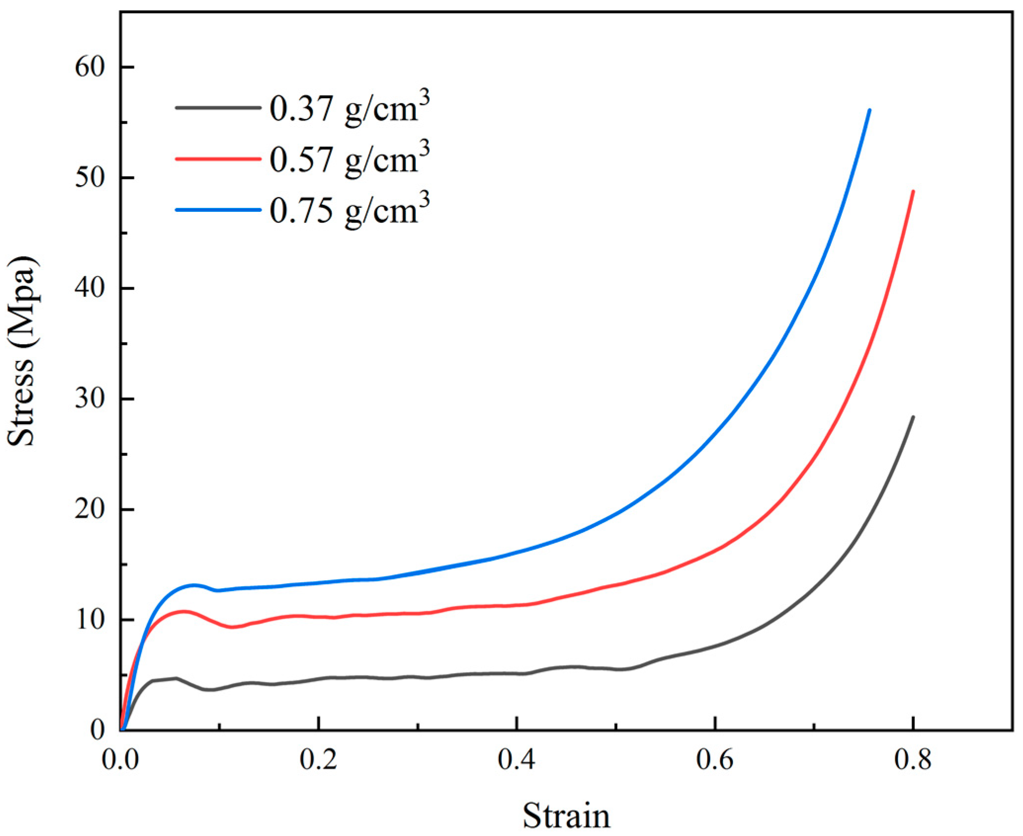
2.2. Quasi-Static Compression Test of Aluminum Foam Materials

Quasi-static compression tests of the aluminum foams were conducted at room temperature using the universal testing machine with a 50 kN load cell. The compression rate during the test was 2 mm/min. Aluminum foam materials were cut into cubes with a side length of 30 mm for testing.

2.3. Quasi-Static Three-Point Bending Test of Aluminum Foam Sandwiches

Quasi-static three-point bending tests of the aluminum foam sandwich panels were conducted at room temperature, using the universal testing machine with a 50 kN load cell. The schematic diagram of the three-point bending test is shown in Figure 1. Referring to the existing literature and in combination with the requirements of this study, the following experimental parameters were determined [27,29,37]. The three-point bending tests were carried out with a span length (l) of 80 mm, and the loading roller and supporting rollers (a) of a simply supported beam with a 10 mm diameter were used. The length of the specimens was 150 mm and the width (b) of specimens was 30 mm. Table 1 summarize the dimensions of the specimens used in the experimental work. During the test, the aluminum foam sandwich panels were loaded by the loading roller at mid-span with a rate of 2 mm/min. Through the three-point bending test, flexural loads and indenter displacements were recorded by the software connected with the universal testing machine, and flexural load–displacement curves were obtained. Photographs were taken using a digital camera to record the deformation of the aluminum foam sandwich panels. Each group of experiments was repeated at least three times.

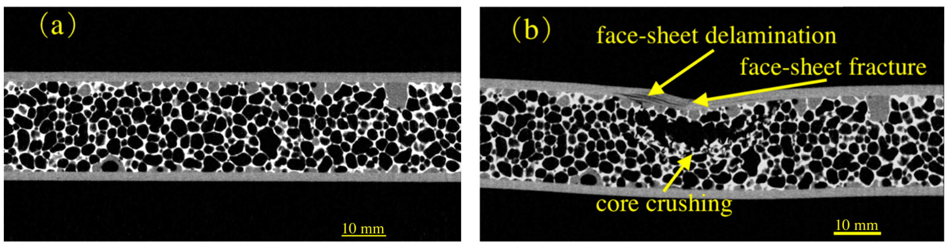
2.4. X-ray Tomography

The specimens were scanned using a microfocus X-ray CT system (Dandong Aolong ray Instrument Group Co., Ltd., Dandong, Liaoning, China) after deformation. The scanned images of specimens were obtained by rotating the specimens 360° in steps of 0.5°. Compared with optical photos, the observation of failure modes of specimens by tomography was clearer in some cases, especially the failure modes of CFRP face-sheets. The back-projection reconstruction algorithm was used to slice the radioscopic projections by scanning. The reconstructed 2D slices were imported into VG Studio Max to build a 3D model, and a section in any direction can be acquired.

3. Results

3.1. Quasi-Static Compression Properties of Aluminum Foams

The compression nominal stress–strain curves of three different kinds of aluminum foams with different densities are shown in Figure 2. The stress–strain curves can be divided into three stages: (I) linear elastic stage; (II) plateau stage; (III) densification stage. The compressive strengths of the three kinds of aluminum foams are 4.7 MPa, 10.7 MPa and 13.1 MPa, respectively. According to the experiment, it can be seen that the compressive strength and plateau stress goes up with the increase of the density of the foam. In addition, the densification stage of the curve advances as the density of the aluminum foam increases.

3.2. Load–Displacement Curves of Quasi-Static Three-Point Bending Behaviors of Aluminum Foam Sandwich Panels

In this chapter, the flexural load–displacement curves of the quasi-static three-point bending behavior of aluminum foam sandwich panels with different core thicknesses and core densities were investigated.
The measured flexural load–displacement curves of specimens with different core materials are shown in Figure 3. Figure 3a,b show the effects of thickness (thickness = 10, 20, 30 mm) and density (density = 0.37, 0.57, 0.75 g/cm3) of core material, respectively. It can be seen from the figure that the flexural load of the sandwich panel can be improved using core material with a thicker thickness or higher density. In addition, the slope in the early stage of the curves increases with the increase of core thickness and core density, which indicates greater stiffness of the sandwich panels. It can also be noted from the figure that the curves of #10-0.37 and #20-0.75 finally show a linear decline, which indicates that the bending process of the specimens ends with a complete loss of bearing capacity [27].
There are some similarities and differences in the trend of curves of specimens with different core materials. Figure 4 show the analysis of the curve of #20-0.37 appearing in both groups of curves. The curve demonstrated the following four stages: (I) linear elastic deformation stage; (II) nonlinear growth stage; (III) instability stage; (IV) plateau/densification stage. In the first stage, the flexural load increases linearly with the increase of displacement. After the linear stage, the curve grows nonlinearly and reaches its peak load (Pcr) 4340 N, with displacement reaching 2.72 mm. After reaching the peak value, the curve enters the instability stage and the flexural load decreases to a certain extent. In the fourth stage, the flexural load–displacement curve enters the plateau stage. The average load Pm of the plateau stage is 3096 N, 1244 N lower than the peak load Pcr.
Figure 5 show the analysis of curves of #10-0.37 and #30-0.37. The curve of #30-0.37 is similar to that of #20-0.37, which can be divided into four stages. The difference is that the curve of #30-0.37 shows an upward trend rather than a platform after experiencing the same first three stages as #20-0.37. There are two differences between the curves of #10-0.37 and #20-0.37. One is that the curve of #10-0.37 finally shows a vertical decline as mentioned earlier, and the other is that the curve of #10-0.37 shows a short platform after reaching the peak load (displacement = 2.86 mm), rather than entering the instability stage immediately. When displacement reaches 4.47 mm, the curve enters the instability stage, showing a downward trend. It can also be seen from Figure 3a that after the instability stage, the increase in the thickness of core material from 10 mm to 20 mm does not increase significantly in the flexural load. When the core material thickness reaches 30 mm, the load increases significantly and continues to rise after the instability stage. The reason for the above situation is that when the thicker aluminum foam is used as the core material, the contribution of the core material to the bending of the sandwich structure becomes greater.
According to Figure 3b, for the specimens with different densities of core materials, the curves of #20-0.57 and #20-0.75 have the same three stages, namely, the linear elastic stage, nonlinear stage and instability stage, as that of #20-0.37. After the instability stage, the curves of the two specimens with higher core material density are different from that of #20-0.37. As shown in Figure 6, the curves of #20-0.57 and #20-0.75 showed an upward trend at first, and then the flexural load fluctuated from falling to rising when the displacement of the two curves reached 13.88 mm and 15.76 mm, respectively. The curve of #20-0.75 finally showed a vertical decline.
The bending stiffness of aluminum foam sandwich panels, R (N·m2), was calculated using the following relationship [37].
R = P c r l 3 48 S cr ,
where Pcr (N) is peak load, l (mm) is the span length and Scr (mm) is the displacement at a particular peak load. The bending stiffness (R) of all five specimens used in the experiment is shown in Table 2. According to the calculation, the bending stiffness of #30-0.37 is increased by 64% compared with #20-0.37, which is much higher than the 26% of #20-0.37 compared with #10-0.37. The increase of core density is obvious for the improvement of bending stiffness, and the two increases (0.37 g/cm3–0.57 cm3, 0.57 cm3–0.75 cm3) in density increase the bending stiffness by 74% and 54%, respectively.
The weight of core materials used in #30-0.37 and #20-0.57 are very close; thus, the performance comparison between them is very noteworthy. It can be seen from Table 2 that the peak load and bending stiffness of #20-0.57 are slightly higher than that of #30-0.37, and the difference is within 10%. This indicated that when the weight of the core material is determined, the core material with higher density has better performance than that with greater thickness. This is because the strength of aluminum foam is positively correlated with the index of density, which is generally between 1.5–2.0 [38].

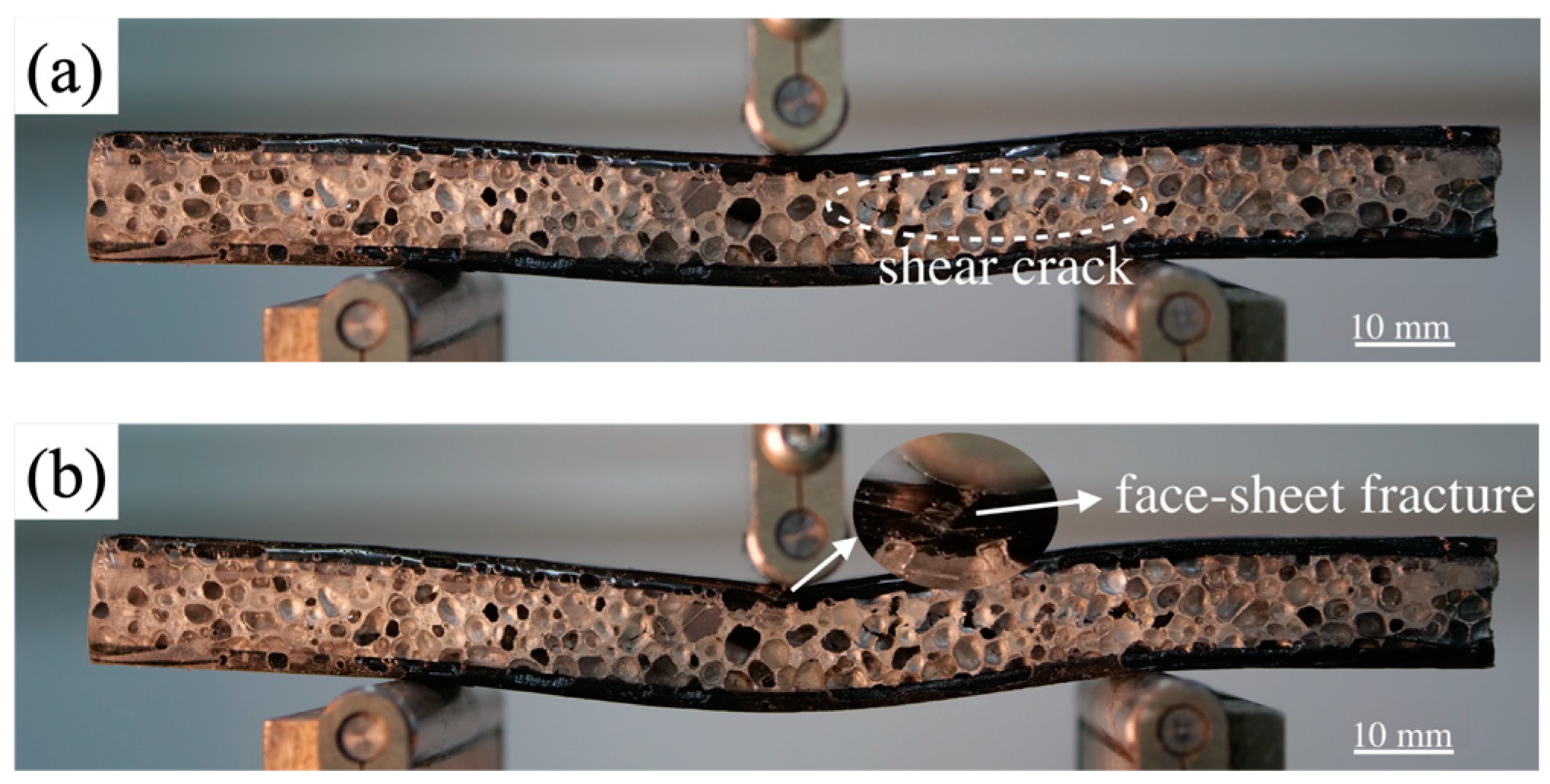
3.3. Deformation of Quasi-Static Three-Point Bending Behaviors of Aluminum Foam Sandwich Panels

In this chapter, the deformation process of quasi-static three-point bending of aluminum foam sandwich panels is investigated, and the flexural load–displacement curves in the previous section are further analyzed in combination with the deformation modes. The deformation modes of aluminum foam sandwiches during three-point bending mainly include indentation, core shear, upper face-sheet fracture and debonding [21,23,25,34]. Figure 7 show the deformation modes of all specimens used in this experiment.
It can be seen from Figure 7 that the other four specimens have an obvious indentation at the loading point except #10-0.37. Compared with #10-0.37, the area directly below the loading point of other specimens was seriously invaded by the indenter, and the core material collapsed. Among them, #20-0.37 and #30-0.37 only showed indentation and did not have other obvious failure modes. Taking #20-0.37 as an example, Figure 8 show the generation of indentation. The four photos in the figure correspond to the four stages of the flexural load–displacement curve of #20-0.37 (Figure 4), respectively. In the linear elastic deformation stage, as Figure 8a show, the aluminum foam sandwich shows slight deformation, and the deformation area is located between two supports. Subsequently, the specimen gradually began to undergo plastic deformation and cracks appeared in some bubbles (as shown in Figure 8b), making the curve enter the stage of nonlinear growth. When the flexural load reached the peak value, the aluminum foam in the area below the indenter began to collapse, resulting in the upper face-sheet beginning show indentations under the loading of the indenter (as shown in Figure 8c). In this deformation process, the curve enters the instability stage. It can be seen from Figure 8d that the aluminum foam under the indenter was severely crushed and densified, and the upper face-sheet was seriously invaded by the indenter. This process makes the curve enter the plateau stage.
Figure 9 show the comparison of the tomography cross-sectional photos of #20-0.37 before and after the three-point bending test. It can be seen more clearly that the foam core underneath the loading point is obviously damaged. In addition, compared with ordinary optical photos, the changes in CFRP face-sheets after the bending process can be observed more clearly by tomography photos. As is shown in Figure 9b, the upper face-sheet is obviously damaged. The CFRP face-sheet composed of a multi-layer structure showed delamination, and some layers were slightly fractured below the loading point. The damage to the upper face-sheet was similar to that reported in the literature [35]. The failure of CFRP material is usually brittle, resulting in the instability stage and densification stage of the curve being less smooth compared to the rising stage and obvious small-scale fluctuations exist.
Figure 7a–c show the deformation mode photos of the three-point bending test of the specimens with different core thicknesses (thickness = 10, 20, 30 mm). The corresponding curves are shown in Figure 3a. The deformation modes of #20-0.37 and #30-0.37 are the same, which are indentations below the loading point. The deformation mode of #10-0.37 is different. It can be seen from the photo that the aluminum foam core has an obvious shear failure, extending from the middle of the specimen to the right edge. Core shear divides the right half of the specimen into upper and lower parts, which leads to the complete loss of bearing capacity of the sandwich structure, and the corresponding curve decreases linearly. Furthermore, the upper face-sheet of the specimen presents a V-shape, indicating that the upper panel has brittle damage under load. Figure 10a,b show the photos when the displacement of the curve of #10-0.37 reaches 2.86 mm and 4.47 mm, respectively. When the displacement reaches 2.86 mm, the shear crack on the core material is formed, and the bending load reaches the peak (as Figure 5 shown). The curve subsequently enters a brief plateau stage. When the displacement reaches 4.47 mm, the upper face-sheet brakes under the indenter, causing the curve to enter the stage of instability.
Figure 11 show the deformation modes of #10-0.37 and #30-0.37 by X-ray Tomography. The damage to the face-sheets of #10-0.37 can be seen more intuitively through the tomography. It was found that the upper face-sheet is an obvious fracture. For the sandwich structure with a thicker aluminum foam core, the continuous crushing of the core during bending plays a good role in energy absorption. When the core material is thin, it plays a weak role in the bending process; thus, the upper face-sheet presents an obvious fracture phenomenon.
Figure 7b,d,e show the photos of deformation modes of the three-point bending test of specimens with different core density (density = 0.37, 0.57, 0.75 g/cm3). The core thickness of the three specimens is 20 mm. As mentioned earlier, an obvious indentation at the loading point can be observed in all three specimens. This proves that when the thickness of CFRP face-sheets is 2 mm, and the thickness of aluminum foam core is 20 mm, the phenomenon of indentation at the loading point in the bending process of sandwich structure is not affected by the density of the core. The generation of indentation causes the core material below the loading point to be severely compressed, and increasing the density of aluminum foam makes the densification advance in the compression process, which leads to the curves of #20-0.57 and #20-0.75 to rise after the instability stage (shown in Figure 6). When the core density increases to 0.57 g/cm3 and above, the phenomenon of core shear appears in the deformation process. Similar results were obtained in the literature for increasing the flexural load by increasing the face-sheets thickness [35].
As shown in Figure 7, the core material of #20-0.57 and #20-0.75 showed shear failure, which occurred in the area between the loading point and right side support roller. In addition, it can be seen that the core materials of both specimens are partially debonded from the lower panel on the left side of the right support. Local debonding is caused by the relative sliding of the core material along the shear crack under the action of flexural load. Taking #20-0.57 as an example, the photo was taken when the specimen just showed local debonding (shown in Figure 12). At this time, the displacement corresponding to the curve in Figure 6 is 13.88 mm. With the increasing local debonding range and the interaction between core materials, an obvious fluctuation occurred in the later stage of the curve (shown in Figure 6).
It can be clearly observed by tomography (Figure 13) that the aluminum foam core of #20-0.57 and #20-0.75 has obvious shear failure and debonding. There are two debonding phenomena in #20-0.75. The left one is complete debonding, and the right one is local debonding. The former leads to the complete loss of bearing capacity of the sandwich structure, resulting in a linear decline in its flexural load–displacement curve (Figure 3b). Since the load has not been removed during the shooting of Figure 7e, there is no obvious debonding phenomenon in ordinary optical photos. The mechanism of debonding failure is that the relative force between the lower panel and the core material is greater than the bonding force between them.

4. Conclusions

This study investigated the response of aluminum foam sandwich panels with CFRP face-sheets under quasi-static three-point bending loading conditions. Three kinds of aluminum foam materials with different densities were prepared by the melt foaming method as core materials. The effect of core thickness and core density was elucidated. Increasing the thickness and density of the core materials can increase the flexural load and bending stiffness in the bending process. When the weight of the core material was determined, the core material with higher density had a higher peak load and bending stiffness than that with greater thickness. Four main deformation or failure modes of sandwich panels were identified in this study, namely, indentation, core shear, upper face-sheet fracture and debonding. When the thickness of the core material was greater than or equal to 20 mm, all sandwich panels appeared as obvious indentations at the loading point. The complete fracture of the upper face-sheet occurred when the core material was too thin (10 mm). Core shear occurs when the density of the core based on a pure aluminum matrix is greater than or equal to 0.57 g/cm3, or the thickness of the core is excessively thin (10 mm). When the density of the core reaches 0.75 g/cm3, the excessive load leads to the debonding failure of the aluminum foam sandwich panels.

Author Contributions

Conceptualization, Z.C.; writing—original draft preparation, methodology, validation, formal analysis and investigation, X.W. and Z.C.; software and data curation, X.W.; writing—review and editing, Z.C. and G.F. All authors have read and agreed to the published version of the manuscript.

Funding

This work was financially supported by the State Administration of Science, Technology and Industry for National Defense Project JCKY2018110C051.

Institutional Review Board Statement

Not applicable.

Informed Consent Statement

Not applicable.

Data Availability Statement

Not applicable.

Acknowledgments

The authors acknowledge the State Administration of Science, Technology and Industry for National Defense for financial support.

Conflicts of Interest

The authors declare no conflict of interest.

References

  1. Zhao, Y.; Yang, Z.; Yu, T.; Xin, D. Mechanical properties and energy absorption capabilities of aluminium foam sandwich structure subjected to low-velocity impact. Constr. Build. Mater. 2021, 273, 121996. [Google Scholar] [CrossRef]
  2. Cai, S.; Liu, J.; Zhang, P.; Li, C.; Cheng, Y.; Chen, C. Experimental study on failure mechanisms of sandwich panels with multi-layered aluminum foam/UHMWPE laminate core under combined blast and fragments loading. Thin Walled Struct. 2021, 159, 107227. [Google Scholar] [CrossRef]
  3. Huo, X.; Sun, G.; Zhang, H.; Lv, X.; Li, Q. Experimental study on low-velocity impact responses and residual properties of composite sandwiches with metallic foam core. Compos. Struct. 2019, 223, 110835. [Google Scholar] [CrossRef]
  4. Sun, G.; Wang, E.; Wang, H.; Xiao, Z.; Li, Q. Low-velocity impact behaviour of sandwich panels with homogeneous and stepwise graded foam cores. Mater. Des. 2018, 160, 1117–1136. [Google Scholar] [CrossRef]
  5. Crupi, V.; Kara, E.; Epasto, G.; Guglielmino, E.; Aykul, H. Prediction model for the impact response of glass fibre reinforced aluminium foam sandwiches. Int. J. Impact Eng. 2015, 77, 97–107. [Google Scholar] [CrossRef]
  6. Safaei, B. The effect of embedding a porous core on the free vibration behavior of laminated composite plates. Steel Compos. Struct. 2020, 35, 659–670. [Google Scholar] [CrossRef]
  7. Safaei, B. Frequency-dependent damped vibrations of multifunctional foam plates sandwiched and integrated by composite faces. Eur. Phys. J. Plus 2021, 136, 646. [Google Scholar] [CrossRef]
  8. Ghanati, P.; Safaei, B. Elastic buckling analysis of polygonal thin sheets under compression. Indian J. Phys. 2018, 93, 47–52. [Google Scholar] [CrossRef]
  9. Tang, E.; Zhang, X.; Han, Y. Experimental research on damage characteristics of CFRP/aluminum foam sandwich structure subjected to high velocity impact. J. Mater. Res. Technol. 2019, 8, 4620–4630. [Google Scholar] [CrossRef]
  10. Reyes Villanueva, G.; Cantwell, W.J. The high velocity impact response of composite and FML-reinforced sandwich structures. Compos. Sci. Technol. 2004, 64, 35–54. [Google Scholar] [CrossRef]
  11. Yu, J.L.; Wang, X.; Wei, Z.G.; Wang, E.H. Deformation and failure mechanism of dynamically loaded sandwich beams with aluminum-foam core. Int. J. Impact Eng. 2003, 28, 331–347. [Google Scholar] [CrossRef]
  12. Ren, C.-X.; Hu, Z.-F.; Yao, C.; Mo, F. Experimental study on the quasi-static compression behavior of multilayer aluminum foam sandwich structure. J. Alloy. Compd. 2019, 810, 151860. [Google Scholar] [CrossRef]
  13. Islam, M.A.; Brown, A.D.; Hazell, P.J.; Kader, M.A.; Escobedo, J.P.; Saadatfar, M.; Xu, S.; Ruan, D.; Turner, M. Mechanical response and dynamic deformation mechanisms of closed-cell aluminium alloy foams under dynamic loading. Int. J. Impact Eng. 2018, 114, 111–122. [Google Scholar] [CrossRef]
  14. Birla, S.; Mondal, D.P.; Das, S.; Khare, A.; Singh, J.P. Effect of cenosphere particle size and relative density on the compressive deformation behavior of aluminum-cenosphere hybrid foam. Mater. Des. 2017, 117, 168–177. [Google Scholar] [CrossRef]
  15. Liu, J.; Qu, Q.; Liu, Y.; Li, R.; Liu, B. Compressive properties of Al-Si-SiC composite foams at elevated temperatures. J. Alloy. Compd. 2016, 676, 239–244. [Google Scholar] [CrossRef]
  16. Banhart, J.; Seeliger, H.W. Aluminium Foam Sandwich Panels: Manufacture, Metallurgy and Applications. Adv. Eng. Mater. 2008, 10, 793–802. [Google Scholar] [CrossRef]
  17. Yan, C.; Song, X.; Jing, C.; Feng, S. Effects of epoxy resin liquidity on the mechanical properties of aluminum foam sandwich. J. Adhes. Sci. Technol. 2017, 32, 673–691. [Google Scholar] [CrossRef]
  18. Liang, X.; Luo, H.; Mu, Y.; Wu, L.; Lin, H. Experimental study on stress attenuation in aluminum foam core sandwich panels in high-velocity impact. Mater. Lett. 2017, 203, 100–102. [Google Scholar] [CrossRef]
  19. Cheng, S.L.; Zhao, X.Y.; Xin, Y.J.; Du, S.Y.; Li, H.J. Quasi-static localized indentation tests on integrated sandwich panel of aluminum foam and epoxy resin. Compos. Struct. 2015, 129, 157–164. [Google Scholar] [CrossRef]
  20. Vogel, J.; Keller, J.; Sviridov, A.; Feige, H.J.; Kreyssig, K.; Auersperg, J.; Plass, P.; Walter, H. Characterisation of Strength Behaviour of Aluminium Foam Sandwiches Under Static Load. Strain 2011, 47, e234–e242. [Google Scholar] [CrossRef]
  21. McCormack, T.M.; Miller, R.; Kesler, O.; Gibson, L.J. Failure of sandwich beams with metallic foam cores. Int. J. Solids Struct. 2001, 38, 4901–4920. [Google Scholar] [CrossRef]
  22. Steeves, C.A.; Fleck, N.A. Material selection in sandwich beam construction. Scr. Mater. 2004, 50, 1335–1339. [Google Scholar] [CrossRef]
  23. Steeves, C.A.; Fleck, N.A. Collapse mechanisms of sandwich beams with composite faces and a foam core, loaded in three-point bending. Part I: Analytical models and minimum weight design. Int. J. Mech. Sci. 2004, 46, 561–583. [Google Scholar] [CrossRef]
  24. Steeves, C.A.; Fleck, N.A. Collapse mechanisms of sandwich beams with composite faces and a foam core, loaded in three-point bending. Part II: Experimental investigation and numerical modelling. Int. J. Mech. Sci. 2004, 46, 585–608. [Google Scholar] [CrossRef]
  25. Kesler, O.; Gibson, L.J. Size effects in metallic foam core sandwich beams. Mater. Sci. Eng. A 2002, 326, 228–234. [Google Scholar] [CrossRef]
  26. Sun, Z.; Shi, S.; Hu, X.; Chen, H.; Wong, Z. Adhesive joints between carbon fiber and aluminum foam reinforced by surface-treated aramid fibers. Polym. Compos. 2015, 36, 192–197. [Google Scholar] [CrossRef]
  27. Sun, Z.; Hu, X.; Sun, S.; Chen, H. Energy-absorption enhancement in carbon-fiber aluminum-foam sandwich structures from short aramid-fiber interfacial reinforcement. Compos. Sci. Technol. 2013, 77, 14–21. [Google Scholar] [CrossRef]
  28. Sun, Z.; Jeyaraman, J.; Sun, S.; Hu, X.; Chen, H. Carbon-fiber aluminum-foam sandwich with short aramid-fiber interfacial toughening. Compos. Part A Appl. Sci. Manuf. 2012, 43, 2059–2064. [Google Scholar] [CrossRef]
  29. Zu, G.; Song, B.; Zhong, Z.; Li, X.; Mu, Y.; Yao, G. Static three-point bending behavior of aluminum foam sandwich. J. Alloy. Compd. 2012, 540, 275–278. [Google Scholar] [CrossRef]
  30. Linul, E.; Marsavina, L.; Kováčik, J. Collapse mechanisms of metal foam matrix composites under static and dynamic loading conditions. Mater. Sci. Eng. A 2017, 690, 214–224. [Google Scholar] [CrossRef]
  31. Kabir, K.; Vodenitcharova, T.; Hoffman, M. Response of aluminium foam-cored sandwich panels to bending load. Compos. Part B Eng. 2014, 64, 24–32. [Google Scholar] [CrossRef]
  32. Mohan, K.; Hon, Y.T.; Idapalapati, S.; Seow, H.P. Failure of sandwich beams consisting of alumina face sheet and aluminum foam core in bending. Mater. Sci. Eng. A 2005, 409, 292–301. [Google Scholar] [CrossRef]
  33. Styles, M.; Compston, P.; Kalyanasundaram, S. The effect of core thickness on the flexural behaviour of aluminium foam sandwich structures. Compos. Struct. 2007, 80, 532–538. [Google Scholar] [CrossRef]
  34. Mohan, K.; Yip, T.H.; Sridhar, I.; Seow, H.P. Design of Hybrid Sandwich Panel with Aluminum Foam Core and Carbon Fiber Reinforced Plastic Face Sheets under Three-Point Bending. Solid State Phenom. 2006, 111, 63–66. [Google Scholar] [CrossRef]
  35. Zhang, W.; Qin, Q.; Li, J.; Li, K.; Poh, L.H.; Li, Y.; Zhang, J.; Xie, S.; Chen, H.; Zhao, J. Deformation and failure of hybrid composite sandwich beams with a metal foam core under quasi-static load and low-velocity impact. Compos. Struct. 2020, 242, 112175. [Google Scholar] [CrossRef]
  36. Rupp, P.; Elsner, P.; Weidenmann, K.A. Failure mode maps for four-point-bending of hybrid sandwich structures with carbon fiber reinforced plastic face sheets and aluminum foam cores manufactured by a polyurethane spraying process. J. Sandw. Struct. Mater. 2017, 21, 2654–2679. [Google Scholar] [CrossRef]
  37. Pandey, A.; Muchhala, D.; Kumar, R.; Sriram, S.; Venkat, A.N.C.; Mondal, D.P. Flexural deformation behavior of carbon fiber reinforced aluminium hybrid foam sandwich structure. Compos. Part B Eng. 2020, 183, 107729. [Google Scholar] [CrossRef]
  38. Yu, Y.; Cao, Z.; Tu, G.; Mu, Y. Energy Absorption of Different Cell Structures for Closed-Cell Foam-Filled Tubes Subject to Uniaxial Compression. Metals 2020, 10, 1579. [Google Scholar] [CrossRef]
Figure 1. Schematic diagram of three-point bending test.
Metals 12 01393 g001
Figure 2. Compressive stress–strain curves of aluminum foams.
Metals 12 01393 g002
Figure 3. Flexural load–displacement curves of three-point bending test of aluminum foam sandwich panels: (a) different core thickness; (b) different core density.
Metals 12 01393 g003
Figure 4. Analysis of flexural load–displacement curve of #20-0.37.
Metals 12 01393 g004
Figure 5. Analysis of flexural load–displacement curves of #10-0.37 and #30-0.37.
Metals 12 01393 g005
Figure 6. Analysis of flexural load–displacement curves of #20-0.57 and #20-0.75.
Metals 12 01393 g006
Figure 7. Deformation modes of specimens in three-point bending: (a) #10-0.37; (b) #20-0.37; (c) #30-0.37; (d) #20-0.57; (e) #20-0.75.
Metals 12 01393 g007
Figure 8. Deformation process of #20-0.37 in three-point bending: (a) elastic deformation; (b) crack in bubble; (c) bubble collapse; (d) collapse at loading point.
Metals 12 01393 g008
Figure 9. Tomographic images of #20-0.37: (a) before deformation; (b) after deformation.
Metals 12 01393 g009
Figure 10. Deformation process of #10-0.37: (a) displacement = 2.86 mm; (b) displacement = 4.47 mm.
Metals 12 01393 g010
Figure 11. Tomographic images: (a) #10-0.37; (b) #30-0.37.
Metals 12 01393 g011
Figure 12. Deformation mode of #20-0.57 at 13.88 mm displacement.
Metals 12 01393 g012
Figure 13. Tomographic images: (a) #20-0.57; (b) #20-0.75.
Metals 12 01393 g013
Table 1. Specimen parameters of three-point bending test.
Specimensc (mm)Density of Foam (g/cm3)
#10-0.37100.37
#20-0.37200.37
#30-0.37300.37
#20-0.57200.57
#20-0.75200.75
Table 2. Peak load (Pcr), displacement at peak load (Scr) and bending stiffness (R) of specimens.
SpecimensPcr (N)Scr (mm)R (N·m2)
#10-0.3735992.8613.42
#20-0.3743402.7217.02
#30-0.3753962.0627.94
#20-0.5758802.1129.73
#20-0.7566831.5645.70
Publisher’s Note: MDPI stays neutral with regard to jurisdictional claims in published maps and institutional affiliations.

