Article

Effects of Metal and Fluoride Powders Deposition on Hot-Cracking Susceptibility of 316L Stainless Steel in TIG Welding

by
Kamel Touileb
1,*,
Abousoufiane Ouis
1,
Abdeljlil Chihaoui Hedhibi
1,2,
Albaijan Ibrahim
1 and
Hany S. Abdo
3,4
1
Department of Mechanical Engineering, College of Engineering in Al-Kharj, Prince Sattam Bin Abdulaziz University, P.O. Box 655, Al-Kharj 16273, Saudi Arabia
2
Department of Mechanical Engineering, National Engineering School of Tunis (ENIT), El-Manar University, P.O. Box 37, Tunis 1002, Tunisia
3
Center of Excellence for Research in Engineering Materials (CEREM), King Saud University, P.O. Box 800, Al-Riyadh 11421, Saudi Arabia
4
Mechanical Design and Materials Department, Faculty of Energy Engineering, Aswan University, Aswan 81521, Egypt
*
Author to whom correspondence should be addressed.
Metals 2022, 12(7), 1225; https://doi.org/10.3390/met12071225
Submission received: 21 June 2022 / Revised: 16 July 2022 / Accepted: 18 July 2022 / Published: 20 July 2022
(This article belongs to the Section Welding and Joining)

Abstract

:
This study aims to investigate the effects on the hot cracking susceptibility of fluoride powders such as CaF2, NaF, LiF, and metal powders such as Mn, Ti, Nb and mixed Ti-Nb deposited on the 316L stainless steel during the TIG (Tungsten Inert Gas) welding process. A self-restraint hot cracking bench test using specimens of trapezoidal shape and 3 mm of thickness was selected. The obtained results of the weldability with the different powders were compared with those obtained with the conventional TIG parent-metal weld. The susceptibility to hot cracking was evaluated by the length of the crack and by the critical width at the end of the crack propagation. The formed cracks were first revealed by the liquid penetrant test, and then the surfaces of cracks were observed and analyzed by SEM-EDS-XRD tools. Among the powders tested, single Nb powder and the mixed flux of 80% Nb + 20% Ti exhibited the lowest crack length. The crack propagation ended at 22 mm of length and 30.8 mm of width. The analyses of the fracture surfaces of cracks revealed the presence of Niobium carbide (Nb2C), titanium, chromium, niobium oxide (TiO0.6Cr0.2Nb0.0202) complex compounds and cementite (Fe3C) at the interdendritic zones.

1. Introduction

Austenitic stainless steels are widely used in power systems, especially in the nuclear power industry where reliability is a primary requirement. The properties sought for these materials involve excellent resistance to corrosion, absence of ductile to brittle transition phenomenon and good properties at high temperatures, including resistance to oxidation.
Stainless steel welds of the AISI/AWS 300 series can be classified into three types: A, B and C, according to their general microstructure and the morphology of the delta ferrite [1,2]. Type A welds, which have a low Creq/Nieq ratio (<1.48), solidify primarily as austenite phase, and then the delta ferrite, if any, forms from the remaining melt between the austenite cells. However, type B welds with a Creq/Nieq ratio range from 1.48 up to 1.95 solidify in a ferritic-austenitic phase, whereas type C welds, having a high Creq/Nieq ratio (>1.95), solidify as single-phase ferrite.
Hot cracking is a major problem encountered when welding austenitic stainless steels. Factors causing the cracking of the weld metal during the solidification can be ascribed to metallurgical or mechanical phenomena. The metallurgical factors are related to the conditions of the metal solidification, presence of low-melting eutectic films, etc. The mechanical factors are linked to the conditions of stress–strain raised in the weld metal during the solidification stage. Thus, mechanical tensile strains are generated due to weld metal solidification shrinkage, thermal contraction of the parent metal and external restraint of the welded structure [3].
It is known that hot cracking occurs when a low melting eutectic phase is present during the last solidification period of the molten metal. It is also well known that sulfur and phosphorus can combine with iron to form low melting point compounds such as FeS (1190 °C or 2174 °F) and Fe3P (1166 °C or 2131 °F), which in turn could form low melting eutectic compounds such as FeS-Fe (988 °C or 1810 °F) and Fe3P-Fe (1050 °C or 1922 °F). Other low melting eutectics exist, such as Ni3S2-Ni (637 °C or 1179 °F) and Ni3P-Ni (875 °C or 1607 °F). These compounds, which increase hot cracking susceptibility, are considered to form when sulfur and phosphorus segregate at the austenitic grain boundaries during solidification [4].
Hot cracks in welds are classified into three specific types, namely solidification cracking, liquation cracking and ductility dip cracking. Solidification cracking happens in the interdendritic regions in weld metal, whereas liquation and ductility dip cracking occur intergranularly in the heat-affected zone (HAZ). Fully austenitic weld metals are highly susceptible to solidification cracking, whereas primary delta ferritic solidification mode results in greatly increased cracking resistance [5].
The literature review shows several test methods for assessing hot cracking resistance. The used methods can be classified into external restraint and self-restraint tests. Examples of external restraint tests are the PVR test [6], Varestraint test [7] and Transvarestraint test [8]. Self-restraint tests mainly comprise the Circular patch test [9], Houldcroft test [10], Fan-shaped test [11] and Free-edge test [12]. However, several studies utilize the laser welding process to assess the hot cracking susceptibility. For instance, Wenbin et al. carried out solidification hot cracking investigation on SUS310 stainless steel with trapezoidal-shaped specimens [13]. They deduced that with an increase in the welding speed from 1.0 to 2.0 m/min during the laser welding process, the solidification cracking susceptibility remarkably decreased. Though the laser process is a high-speed welding with less weld distortion, it has, unfortunately, limited uses in industries due to the high cost of the welding machine. Moreover, Abu-Aesh et al. proposed a mechanism to analyze the hot cracking formation during the welding of fan-shaped test specimens using the Pulsed-Current Gas Tungsten Arc Welding process [14]. They confirmed that the thermal stresses in conjunction with the applied strains on the weld joint played a great role in the crack expansion.
In our study, the TIG process has been used which is widespread in overall industries. In order to evaluate the solidification cracking susceptibility, among the previously cited tests, we selected the JWRI (Joining and Welding Research Institute) tests inspired by the work of Houldcroft test, also known as fishbone test [15]. In this process, a self-restrained test was used because of its simplicity on the one hand and on the other hand, it was close to the real welding manufacturing situation simulating the industrial welding conditions. Thus, the widest edge of a trapezoid-shaped specimen was clamped, and the weld operation started from the narrow edge. A paste resulting from the mixture of the metal powders and methanol was deposited along the centerline of the specimen before welding. The fusion line was performed from the furthest part (narrow part) of the specimen which favors the appearance of a crack towards the widest part. The restraint will influence the strain fields around a moving weld pool resulting in a crack susceptibility. The thermal and shrinkage stresses generated during the welding interacted with the restraining forces to influence strain around the moving weld pool [16]. The hot cracking defect appeared as soon as the bead was started. The crack stopped when the width of the specimen reached a critical width.
The addition of external agents to the weld pool for hot cracking study can be performed through the filler wire such as the study carried out by Da silva et al. [17]. Varestraint and Transvarestraint tests were used to assess solidification cracking susceptibility in welding of aluminum when external agent added to the weld pool was filler metal. They conclude that the GMAW technique with double pulsation proved to reduce cracking susceptibility during aluminum welding, in comparison with the conventional pulsed GMAW. The external agent can be conveyed to the weld pool through atomized sprayed powder. Recently, study performed by Sangwoo et al. [18] allowed us to compare the laser weldability between the base material and TiN-coated material. The effect of a TiN spray coating on aluminum to improve laser welding issues such as cracking susceptibility using the free-edge test. The rectangular plate shape as specimen has been used. They conclude that the effect of TiN coating on Al 6061-T6 contributed to reduce the high temperature cracking susceptibility.
The purpose of this work is the study of the effects of different metal powders deposited on the centerline of the trapezoidal specimen on the solidification cracking resistance. There are no comparative studies in the published literature devoted to adding external agents in powder form to reduce or avoid solidification cracking. This work aimed to propose a new route to treat cracks and avoid their appearance by using mono or compound materials before starting the welding process. This method opens a field for scientific research in innovative ways to select and study materials that contribute to reducing cracks. It is considered as a flexible method. Additive materials can be applied using a paintbrush. The solidification cracking susceptibility is assessed using the crack length and the critical width. The crack surfaces of the specimens with lowest crack lengths are investigated using SEM, EDS and XRD tools. The effects of the constituent elements in the powders on solidification cracking is discussed.

2. Materials and Methods

2.1. Material

The material used in this study was 316L austenitic whose chemical composition is shown in Table 1. There are a number of different methods for calculating the Creq and Nieq values; however, for this work, the equations based on the WRC-1992 were used [19,20]. According to WRC-1992, Creq = 18.64 and Nieq = 12, so the ratio Creq/Nieq = 1.55. This grade solidifies in a ferritic-austenitic Type B welds with a ratio Creq/Nieq ranging from 1.48 up to 1.95.
The deposited powders on the centerline of the trapezoid specimen are listed in Table 2.

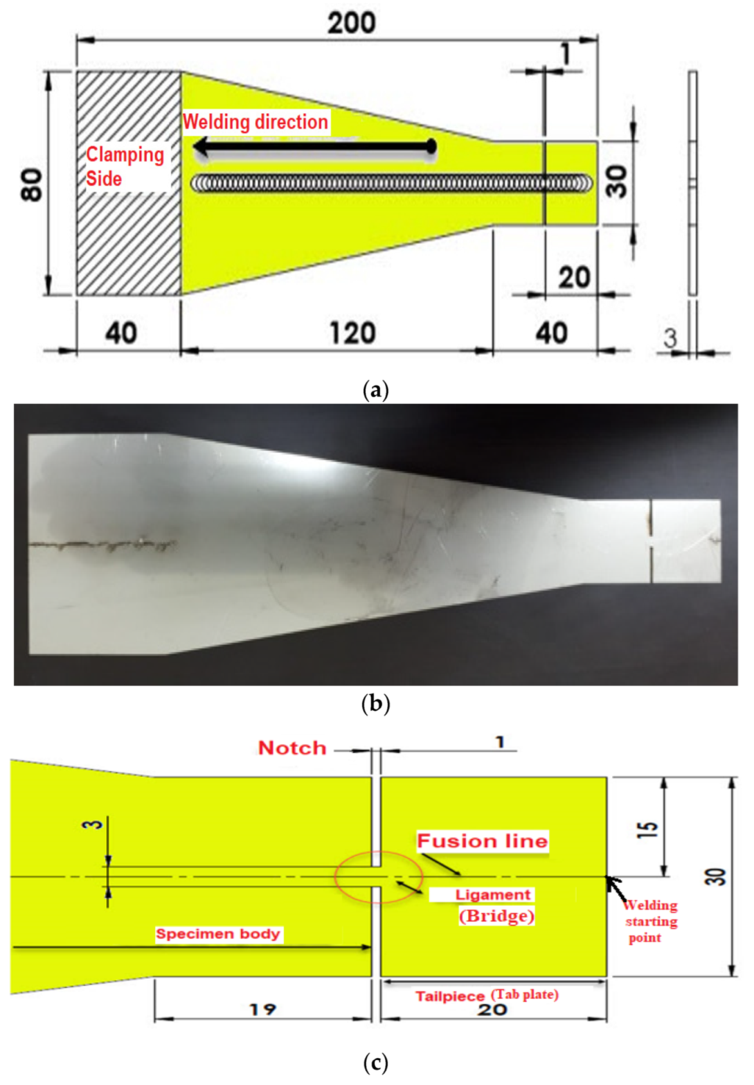
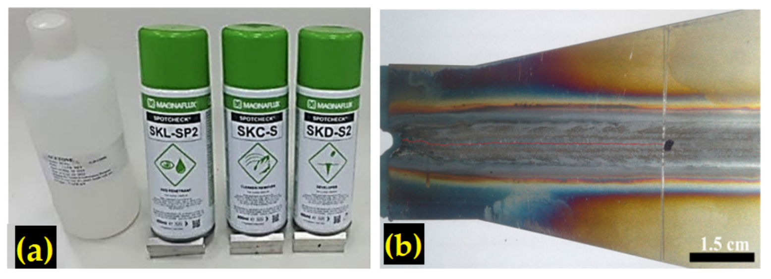
2.2. Welding Procedure

The tests were carried out on ‘trapezoidal’ JWRI specimens prepared using a laser beam machine in the rolling direction of an austenitic stainless steel 316L sheet, the thickness of which was 3 mm. Test specimens were shaped according to Houldcroft′s test pattern and the dimensions were inspired by those used by Kerrouault [21] (see Figure 1a,b). The specimens were notched by a gap of 1 mm at 20 mm from the free edge of the specimen which allows the initiation of the crack propagation during the steady state. The past consisted of a mixture of powders and methanol at a ratio of 1:1 was deposited along the centerline of each specimen. Afterwards, a TIG welding fusion line was performed along this centerline. The arc started from tab plate (narrow part) as shown in Figure 1c. When the fusion reached the bridge (ligament), tab plate (tailpiece) fell, and a steady fusion continued on the test specimen. Then, the hot cracking defect appeared as soon as the bead was initiated. The crack stopped when the width of the specimen reached a critical width. The weld metal was strained in a direction transverse to the welding direction. To ensure the accuracy in well-established test procedure, three tests were carried out for each type of selected powder, including the specimen without deposit powder. The mean values of face side bead width and root bead width were calculated. The crack susceptibility was assessed based on the mean measurements of crack length and mean critical crack width. Spherical powder with average size in the range of 325 mesh was heated separately in the furnace at 180 °C for 1 h to eliminate humidity. The powder was mixed with acetone with (1:1 ratio) and made in the form of paste; a paintbrush was used to apply the mixture on a plain surface to be welded. The acetone was allowed to evaporate, resulting in only the powder being left on the surface of the metal. The mean coating density of the deposit was about 3–4 mg.cm−2, and the paste layer thickness about 0.2 mm. Before the welding operation, the plates were cleaned with acetone.
The test set up is shown in Figure 2a. The specimens were cleaned with acetone. The powders were dried in the furnace for 1 h at 180 °C to eliminate the humidity. Then, a thin layer of the powder mixed with methanol was applied using a brush on the surface subjected to the welding, as shown in Figure 2b. The welds were executed using the motorized TIG welding machine. The electrode used had a diameter of 3.2 mm and the torch was mounted on a motorized carriage, as shown in Figure 2. Figure 2c shows the specimen after welding where the crack is located at the centerline of the coupon.
Welding parameters can have a significant impact on the cracking susceptibility [22]. At higher speeds, the weld center becomes dominated by equiaxed grains, which significantly improves the weldability [23]. Welding parameters were thoroughly chosen to ensure a full penetration weld, a width weld face close to the width weld back, a stable arc and a sound weld. The selected experimental welding parameters are presented in Table 3.
First, the crack in the weld shown in Figure 3b was revealed by the liquid penetrant nondestructive test using the different liquids shown in Figure 3a, and then the crack length was accurately measured.
After the welding process, the samples were cut far from the welding starting point to ensure that the arc welding was stabilized, as shown in Figure 2.
The 316L weld were etched using a glyceregia solution (15 mL HCl + 5 mL HNO3 + 10 mL glycerol). Afterwards, the morphology of the welds was checked using an optical Motic Images plus version 2.0 software integrated with a microscope CAROLINA (CAROLINA, Burlington, NJ, USA). Microstructural characterization of the welded specimens was performed. The assessment of the fusion zone has been analyzed in the locations shown in Figure 4. Micrographs were taken on a JEOL JSM-7600F scanning electronic microscope (SEM) (JEOL, Tokyo, Japan). SEM with energy dispersive spectrometer (EDS) and X-ray diffraction were used for the weld analysis at the lateral solidification hot cracking facies, as shown in Figure 4.

3. Results and Discussions

3.1. Crack Length and Critical Width

Crack lengths and critical widths of the TIG welding lines performed on trapezoidal specimens have been compared and discussed for the following treatments: specimens without any coating powder and specimens coated with different powders (CaF2, LiF, NaF, Ti, Mn, Nb and mixed Nb-Ti). Crack length and critical width were considered when the crack stopped its propagation. The results are listed in Table 4. The results obtained allowed us to find the best coating powder leading to the best resistance to hot cracking. Consequently, the specimen with the highest hot cracking resistance was preferentially chosen for SEM, EDS and XRD analyses.
According to the results shown in Table 3, specimens executed with the fluorides CaF2, LiF and Naf presented, at face and back sides, crack lengths and critical widths significantly lower values than those of the specimen fabricated without powders. This result is ascribed to the higher arc densities obtained with specimens coated with fluorides. Indeed, fluorides migrate to the weld arc leading to a constriction of the arc, according to Howse et al. [24]. The authors suggested that the constriction of the arc will increase the temperature at the anode because of the increase in the current density and of the higher arc voltage. This phenomenon leads to a narrower weld pool [25,26,27] and with minimal residual stresses [28].
This observation is in good agreement with the results obtained by Goodwin [29] when he compared in his study the effects of TIG, electron beam welding (EBW) and laser welding. He concluded that the crack resistance was progressively higher for TIG, EBW and laser welding. In other hand, the increase in arc voltage increases the peak temperature of the weld metal, reduces its cooling rate and the retained δ-ferrite content 316L stainless steel weld metal is increased. Hence, the δ-ferrite content of the 316L stainless steel weld metal is increased. δ-ferrite is benefit to the hot cracking resistance. The latter is increased owing to the fact that the body-centered cubic ferrite structure has a smaller coefficient of thermal expansion than that of the face centered cubic austenite structure; thereby, shrinkage stresses during the cooling stage are reduced [30].
The Mn coated specimen shows more resistance to solidification cracking (cf. Table 3), probably due to the formation of MnS compounds which are characterized by higher melting points. MnS compounds are also able to avoid the formation of FeS film at the grain boundaries [4]. The presence of Mn in high concentrations can contribute to the formation of low-melting eutectic composition type Mn-Mn4P with a solidus temperature of 960 °C, as cited by Arata et al. [31]. We notice that the specimen coated with Mn powder exhibits a crack length lesser comparatively to a TIG weld carried out without any additions.
In our study, the specimen welded with the mixed powders (80% Nb + 20% Ti) exhibited, at face and back sides, the lowest crack length at 22 mm, and the crack stopped at the critical width of 30.8 mm. On the other hand, the specimen coated with pure Nb powder gave, at both sides, crack lengths (25, 24 mm) and critical widths (32, 32 mm) which were lower values than the remaining specimens executed with pure Mn and Ti powders. Hence, specimens executed with Nb powder and those coated with the mixture of powders (80% Nb + 20% Ti) gave the best hot cracking resistance. We notice that the solidification cracking susceptibility decreased with the presence of niobium. This result can be linked to the benefit of Nb, when adding, in the decreasing of the temperature range where both solid and liquid phases coexist [32]. However, many studies [33,34] considered the Niobium as a rich segregant in the form of small particles formed in the interdendritic spaces which refine the dendritic structure, facilitate the filling of the interdendritic spaces and lead to the reduction in hot cracking susceptibility.
The results depicted in Table 4 shows standard deviation (σ), which represents a measure of the amount of variation or dispersion of a set of values. For crack length face side and critical crack width face side measurements, standard deviation is less than 1.2 mm.
Figure 5, Figure 6 and Figure 7 show that a single crack was formed along the centerline of the bead. Neither transverse cracks nor cracks at the heat-affected zone were detected either during TIG welding with or without adding powders.

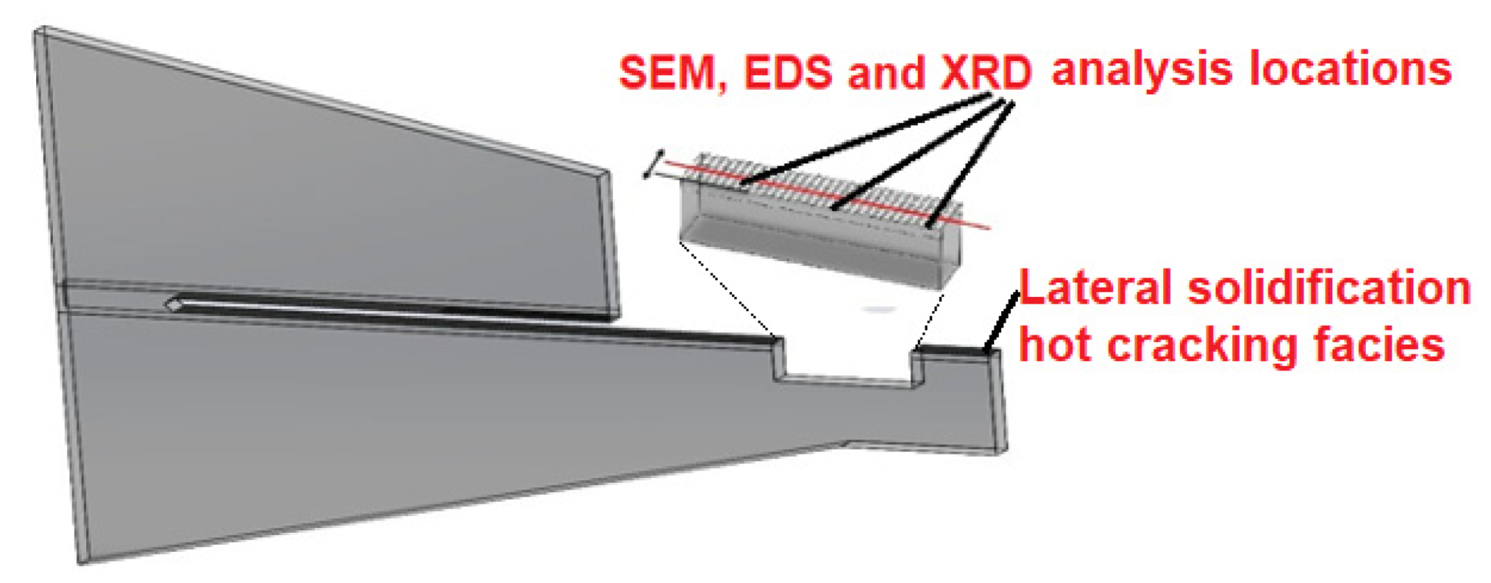
3.2. Microstructure Assessment

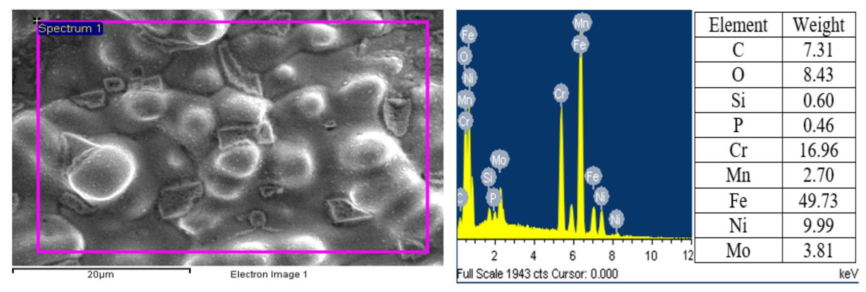
3.2.1. TIG Weld Specimen without Coating Powder

SEM micrographs in Figure 8 shows the dendritic fracture surface of 316L. This is a confirmation that the solidification cracking occurred. The protuberances in the shape of eggs have been formed and surrounded by unfilled cavities. The ratio Creq/Nieq = 1.55 for 316L, hence the material solidified in the ferritic-austenite mode. Even if the weld speed could be considered as relatively high, the δ-ferrite proportion remarkably decreased leading to a segregation of P in the liquid metal. Therefore, precipitants as (Fe, Cr, Ni)3P will be formed and characterized by low melting temperatures (875–1050 °C), as reported by Arata et al. [31]. These precipitants can also widen the brittle range temperature (BTR) at the grain boundary locations. The formation of sulphur-based precipitants is excluded owing to the low sulphur content in the as-received materials. Hence, it is not evident to find sulphides as inclusions or low eutectics as precipitants.
Figure 9 shows EDS spectra of the lateral solidification cracking face of a specimen welded without coating powder. The spectral result allows us to confirm the absence of precipitants or depletion of Cr and Ni elements. We suspect the formation of chromium carbides as (Cr, Fe)23C6 or (Cr, Fe)7C3, and/or molybdenum carbides which gives a brittle aspect to the microstructure. Phosphorus (P), which can induce solidification cracks, was observed. The oxygen(O) present in the EDS result is probably aspired from the environment towards the weld pool during the formation of the crack despite the shield gas protection used at the face side and back side of the weld pool.

3.2.2. TIG Weld Specimen Coated with Nb Powder

We noticed in the micrographs of Figure 10 the multiple bumps in the shape of eggs attesting that the crack solidification occurred. The appearance of backfilling is evident in Figure 10b. The metal liquid fills the spaces between protuberances, leading to a decrease in the crack length and, subsequently, the critical width. This phenomenon is the healing of the crack, which is produced by the addition of niobium.
Figure 11 shows SEM micrograph and EDS spectra of the area containing cracks. The several chemical components such as C, Cr, Fe, Mn, Nb, Ni, and O were detected. We noticed the presence of Nb, C are enhanced and depletion of Cr and Ni. Elements as Nb and C preferentially segregate in the liquid during the solidification stage. Thus, the interdendritic liquid becomes enriched in Nb and C. As the Fe-rich γ dendrites begin to form, less Nb is taken into the solid and, as a result, more is rejected to the liquid. Consequently, the solidification ends at a lower temperature (1223 °C), as mentioned by Dupont [35]. In such cases, BTR is shortened, leading to the healing phenomenon as shown in Figure 12. Thus, the crack length decreases by 2.9 times in comparison to that of the TIG specimens without coating powder. As mentioned above, the suction of oxygen(O) in the weld pool is due to the occurrence of crack.

3.2.3. TIG Weld Specimen Coated with the Mixture of Powders (80% Nb + 20% Ti)

The SEM Image in Figure 13a taken at × 500 magnification was performed perpendicularly to the surface crack, showing a top view of primary dendrites and non-filled voids. Figure 13b is taken at × 2000 and shows the backfilling process leading to healing of the cracks. The liquid metal slips between the secondary and ternary dendrites to bind the dendrites and fill the cavities. Owing to the high welding speed and the rapid solidification which follows, the backfilling of the cavities has not come to end, as shown in Figure 13b.
Figure 14 shows the measurements of EDS taken to have an overview of elements in presence such as S, P, Ti, Nb, Cr and Ni. The elements Ni and Cr show very little tendency for micro segregation. Ni, Cr and Fe are the main constitutes of the matrix. The carbon (C) and niobium (Nb) components are enriched along the crack surface. Most likely, Nb and C preferentially segregate in the liquid during the solidification stage. Thus, the interdendritic liquid becomes enriched in Nb and C during the primary solidification step as explained previously in the case of the Nb-coated specimen. As the Fe-rich γ dendrites begin to form, less Nb is taken into the solid phase and, as a result, more Nb is rejected to the liquid, as shown in SEM micrographs presented in Figure 13b and Figure 15. As mentioned above, the presence of oxygen(O) is ascribed to the apparition of the crack.
In addition to SEM and EDS investigations, specimen coated with the mixture of powders 80% Nb and 20% Ti which gave lesser crack length and critical width was studied via X-ray diffraction (XRD). XRD technique revealed the presence of niobium carbide (Nb2C), (TiO0.6Cr0.2Nb0.0202) phase and cementite (Fe3C) as depicted in Figure 16. The addition of Nb and Ti causes the formation of niobium carbide and phase composed by niobium-titanium-chromium. It also promotes the replacement of the chromium carbide owing to higher affinity of niobium for carbon in comparison to that chromium. As a result, it was confirmed from the XRD results that the eutectic microstructure of niobium carbide and complex phase were produced in the interdendritic regions.
Owing to a high cooling rate, during the last stage of the solidification, low melting-point constituents segregate between solidifying dendrites and form liquid films over the interface of dendrites. This stage of solidification in which both liquid and solid coexist. Study conducted by Seidai et al. [36] confirms the contribution of Nb in reducing BTR.
The addition of niobium with presence of carbon leads to the decrease in BTR as reported in Vallant’s study [33]. Hence, the solidification cracking susceptibility decreases owing to filling of the interdendritic cavities and voids by the precipitants as well as by the continuous supply of liquid metal. This phenomenon leads to the backfilling of cracks which contributes to a decrease in the crack length and the critical width [34].

4. Conclusions

This work aims to investigate the effects on the hot cracking susceptibility of powders such as CaF2, NaF, LiF, Mn, Ti, Nb and mixed Nb-Ti deposited on 316L stainless steel samples when TIG welding is used and compared to sample without any coating powder. A self-restraint hot cracking test with trapezoidal-shaped samples and 3 mm of thickness was carried out. Based on the obtained results, the following conclusions can be drawn:
(i)
TIG welded specimens without coating powder had a greater tendency to solidification cracking than those in which the powders had been pre-deposited.
(ii)
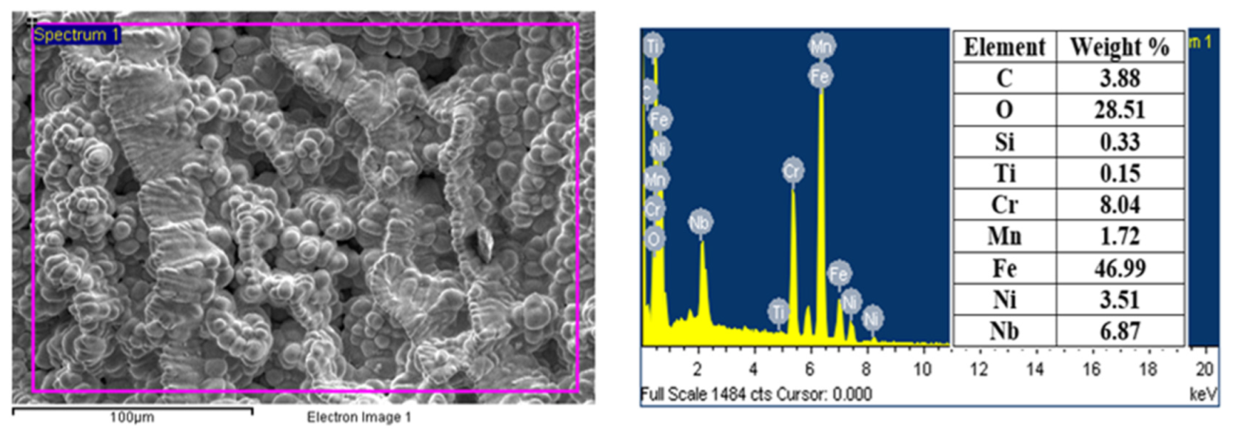
EDS analyses of specimen without coating powder revealed the presence of phosphorus which can lead to the formation of low melting precipitants such as (Fe, Cr, Ni)3P. The formation of these precipitants increased the gap between solidus and liquidus during weld solidification. The strain developed during the welding operation contributed to increasing the crack length.
(iii)
Fluorides and single powders as Mn and Ti had no beneficial contribution in improving the hot cracking resistance.
(iv)
As Nb content increased in the weld metals by coating the samples, the total crack length decreased by 2.9 times and, subsequently, the critical width decreased by 1.65 times.
(v)
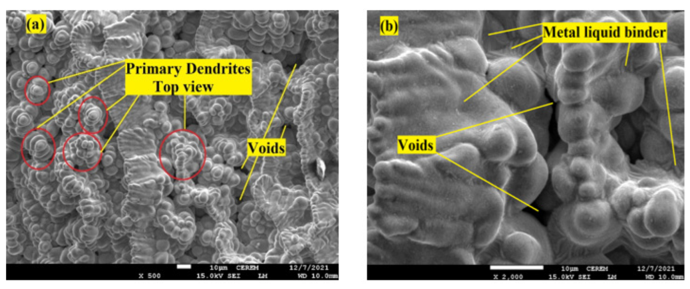
The decrease in solidification cracking susceptibility for specimens coated with Nb or with the mixture of powders (80% Nb + 20% Ti) occurs by adequate backfilling or interdendritic liquid feeding. This compensated both solidification shrinkage and thermal contraction.
(vi)
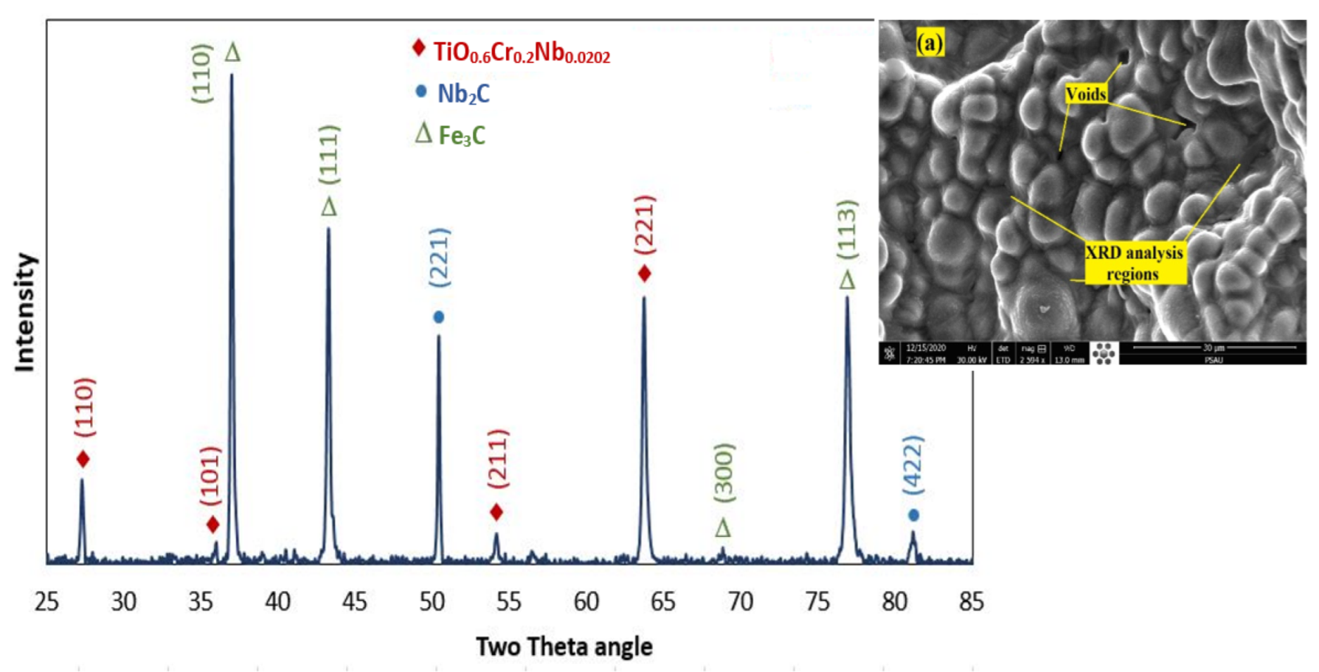
XRD analyses revealed the presence of Niobium carbide (Nb2C), (TiO0.6Cr0.2Nb0.0202) complex phase and cementite (Fe3C) leading to a decreasing in the solidification cracking susceptibility, owing probably to the reduction in the gap between solid and liquid phases during welding operation.

Author Contributions

Conceptualization, K.T. and A.C.H.; methodology, K.T. and A.C.H.; software, K.T. and A.C.H.; validation, K.T., A.O. and H.S.A.; formal analysis, K.T.; investigation, K.T., H.S.A., A.O. and A.C.H.; resources, A.I.; data curation, K.T. and A.I.; writing—original draft preparation, K.T.; writing—review and editing, K.T., A.O., A.C.H. and A.I.; visualization, K.T.; supervision, K.T.; All authors have read and agreed to the published version of the manuscript.

Funding

This work is funded by the Ministry of Education through the project number (IF-PSAU-2021-01-18492).

Institutional Review Board Statement

Not applicable.

Informed Consent Statement

Not applicable.

Data Availability Statement

Data will be available upon request through the corresponding author. The data used to support the findings of this study are included within the article.

Acknowledgments

The authors extend their appreciation to the Deputyship for Research & Innovation, Ministry of Education in Saudi Arabia for funding this research work through the project number (IF-PSAU-2021-01-18492).

Conflicts of Interest

The authors declare no conflict of interest.

References

  1. Suutala, N.; Takalo, T.; Moisio, T. Single-phase ferritic solidification mode in austenitic-ferritic stainless steel welds. Met. Trans. A. 1979, 10, 1183–1190. [Google Scholar] [CrossRef]
  2. Takalo, T.; Suutala, N.; Moisio, T. Austenitic solidification mode in austenitic stainless steel welds. Met. Trans. A 1979, 10, 1173–1181. [Google Scholar] [CrossRef]
  3. Saluja, R.; Moeed, K.M. Depiction of detrimental metallurgical effects in grade 304 austenitic stainless steel arc welds. Int. J. Mech. Prod. 2018, 8, 207–218. [Google Scholar]
  4. Ogawa, T.; Tsunetomi, E. Hot Cracking Susceptibility of Austenitic Stainless Steels. Weld. Res. Suppl. 1982, 3, 82–93. [Google Scholar]
  5. Lippold, J.C.; Kotecki, D.J. Welding Metallurgy and Weldability of Stainless Steels, 1st ed.; Hoboken, John Wiley & Sons Inc.: Hoboken, NJ, USA, 2005. [Google Scholar]
  6. Makarov, E.L.; Herold, H.; Streitenberger, M.; Pchennikov, A. Preventing hot cracking in end sections of long welds in one-sided, multi-arc, submerged-arc welding. Weld. Int. 2000, 14, 305–309. [Google Scholar] [CrossRef]
  7. Seung, H.L. A Hot Cracking on Dissimilar Metal Weld between A106Gr.B and A312 TP316L with Buttering ERNiCr-3. Metals 2019, 9, 533. [Google Scholar]
  8. Wilken, K.; Kleistner, H. The classification and evaluation of hot cracking tests for weldments. Weld. World 1990, 28, 134–143. [Google Scholar]
  9. Nelson, T.W.; Lippold, J.C.; Lin, W.; Baeslack, W.A. Evaluation of the circular patch test for assessing weld solidification cracking, part I—Development of a test method. Weld. J. 1997, 76, 110–119. [Google Scholar]
  10. Matsuda, F.; Nakata, K.; Tsukamoto, K.; Kohzoh, A. Effect of additional alloying element on weld solidification crack susceptibility of Al-Zn-Mg alloy. Trans. JWRI 1983, 12, 93–102. [Google Scholar]
  11. Matsuda, F.; Nakata, K.A. New test specimen for self-restraint solidification crack susceptibility test of electron-beam welding bead—fan shaped cracking test. Trans. JWRI 1982, 11, 87–94. [Google Scholar]
  12. Ploshikhin, V.; Prikhodovsky, A.; Makhutin, M.; Ilin, A.; Zoch, H.W. Integrated mechanical-metallurgical approach to modeling of solidification cracking in welds. In Hot Cracking Phenomena in Welds; Böllinghaus, T., Herold, H., Eds.; Springer: Berlin/ Heidelberg, Germany, 2005; pp. 223–244. [Google Scholar]
  13. Wenbin, W.; Li, X.; Dan, W.; Qin, M.; Yan, H.; Guanzhi, H.; Yucheng, L. A New Test Method for Evaluation of Solidification Cracking Susceptibility of Stainless Steel during Laser Welding. Materials 2020, 13, 3178. [Google Scholar]
  14. Abu-Aesh, M.; Taha, M.; El–Sabbagh, A.S.; Lutz, D. A Proposed Mechanism of Hot-Cracking Formation During Welding Fan-Shaped Test Specimen Using Pulsed-Current Gas Tungsten Arc Welding Process. Eng. Appl. Sci. 2021, 6, 86–104. [Google Scholar] [CrossRef]
  15. Dixon, B.F. Control of Magnetic Permeability and Solidification Cracking in Welded Nonmagnetic Steel. Weld. J. 1989, 68, 171–180. [Google Scholar]
  16. Cross, C.E.; Böllinghaus, T. The effect of restraint on weld solidification cracking in aluminum. Weld. World 2006, 50, 51–54. [Google Scholar] [CrossRef]
  17. da Silva, C.L.M.; Americo, S. Performance assessment of the (Trans) Varestraint tests for determining solidification cracking susceptibility when using welding processes with filler metal. Meas. Sci. Technol. 2004, 15, 1–9. [Google Scholar] [CrossRef]
  18. Nam, S.; Jung, I.-H.; Kim, Y.-M. Effect of TiN Spray Coating on Cracking Susceptibility and Energy Absorption in Laser Welding of Aluminum Alloys. Metals 2020, 10, 1657. [Google Scholar] [CrossRef]
  19. Suutala, N.; Takalo, T. Ferritic-Austenitic Solidification Mode in Austenitic Stainless Steel Welds. Met. Trans. A 1980, 11, 717–725. [Google Scholar] [CrossRef]
  20. Kotecki, D.J.; Siewert, T.A. WRC-1992 Constitution Diagram for Stainless Steel Weld Metals: A Modification of the WRC-1988 Diagram. Weld. Res. Suppl. 1992, 5, 171–178. [Google Scholar]
  21. Kerrouault, N. Fissuration à Chaud en Soudage d’un Acier Inoxydable Austénitique. Ph.D. Thesis, Ecole Centrale de Paris, Paris, France, 2000. [Google Scholar]
  22. Hunziker, O.; Dye, D.; Roberts, S.M.; Reed, R.C. A coupled approach for the prediction of solidification cracking during the welding of superalloys. In Hot Cracking Phenomena in Welds; Springer: Berlin/ Heidelberg, Germany, 2005; pp. 299–319. [Google Scholar]
  23. Coniglio, N.; Cross, C.E. Towards Establishment of Weldability Testing Standards for Solidification Cracking. In Hot Cracking Phenomena in Welds; Springer: Berlin/ Heidelberg, Germany, 2016; pp. 37–66. [Google Scholar]
  24. Howse, S.; Lucas, W. Investigation into arc constriction by active fluxes for tungsten inert gas welding. Sci. Technol. Weld. Join. 2000, 5, 189–193. [Google Scholar] [CrossRef]
  25. Patel, D.; Jani, S. Techniques to weld similar and dissimilar materials by ATIG welding—An overview. Mater. Manuf. Process. 2021, 36, 1–16. [Google Scholar] [CrossRef]
  26. Touileb, K.; Hedhibi, A.C.; Djoudjou, R.; Ouis, A.; Benselama, A.; Albaijan, I.; Hany, S.A.; Mohamed, M.Z.A. Mechanical, Microstructure, and Corrosion Characterization of Dissimilar Austenitic 316L and Duplex 2205 Stainless-Steel ATIG Welded Joints. Materials 2022, 15, 2470. [Google Scholar] [CrossRef]
  27. Touileb, K.; Djoudjou, R.; Hedhibi, A.C.; Ouis, A.; Benselama, A.; Albaijan, I.; Hany, S.A.; Ubair, A.S. Comparative Microstructural, Mechanical and Corrosion Study between Dissimilar ATIG and Conventional TIG Weldments of 316L Stainless Steel and Mild Steel. Metals 2022, 12, 635. [Google Scholar] [CrossRef]
  28. Vishawa, B.; Ankur, G.; Chanda, P. Role of A-TIG process in joining of martensitic and austenitic ateels for ultra-supercritical power plants—A state of the art review. Nucl. Eng. Technol. 2022, 54, 1–16. [Google Scholar]
  29. Goodwin, G.M. The Effects of Heat Input and Weld Process on Hot Cracking in Stainless Steel. Weld. J. 1988, 64, 88–94. [Google Scholar]
  30. Huang, H.Y.; Shyu, S.W.; Tseng, K.H.; Chou, C.P. Evaluation of TIG flux welding on the characteristics of stainless steel. Sci. Technol. Weld. Join. 2005, 10, 566–573. [Google Scholar] [CrossRef]
  31. Arata, Y.; Matsuda, F.; Katayama, S. Solidification Crack Susceptibility in Weld Metals of Fully Austenitic Stainless Steels (Report II): Effect of Ferrite, P, S, C, Si and Mn on Ductility Properties of Solidification Brittleness. Trans. JWRI 1977, 6, 105–116. [Google Scholar]
  32. Wenlin, M.; Zhung, X.; Shanping, L.; Dianzhong, L.; Yiyi, L. Effect of Nb content on microstructure, welding defects and mechanical properties of NiCrFe-7 weld metal. Acta Metal Sin. 2015, 15, 230–238. [Google Scholar]
  33. Vallant, R. The Influence of Different Nb-Contents on the Hot Cracking Susceptibility of Ni-Base Weld Metals Type 70/20. In Hot Cracking Phenomena in Welds; Springer: Berlin/ Heidelberg, Germany, 2005; pp. 141–164. [Google Scholar]
  34. Lee, H.T.; Kuo, T.Y. Effects of niobium on microstructure, mechanical properties, and corrosion behaviour in weldments of alloy 690. Sci. Technol. Weld. Join. 1999, 4, 247–256. [Google Scholar] [CrossRef]
  35. Dupont, J.N. Microstructural Development and Solidification Cracking Susceptibility of a Stabilized Stainless Steel. Weld. J. Res. Suppl. 1999, 7, 253–263. [Google Scholar]
  36. Seidai, U.; Kota, K.; Shun, T.; Hiroshige, I. Relationship between Alloy Element and Weld Solidification Cracking Susceptibility of Austenitic Stainless Steel. ISIJ Int. 2019, 59, 1323–1329. [Google Scholar]
Figure 1. Trapezoidal specimen (a,b) and tailpiece (Tab plate) details (c). Dimensions in mm.
Metals 12 01225 g001
Figure 2. Test setup sketch (a), specimen before welding (b) and specimen after welding (c).
Metals 12 01225 g002
Figure 3. Liquid penetrant kit used after welding (a) on the weld line (b).
Metals 12 01225 g003
Figure 4. Microstructural characterization analysis locations.
Metals 12 01225 g004
Figure 5. TIG-welded specimen without adding powders, face side.
Metals 12 01225 g005
Figure 6. Welded specimen coated with Nb powders, face side (a), enlarged of marked area (b) and back side of enlarged marked area (c).
Metals 12 01225 g006
Figure 7. Welded specimen coated with the mixture of powders (80% Nb + 20% Ti), face side (a), enlarged of marked area (b) and back side of enlarged marked area (c).
Metals 12 01225 g007
Figure 8. SEM micrographs of crack face of TIG weld specimen without coating powder (a) (×1000) and (b) (×2000).
Metals 12 01225 g008
Figure 9. EDS spectral analysis in the lateral solidification cracking face of the specimen welded without coating powder.
Metals 12 01225 g009
Figure 10. SEM micrographs of crack face of TIG weld specimen coated with Nb powder (a) (×1000) and (b) (×2000).
Metals 12 01225 g010
Figure 11. EDS spectral analysis in the lateral solidification hot cracking face in TIG weld coated by pure Nb powder.
Metals 12 01225 g011
Figure 12. SEM micrograph of solidification hot cracking face in TIG weld coated by pure Nb powder (×500).
Metals 12 01225 g012
Figure 13. Micrograph of crack face of TIG weld specimen coated with the mixture of powders (80% Nb + 20% Ti) (a) (×500) and (b) (×2000).
Metals 12 01225 g013
Figure 14. EDS spectral analysis in the lateral solidification hot cracking face in TIG weld coated by the mixture of powders (80% Nb + 20% Ti).
Metals 12 01225 g014
Figure 15. SEM micrograph at the solidification cracking surface in TIG weld coated with the mixture of powders (80% Nb + 20% Ti) × 2500.
Metals 12 01225 g015
Figure 16. X-Ray Diffraction (XRD) pattern in the solidification hot cracking surface in TIG weld coated with the mixture of powders (80% Nb + 20% Ti), (a) XRD analysis regions × 2500.
Metals 12 01225 g016
Table 1. Chemical composition of 316L stainless steel.
ElementsCMnSiPSCrNiMoNCuFe
Weight %0.0261.470.420.0340.001616.6010.082.140.0440.50Balance
Table 2. Powders, melting and evaporation temperatures.
PowdersMelting Temperature (°C)Evaporation Temperature (°C)
CaF214182533
LiF8481673
NaF9931700
Mn12462061
Nb24774744
Ti16683287
Table 3. Welding parameters.
ParameterValue
Welding current150 A
Voltage11 V
Efficiency75%
Welding speed28 cm/min
Heat provided265 J/mm
Shield gas faceArgon 8 L/min
Shield gas backsideArgon 6 L/min
Electrode diameter2.4 mm
Electrode typeTungsten thoriated 2%
Electrode tip angle45°
Arc length2 mm
Welding modeNegative direct current electrode
Table 4. Weld morphology, crack length, critical width and standard deviation.
TIG WeldNumber of TestsMean Face Width Weld Bead (mm)Mean Back Width Weld Bead
(mm)
Mean Crack Length Face Side
(mm)
Standard Deviation σ
For Crack Length Face Side
Mean Crack Length Back Side
(mm)
Mean Critical Crack Width Face Side
(mm)
Standard Deviation σ
For Critical Crack Width Face Side
Mean
Critical Crack Width Back Side
(mm)
Without powder385740.887652.50.7853.3
CaF2364490.795042.30.7243.7
LiF365480.964941.71.0342.1
NaF364401.004438.31.0840.0
Ti365561.075645.01.171.17
Mn366450.894940.41.111.11
Nb366250.8224320.840.84
80%Nb + 20%Ti376220.8222310.891.14
Publisher’s Note: MDPI stays neutral with regard to jurisdictional claims in published maps and institutional affiliations.

