Article

Effects of Deep Rolling on the Microstructure Modification and Fatigue Life of 35Cr2Ni4MoA Bolt Threads

1
AVIC Changhe Aircraft Industry (Group) Co., Ltd., Jingdezhen 333000, China
2
Department of Mechanical Engineering, Tsinghua University, Beijing 100084, China
3
State Key Laboratory of Tribology, Tsinghua University, Beijing 100084, China
*
Author to whom correspondence should be addressed.
Metals 2022, 12(7), 1224; https://doi.org/10.3390/met12071224
Submission received: 9 June 2022 / Revised: 13 July 2022 / Accepted: 17 July 2022 / Published: 20 July 2022

Abstract

:
Stress concentration on a bolt thread, resulting from its own special shape, poses a threat to the fatigue strength of the bolt, which directly affects the safety and reliability of aircraft. In this paper, deep rolling was applied to a bolt thread to improve its fatigue resistance. The properties of the plastic deformation layer, including the surface morphology, microstructure, hardness, and residual stress, as well as the fatigue life of the bolt, were characterized by means of SEM, white light interferometer, EBSD, and fatigue tests. The results showed that the surface roughness of the bottom of the thread was reduced to 0.255 μm, and a plastic deformation layer of about 300 μm in depth was formed after rolling. A more compact streamlined fibrous microstructure, composed of refined grains, with increased dislocation density and hardness and decreased tensile residual stress, was formed in the plastic deformation layer. The fatigue life of the bolts after rolling increased by about 113%, evidencing the comprehensive result of these microstructure modifications.

1. Introduction

Joints, including all kinds of bolts, are widely used in the aviation industry, and their reliability plays a critical role in the safety and reliability of the overall aircraft. Such bolts are subjected to heavy alternating shear and bending loads during service, and fatigue failure often occurs [1], especially at the threaded part of the bolt. There has been an ever-growing demand for higher-strength bolt materials in recent years. The particularity of the shape of the thread root often brings about stress concentration and, therefore, the fatigue failure of the bolt, giving rise to the weak areas of the bolt [2]. As a result, improvements to the fatigue strength of the thread are key to improving the fatigue performance of the bolt, and the development of such strengthening methods is of great significance to ensure the safety and reliability of aircraft.
Deep rolling has been proven to be an effective surface-strengthening method to promote surface finish, hardness, and compressive residual stress, which are all closely related to the improvement of fatigue performance [3,4,5,6,7,8,9,10,11,12,13,14,15,16,17,18,19,20,21,22,23,24,25,26,27]. For instance, ultrasonic rolling was applied to a Ti-6Al-4V titanium alloy, and it was found that the hardness and residual compressive stress increased by 34% and 142%, respectively [5]. Also, a certain degree of plastic deformation was reported by Li et al. in the surface of materials after rolling, which promoted grain refinement and improved the dislocation density of the surface-modified layer [6]. A new type of ultrasonic rolling was developed by Cheng et al. to strengthen the threaded specimen made by AerMet100 high-strength steel. After treatment, the surface roughness of the material was reduced by 50%, and a higher compressive residual stress level and a deeper refined layer were obtained in contrast to the conventional method [12]. Balasubramanian reported that higher work hardening and deeper residual stress distributions on the surface of a nickel base superalloy were caused by the severe deformation layer and grain refinement of the material after rolling [13]. The improvement of surface properties after rolling is in favor of the strength and fatigue resistance of the materials. It was reported by Lai et al. that the fatigue strength of 33Cr23Ni8Mn3N (23-8N) austenitic steel increased by 38.3% after rolling [16]. Similarly, Liu et al. [18] found that the tensile strength, yield strength, and fatigue life of A473M martensitic stainless steel increased by 40%, 22%, and 184%, respectively, after rolling. However, despite the fact that these studies focused on the improvement of microstructures and other mechanical properties via rolling, there is a lack of comprehensive research connecting this with surface morphology, microstructure, and mechanical properties so far. In addition, most research on deep rolling has mainly been conducted on smooth and flat sample materials, such as titanium alloy [4,5,6,7,11,14,23,27], aluminum alloy [20], superalloy [13,21,22], and stainless steel [18], while there is less research on curved specimens with larger stress concentrations, which is more widely used in practical applications [12]. In response to the urgent need for higher fatigue life and reliability in bolt joints, a comprehensive study on the fatigue properties of the threads of bolts after rolling is necessary. In this paper, deep rolling was carried out on bolt threads made from 35Cr2Ni4MoA steel, and changes in surface morphology, microstructure, hardness, and residual stress, as well as the fatigue performance of the thread after rolling, were investigated. Microstructure changes along the depth direction after rolling were further investigated. Finally, the corresponding strengthening mechanism is discussed based on the results.

2. Materials and Methods

2.1. Materials and Sample Preparation

The aircraft-used bolts tested in this study were made from 35Cr2Ni4MoA steel (mass %: C~0.37, Mn~0.37, Si~0.41, Cr~1.75, Ni~4.1, Mo~0.20, S~0.006, P~0.006, and Fe is balanced). This is a low alloy steel, treated by hardening and tempering, which combines high strength and toughness, making it widely used in aerospace structural applications. The thread of the ‘as-received’ bolt was fabricated by turning, and the cutting parameters were set as follows: the rotating speed of the sample was 1500 r/min, the cutting depth was 0.05 mm, and the feed speed was 0.003 mm/r. The dimension of the bolts is shown in Figure 1a, and some of them were rolled for further tests. The apparatus of deep rolling was an accessory equipped with the machine tool (KEDE, YDZ-40, China), as shown in Figure 1b,c, and the parameters of the rolling used in this study are listed in Table 1.

2.2. Experimental Methods

2.2.1. Surface Topography Observation

Scanning electron microscopy (SEM) (FEI, QUANTA200 FEG, Netherlands) was used to observe the surface morphology of the bottom of the bolt thread (hereafter referred to as thread) after turning and rolling, and a ZYGO NexView 3D white light interferometry surface topography instrument was used for surface roughness analysis and 3D surface morphology characterization.

2.2.2. Microstructure Characterization

A scanning electron microscope and an optical microscope (OM) (Olympus, FV1200MPE, Japan) were used to observe the cross-section microstructure of the thread after turning and rolling. Samples were prepared by wire cutting in the direction perpendicular to the thread, ensuring that at least one side of the sample contained the thread tooth area. The thread tooth side of the sample was polished with sandpaper of different mesh sizes in turn and mechanically polished to ‘scratch-free’. Then the surface was etched with 10% HNO3-CH3CH2OH metallographic etching solution for 20 s and ultrasonically cleaned with acetone.
Electron backscatter diffraction (EBSD) was used to analyze the microstructure of the thread in depth after rolling. EBSD tests were carried out on the EBSD accessory of the PHI710 Auger spectrometer. The acceleration voltage was 15 kV, the scanning range was 30×30 μm, and the scanning step was 0.08 μm. Due to the sensitivity of the EBSD tests on surface quality, the surface was also polished by an argon ion beam to remove the deteriorated layer induced by polishing. Argon ion beam polishing was performed on a Leica EM TIC 3X for 4 hours with an acceleration voltage of 5.5 kV and a current of 1.5 mA. After EBSD tests, the kernel average misorientation (KAM) and inverse pole figure (IPF) diagrams were constructed with the EBSD dataset in EDAX OIM software.

2.2.3. Microhardness Test

Microvickers hardness tester (Future-Tech FM-810, Japan) was used for the hardness tests. For each measurement, a load of 0.49 N was applied, and the pressure was held for 10 s. Measurements were made at intervals of 40 μm along the depth direction, starting at a location very close to the surface, and carried out seven times at the same depth.

2.2.4. Residual Stress Test

Residual stress tests were performed using an X-ray stress analyzer (Xsress3000, Finland). Considering the special shape of the thread, the tilt method was chosen to eliminate the effect of the curved surface on the results. The collimator diameter was 0.8 mm. The axial and tangential residual stresses on the surface of the thread were measured respectively, and six random areas were tested.

2.2.5. Fatigue Test

The fatigue test was carried out using the MTS fatigue testing machine. The test adopts cyclic axial loading, a stress ratio of R = 0.1, a tightening force of bolt installation of 20 N⸳m, and an initial load of 9.78 kN ± 8 kN. After each cycle of 300,000 times, if the bolt does not break, the test continues to increase the load by 20% until it breaks. The test included the five received bolts and the five rolled bolts.

3. Results and Discussion

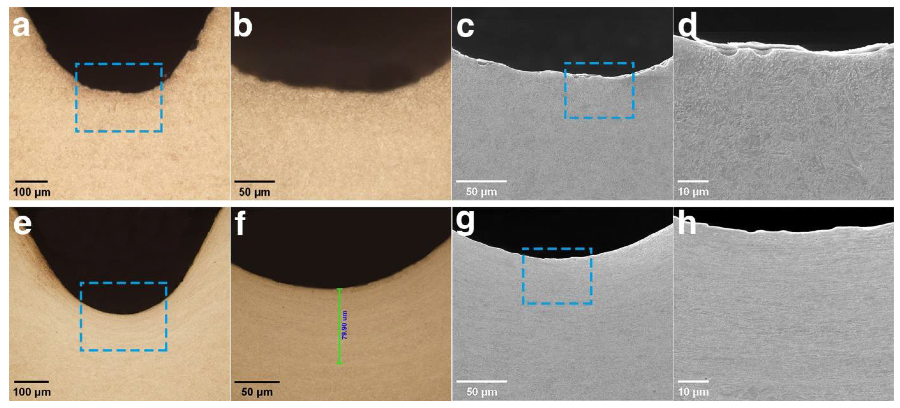
3.1. Surface Topography Observation

Surface morphology is one of the important factors that affects the fatigue life of threads. A comparison of the surface morphology between the thread after turning (the final process of the as-received bolt) and after rolling, under OM and SEM, is given in Figure 2. It can be observed from Figure 2a,b that there are obvious cutting traces on the surface of the thread after turning, and most of these cutting traces are in the shape of grooves. Large stress concentrations are most likely to occur at these grooves under the alternating load, which facilitates the initiation and propagation of fatigue cracks on the surface of the thread, leading to early fatigue failure. After rolling, the surface of the thread became much smoother with the disappearance of the original unfavorable grooves, as shown in Figure 2d,e. The surface roughness (Sa) of the two samples was calculated based on the flattened three-dimensional topography after turning and rolling, measuring 0.997 μm and 0.255 μm for the thread after turning and rolling, respectively. The decrease in surface roughness was due to the plastic flow under the action of external pressure during rolling, which can be concluded as a ‘peak-cutting and trough-filling’ effect. As a result, the surface became smoother, which helps to reduce the stress concentration level and delay the initiation of fatigue cracks [10,11,17].

3.2. Microstructure Characterization

The maximum degree of plastic deformation is formed on the surface of the material after rolling, and it gradually decreases with depth [12]. Figure 3 shows the cross-section metallographic structure of the threads on the as-received and rolled bolts via OM and SEM. The surface microstructure of the thread on the as-received bolt remains the same after turning, as shown in Figure 3a–c. It is composed of tempered sorbite, with alloy carbides distributed at the grain boundaries, which contributes to high strength and hardness. In contrast, it is obvious from Figure 3e that plastic flow occurred on the surface of the thread after rolling, and a streamlined fibrous microstructure was formed along the thread direction with a depth of about 80 μm. The grains in this region are elongated and twisted along the deformation direction under the rolling force; hence, the surface microstructure is refined, as shown in Figure 3f. The refinement of the surface microstructure can help delay the initiation of cracks as they tend to initiate from the surface of the material. In the meanwhile, the compact high-strength layer formed on the surface of the thread is also beneficial for improving the mechanical properties of the bolt thread [19].
During rolling, a large number of crystal defects were generated under severe plastic deformation, accompanied by dislocation multiplication and annihilation. Therefore, a high density of dislocation aggregated at the surface of the thread [5,25]. As the depth from the surface increases, the density of the dislocation decays, corresponding to a smaller plastic deformation level until it is consistent with the undeformed region. Considering that the resolutions of OM and SEM are not large enough to observe the submicron scale defects, EBSD was applied to characterize the microstructure change in the plastic deformation region. In addition, this was expected to measure the exact depth of the overall plastic deformation region by the change in dislocation density, which is a reflection of the strengthening effect on the bolt thread. Figure 4a–f show the distribution of KAM at different distances from the surface of the thread. KAM is defined as the local average orientation difference within the grain, and it has been proven to be positively associated with the dislocation density in the scanning area [28,29]. In other words, a greater KAM value means a higher dislocation density and vice versa. Due to the severe lattice distortion resulting from the plastic deformation, the Kikuchi patterns at some points are too poor to be resolved, which are represented by black points, especially in Figure 4a–c. Such a phenomenon can be seen to be alleviated in Figure 4d,e. A frequency distribution histogram is given in Figure 4g to reveal these differences in the dislocation density more intuitively. It can be found that there are a bulk of points with a KAM value greater than 1 (represented by yellow points in the KAM map) in the superficial layer after rolling, while the KAM value of the interior region is basically less than 1 (represented by blue and green points in the KAM map), indicating that a large number of dislocation multiplication took place in the plastic deformation region after rolling. Also, it can be observed that the KAM distribution in the depth area 300 μm from the surface is very close to that in the undeformed region. Therefore, it can be inferred that the depth of the plastic deformation region reaches about 300 μm after rolling.
Figure 5a–f show the IPFs at different distances from the surface, and the grain sizes in these areas were counted and can be seen in the attached histograms. Areas within 100 μm from the surface are mainly composed of fine grains, with diameters ranging from a minimum of 0.4 μm to around 1.2 μm, and the proportion of these fine grains gradually decreases in deeper areas, which is obviously different from the undeformed region. After rolling, the grains in the superficial layer were elongated and twisted, and some of these original grains were refined into several small grains. It should be noted that the depth of the streamlined fibrous microstructure observed in the OM images is about 80 μm, and this is close to the depth of the fine grain region, which is around 100 μm. The mechanism for grain refining can be explained as follows. The dislocations became denser as the strain increased during rolling; they are generated, rearranged, and annihilated via dislocation movements under plastic deformation to reduce the system’s energy. Some of these dislocations tangled with each other and formed cellular structures, which then developed into sub-grains. When the strain kept increasing, the sub-grains turned into new grains with small or big angle grain boundaries [25,30,31]. As a result, the original grains are divided into several small grains or sub-grains under plastic deformation, thereby refining the grains. Grain and sub-grain boundaries (identified by the criterion that the misorientation angle is smaller than 3°) are marked by black and red lines in the IPFs. There are both grains and sub-grains that compose these fine grains, which can be recognized near the grain boundaries of the original grains. Grain and sub-grain boundary lengths and fractions were also counted (Figure 5g,h). Both the grain and sub-grain boundary length peak in an area close to the surface as a result of the grain refinement. The effect of plastic deformation on grain refining fades with the increase in depth; hence, the grain size and grain and sub-grain boundary lengths in the interior areas gradually decrease with depth and become close to the undeformed region. In addition, the pole figure depicted in Figure 5i,j, corresponding to the areas in Figure 5a,f, indicates that no texture is formed, whether after turning or after rolling.
During the process of cyclic fatigue loading, the slipping of dislocations plays a key role in the fatigue crack nucleation in metal materials [10]. Microstructure modifications of the surface material induced from rolling, including the formation of a compact streamlined fibrous microstructure, increases the dislocation density, and the elongation and refining of grains will help to hinder the slipping of dislocations, thereby delaying the nucleation of fatigue cracks [4,23] and improving the fatigue performance of the bolt thread.

3.3. Microhardness Test

Figure 6 shows the contour map of the hardness of the threads along the depth direction. The hardness of the thread after turning ranges from 420 to 460 HV unevenly, indicating that the microstructure of the surface of the thread was not affected by the turning process. In contrast, the hardness of the thread after rolling was significantly increased, which peaks at the surface of the thread and decreases gradually with depth. In addition, the transverse distribution of the hardness of the rolled thread became more uniform.
The enhancement of near-surface hardness after rolling the thread is mainly due to dislocation multiplication and microstructure refinement [19,24]. The strength of the material can be predicted by considering the contributions from the dislocation density and grain size with plastic deformation, as shown in the following equation [26,32]:
σ f = σ 0 + k d f p 1 / 2 + α G b ρ 1 / 2
where σf is the strength, σ0 is a constant stress called friction stress, k is the Hall–Petch constant, dfp is the mean free path of dislocations, α is a constant, G is the shear modulus, b is the modulus of the Burgers vector, and ρ is the dislocation density. According to the equation, the hardness of the material increases with the increase of dislocation density and the decrease of grain size. Severe plastic deformation caused by rolling results in a high dislocation density and a large number of fine grains in the near-surface region, as can be seen in Figure 4 and Figure 5. These microstructure modifications help to hinder the dislocation motion and therefore improve the hardness of the material.

3.4. Residual Stress Test
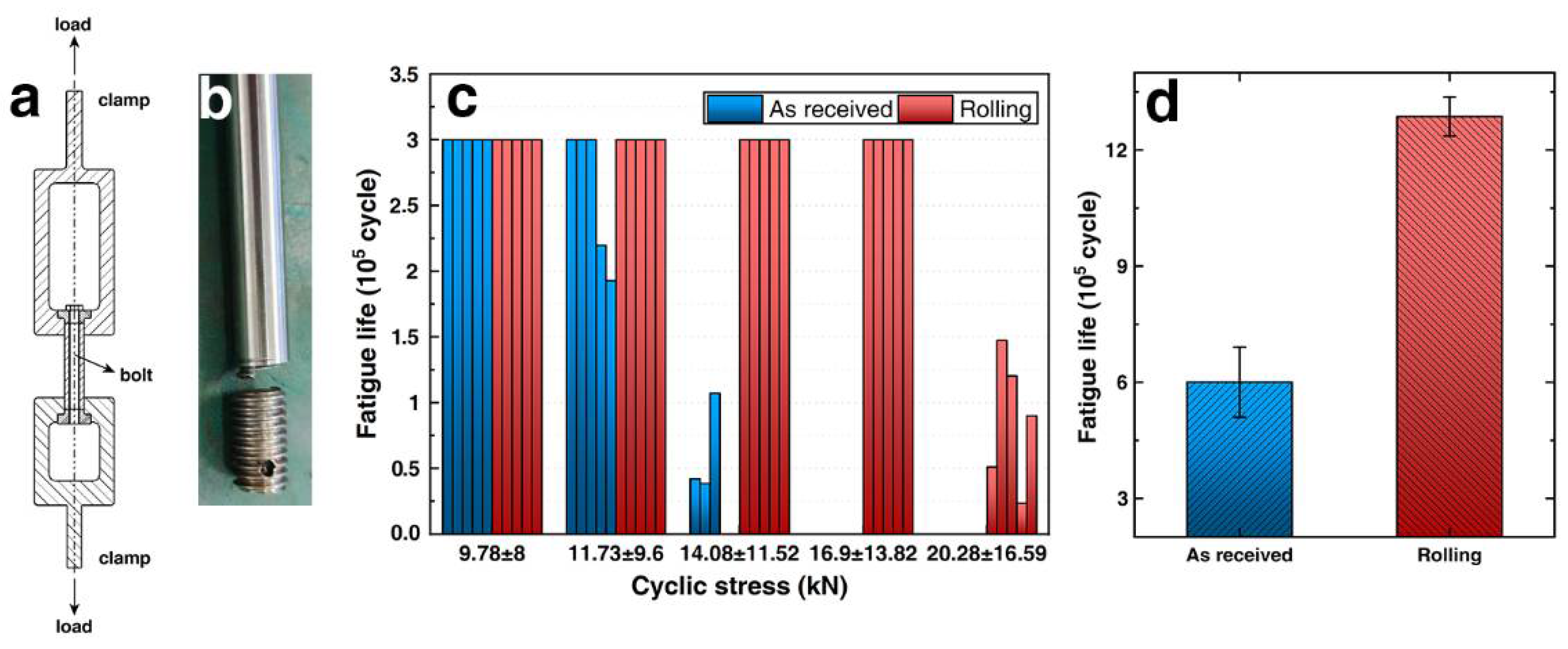
Axial and tangential residual stresses are measured at six points along the surface of the threads after turning and rolling, respectively, as shown in Figure 7. After turning, tensile residual stress is induced at the surface of the thread, the average of which was 553.4 MPa and 893.2 MPa for the axial and tangential residual stresses, respectively. Compared with the turned thread, the axial and tangential stresses at the surface of the thread after rolling were significantly reduced by 40% and 29%, respectively, with the stress distributed more evenly with the reduction in the standard deviation. The fibrous microstructure was formed in the surface layer of the rolled thread due to plastic deformation, which is shown in Figure 3d–f. During rolling, the tensile stress was introduced in the elastic deformation zone adjacent to the fibrous microstructure. After the removal of the external load, the recovery of the elastic deformation resulted from the introduction of compressive residual stress in the fibrous microstructure. However, based on the measurement, the original state of the tensile residual stress was too high to be relaxed by deep rolling. Research has shown that residual stress is strongly affected by turning conditions and material properties [12,33,34,35]. To be specific, the tensile residual stress becomes higher with a higher cutting speed and feeding rate. In addition, the hard machinability of hard materials also induces higher tensile residual stress. As a result, the high tensile residual stress on the surface of the thread after turning is difficult to avoid.
It is known that the existence of compressive residual stress in the thread will decelerate the propagation of fatigue cracks, while the existence of tensile residual stress will aggravate the initiation and propagation of cracks. At the same time, the superposition of negative residual stress and applied stress will reduce the actual tensile stress level in the surface area of the material [36]. The tensile residual stress of the thread significantly decreased after rolling, which is of benefit to the fatigue behavior of bolt threads.

3.5. Fatigue Test

Figure 8 shows the loading method and results of the fatigue test. All bolts in the fatigue tests were fractured at the thread, as shown in Figure 8b; hence, the mechanical properties of the thread have a great impact on the fatigue life of the bolt. It can be found from Figure 8c that the fatigue life of both the as-received bolts and the rolled bolts reached 300,000 cycles under a light load of 9.78 ± 8 kN. As the fatigue load was further increased to 11.73 ± 9.6 kN, two of the five as-received bolts were broken, and the rest of them were only maintained for a short time under the load of 14.08 ± 11.52 kN. In contrast, the five rolled bolts were broken under a heavy load of 20.28 ± 16.59 KN, and the average fatigue life of the rolled bolts had significantly improved by about 113%.
Microstructure modifications were observed in the previous sections, including a decrease in the surface roughness of the thread, the refining and strengthening of the microstructure, and the reduction of the surface tensile residual stress. All of these have a positive impact on delaying the initiation and propagation of fatigue cracks in the thread.
Fatigue cracks often initiate in the defects introduced during casting and machining, such as inclusions, pores, cutting traces, scratches, etc. [37,38]. These micro defects have little effect on the static strength of the material, but the local stress concentration in these defects under the fatigue load tends to accelerate the initiation and propagation of fatigue cracks and eventually leads to fatigue fracture failure. To be specific, the relationship between the effective stress concentration coefficient and the fatigue limit under cyclic stress is shown as follows:
K f = σ 1 / σ 1 H
where σ 1 is the fatigue limit of the smooth sample, σ 1 H is the fatigue limit of the specimen with stress concentration, and Kf is the effective stress concentration coefficient, also known as the notch coefficient. A large number of cutting traces can be found on the surface of the thread after turning, which are potential sources of fatigue crack initiation. After rolling, the surface defects, such as sharp grooves on the surface of the thread, are almost completely eliminated, and the surface roughness decreased. Reduction of surface roughness usually contributes to an enhancement of fatigue behavior owing to the low stress concentration effect [12,17,25,39].
On the other hand, dislocation slip is an important process of fatigue crack nucleation in crystalline materials, based on the mechanism of fatigue crack initiation. Therefore, the essence of improving fatigue life is to create obstacles that prevent dislocation motion [40]. A large number of dislocations were generated in the surface layer of the thread after rolling, and the interaction between these dislocations prevents the dislocation from slipping, thus inhibiting fatigue-crack initiation. In the meanwhile, original grains in the surface layer were split into a large number of fine grains, and the ratio between grain and sub-grain boundaries greatly increased, which is also a great obstacle to dislocation motion [4,23]. In addition, the increase in surface hardness resulting from the compact and refined microstructure also facilitates the slip resistance of dislocations.
Finally, the tensile residual stress on the surface of the thread, introduced by turning, was reduced after rolling. The triaxial-tensile stress state is extremely dangerous for subsurface defects, where the majority of fatigue initiations take place. Therefore, crack initiation can be delayed by reducing the effective tensile residual stress on the material surface, which will help to improve the fatigue life of the bolts [41].
In this paper, the EBSD test was utilized to accurately characterize the depth of a plastic deformation layer. We are hopeful that this can be used to optimize rolling processing parameters. Based on the opposing theory between strengthening and damage, the substantial improvement of fatigue performance at the optimal rolling process parameters is the result of the combined action under the effect of strengthening and damage [42]. The strengthening effect mainly benefits from the plastic deformation of metal, including the improvement of the surface finish, the formation of a compact and refined microstructure, and the introduction of compressive residual stress; hence, this can be characterized by the depth of the plastic deformation layer. The damage effect mainly refers to microcracks and structural damage introduced by excessive rolling, which was not observed in this study.

4. Conclusions

In this paper, the effect of deep rolling on the surface properties of a bolt thread made from 35Cr2Ni4MoA steel was studied systematically, and the relationship between surface property improvements and fatigue life was discussed in detail. Conclusions can be drawn as follows:
(1)
Under the effect of the plastic deformation induced by rolling, the surface roughness of the bolt thread is reduced, and the microstructure at the surface of the thread is refined and strengthened. Meanwhile, the surface hardness of the thread increases, and the tensile residual stress relaxes.
(2)
The fatigue life of the bolts after rolling was increased by 113% compared with the as-received bolts. This is attributed to the beneficial changes in the surface properties of the bolt thread after rolling, which enhanced its resistance to the initiation and propagation of fatigue cracks.
This work provides an effective method for the further study of the relationship between different rolling parameters and the fatigue performances of bolts so as to lay a solid theoretical foundation for practical engineering application.

Author Contributions

Conceptualization, X.W.; methodology, S.Y. and M.T.; resources, X.Q.; writing—original draft preparation, W.J.; writing—review and editing, C.Q.; supervision, Z.C.; project administration, X.X.; funding acquisition, K.H. All authors have read and agreed to the published version of the manuscript.

Funding

This work was supported by the Defense Industrial Technology Development Program (JCKY2020110B007).

Institutional Review Board Statement

Not applicable.

Informed Consent Statement

Not applicable.

Data Availability Statement

Research data are available upon reasonable request to the authors.

Conflicts of Interest

The authors declare no conflict of interest.

References

  1. Qin, L.J.; Gu, B.Q. Application of Shot-Peening Strength on Improving Anti-fatigue Property of Bolt. Lubr. Eng. 2013, 38, 86–89. [Google Scholar]
  2. Symonds, N.; Pitt, C. Military helicopters: Have the seeds of future accidents already been sown. Eng. Fail. Anal. 2006, 13, 493–515. [Google Scholar] [CrossRef] [Green Version]
  3. Altenberger, I.; Stach, E.A.; Liu, G.; Nalla, R.K.; Ritchie, R.O. An in Situ Transmission Electron Microscope Study of the Thermal Stability of Near-surface Microstructures Induced by Deep Rolling and Laser-shock Peening. Scr. Mater. 2003, 48, 1593–1598. [Google Scholar] [CrossRef]
  4. Nalla, R.K.; Altenberger, I.; Noster, U.; Liu, G.Y.; Scholtes, B.; Ritchie, R.O. On the Influence of Mechanical Surface Treatments-deep Rolling and Laser Shock Peening on the Fatigue Behavior of Ti-6Al-4V at Ambient and Elevated Temperatures. Mater. Sci. Eng. A 2003, 355, 216–230. [Google Scholar] [CrossRef]
  5. Li, G.; Qu, S.G.; Xie, M.X.; Ren, Z.J.; Li, X.Q. Effect of Multi-Pass Ultrasonic Surface Rolling on the Mechanical and Fatigue Properties of HIP Ti-6Al-4V Alloy. Materials 2017, 10, 133. [Google Scholar] [CrossRef] [Green Version]
  6. Li, G.; Qu, S.G.; Pan, Y.X.; Li, X.Q. Effects of the different frequencies and loads of ultrasonic surface rolling on surface mechanical properties and fretting wear resistance of HIP Ti–6Al–4V alloy. Appl. Surf. Sci. 2016, 389, 324–334. [Google Scholar] [CrossRef]
  7. Li, G.; Qu, S.G.; Guan, S.; Wang, F.W. Study on the tensile and fatigue properties of the heat-treated HIP Ti-6Al-4V alloy after ultrasonic surface rolling treatment. Surf. Coat. Technol. 2019, 379, 124971. [Google Scholar] [CrossRef]
  8. Wang, T.; Wang, D.P.; Liu, G.; Gong, B.M.; Song, N.X. Investigations on the nanocrystallization of 40Cr using ultrasonic surface rolling processing. Appl. Surf. Sci. 2008, 255, 1824–1829. [Google Scholar]
  9. Oevermann, T.; Wegener, T.; Niendorf, T. On the evolution of residual stresses, microstructure and cyclic performance of high-manganese austenitic TWIP-steel after deep rolling. Metals 2019, 9, 825. [Google Scholar] [CrossRef] [Green Version]
  10. Zhao, Q.Y.; Cheng, S.R.; Huang, H.; Liu, F.L.; Ren, C.; Dong, L.M. Microstructure of thread rolled strengthening layer and strengthening mechanism for Ti5553 alloy hi-bolt. Heat Treat. Met-UK 2017, 42, 203–208. [Google Scholar]
  11. Cai, Z.; Zhang, X.C.; Tu, S.D. Effects of Ultrasonic Surface Rolling Process Microstructure and Surface Integrity of Ti-6Al-4V Alloy. Mater. Mech. Eng. 2018, 42, 7–11. [Google Scholar]
  12. Cheng, M.L.; Zhang, D.Y.; Chen, H.W.; Qin, W. Development of ultrasonic thread root rolling technology for prolonging the fatigue performance of high strength thread. J. Mater. Process. Technol. 2014, 214, 2395–2401. [Google Scholar] [CrossRef]
  13. Balasubramanian, N.; Dharmesh, K.; Zheng, F.; Sylvie, C. Effect of deep cold rolling on mechanical properties and microstructure of nickel-based superalloys. Mater. Sci. Eng. A 2018, 728, 196–207. [Google Scholar]
  14. Tsuji, N.; Tanaka, S.; Takasugi, T. Effect of combined plasma-carburizing and deep-rolling on notch fatigue property of Ti-6Al-4V alloy. Mater. Sci. Eng. A 2009, 499, 482–488. [Google Scholar] [CrossRef]
  15. Knight, M.J.; Brennan, F.P.; Dover, W.D. Controlled failure design of drillstring threaded connections. Fatigue Fract. Eng. Mater. Struct. 2003, 26, 1081–1090. [Google Scholar] [CrossRef]
  16. Lai, F.Q.; Qu, S.G.; Lewis, R.; Slatter, T.; Fu, W.L.; Li, X.Q. The influence of ultrasonic surface rolling on the fatigue and wear properties of 23-8N engine valve steel. Int. J. Fatigue 2019, 125, 299–313. [Google Scholar] [CrossRef]
  17. Zhang, Q.L.; Hu, Z.Q.; Su, W.W.; Zhou, H.L.; Liu, C.X.; Yang, Y.L.; Qi, X.W. Microstructure and surface properties of 17-4PH stainless steel by ultrasonic surface rolling technology. Surf. Coat. Technol. 2017, 321, 64–73. [Google Scholar] [CrossRef]
  18. Liu, Y.C.; Zhang, S.; Tan, J.Z.; Guan, M.; Tao, S.J.; Zhang, C.H. Effect of mechanical rolling of fatigue properties of A473M steel. J. Mater. Eng. 2020, 48, 163–169. [Google Scholar]
  19. Cao, X.J.; Pyoun, Y.S.; Murakami, R. Fatigue properties of a S45C steel sub-jected to ultrasonic nanocrystal surface modification. Appl. Surf. Sci. 2010, 256, 6297–6303. [Google Scholar] [CrossRef]
  20. Majzoobi, G.H.; Azadikhah, K.; Nemati, J. The effects of deep rolling and shot peening on fretting fatigue resistance of Aluminum-7075-T6. Mater. Sci. Eng. A 2009, 516, 235–247. [Google Scholar] [CrossRef]
  21. Nagarajan, B.; Castagne, S. Microstructure study of nickel-based superalloys after deep cold rolling. Mater. Sci. Forum 2017, 879, 169–174. [Google Scholar] [CrossRef]
  22. Trauth, D.; Klocke, F.; Mattfeld, P.; Klink, A. Time-efficient Prediction of the Surface Layer State after Deep Rolling using Similarity Mechanics Approach. Procedia CIRP 2013, 9, 29–34. [Google Scholar] [CrossRef] [Green Version]
  23. Liu, C.S.; Liu, D.X.; Zhang, X.H.; He, G.Y.; Xu, X.C.; Ao, N.; Ma, A.; Liu, D. On the influence of ultrasonic surface rolling process on surface integrity and fatigue performance of Ti-6Al-4V alloy. Surf. Coat. Technol. 2019, 370, 24–34. [Google Scholar] [CrossRef]
  24. Liu, D.; Liu, D.X.; Zhang, X.H.; Liu, C.S.; Ao, N. Surface nanocrystallization of 17-4 precipitation-hardening stainless steel subjected to ultrasonic surface rolling process. Mater. Sci. Eng. A 2018, 726, 69–81. [Google Scholar] [CrossRef]
  25. Dang, J.Q.; An, Q.L.; Lian, G.H.; Zuo, Z.Y.; Li, Y.G.; Wang, H.W.; Chen, M. Surface modification and its effect on the tensile and fatigue properties of 300M steel subjected to ultrasonic surface rolling process. Surf. Coat. Technol. 2021, 422, 127566. [Google Scholar] [CrossRef]
  26. Wang, X.D.; Chen, L.Q.; Liu, P.; Lin, G.B.; Ren, X.C. Enhancement of Fatigue Endurance Limit through Ultrasonic Surface Rolling Processing in EA4T Axle Steel. Metals 2020, 10, 830. [Google Scholar] [CrossRef]
  27. Tsuji, N.; Tanaka, S.; Takasugi, T. Evaluation of surface-modified Ti–6Al–4V alloy by combination of plasma-carburizing and deep-rolling. Mater. Sci. Eng. A 2008, 488, 139–145. [Google Scholar] [CrossRef]
  28. Kamaya, M.; Wilkinson, A.J.; Titchmarsh, J.M. Measurement of plastic strain of polycrystalline material by electron backscatter diffraction. Nucl. Eng. Des. 2005, 235, 713–725. [Google Scholar] [CrossRef]
  29. Fujiyama, K.; Mori, K.; Kaneko, D.; Kimachi, H.; Saito, T.; Ishii, R.; Hino, T. Creep damage assessment of 10Cr-1Mo-1W-VNbN steel forging through EBSD observation. Int. J. Press. Vessels Pip. 2009, 86, 570–577. [Google Scholar] [CrossRef]
  30. Wu, X.; Tao, N.; Hong, Y.; Xu, B.; Lu, J.; Lu, K. Microstructure and evolution of mechanically-induced ultrafine grain in surface layer of Al-al-loy subjected to USSP. Acta Mater. 2002, 50, 2075–2084. [Google Scholar] [CrossRef]
  31. Wen, M.; Liu, G.; Gu, J.F.; Guan, W.M.; Lu, J. Dislocation evolution in titanium during surface severe plastic deformation. Appl. Surf. Sci. 2009, 255, 6097–6102. [Google Scholar] [CrossRef]
  32. Ye, C.; Telang, A.; Gill, A.S.; Suslov, S.; Idell, Y.; Zweiacker, K.; Wiezorek, J.M.; Zhou, Z.; Qian, D.; Mannava, S.R.; et al. Gradient nanostructure and residual stresses induced by Ultrasonic Nano-crystal Surface Modification in 304 austenitic stainless steel for high strength and high ductility. Mater. Sci. Eng. A 2014, 613, 274–288. [Google Scholar] [CrossRef] [Green Version]
  33. Jafarian, F.; Amirabadi, H.; Sadri, J. Experimental measurement and optimization of tensile residual stress in turning process of Inconel718 superalloy. Measurement 2015, 63, 1–10. [Google Scholar] [CrossRef]
  34. Pedersen, N.L. Optimization of bolt thread stress concentrations. Arch. Appl. Mech. 2013, 83, 1–14. [Google Scholar] [CrossRef]
  35. Zhang, Y.Y.; Jin, C.Z.; Pang, D. Simulation Analysis of Residual Stress of Internal Thread Surface by Milling. Tool Eng. 2020, 8, 62–65. [Google Scholar]
  36. Wang, M.; Wang, Z.Q. Rolling process parameter and Fatigue Strength of Radius of Fillet under Tc16 bolt Head. J. Guizhou U. Technol. 2008, 37, 108–110. [Google Scholar]
  37. Pang, J.C.; Li, S.X.; Wang, Z.G.; Zhang, Z.F. General relation between tensile strength and fatigue strength of metallic materials. Mater. Sci. Eng. A 2013, 564, 331–341. [Google Scholar] [CrossRef]
  38. Wang, M.; Xiao, W.; Gan, P.; Gu, C.; Bao, Y.P. Study on inclusions distribution and cyclic fatigue performance of gear steel 18CrNiMo7-6 forging. Metals 2020, 10, 201. [Google Scholar] [CrossRef] [Green Version]
  39. Lee, S.; Pegues, J.W.; Shamsaei, N. Fatigue behavior and modeling for additive manufactured 304L stainless steel: The effect of surface roughness. Int. J. Fatigue 2020, 141, 105856. [Google Scholar] [CrossRef]
  40. Huang, Y.; Zhou, J.Z.; Li, J.; Tian, X.L.; Meng, X.K.; Huang, S. Effects of Cryogenic Laser Peening on Damping Characteristics and Vibration Fatigue Life of TC6 Titanium Alloy. Chin. J. Lasers 2020, 47, 0402011. [Google Scholar] [CrossRef]
  41. Tekeli, S. Enhancement of fatigue strength of SAE 9245 steel by shot peening. Mater. Lett. 2002, 57, 604–608. [Google Scholar] [CrossRef]
  42. Song, D.Y.; Gao, W.; Zhao, Z.Y. The Influence of Screw Rolling Strengthening on 300M Steel Screw Fatigue Strength. J. Mater. Eng. 1993, 2, 17–19. [Google Scholar]
Figure 1. The bolts (a), apparatus (b) and its innards (c) used for deep rolling in this study.
Metals 12 01224 g001
Figure 2. Surface morphology of the thread. (a) SEM image of the ‘as-received’ bolt at 500×. (b) The 3D profile of the as received bolt. (c) Flattened image of (b). (d) SEM image of the rolled bolt at 500×. (e) The 3D profile of the rolled bolt. (f) Flattened image of (e).
Metals 12 01224 g002
Figure 3. Cross-section metallographic structure of the bottom of the thread. (a,b) OM image of the as-received bolt at 200× and 500×. (c,d) SEM image of the as-received bolt at 1 k× and 3 k×. (e,f) OM image of the rolled bolt at 200× and 500×. (g,h) SEM image of the rolled bolt at 1 k× and 3 k×.
Metals 12 01224 g003
Figure 4. Kernel average misorientation (KAM) map of the rolled bolt at different distances from the surface of the thread: (a) 70 μm (b) 100 μm (c) 160 μm (d) 250 μm (e) 310 μm (f) interior region. (g) Frequency distribution of the KAM value in (ac,f).
Metals 12 01224 g004
Figure 5. Inverse pole figure of the rolled bolt at different distances from the surface of the thread with the frequency distribution of grain diameter: (a) 70 μm (b) 100 μm (c) 160 μm (d) 250 μm (e) 310 μm (f) interior region. (g,h) Histogram of the grain and sub-grain boundary length and fraction corresponding to (a,f). (i,j) Pole figure corresponding to (a,f).
Metals 12 01224 g005
Figure 6. Contour map of the hardness beneath the thread: (a) as-received bolt and (b) rolled bolt.
Metals 12 01224 g006
Figure 7. Average tangential and axial residual stresses (MPa), with their standard deviations measured at the surface of the thread after turning and rolling. Each measurement is marked as a point on the corresponding bar.
Metals 12 01224 g007
Figure 8. (a) A schematic of the loading method for the fatigue test. (b) Typical fracture type of the bolts. (c) Results of the fatigue test for the five as-received bolts and the five rolled bolts. (d) Average fatigue lifetime with standard deviation for the two types of bolts.
Metals 12 01224 g008
Table 1. Parameters of deep rolling used in this study.
ParametersValue
Roller radius0.9 mm
Feed rate12 mm/min
Rolling quantity0.1~0.12 mm
Rolling speed550 r/min
Publisher’s Note: MDPI stays neutral with regard to jurisdictional claims in published maps and institutional affiliations.

