
9–12% Cr Heat-Resistant Martensitic Steels with Increased Boron and Decreased Nitrogen Contents


Laboratory for Mechanical Properties of Nanostructured Materials and Superalloys, Belgorod State University, Pobeda 85, 308015 Belgorod, Russia
Metals 2022, 12(7), 1119; https://doi.org/10.3390/met12071119
Submission received: 31 May 2022
/
Revised: 19 June 2022
/
Accepted: 23 June 2022
/
Published: 29 June 2022
(This article belongs to the Special Issue Creep and Deformation of Metals and Alloys at Elevated Temperatures II)
Abstract
:As a promising alloying approach, the modification of chemical composition by increasing the B content and decreasing the N content has been applied to improve the creep resistance of various 9–12% Cr heat-resistant martensitic steels. This paper presents an overview of the creep strength and related microstructural features of the 9% Cr and 10–12% Cr martensitic steels with high B and low N contents. The factors that determine the optimal B/N ratio in steels are considered. The creep properties are compared with those for similar steels with conventional B and N contents. The relationships between the stability of lath structure and precipitates of M23C6, Laves, and MX phases and the creep strength of steels are considered. Further perspectives of this modification of alloying by high boron and low nitrogen are outlined.
1. Introduction
In the fossil power plant industry, 9–12% Cr martensitic steels are widely used materials for such components as boilers, pipes, turbines, rotors, and blades, etc. [1,2].
An increase in the operation temperature to 650–720 °C and pressure of power units with ultrasupercritical (USC) and advanced ultrasupercritical (A-USC) conditions require the development of new generation steels with enhanced creep resistance. Heat-resistant materials, such as austenitic steels and nickel-based superalloys, are used only for some parts of fossil power units (approximately up to 15%) [3]. Therefore, the high-chromium heat-resistant martensitic/ferritic steels remain as the main materials for fossil power units due to their excellent combination of creep resistance and fatigue resistance and smaller thermal expansion and larger thermal conductivity compared to austenitic steels and nickel-based alloys, as well as their low cost [4].
The 9–12% Cr steels have to exhibit high long-term creep strength, oxidation resistance in a high temperature steam, low cycle fatigue resistance, impact toughness, etc. The creep resistance is the main critical requirement: the minimum long-term creep rupture strength on the base of 100,000 h should be 100 MPa or higher at 650 °C. The feasibility of a widely used P92 commercial 9% Cr steel is limited by approximately 600 °C; its creep rupture strength is approximately 60 MPa at 650 °C for 100,000 h [5,6]. Therefore, extensive research work and development regarding so-called creep-strength-enhanced ferritic (CSEF) steels with higher long-term creep rupture strength are carried out by materials scientists.
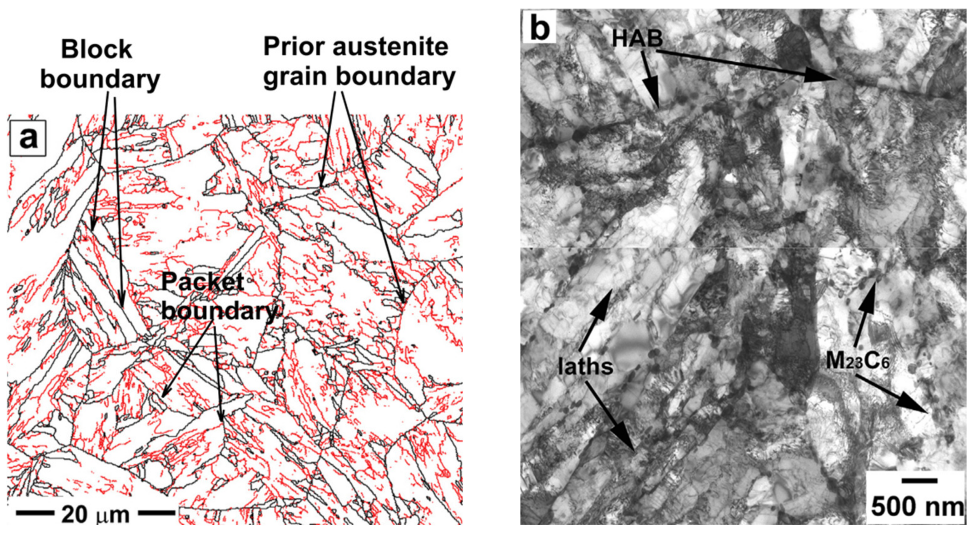
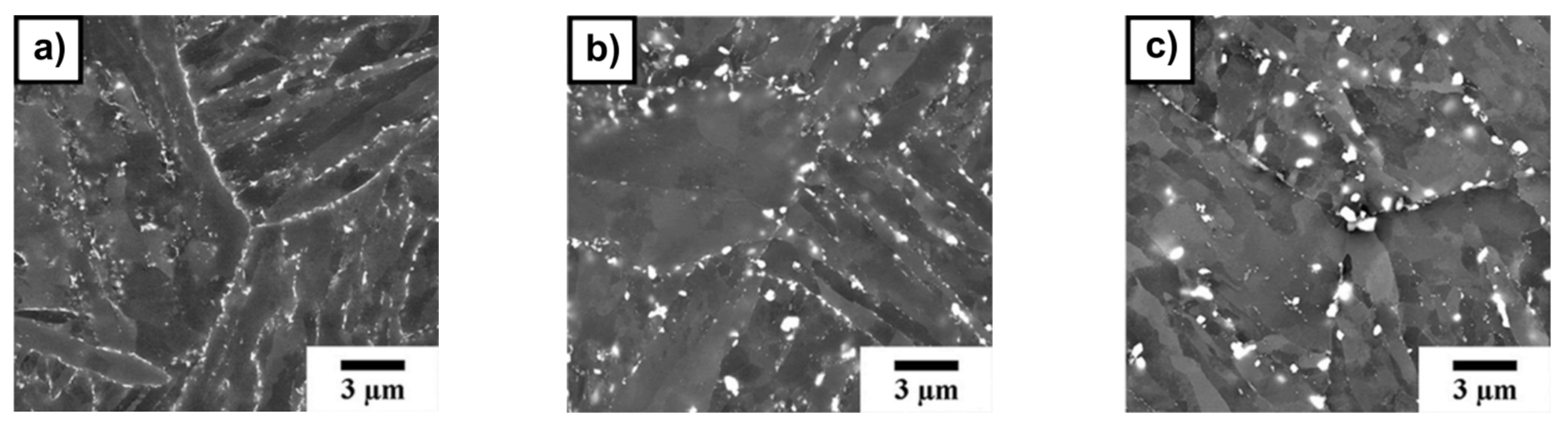
The creep resistance of high-chromium martensitic steels is determined by the stability of the non-equilibrium hierarchical microstructure. Prior austenite grains (PAG), packets, and blocks with martensite laths are the structural elements of the typical martensite lath structure [7,8] (Figure 1). Two main dispersion strengthening phases are the nanoscale M23C6 (where M—Cr, Fe, W, etc.) carbides and the fine MX carbonitrides (where M—V, Nb and X—C, N). During tempering, the M23C6 carbides precipitated on boundaries, while the MX carbonitrides homogeneously precipitated in the lath interiors. Both M23C6 carbides and MX carbonitrides prevent the dislocation climb and slow down the migration of low-angle boundaries through suppressing the knitting reaction between the dislocations comprising lath boundaries and lattice dislocations [9,10]. The transformation of the lath structure into the subgrain structure results in degradation of creep resistance.
One of the most effective ways to enhance the creep resistance was suggested by researchers at the National Institute for Materials Science (NIMS) in Japan. The method consists of increasing the B content and decreasing the N content [11,12,13]. Microalloying by approximately 0.01 wt.% B can increase the long-term creep resistance of the steels [1,7,8,14,15,16,17]. Boron has a positive effect on the coarsening resistance of M23C6–type carbides [7,8,15,18]. A nitrogen removal to approximately 0.01 wt.% prevents the BN formation and can also positively affect the creep resistance [7,8,13,15].
Currently, new 9% Cr steels, as well as 10–12% Cr steels, are being developed using this approach. This paper presents information on the creep resistance of 9–12% Cr steels with increased boron and decreased nitrogen contents. The features of their microstructure and precipitates are considered in detail.
2. Obtaining and Heat Treatment of Steels
2.1. Chemical Composition of Steels
Chemical compositions of considered 9% Cr, 10% Cr, and 11–12% Cr steels with the increased B and decreased N contents are presented in Table 1. Moreover, chemical compositions of other 9–12% Cr steels with conventional B and N contents, used for comparison, are shown in Table 1.
Advanced steels contain 2–3% Co, which is known to have a positive effect on the microstructure and creep strength of high-Cr steels [19,20,21,22,23]. The main purpose of the Co addition is to suppress the formation of undesirable δ-ferrite during normalizing. Helis et al. studied the effect of 0–5% Co on the 9Cr-3W-0.2V-0.05Nb-0.08C-0.05N steel [19]. It was found that addition of 1% Co reduced the δ-ferrite fraction from 6% to 0.4%, while 3% Co completely eliminated the δ-ferrite. This fact is due to Co being an austenite-forming element, and it extends the austenite region on the phase diagram. The absence of δ-ferrite in high-Cr steels increases the stability of the tempered martensite lath structure [19].
On the other hand, although precipitates do not contain Co, the addition of 3% Co provides an increasing amount of MX carbonitrides and M23C6 particles. It was revealed that the number of precipitates around PAG boundaries significantly increased at 3% Co from 6 (at 0% Co) to 14 per μm2 [19]. Co also affects the chemical composition of precipitates, increasing the V content in MX particles, and the Fe, Cr, and W content in M23C6 particles. Therefore, Co indirectly affects the precipitation strengthening of 9–12% Cr steels.
The most advanced steels contain 3%W–0%Mo in order to increase the precipitation strengthening and boundary strengthening. As was shown by Abe [24], the 3W–Mo steel exhibits the longest creep rupture time as compared with 0W–.5Mo and 1.8W-0.6Mo steels. The addition of 3% W was found to be more effective to stabilize the fine distribution of M23C6 carbides along the PAG and packet and lath boundaries than Mo [24]. Therefore, a part or all of Mo is substituted with W in the steels.
2.1.1. The 9% Cr Steels
The 9% Cr steels are represented by the advanced CSEF steels, such as MARBN, G115, and SAVE12AD steels, and experimental 9Cr-1.5W-3Co steel.
The MARBN steel is the Japanese 9% Cr steel developed by National Institute of Materials Science (NIMS), in co-operation with private companies in Japan, for application to thick section boiler components in USC power plant [11,25,26]. MARBN is a MARtensitic 9Cr steel strengthened by B boron and N nitrides [11,25,26]. Various compositions of MARBN steel are presented in literature, differing in concentrations of B and N [11,25,26,27]. In this work, we consider the compositions with 139 ppm B/34 ppm N and 135 ppm B/79 ppm N presented by Abe et al. [11,25,26] and with 100 ppm B/80 ppm N studied by Abstoss et al. [27].
The G115 steel is the 9% Cr Chinese steel developed by the China Iron and Steel Research Institute (CISRI) and Bao Steel [28,29,30]. This 9Cr-3W-3Co-1CuVNbB steel is recommended for use in USC power plants at operation temperatures up to 650 °C in China owing to its excellent overall properties. It is reported that G115 with 2.8%W–3%Co is for piping and with 3% W–3% Co for tubing [30]. Composition of the G115 is similar to MARBN steel, while approximately 1% Cu is added in order for additional strengthening by fine Cu-rich particles, by analogy with P122 steel [6,31]. The G115 steel with 140–150 ppm B/80–90 ppm N is considered in works of Liu et al. [16] and Xiao et al. [32,33].
The SAVE12AD steel is the new 9% Cr steel, additionally alloyed by Nd and Ta, developed by Nippon Steel of Sumitomo Metal Corporation, Japan for large diameter and heavy wall thickness pipes and forgings of fossil-fired power boilers [5,34,35,36]. The SAVE12AD is presented in works of Hamaguchi et al. [34,35]. This steel was designed as an improvement on 11% Cr steel, SAVE12 (0.1C-11Cr-3W-3Co-V-Nb-Ta-Nd-N, in mass %) [37], by decreasing the Cr content from 11 to 9% in order to enhance the long-term creep strength. The steel is alloyed by 0.03 wt.% Nd to improve ductility and suppress creep rupture through suppressing the S segregation [36]. Concentrations of B and N are reported to be 0.01 wt.% B and 0.01 wt.% N, corresponding to the range 70–150 ppm B and 50–150 ppm N [36].
2.1.2. The 10% Cr Steels
The 10% Cr steels are represented by the experimental 10Cr [8,15] and 10Cr-0.2Re [39,40,41] steels designed on the base of TOS 110 steel. As known, TOS 110 steel was developed in Japan at Toshiba with the main composition of 10Cr-0.7Mo-1.8W-3Co-VNb-0.01B-0.02N for turbine rotor application at 630 °C [42,43,44]. The experimental 10Cr steel is a modification of TOS 110 steel by decreasing the N content to 0.003% and addition of Ti (0.002%) while maintaining the high B content of 0.008%. It was shown that this modification results in enhanced long-term creep rupture strength [8,15]. The NF12 [2] and HR1200 [43,45] steels were used for comparison of creep resistance of the 10Cr steel.
The 10Cr-0.2Re steel was designed on the base of the following approaches: (1) the most part of Mo is replaced by W for increasing the precipitation strengthening (2.86% W–0.13% Mo); (2) rhenium is added (0.2% Re) to improve creep strength as it was found that Re not only increases the solid solution strengthening but also has a retardation effect on the W diffusion [39,40,41]. TOS 203 steel with 0.2% Re [46] was used for comparison of creep strength of the 10Cr-0.2Re steel.
2.1.3. The 11–12% Cr Steels
The 11–12% Cr steels are represented by the TAF650, SuperVM12 steels, and experimental 12% Cr steels.
The TAF650 steel is the 12% Cr Japanese steel derived from the TAF steel [47]. The TAF steel was developed in 1956 by Toshio Fujita [48] and has the superior high temperature strength. The TAF650 steel was developed for improvement of poor weldability and hot workability. In the TAF650 steel, the part of Mo was replaced by W; Co and Ni were added; C and B contents were reduced from 0.21% to 0.1% and from 0.03% to 0.019%, respectively (Table 1) [49,50,51,52].
The SuperVM12 steel is a new 12% Cr ferritic martensitic steel developed by Vallourec Group [53,54]. The SuperVM12 steel combines excellent creep rupture strength properties and enhanced steam oxidation resistance of 12% Cr steels, such as VM12-SHC [55]. Oxidation rates of the SuperVM12 steel are significantly smaller than those of 9% Cr steels, such as P92 and MARBN [54].
The experimental 12% Cr and 12% Cr-Ta steels were developed and studied by Fedoseeva et al. [17,56]. The 12% Cr and 12% Cr-Ta steels contain 3.9% and 3% Co, respectively, in order to prevent formation of δ-ferrite and increase the precipitation strengthening. Moreover, these 12%Cr steels are alloyed by 0.8% Cu and 0.07% Ta as austenite-stabilizing elements [17,56]. Concentrations of B and N are 0.008% and 0.003%, respectively.
For comparison of creep strength of 11–12% Cr steels, the 12Cr steel studied by Yadav et al. with conventional B and N was also used [57,58].

Table 1.
Chemical composition of 9–12% Cr steels with high B and low N contents (in wt. %). Data are adapted from Refs. [2,5,6,8,11,15,16,17,18,20,21,22,25,26,27,31,32,33,34,35,36,37,38,39,41,42,43,44,45,46,49,50,51,52,53,54,55,56,57,58].
| Steel | Fe | C | Cr | Co | W | Mo | Si | Mn | Ni | V | Nb | N | B | Others | Heat Treatment *, °C | d PAG, μm | Ref. |
|---|---|---|---|---|---|---|---|---|---|---|---|---|---|---|---|---|---|
| 9% Cr | |||||||||||||||||
| MARBN (Abe) | bal. | 0.08 | 8.88 | 3.00 | 2.85 | - | 0.31 | 0.49 | - | 0.19 | 0.05 | 0.0079 | 0.0135 | - | N 1150, 1 h T 770, 4 h | [11,25,26] | |
| bal. | 0.08 | 8.99 | 3.01 | 2.91 | - | 0.30 | 0.51 | - | 0.19 | 0.05 | 0.0034 | 0.0139 | - | N 1080, 1 h T 800, 1 h | 60 | [11,25,26] | |
| MARBN (Abstoss) | bal. | 0.08 | 9.26 | 2.97 | 2.87 | - | 0.32 | 0.52 | - | 0.157 | 0.055 | 0.008 | 0.01 | - | N 1150, 1 h T 770, 4 h | - | [27] |
| G115 (Liu) | bal. | 0.082 | 8.96 | 3 | 2.62 | - | 0.34 | 0.53 | - | 0.2 | 0.05 | 0.009 | 0.015 | 0.94 Cu | N 1100, 1 h T 780, 3 h | - | [16] |
| G115 (Xiao) | bal. | 0.08 | 8.8 | 3 | 2.8 | - | 0.3 | 0.5 | - | 0.2 | 0.06 | 0.008 | 0.014 | 1.0 Cu | N 1100, 1 h T 760, 3 h | ~100 | [32,33] |
| SAVE12AD | bal. | 0.05–0.1 | 8.5–9.5 | 2.5–3.5 | 2.5–3.5 | - | 0.05–0.5 | 0.2–0.7 | <0.2 | 0.15–0.3 | Nb + Ta 0.05–0.12 | 0.005–0.015 | 0.007–0.015 | 0.01–0.06 Nd | N 1070–1170 T 750–790 | 150–200 | [5,34,35] |
| 9Cr-1.5W-3Co | bal. | 0.095 | 9.05 | 2.86 | 1.56 | 0.58 | 0.12 | 0.41 | 0.24 | 0.20 | 0.05 | 0.007 | 0.0120 | 0.03 Cu | N 1060, 1 h T 750, 3 h | 26 | [18,38] |
| Reference 9% Cr steels with conventional B and N contents | |||||||||||||||||
| P92 | bal. | 0.07–0.13 | 8.5–9.5 | - | 1.5–2.0 | 0.3–0.6 | <0.5 | <0.6 | <0.4 | 0.15–0.25 | 0.04–0.09 | 0.03–0.07 | 0.001–0.006 | - | [6] | ||
| 9Cr-2W-3Co | bal. | 0.120 | 9.50 | 3.10 | 2.00 | 0.44 | 0.08 | 0.2 | 0.04 | 0.20 | 0.06 | 0.050 | 0.0050 | 0.08 Cu | N 1050, 1 h T 750, 3 h | 10 | [20,21] |
| 9Cr-3W-3Co | bal. | 0.120 | 9.40 | 3.10 | 3.00 | 0.44 | 0.08 | 0.2 | 0.04 | 0.2 | 0.06 | 0.050 | 0.0050 | 0.08 Cu | N 1050, 1 h T 750, 3 h | 20 | [22] |
| 10% Cr | |||||||||||||||||
| 10Cr | bal. | 0.10 | 10.0 | 3.00 | 2.00 | 0.70 | 0.06 | 0.10 | 0.17 | 0.20 | 0.05 | 0.003 | 0.0080 | 0.006 Cu <0.002 Ti | N 1060, 1 h T 770, 3 h | 35 | [8,15] |
| 10Cr-0.2Re | bal. | 0.11 | 9.85 | 3.2 | 2.86 | 0.13 | 0.03 | 0.14 | 0.03 | 0.23 | 0.07 | 0.002 | 0.008 | 0.17 Re 0.22 Cu | N 1050, 1 h T 770, 3 h | 55 | [39,40,41] |
| Reference 10% Cr steels with conventional B and N contents | |||||||||||||||||
| NF12 | bal. | 0.1 | 10.2 | 2.0 | 2.5 | 0.15 | 0.35 | 0.5 | 0.1 | 0.22 | 0.07 | 0.02 | 0.005 | - | - | - | [2] |
| TOS 110 | bal. | 0.11 | 10.0 | 3.00 | 1.8 | 0.65 | 0.08 | 0.10 | 0.2 | 0.20 | 0.05 | 0.02 | 0.01 | - | - | [42,43,44] | |
| HR1200 | bal. | 0.1 | 11.0 | 2.7 | 2.7 | 0.23 | 0.06 | 0.55 | 0.5 | 0.22 | 0.07 | 0.02 | 0.02 | - | - | - | [43,45] |
| TOS 203 | bal. | 0.1 | 10.5 | 1.0 | 2.5 | 0.1 | 0.07 | 0.5 | 0.6 | 0.2 | 0.08 | 0.04 | 0.015 | 0.2 Re | N 1120, 3 h (oil) T 680, 5 h + 650,5 h | ~100 | [46] |
| Steel | Fe | C | Cr | Co | W | Mo | Si | Mn | Ni | V | Nb | N | B | others | Heat treatment *, °C | dPAG, μm | Ref. |
| 11–12% Cr | |||||||||||||||||
| SuperVM12 | bal. | 0.1–0.16 | 11 | 1.8 | 2 | 0.5 | 0.5 | 0.3–0.8 | <0.4 | 0.15–0.3 | 0.02–0.1 | 0.011 | 0.014 | - | N 1100, 0.5 h T 780, 2 h | ~200 | [53,54] |
| TAF650 (Sawada) | bal. | 0.11 | 10.99 | 2.9 | 2.59 | 0.15 | 0.04 | 0.43 | 0.52 | 0.19 | 0.07 | 0.02 | 0.017 | - | N 1100, 1 h (oil) T 680, 3 h | 33 | [49] |
| TAF650 (Svoboda) | bal. | 0.1 | 10.84 | 2.86 | 2.63 | 0.14 | 0.07 | 0.55 | 0.55 | 0.19 | 0.06 | 0.016 | 0.019 | - | N 1100, 1 h (oil) T 750, 2 h | [50,51,52] | |
| 12% Cr (Fedoseeva) | bal. | 0.09 | 11.3 | 3.9 | 2.4 | 0.63 | - | - | - | 0.24 | 0.07 | 0.003 | 0.009 | 0.78 Cu | N 1050–1070, 1 h T 750–770, 3 h | 51 | [17] |
| 12% Cr–Ta (Fedoseeva) | bal. | 0.11 | 11.4 | 3.0 | 2.5 | 0.62 | 0.02 | 0.04 | 0.03 | 0.23 | 0.04 | 0.003 | 0.01 | 0.76 Cu 0.07 Ta | 48 | [17,56] | |
| Reference 11–12% Cr steels with conventional B and N contents | |||||||||||||||||
| P122 | bal. | 0.07–0.14 | 10–11.5 | - | 1.5–2.5 | 0.25–0.6 | <0.5 | <0.7 | <0.5 | 0.15–0.3 | 0.04–0.1 | 0.04–0.1 | 0.0005–0.005 | 0.3–1.7 Cu | - | [6,31] | |
| VM12-SHC | bal. | 0.1–0.14 | 11 | 1.6 | 1.5 | 0.3 | 0.5 | 0.15–0.45 | <0.4 | 0.2–0.3 | 0.03–0.08 | 0.06 | 0.005 | - | N 1060, 0.5 h T 780, 2 h | [54,55] | |
| TAF | bal. | 0.1 | 10.53 | - | - | 1.59 | 0.41 | 0.89 | - | 0.2 | 0.2 | 0.02 | 0.037 | - | - | [51] | |
| Save12 | bal. | 0.1 | 11 | 3.0 | 3.0 | - | 0.3 | 0.2 | - | 0.2 | 0.07 | 0.04 | 0.006 | 0.04 Nd 0.07 Ta | - | [37] | |
| 12Cr (Yadav) | bal. | 0.06 | 12.1 | 3.5 | 2.47 | 0.01 | 0.31 | 0.21 | 0.19 | - | - | 0.06 | 0.006 | 1.95 Cu 0.36 Ta | N 1150, 1 h T 650, 6 h +740, 6 h | [57,58] | |
* N—normalization, T—tempering.
2.2. Vacuum Induction Melting of Steels
In contrast to high-chromium steels with conventional N content (~0.05%), the method of vacuum induction melting is used for producing steels with decreased nitrogen content (<0.01%). It is attributed to the fact that the nitrogen content in alloy is determined by the gas pressure on the molten alloy.
As is known, the solubility of the diatomic nitrogen gas (N2) in metal melt can be described by the reaction:
and obeys Sievert’s law [59], according to which the solubility of nitrogen gas in metal melts is proportional to the square root of the partial pressure of the gas (under constant temperature):
where [N] is the solubility of the nitrogen gas in metal melt at a given partial pressure of gas pN2; KN is the solubility constant (Sievert’s constant), which depends on temperature and the way concentration and pressure are expressed.
1/2 N2 = [N],
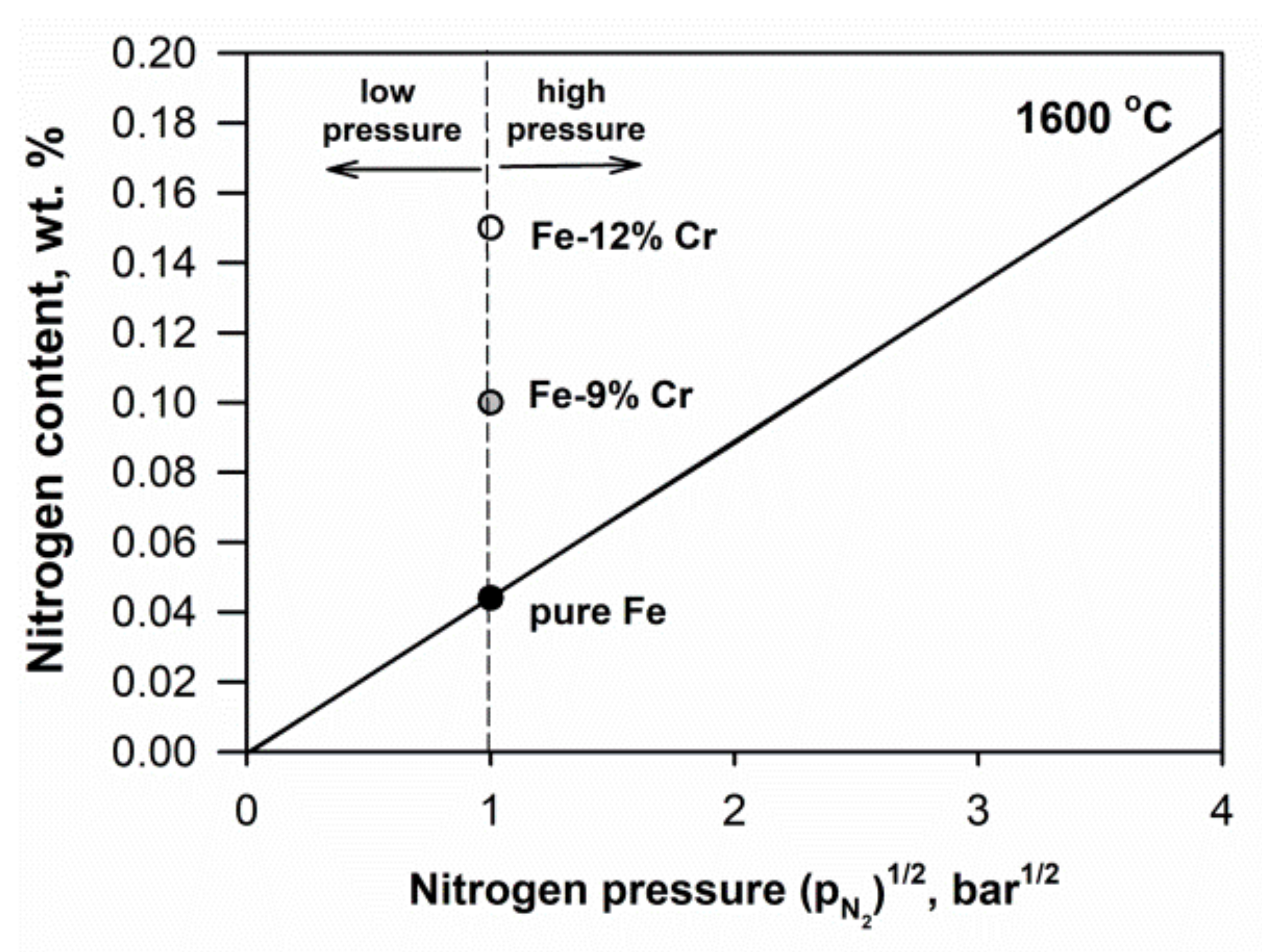
Figure 2 presents the effect of nitrogen partial pressure on the nitrogen content in a liquid pure iron at 1600 °C [60]. It is seen that the solubility of nitrogen in pure Fe is approximately 0.044 wt. % at 1 bar. Alloying elements also affect the solubility of nitrogen. Nitride-forming elements, such as Cr, V, and Al, increase the solubility of nitrogen. Thus, in liquid Fe alloy with 9 and 12% Cr at atmospheric pressure of ~1 bar, the soluble nitrogen content is significantly higher (0.1% and 0.15%, respectively) than in pure Fe.
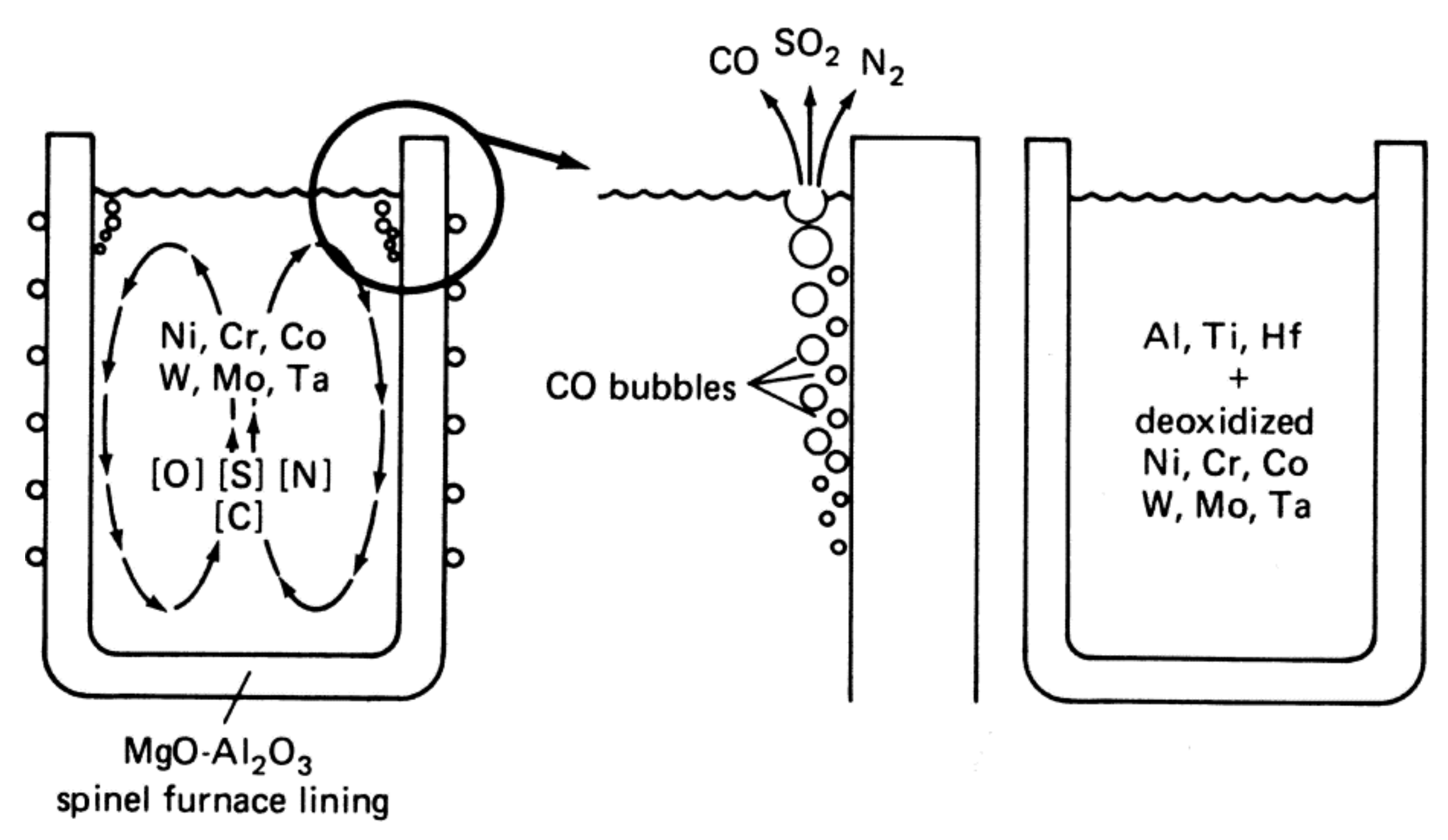
Excess nitrogen content can be removed from molten steels according to Sievert’s law with vacuum. During vacuum induction melting, when vacuum and stirring are applied, dissolved nitrogen is adsorbed by bubbles and is flushed from the melt (Figure 3) [61]. Depending on required N content in steel, the pressure is varied.
2.3. Heat Treatment
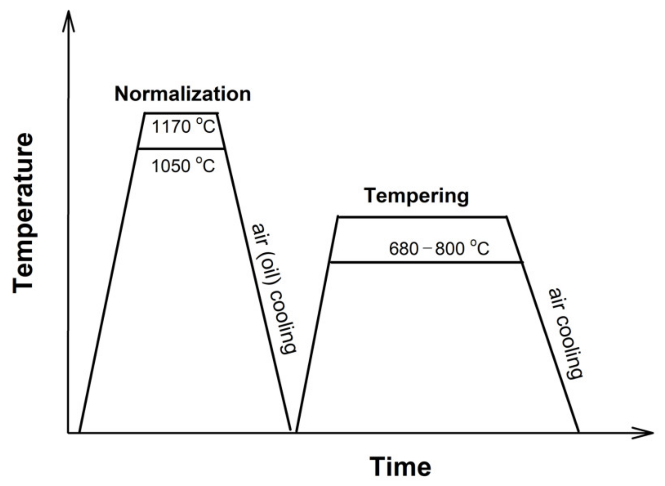
Heat treatment of the steels usually consists in normalization and tempering in order to form a tempered martensite lath structure. Normalization of the considered steels is carried out in a wide temperature range of 1050 to 1170 °C (Table 1, Figure 4). Heating is carried out in the austenite region for preventing the δ-ferrite formation after normalization. Duration of heating varies from 0.5 to 1 h. During cooling (by air or oil), the austenite transforms to martensite. The normalization leads to the formation of the lath martensite structure, in which the PAGs, packets, blocks, and laths with high density of lattice dislocations are distinguished. The normalization temperature affects the PAG size. The size of PAG in the steels significantly varies from 20 to 200 μm due to different normalization temperatures (Table 1).
Typical tempering temperatures are 750–780 °C, although lower and higher temperatures in the range of 680–800 °C are encountered. Duration of tempering varies in the range 1–4 h. During tempering, the normalized martensite becomes tempered martensite and the tempered martensite lath structure is formed (Figure 1). The dislocation density decreases as compared to the normalized state but remains high, approximately 2–4 × 10¹⁴ m−2. The M23C6 carbides precipitate on boundaries of PAGs, packets, blocks, and laths, while the MX carbonitrides homogeneously precipitate in the lath interiors.
3. The Boron/Nitrogen Ratio in the Steels
Boron is known to improve the stability of tempered martensite lath structure through the stability of M23C6 carbides. Boron suppresses the coarsening of these carbides. As it is included in M23(B, C)6 carbides during tempering, it significantly reduces the diffusion processes and retains the fine carbides for a long time [7,14].
However, addition of B alone to the steels can have a negative effect. Thus, El-Kashif et al. [62] reported that, at conventional N content (0.05 wt.%), increasing B from conventional 0.001% to 0.006% in the 9Cr-3W-3Co steel reduced the time to rupture by two times at creep testing at 650 °C, 160 MPa. The change in B content was accompanied by a decrease in the PAG size from 160 to 120 μm. At the same time, when the N content was lower than conventional and comprised 0.02%, an increase in the B content to 0.01 wt. % increased time to rupture. It is interesting, that creep strength improved in this case despite the fact that the PAG size also decreased from 155 to 110 μm. Then, this change in the PAG size did not affect the creep resistance. In the high N–high B steel, the number density of precipitates containing B was the highest, whereas, in the low N–high B steel, more free B existed in the matrix [62]. Therefore, free B in solid solution is more effective on the stabilization of the microstructure and strengthening than B contained in precipitates [62].
Therefore, the B/N ratio should be controlled to increase the operating temperature. The following factors determine the contents of boron and nitrogen:
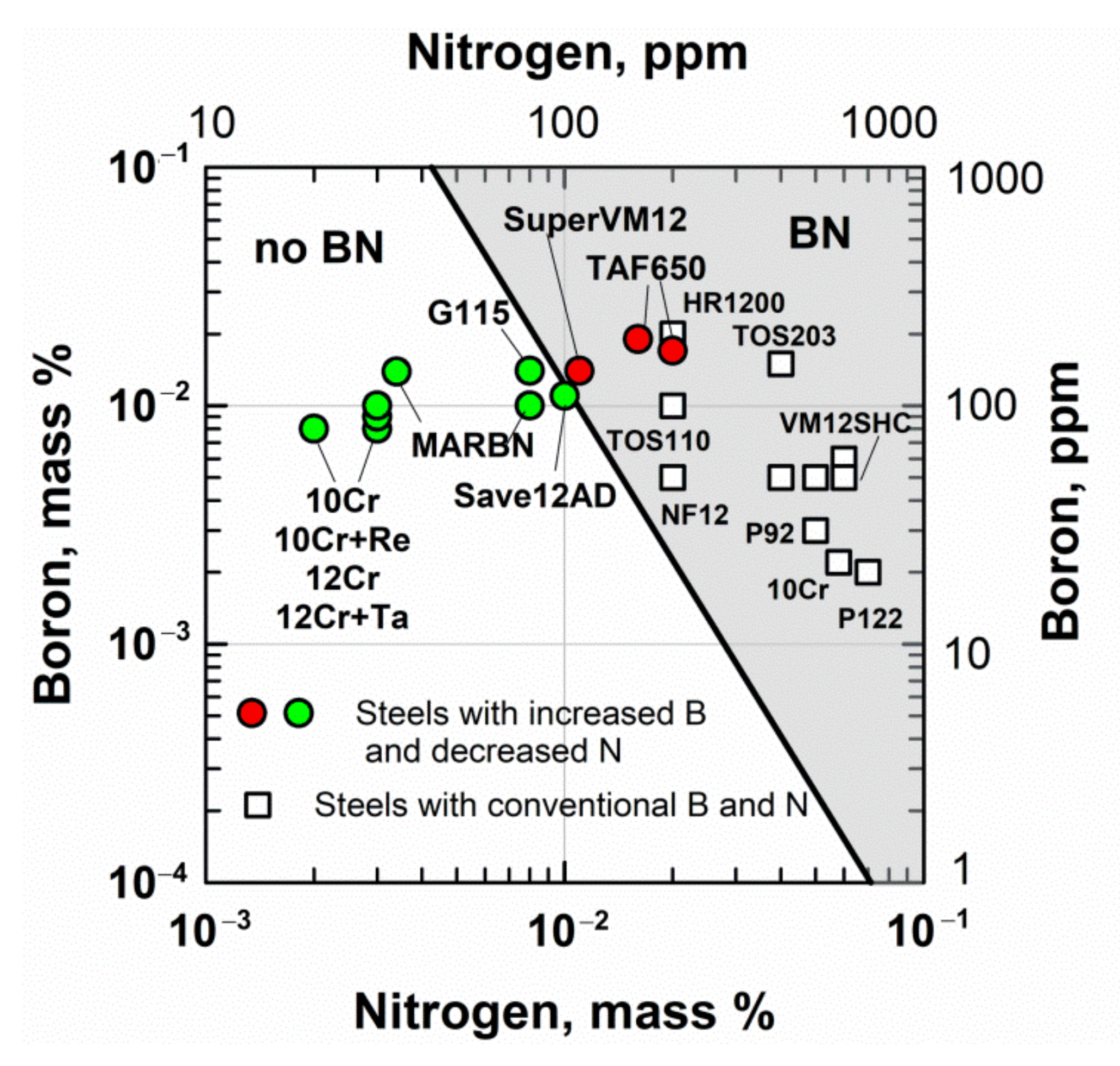
- Preventing the formation of BN phase. On the one hand, an increased boron content enhances the coarsening resistance of M23C6-type carbides during creep. On the other hand, the presence and content of nitrogen strongly affects the efficiency of alloying with boron. Nitrogen affects the solubility of boron in the ferritic matrix. At excess nitrogen content, the undesirable BN phase is formed during normalization. The coarse BN precipitates can act as initiation sites for creep cavities that reduce the creep resistance and creep ductility. Formation of BN leads to a depletion of boron from the ferritic matrix.
The solubility of boron is determined by the solubility product for boron nitride in 9–12% Cr steels at a normalizing temperature of 1050–1150 °C, given by [63]:
where [%B] and [%N] are the concentration of soluble boron and soluble nitrogen in mass %, respectively.
log[%B] = −2.45 log [%N] − 6.81,
Figure 5 shows the border between the B and N concentration regions with BN and without BN in the solid solution in 9–12%Cr steels at a normalizing temperature of 1050–1150 °C [7,24]. Most of the considered steels with increased B and decreased N contents are free from BN according to this diagram. The high B content in the range of 0.007 to 0.02% is compensated by the low N content of less than approximately 0.01%. This allows all the added boron to be dissolved in the matrix or M23C6 without formation of BN after normalization. The exception is the TAF650 steel [49,50,51], in which the N content of 0.016% is about twice higher than the soluble limit of 0.0084% N at the B content of 0.019%. Moreover, in the SuperVM12 steel, 0.011% N and 0.014% B can result in BN appearance.
The steels with conventional B and N contents, such as P92, P122, Save12, NF12, and others, are prone to BN formation. Therefore, in these steels, the soluble B content is low due to the fact that B is consumed to form the BN. Sakuraya et al. [63] showed that there are many BN type inclusions with sizes up to about 4 μm in the P122 and P92 steels. Moreover, in the P122 steel, the BN inclusions were revealed to agglomerate in large size colonies (20 μm).
BN particles reduce creep ductility that deteriorates creep strength at long times [64]. Abe et al. established that the BN particles are responsible for the degradation in reduction of area (RA) at low stresses and long times by accelerating the formation of creep voids at interfaces between the BN particles and alloy matrix [65]. As is known, this process occurs at the late stage of tertiary creep stage. On the other hand, the BN particles have no negative effect on the creep rupture time in the steels with balanced content of W-Mo. Thus, the 9% Cr-3W-0Mo-0.0049N-0.0031B steel with the W-Mo balance parameter 1/2W/(1/2W + Mo) = 1 exhibited the same creep life as 9Cr-0.0092B-0.0016N steel despite the presence of BN precipitates [65].
Along with BN, the AlN particles are responsible for the degradation in RA at low stresses and long times. Abe et al. showed that, in 12Cr-1Mo-1W-0.3V steel, the dissolved nitrogen and fine vanadium nitrides are gradually consumed by the formation of AlN and TiN during creep [65]. This leads to reducing the both creep rupture time and creep ductility.
- 2.
- Optimal fraction of MX phase. The nitrogen content determines the volume fraction of MX carbonitrides, namely N- and V-enriched precipitates, in steels. At optimal B content, the N content should not be too high or too low.
Thus, in the MARBN steel (9Cr-3W-3Co) with 140 ppm B, Abe et al. showed that 79 ppm N improved the creep rupture time as compared with conventional 650 ppm N, whereas the low N content of 15 and 34 ppm reduces creep rupture time (Figure 6) [11,26]. According to Equation (3), at 140 ppm B, 95 ppm N can dissolve in the matrix without any formation of BN during normalization. However, low N results in a low fraction of MX phase. Therefore, weak strengthening by MX carbonitrides results in a higher minimum creep rate and shorter time to rupture. It is interesting that, at 79 ppm N, most of the N dissolved in the matrix after tempering and then started to precipitate in very fine MX carbonitrides during 1000 h of creep, which contributed to the creep strength [11].
The same results were obtained in the P91 steel with 100 ppm B, where too-low N content of 20 ppm reduced the creep resistance due to low fraction of MX phase [66]. Creep rupture time of P91–100 ppm B-20 ppm N was 296 h, whereas that of P91–90 ppm B—90 ppm N was 544 h at 120 MPa, 650 °C [66]. Rejeesh et al. recommended the optimal ratio of 70–100 ppm B and 90–100 ppm N for modified 9Cr-1Mo steel [66]. Their experimental results showed that the maximum creep rupture time of steel with the B/N ratio of 70 ppm/108 ppm is associated with the maximum MX fraction of 0.0017%, whereas a lower N of 20 ppm reduces it by two times (Table 2). It is interesting that, at this optimal B/N ratio (70 ppm/108 ppm), the highest volume fraction of Σ(M23C6 + M23(B,C)6) phases of 0.031% was predicted by Thermo-Calc.
- 3.
- Preventing MX→Z-phase transformation. In the steels with 10–12% Cr, a low N concentration prevents the transformation of the MX phase into the undesirable coarse Z-phase particles (CrVN). Thus, in the experimental 12% Cr steels with 20 ppm N, the Z phase was not observed even after long-term creep for >20,000 h at 650 °C [17]. In the Super VM12 steel with 110 ppm N, the Z-phase was not revealed after long-term creep during 23,844 h at 650 °C [54].
4. Microstructure and Creep Properties of Advanced 9–12% Cr Steels
4.1. Creep Properties of the 9–12% Cr Steels
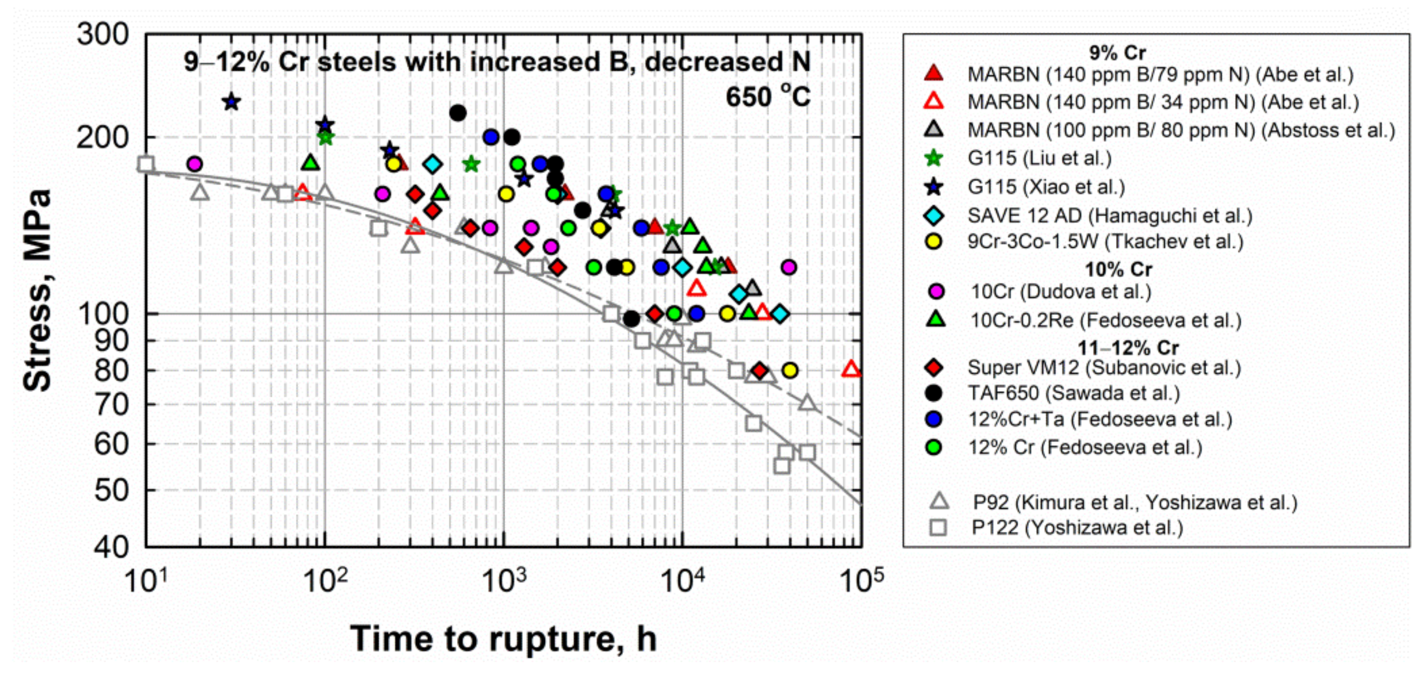
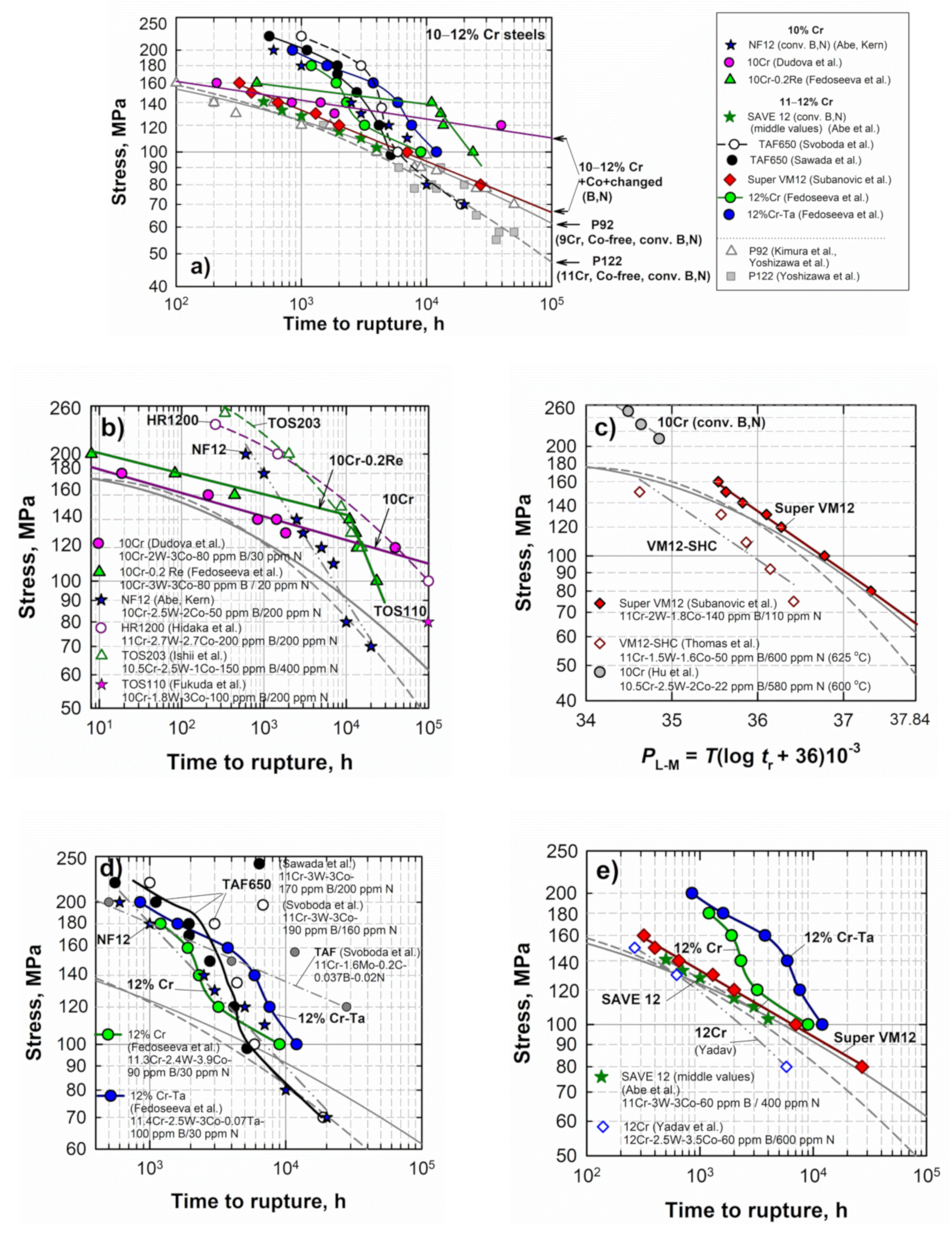
Figure 7 illustrates the creep data at 650 °C for the advanced 9–12% Cr steels with the increased B and decreased N contents in comparison with those for the conventional P92 and P122 steels. The data are from Refs. [5,6,8,11,16,18,20,22,25,27,32,39]. It is clearly seen that the time to rupture versus applied stress points for these steels are higher, mainly than those for the P92 and P122 steels, suggesting the higher creep resistance of new steels.
4.2. The 9% Cr Steels
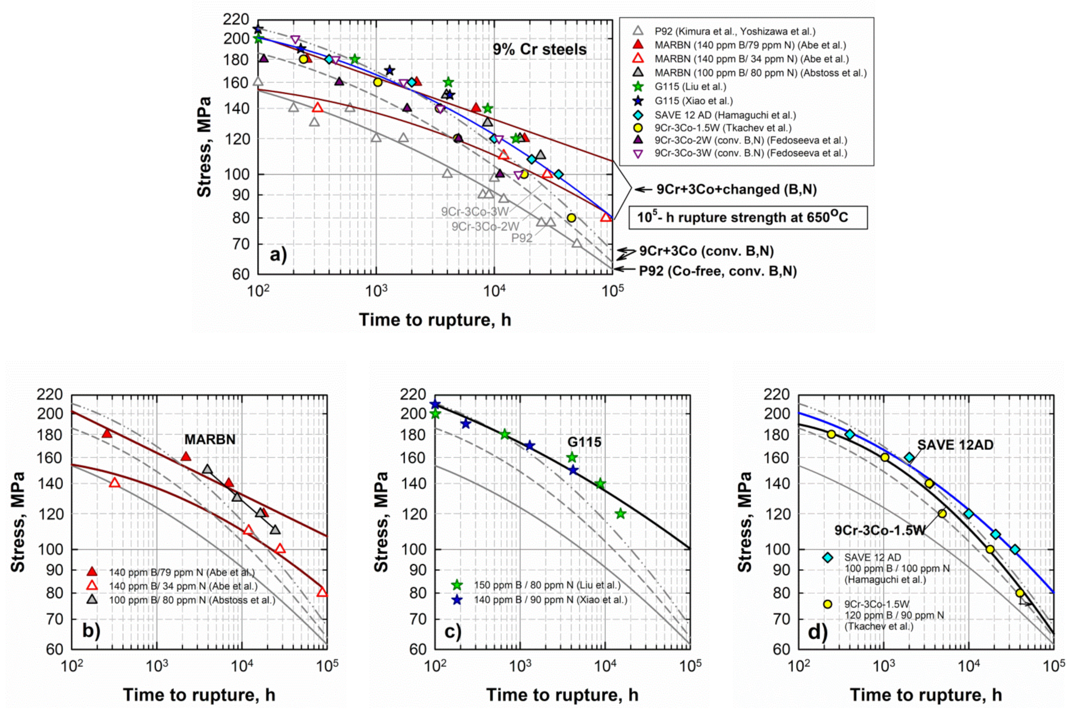
The advanced 9% Cr CSEF steels—the MARBN, G115, and SAVE12AD steels—demonstrate a high level of creep strength both at high stresses (in the short-term creep region) and at low stresses (in the long-term creep region) as compared with the conventional P92 steel (Figure 8). Regression lines of the experimental creep points predict the long-term creep rupture strength of these steels at 650 °C for 100,000 h in the range from 80 to 110 MPa [5]. These values are significantly higher than those for the P92 steel and 3%Co-modified P92 steels with 2% and 3%W (approximately 60–70 MPa) (Figure 8a).
The creep strength curves for the MARBN steel vary depending on the B and N content [11,25]. The MARBN steel with 140 ppm B/79 ppm N demonstrates the highest creep resistance, whereas a lower N content of 34 ppm reduces the creep strength (Figure 8b).
The G115 steels with slightly different B and N content (140–150 ppm B and 80–90 ppm N) studied by Liu et al. [16] and Xiao et al. [32,33] exhibit close stress/time to rupture points, which are approximated by a regression line predicting the long-term creep strength of 100 MPa (Figure 8c).
The SAVE12AD steel is predicted to have the long-term creep rupture strength of 80 MPa at 650 °C for 100,000 h (Figure 8d) [36].
The data for the experimental 9Cr-3Co-1.5W steel with 120 ppm B/90 ppm N are located close to those for the G115 and SAVE12AD steels at high stresses; however, the creep strength breakdown took place after 3000 h of creep [18,38], which led to reducing the creep strength at low stresses close to the level of the Co-modified P92 steels (Figure 8d).
4.2.1. MARBN
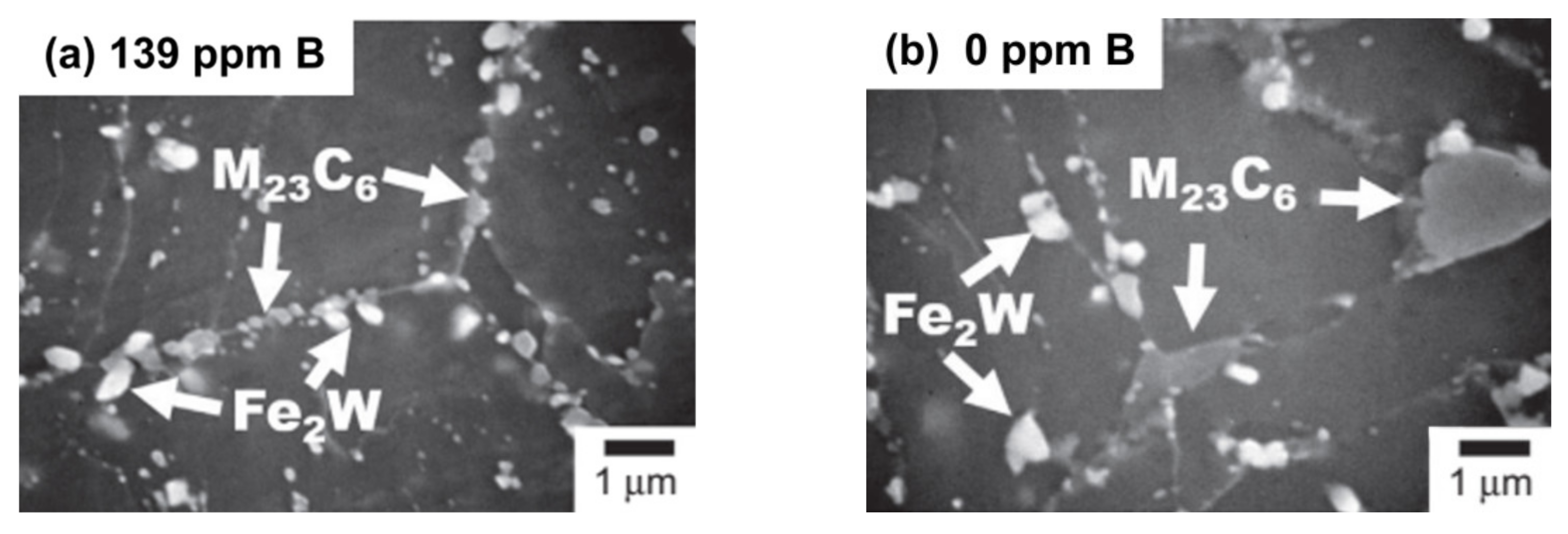
Abe showed that high creep resistance of the MARBN-type steels is associated with B effect on the coarsening resistance of M23C6 carbides, which are located in the vicinity of PAG boundaries [7,67]. Thus, in as-tempered steel, the small M23C6 carbides precipitate both in steel containing B and without B. However, during long-term creep or aging, the fine distribution of M23C6 carbides along PAG boundaries is maintained in the 9Cr steel with 139 ppm B (Figure 9a), whereas individual coarse (more than 1 μm) carbides form in steel without B due to intensive Ostwald ripening (Figure 9b) [7]; i.e., the addition of B reduces the rate of Ostwald ripening of M23C6 carbides in the vicinity of PAG boundaries during exposure at elevated temperature.
The stability of M23C6 carbides in the MARBN steel with 100 ppm B/80 ppm N was shown also in the work of Abstoss et al. [27]. The fine dispersion of M23C6 carbides was observed during creep for 3937 to 16,479 h while decreasing the mean size from 207 to 183 nm, increasing the number density at the increased area fraction of precipitates (Table 3). Their coarsening was observed only after long-term creep at 110 MPa for 24,606 h. Laves phase particles were detected in the vicinity of M23C6 carbides and have a lower number density at a larger mean diameter.
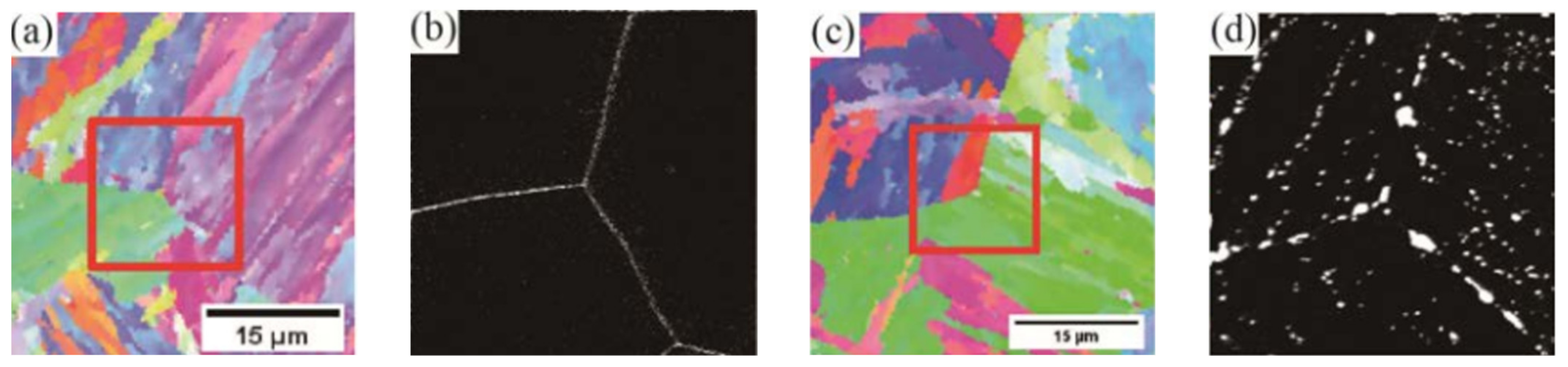
Sekido et al., recently studied the distribution of boron in the MARBN steel with 139 ppm B using nanoscale secondary ion mass spectrometry (Nano-SIMS) [68]. It was revealed that, after normalization from 1100 °C, B segregates on the PAG boundaries only, not on the packet and block boundaries (Figure 10a,b). Therefore, those carbides that precipitate at the PAG boundaries during tempering are enriched in B. After long-term creep (15,426 h), B was found dissolved in M23C6 carbides located on the PAG and block boundaries (Figure 10c,d).
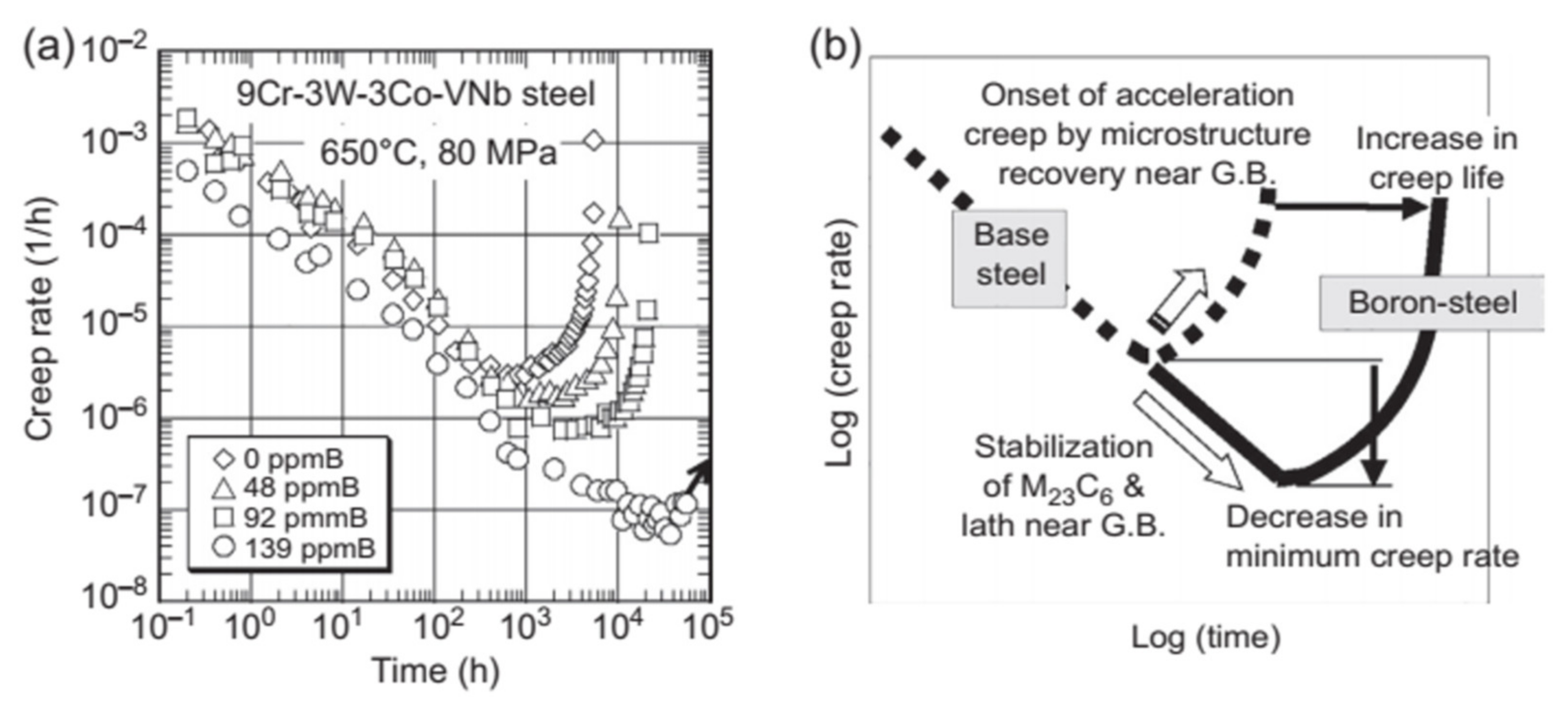
Despite the fact that carbides on PAG boundaries are larger than on the lath boundaries (120 nm and 70 nm, respectively), they are stable during creep. Therefore, these carbides are able to retard the recovery near the PAG boundaries and, hence, prevent the localized creep deformation. Abe found that enrichment of B retards the onset of acceleration creep and extends the transient creep stage to longer times at low stresses. This leads to a lower minimum creep rate and, consequently, to a longer time to rupture (Figure 11) [7,67]. It is illustrated in Figure 11a that, with an increase in the B content from 0 to 92 ppm, the minimum creep rate slightly decreases at 650 °C, 80 MPa, whereas the following increase of B to 139 ppm results in a more than one order of magnitude drop in the minimum creep rate and significantly longer rupture time [7].
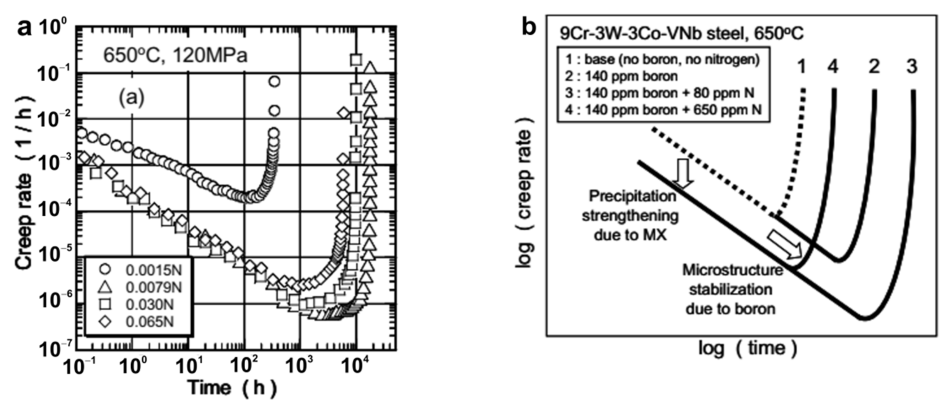
On the other hand, as was mentioned in paragraph 3, in the MARBN steel with 140 ppm B and 79 ppm N, precipitation of very fine (~10 nm) MX particles occurs during 1000 h of creep [11]. This leads to additional precipitation strengthening and enhancement in the creep strength as compared to the steel with lower N content (Figure 6a) [11]. As is presented by Abe [13], additional MX precipitation decreases the creep rates in the transient region, and it also retards the onset of acceleration creep by the microstructure stabilization due to boron (Figure 12). Therefore, that is why the MARBN steel with 140 ppm B/79 ppm N presented by Abe [11] and the MARBN steel with 100 ppm B/80 ppm N presented by Abstoss [27] demonstrate the highest creep resistance, whereas the MARBN steel with a lower N content of 34 ppm shows a lower creep strength curve (Figure 8b).
As was suggested in Ref. [69], the precipitation of small MX particles during the transient creep stage can be the dynamic precipitation. Thus, Lundin et al. suggested that the high creep properties of the 10% Cr steel at 600 °C for up to 10,000 h can be explained by a latent creep resistance, where precipitation processes occur successively during creep in a dynamic process [69]. The presence of very small precipitates, rich in chromium, vanadium, iron, and nitrogen, were revealed by means of atom probe analysis. During dynamic precipitation, a balance between nucleation of very small precipitates on dislocations and their dissolution, when the dislocation manages to break away, is suggested. This process can be repeated, and it should lead to a decrease in the creep rate during steady state creep.
4.2.2. G115 Steel
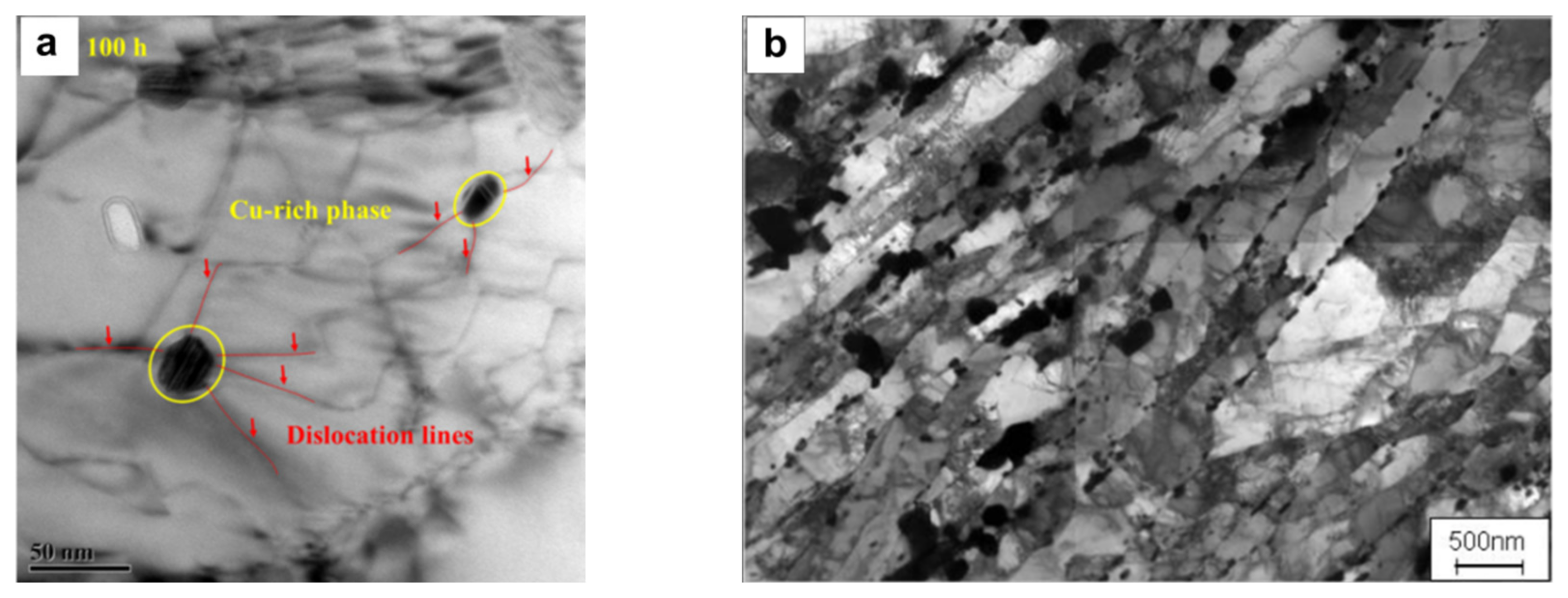
The G115 steel with 140–150 ppm B/80–90 ppm N and additionally alloyed by 1% Cu was studied by Liu et al. [16] and Xiao et al. [32,33]. In the G115 steel, besides the main strengthening phases of M23C6 and MX, fine Cu-rich precipitates nucleate during short-term creep. Cu-rich precipitates were revealed to slightly grow during creep from 35 to 50 nm and then dissolve between 3000 and 4000 h of creep due to their cutting by moving dislocations [32,33]. Therefore, the Cu-rich phase has a significant pinning effect on the dislocations (Figure 13a) and on the stability of martensite structure in the short-term creep region, while, after a creep time of ~1000 h, little strengthening occurs. M23C6 carbides continuously grew up to ~120–150 nm during ~4000 of creep, and then the rapid coarsening to ~200–300 nm took place during long-term creep for 9000–15,000 h [16]. Laves phase particles continuously grew, attaining sizes of ~300 nm during long-term creep. Dislocation density remains high in G115 during both short-term and long-term creep. MX carbonitrides were reported to be enriched by Nb and be very stable under creep conditions, with a size of 35–50 nm [32].
4.2.3. SAVE12AD Steel
The SAVE12AD steel is alloyed by ~0.03 wt.% Nd; the concentrations of B and N are approximately 100 ppm B and 100 ppm N, corresponding to the specified ranges 70–150 ppm B and 50–150 ppm N [36]. Hamaguchi et al., reported that, after creep testing at 650 °C, 108 MPa for 20,687 h, the lath structure almost remained and M23C6 particles were observed along grain and lath boundaries in the SAVE12AD (Figure 13b) [36].
4.2.4. Experimental 9Cr-3Co-1.5W Steel
Tkachev et al. suggested that high creep resistance of the 9Cr-3Co-1.5W steel with 120 ppm B/90 ppm N in the short-term region is provided by strong M23C6 + Laves phase precipitation strengthening [38]. The chains of carbides and Laves phase particles strengthen the lath boundaries (Figure 14a). After 2000 h of creep, the full dissolution of Laves phase particles on the lath boundaries takes place due to Ostwald ripening (Figure 14b,c). Therefore, the creep strength reduces despite the fact that M23C6 carbides remain stable in size. It was found that Z-phase formed during creep; Z-phase precipitates were revealed after a creep test for 17,863 h. However, due to their small size of approximately 70 nm, Z-phase appearance did not affect the creep strength breakdown [38].
4.3. The 10% Cr and 11–12% Cr Steels
The main problem of the 10–12% Cr steels is a drop in creep resistance in the long-term creep region. Creep degradation is associated with the instability of the tempered martensite lath structure under creep conditions, which can be caused by such microstructural changes as:
- -
- preferential recovery of martensitic microstructure near the PAG boundaries;
- -
- Z-phase formation and disappearance of MX strengthening precipitates;
- -
- Laves phase formation, etc.
Thus, the creep strength of the 11% Cr conventional P122 steel is the same as that of P92 steel at high stresses, whereas, at low stresses, creep resistance deteriorates (Figure 15a). Therefore, for the developing 11–12% Cr steels with excellent oxidation resistance due to high Cr content, the main task is to reach the creep strength level at least of the conventional 9% Cr P92 steel.
The experimental 10Cr [8] and 10Cr-0.2Re steels [39,40,41] with 80 ppm B/20–30 ppm N, as compared with the 10% Cr NF12 steel (10Cr-2.5W-2Co) with conventional B and N contents, show advantages in the long-term creep region (Figure 15b). These steels exhibit higher creep strength at low stresses (<140 MPa), whereas, at high stresses, new steels are significantly less resistant to creep than the NF12 steel and closer to the creep level of the P92/P122 steels (Figure 15b).
The 10Cr steel does not demonstrate the creep strength breakdown up to approximately 40,000 h, which results in a high predicted long-term creep rupture strength of 110 MPa at 650 °C for 100,000 h [8]. This value is sufficiently higher than that for the TOS 110 steel, which was developed for application at 630 °C, and its long-term creep rupture strength for 100,000 h at 630 °C is 100 MPa and at 650 °C is nearly 80 MPa [70]. It can be concluded that modification of the TOS 110 steel by a decrease in the N content from conventional 200 ppm to 30 ppm resulted in a higher long-term creep strength of the 10Cr steel [8]. Unfortunately, there are no data on the creep strength curve of the TOS 110 steel in the literature. Therefore, the 10Cr steel is also compared with the HR1200 steel (11Cr-2.7W-2.7Co-200 ppm B/200 ppm N), which was developed at the next step for application at 650 °C by increasing the W content to 2.7% and B content to 200 ppm [43,45]. It is shown in Figure 13b that the creep resistance of the 10Cr steel corresponds to that for the HR1200 steel at about 110–120 MPa, whereas, at >120 MPa, the creep strength of the HR1200 is much higher.
The creep strength of the experimental Re-modified 10Cr steel is significantly higher in comparison with the 10Cr steel at ≥140 MPa. Its time to rupture is about five to ten times longer than that of the 10Cr steel (Figure 15b). However, a marked creep strength breakdown takes place at <140 MPa (~10,000 h), leading to a decrease in the long-term creep strength of the 10Cr-0.2Re steel [40,71]. It should be noted that, at low stresses ≤140 MPa, the creep strength curve for the 10Cr-0.2Re steel is almost the same as for the TOS 203 steel. In contrast, the short-term creep strength of the 10Cr-0.2 Re steel is significantly lower as compared with the TOS 203 steel.
The newly developed 11% Cr SuperVM12 steel with 140 ppm B and 110 ppm N is characterized by excellent creep rupture strength [35,54]. It exhibits a linear time to rupture versus applied stress curve at both high and low stresses, even predicting the 100,000 h creep rupture strength of approximately 65 MPa (even slightly higher than for P92 steel) (Figure 15c). Meanwhile, for the previous VM12-SHC steel, the long-term creep rupture strength is predicted to be less than 45 MPa using the Larson–Miller parameter [72] for creep data obtained at 625 °C [73]:
where T is the absolute temperature, tr is the time to rupture.
PLM = T(logtr + 36) × 10−3,
The TAF650 steel (~11% Cr, 170–190 ppm B, 160–200 ppm N) [49,50,51,52] and the 12% Cr and 12% Cr–Ta steels (11.4% Cr, 90–100 ppm B, 30 ppm N) [17,56] demonstrate significantly higher creep strength at high stresses (at ≥ 120 MPa) than the SuperVM12 and SAVE12 steels (Figure 15d). However, at low stresses below 100 MPa, the rupture time becomes the same or lower as for the P92 and Super VM12 steels. The creep strength curve of TAF650 steel can be characterized as sigmoidal-shape. It is interesting that the original TAF steel did not show the sigmoidal curve in contrast to the TAF650 steel [50,51] (Figure 15d).
The creep strength behavior of the 12% Cr steel (11.3Cr-2.4W-3.9Co-90 ppm B/30 ppm N) at high stresses corresponds to that for the TAF650 steel (Figure 15d,e). The addition of Ta improves the creep strength and shifts the curve to higher times to rupture at <160 MPa (Figure 15e) for the 12% Cr–Ta steel (11.4Cr-2.5W-3 Co-0.07Ta-100 ppm B/30 ppm N). It seems that these steels also show the sigmoidal shape of time to rupture versus applied stress curves. As compared to the 12% Cr steels with conventional B and N content, such as SAVE12 (11Cr-3W-3C0–40 ppm B/600 ppm N) [37] and the 12Cr steel studied by Yadav et al. (12Cr-2.5W-3.5Co-2Cu-0.36Ta-60 ppm B/600 ppm N) [57,58], the 12% Cr and 12% Cr–Ta steels demonstrate significantly higher creep strength in the high-stress region (>120 MPa).
4.3.1. Experimental 10Cr Steel
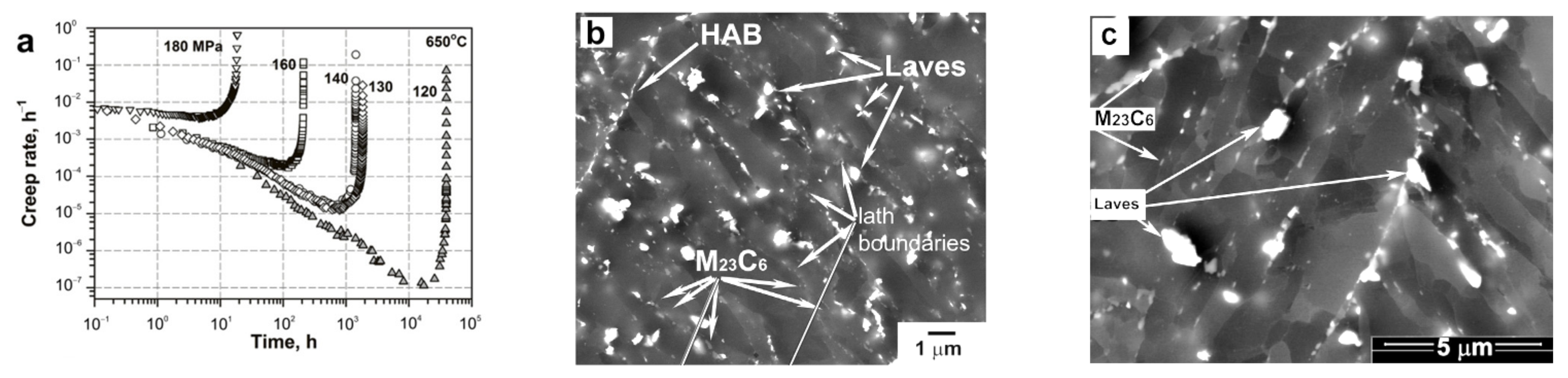
High creep resistance of the experimental 10Cr steel with 10Cr-3Co-2W-0.7Mo and 80 ppm B/30 ppm N in the long-term region at 120 MPa is provided by several factors, as suggested by Dudova et al. [8] and Mishnev et al. [15]:
- -
- The tempered martensite lath structure of the 10Cr steel (Figure 1) remains stable during the long-term creep testing for ~40,000 h at 650 °C, 120 MPa until rupture. Pronounced strain-induced lath coarsening appears during tertiary creep only;
- -
- M23C6 carbides demonstrate high coarsening resistance; their mean size increased from 70 to 120 nm during creep for ~40,000 h at 650 °C, wherein a significant part of carbide coarsening occurred during the secondary part of tertiary creep stage;
- -
- Although the N content is low (80 ppm) and, hence, V- and N-rich MX particles are not observed in the as-tempered steel, this V-rich MX phase precipitates during transient creep stage between 1000 and 10,000 h at 120 MPa. This provides additional precipitation strengthening and significant drop in the minimum creep rate by two orders of magnitude to 1.15 × 10⁻⁷ h−1 (or 3 × 10⁻¹¹ s−1) as compared with that at 130 and 140 MPa (Figure 16);
- -
- Low N content prevents the Z-phase formation. Small Z-phase particles were found to form between 30,000 and 40,000 of creep at 650 °C (not aging); however, their small size similar to M23C6 carbides did not affect negatively the creep resistance;
- -
- Therefore, nanoscale M23C6 carbides and MX carbonitrides can compensate for the negative effects of W depletion from the solid solution and extensive coarsening of the Laves phase particles.
4.3.2. Experimental 10Cr-0.2Re Steel
Rhenium is known as an effective strengthening element. Thus, alloying by 0.2%wt. Re in the 10.5Cr-2.5W-1Co-0.2Re-VMoNbNB steel (TOS 203 steel designed by Toshiba) resulted in a higher creep resistance as compared to the Re-free TOS 202 steel [46]. It was reported that rhenium contributes to the solid solution strengthening through it suppressing the W diffusion [46,70,72]. Since the B and N contents are similar in the 10Cr and 10Cr-0.2Re steels, the difference in their properties is mainly caused by the Re addition, as well as an increase in W by almost 1 %. The creep resistance of the 10Cr-0.2Re steel was studied by Fedoseeva et al. [39,40,41,71,74,75]:
- -
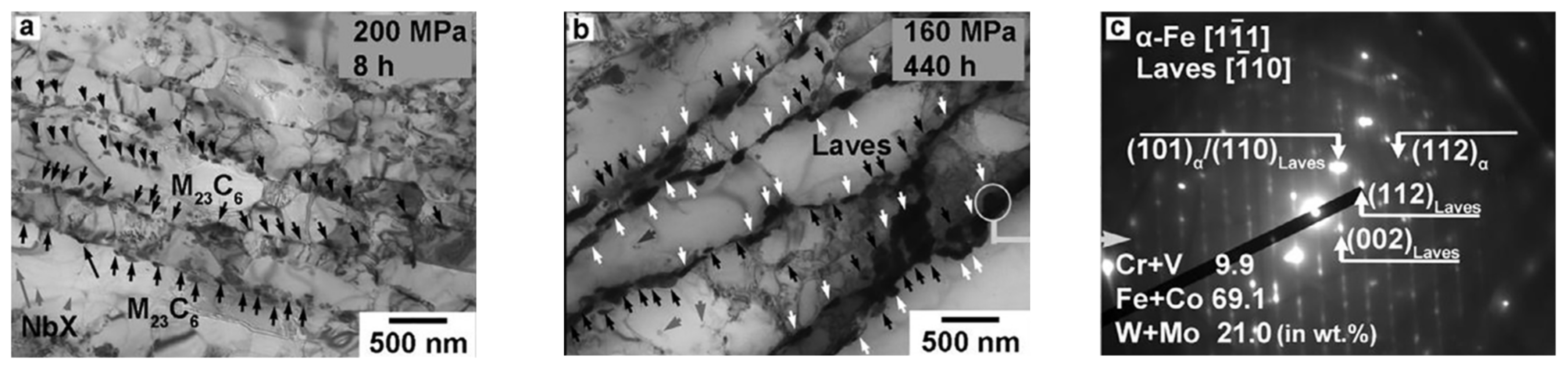
- In the short-term creep region, the M23C6 and Laves phase particles are more stable than in the 10Cr steel. Dense chains of M23C6 and Laves phase particles form on the lath boundaries during transient creep stage (Figure 17), which decreases the creep rate to 10−10 s−1 at 130 and 140 MPa. The coarsening rate constant for the M23C6 phase and Laves phase is about 3 and 1.4 times, respectively, lower than in the 10Cr steel. Moreover, a larger number density of carbides along the high-angle boundaries was revealed. Therefore, the more stable lath structure provides the higher creep strength in the high-stress region;
- -
- In contrast, at low stresses, the 10Cr-0.2Re steel has lower creep strength due to the creep strength breakdown appearance. It was found that M23C6 carbides and MX carbonitrides remained stable in size; however, the rapid coarsening of Laves phase particles occurred during creep. Although the mean size of Laves phase particles was 250 nm after creep rupture at 120 MPa for 13,495 h, the very large particles with size above 2 μm were observed, which could serve as nucleation sites for cracks. The coarsening of Laves phase particles facilitated the widening of martensitic lath and transformation of lath structure into the subgrain structure.
4.3.3. SuperVM12 Steel
Subanović et al. [54] showed that the SuperVM12 steel (11Cr-2W-1.8Co-140 ppm B-110 ppm N) is more creep-resistant than previous VM12-SHC steel (11Cr-1.5W-1.6Co-50 ppm B/600 ppm N) (Figure 13c) due to:
- -
- Dense and fine distribution of M23C6 carbides: their number density and coarsening rate are about 4 times higher and 3 times lower, respectively, than in the VM12-SHC steel (Table 4);
- -
- Beneficial effect of small B addition on the coarsening resistance of M23C6 carbides corresponds to observation of B in these particles. Incorporation of boron into the M23C6 was revealed to be approximately 2 at.% by atom probe tomography technique. Two different types of B distribution in M23C6 carbides were distinguished: in type I precipitates, a gradual decrease in boron content from the interface towards the center of the precipitate was observed (Figure 18a), whereas, in type II carbides, the B concentration was constant or slightly increasing (Figure 18b);
- -
- Larger number density and smaller size of MX precipitates than in the VM12-SHC steel. Boron was found in MX particles in the range of 0.3 at.% (Figure 15c);
- -
- Z-phase was not revealed after long-term creep during 23,844 h at 650 °C. The high creep resistance of the SuperVM12 steel at low stresses can be attributed to absence of Z-phase formation during long-term creep.
4.3.4. TAF650 Steel
In the TAF650 steel (11Cr-3W-3Co with 170–190 ppm B and 160–200 ppm N), as-tempered state, the highly inhomogeneous structure consisting of martensitic laths and subgrains was observed by Sawada et al. [49], Svoboda et al. [51,52], and Sklenicka et al. [50]. The dislocation density in the laths interiors varied from 7.7 × 10¹⁴ m−2 [49] to 2.58 × 10¹⁴ m−2 [51] depending on the tempering temperature (680 °C and 750 °C, respectively). Precipitates of M23C6 and Laves phase (Fe2W) were located along boundaries.
Andrén et al. studied the nature of high creep resistance of the previous TAF steel alloyed with high C (0.21%) and B (0.03%) contents, which exhibits the linear creep strength curve, not the sigmoidal curve, in contrast to the TAF650 steel (Figure 13d) [76]. Unusually high density of disk-like small MX precipitates (~10 nm) was observed. It was unexpected that boron was incorporated not only in M23C6 carbides but also in MX precipitates. The concentration of boron in M23C6 and MX reached 2 at% and 0.2 at%, respectively [76]. Therefore, in the TAF650 steel, strengthening by MX precipitates can also significantly affect the creep resistance. Thus, the fine VC and Nb(C,N,B) particles were observed in the TAF650 steel by Sklenicka et al. [50]. These precipitates were found to be replaced by Cr-, Nb-, V-rich Z-phase particles during long-term creep at 650 °C (18,870 h). Thermo-Calc calculation showed that 0.21% of the MX phase reduced to 0.05% at 650 °C due to the appearance of 0.18% Z-phase [50].
Therefore, it was supposed that the sigmoidal shape of the creep strength curve of the TAF650 steel was caused by the following reasons:
4.3.5. Experimental 12% Cr and 12% Cr-Ta Steels
Fedoseeva et al. studied the microstructure of the experimental 12% Cr (11.3Cr-3.9Co-2.4W-0.6Mo-90 ppm B/30 ppm N) and 12% Cr–Ta (11.4Cr-3.0Co-2.5W-0.6Mo-100 ppm B/30 ppm N-0.07Ta) steels with addition of Cu (0.76%) after creep at 120 MPa, 650 °C [17]. They showed that these 12% Cr steels do not exhibit the creep strength breakdown in this creep region in contrast to 9% Cr steel with conventional B and N content [17,20,21]. This was attributed to the remaining partial lath structure under the creep condition. The fine and stable particles of the M23C6 phase (with size about 100 nm) at the absence of Z-phase up to rupture (for ~3000 and ~8000 h, respectively, for the 12% Cr and 12% Cr –Ta steels) provided the small subgrain size of about 0.7 μm. The Ta addition resulted in the smaller size and higher volume fraction of M23C6 carbides and MX carbonitrides. It is interesting to note that, despite the low fraction of MX phase due to very low N content, these steels show high creep strength in the short-term region.
5. Strengthening Factors in the 9–12% Cr Steels
Let us consider the role of different mechanisms in the creep strength of high-chromium steels with increased B and decreased N contents. As it is known, the following factors affect the strength of material: solid solution, grain and subgrain boundaries, dislocations, and dispersed particles.
5.1. Solid Solution Strengthening
The solid solution strengthening of considered steels is mainly caused by chromium, tungsten, molybdenum, and cobalt. A small amount of rhenium is also used as a solid solution strengthening element in the 10Cr-0.2Re and TOS 203 steels.
Cr is the most strengthening element in the high-chromium steels. An increase in the Cr content from 9 to 12% can markedly increase the creep strength in the short-term creep region, for example, for the 11–12% Cr TAF650, 12Cr, and 12Cr-Ta steels, but not for the SuperVM12 steel (Figure 15). The W content varies from 1.5 to 3% in the steels, the Mo content varies from 0 to 0.7%, and Co content varies from 2 to 3%. Most of the 9% Cr advanced steels contain 3%W-0%Mo. On the other hand, the 9Cr-1.5W-0.6Mo steel shows the same creep strength in the short-term region (Figure 7 and Figure 8). The 10Cr-0.2Re steel shows higher creep strength up to the appearance of the creep strength breakdown in comparison with the 10Cr steel, probably due to the higher W content (3% instead of 2%), although the Mo equivalent (Mo + 1/2 W) is the same in these steels (1.7%), as well as due to the presence of Re. In the 11–12% Cr steels, there is also no distinct correlation between the content of W, Mo, and Co and the creep strength.
These solid-solution elements have more effect on the precipitation strengthening and boundary strengthening. Thus, the addition of 3% W is more effective to stabilize fine distribution of M23C6 carbides along the PAG and packet and lath boundaries than Mo [24]. Sawada et al., showed, on the TAF650 steel, that Fe2W Laves phase precipitates on the lath boundaries, in contrast to Fe2Mo Laves phase, which precipitates on the grain and packet boundaries in the modified 9Cr-1Mo steel [49]. Therefore, Fe2W Laves phase can retard the recovery of the lath structure. The addition of 3% Co provides an increase in the amount of MX carbonitrides and M23C6 carbides around PAG boundaries [19].
5.2. Boundary and Sub-Boundary Strengthening
The PAG size mainly depends on the heating temperature during normalization. As is shown in Table 1, the PAG size of considered steels significantly varies from 20 to 200 μm. However, a comparison of the time to rupture versus stress curves (Figure 7, Figure 8 and Figure 15) shows that the PAG size does not affect distinctly the creep strength. For example, the G115 steel with the PAG size of 100 μm and the SAVE12AD steel with 200 μm grain size show the same creep strength (Figure 8a). Moreover, the creep strength of the SuperVM12 steel (200 μm) is even lower than the creep strength of the TAF650 steel (33 μm) and 12% Cr and 12% Cr-Ta steels (50 μm) in the short-term creep region (Figure 15a).
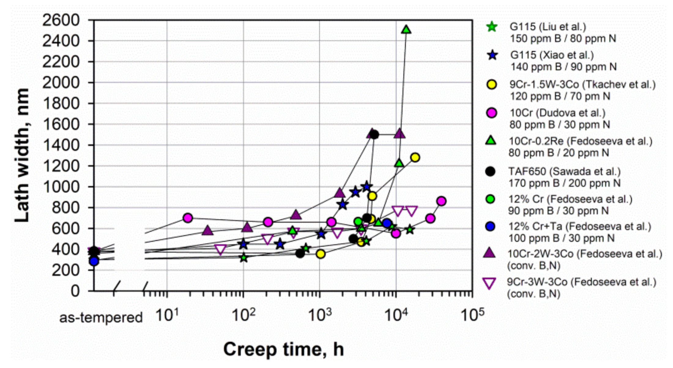
In the 9–12% Cr steels with tempered martensite lath structure, the sub-boundary hardening enhanced by fine distributions of precipitates along boundaries gives the most important strengthening mechanism for creep compared to the PAG boundaries [7]. The sub-boundary strengthening is inversely proportional to the width of lath or subgrains. The width of lath is nearly the same in most of the steels in the as-tempered state and comprises 300–400 nm (Figure 19). Evolution of lath width during creep depends on the stability of precipitates located on the lath boundaries, not only the M23C6 carbides but also the Laves phase. Figure 19 shows that the lath width slightly increases during creep. A sharp increase in the lath width or subgrain size above 1 μm usually corresponds to the transformation of the lath structure into the subgrain structure and the creep strength breakdown appearance as for the 9Cr-1.5W-3Co, 10Cr-0.2Re, and TAF650 steels.
5.3. Dislocation Strengthening
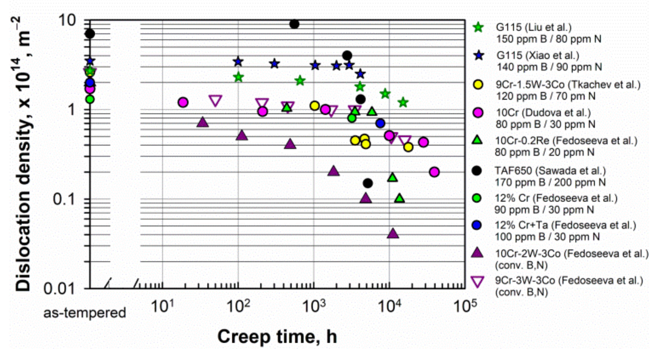
The dislocation density in the steels before creep depends on the tempering temperature. Figure 20 shows that the dislocation density comprised about 1–3 × 10¹⁴ m−2 in the as-tempered steels at 750–780 °C. Lower tempering temperatures increased the dislocation density, for example, up to 7.7 × 10¹⁴ m−2 in the TAF650 steel tempered at 680 °C [49].
For the long-term creep at elevated temperature, dislocation strengthening is not beneficial [7]. This is associated with the occurrence of recovery during creep. The excess dislocations can provoke rapid recovery, which leads to a decrease in the dislocation density and the transformation of the lath structure into the subgrain structure. Iseda et al. showed, on the 12% Cr steel [77], that tempering at 800 °C results in a longer creep rupture time at <70 MPa than tempering at 750 °C. In contrast to typical tempering at 750 °C, after tempering at 800 °C, the lower dislocation density provides less driving force for recovery and recrystallization during creep [7]. Probably, the high creep resistance of the SuperVM12 steel at low stresses can be partially attributed to the high tempering temperature of 780 °C, which provides a lower dislocation density.
A high dislocation density is retained in most steels during short-term and long-term creep (Figure 20). A noticeable decrease in the dislocation density usually corresponds to the appearance of the creep strength breakdown, as in the 9Cr-1.5W-3Co and 10Cr-0.2Re steels. In the TAF650 steel, the region of a pronounced decrease in the dislocation density corresponds to the sigmoidal shape of the creep strength curve (Figure 15). The high dislocation density in the G115 steel of 2–3 × 10¹⁴ m−2, which is stable up to approximately 4000 h of creep, is provided by fine Cu-rich particles precipitated during creep and then dissolving between 3000 and 4000 h of creep [33].
5.4. Precipitation Strengthening
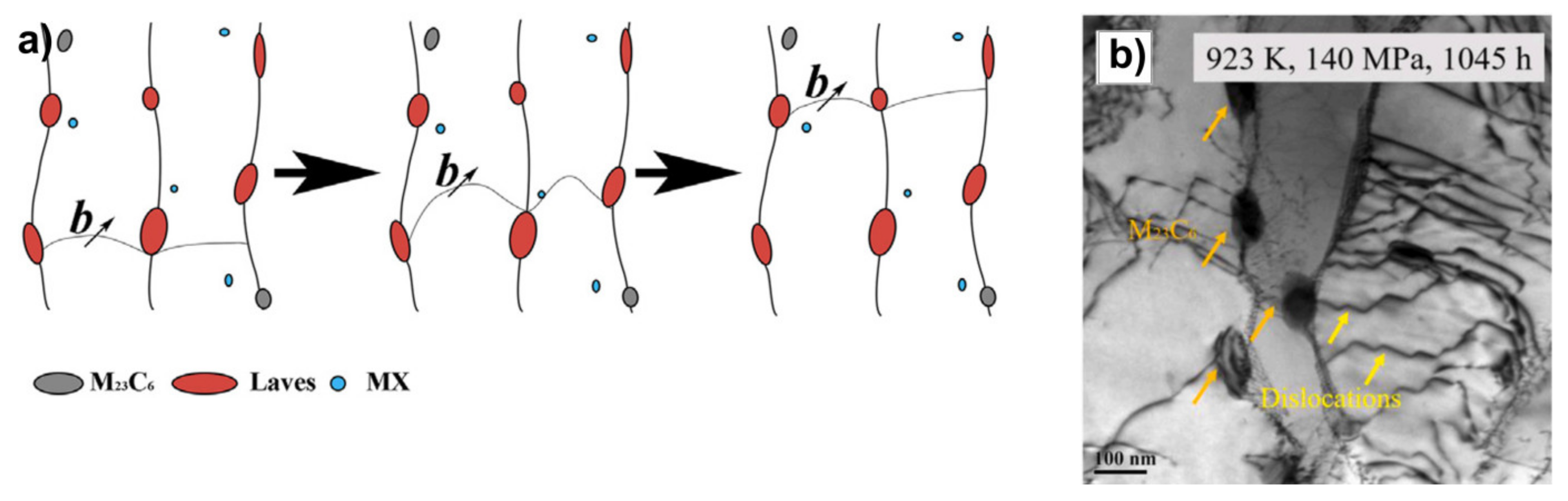
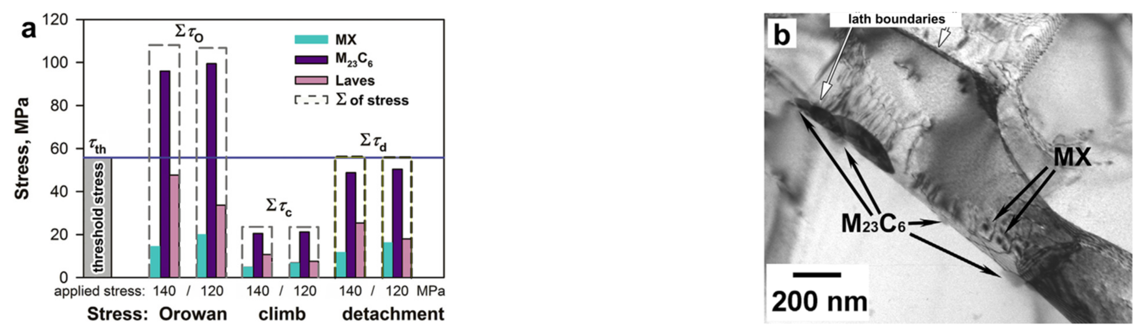
Threshold stress. The M23C6 carbides and Laves phase particles are the main phases precipitated on the boundaries of lath, blocks, packets and PAGs. Small carbides and Laves phase particles are the obstacles for dislocation glide along the laths, as can be seen in the scheme (Figure 21a) and the TEM micrograph (Figure 21b), showing the motion of dislocations in the presence of precipitates on the lath boundaries.
The stresses created by small precipitates cause the threshold stress for the onset of creep. Dudova et al. examined the creep behavior of the 10Cr steel in terms of threshold stress and found a high threshold stress of 111.5 MPa, which is about 30% larger than that in the P92-type steel [8]. The calculation of the stresses required for a dislocation to pass through particles at the minimum creep rate stage was carried out. The Orowan mechanism (to bow a dislocation between two particles), climb mechanism (to generate the additional length of dislocation to climb over an obstacle), and detachment mechanism (to detach the dislocation from an attractive particle after finishing the climb) were taken into account. It was revealed that the threshold stress is associated with the stress required for detachment of dislocations from M23C6 carbides, MX carbonitrides, and Laves phase particles after finishing the climb (Figure 22). Further, essentially stable M23C6 carbides exert the main part of threshold stress. The detachment stress can be calculated by equation [79]:
where G is the shear modulus, b is the Burgers vector, K—relaxation parameter, λ is the mean interparticle spacing, which is determined as [80]:
where d is the mean size of particles, Fv is the volume fraction of particles.
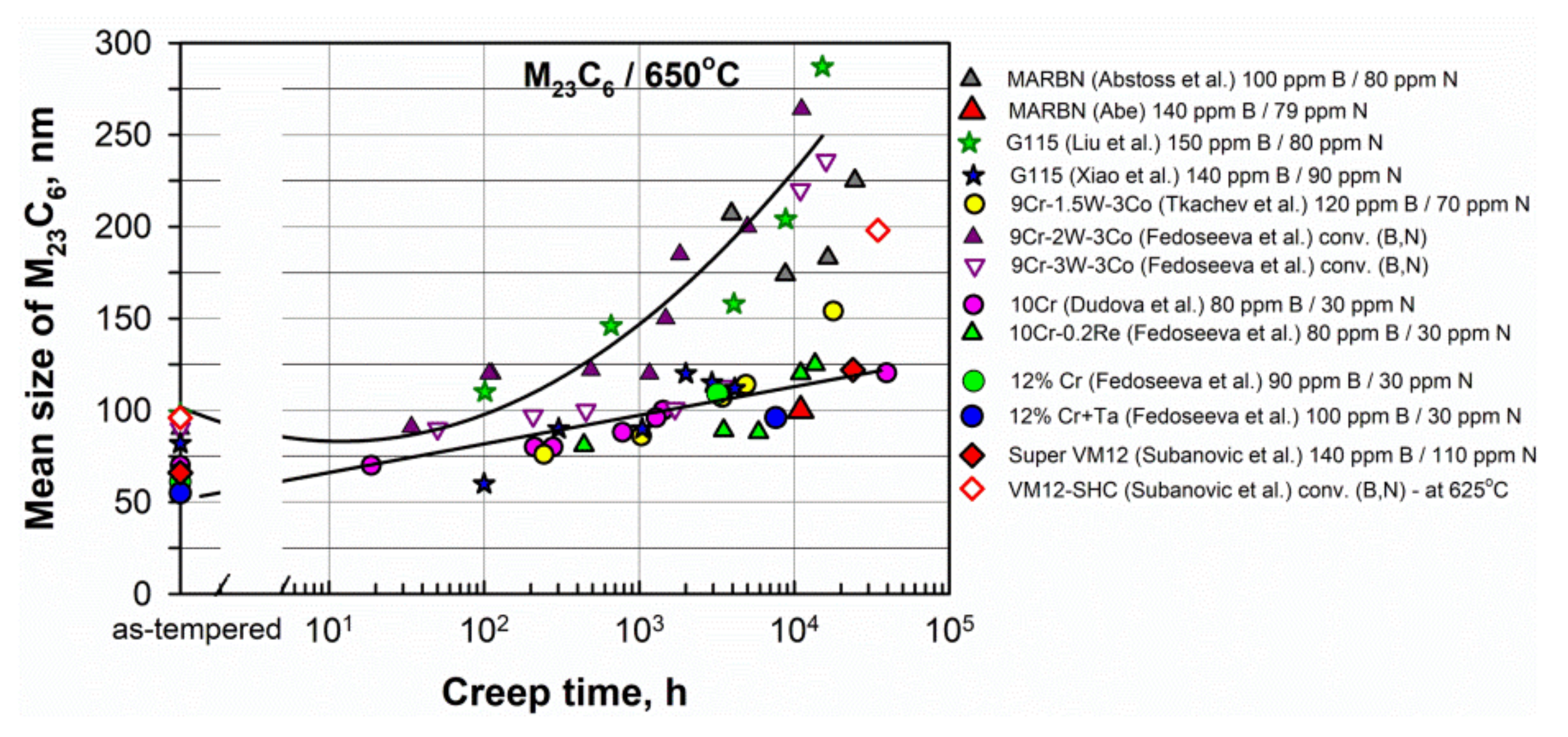
M23C6 carbides. Figure 23 shows that the mean sizes of M23C6 carbides in the as-tempered steels are in the range 50–100 nm. In most of the considered high B and low N steels, there is only a slight increase in the mean size at long-term creep over 10,000 h to about 120–150 nm, for example, in the MARBN, G115, 9Cr-1.5W-3Co, 10Cr, 10Cr-0.2Re, and SuperVM12 steels. Whereas, in the steels with conventional B content (the 9Cr-2W-3Co and 9Cr-3W-3Co steels), the pronounced coarsening of carbides to 200–300 nm occurs. Therefore, this confirms that the enrichment of steels by boron leads to a decrease in the size of carbides and an increase in their coarsening resistance under creep conditions.
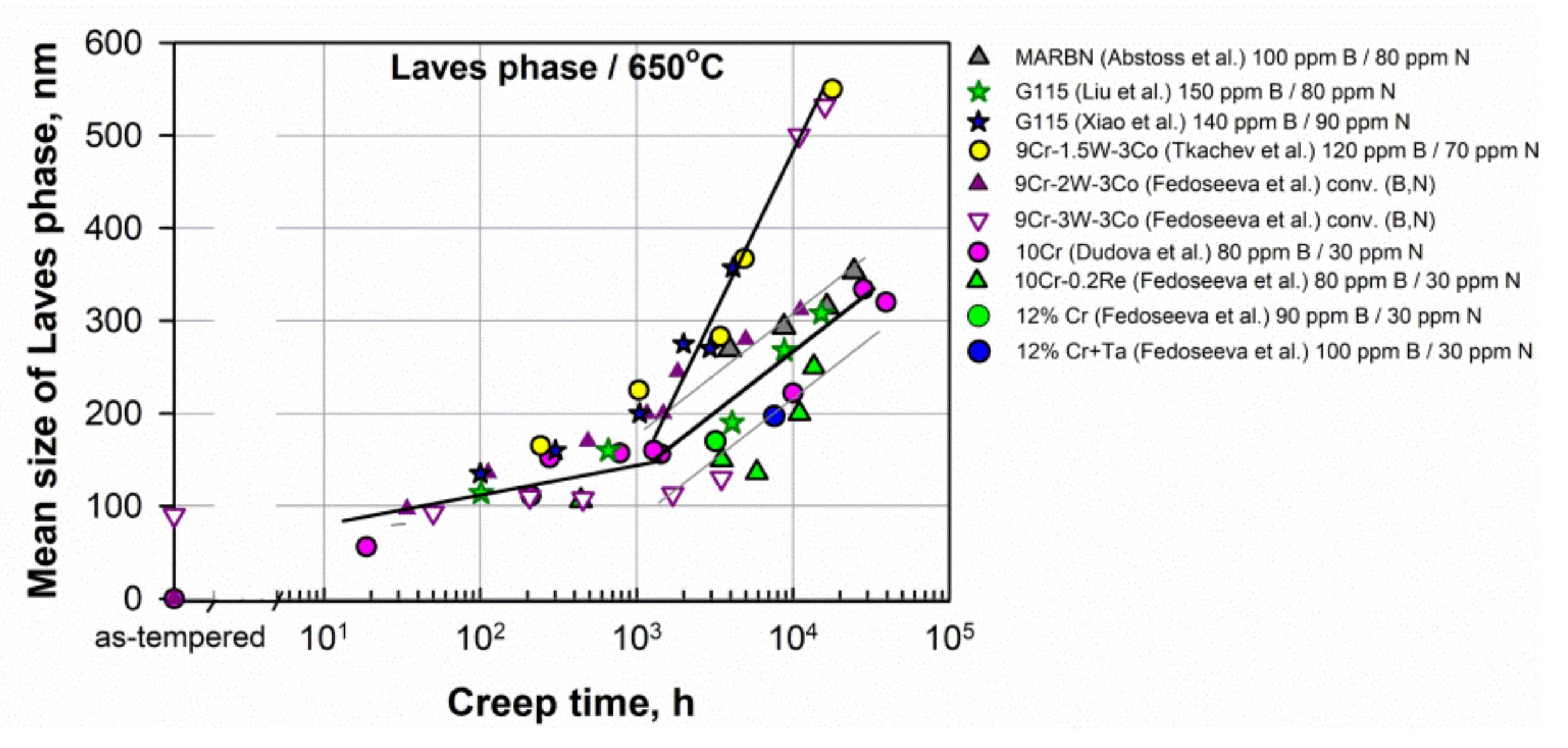
Laves phase. Laves phase particles grow during creep deformation, and their coarsening negatively affects the creep strength. Figure 24 presents the evolution of the mean size of Laves phase particles in some 9–12%Cr steels. Laves phase particles slightly grow up to approximately 1000 h of creep, and then the rapid coarsening occurs. Fedoseeva et al. showed that the first stage of Laves phase evolution is attributed to the formation of Laves phase nuclei along low-angle and high-angle boundaries [40]. At the second stage, the Ostwald ripening of Laves phase particles occurred. In the steels with a high B content and 2–3% W, a larger fraction of Laves phase nucleated at the lath boundaries than in the steels with conventional B content. These nuclei grew slowly due to fine M23C6 carbides that are densely distributed along the boundaries. Re also sufficiently decreased the coarsening of the Laves phase. In the 9Cr-1.5W-3Co steel, despite the high B content (120 ppm), the mean size of Laves phase particles increased rapidly to 500 nm and above during 10,000 h of creep, similar to the 9Cr-3W-3Co steel with a low B content (Figure 24). Due to low W content (1.5%), the coarse Laves phase particles precipitated on the high-angle boundaries during the first stage of evolution. This initiated the dissolution of fine particles on the low-angle boundaries and promoted fast coarsening of Laves phase particles [40].
MX phase. A decrease in the N content can lead to a decrease in the fraction of the MX phase in the steels with a high B and a low N content as compared to steels with conventional B and N contents. Consequently, the precipitation strengthening is reduced due to a small fraction of fine, homogeneously distributed in the lath interiors, MX particles. It can mainly concern the steels with a N content of lower than 70 ppm.
In order to provide sufficient strengthening from MX precipitates, the optimal content of 80–100 ppm N was suggested by Abe in the MARBN steel [7] and Rejeesh et al. in the P91 steel [66].
In the SuperVM12 steel, despite the N content having been reduced from 0.06 to 0.011% as compared to the previous VM12-SHC steel, a higher number density and a smaller size of MX particles were obtained [54]. It should be noted that boron was found in MX particles in the range of 0.3 at.%. Therefore, this MX phase is very stable, and the Z-phase was not revealed after long-term creep during 23,844 h at 650 °C.
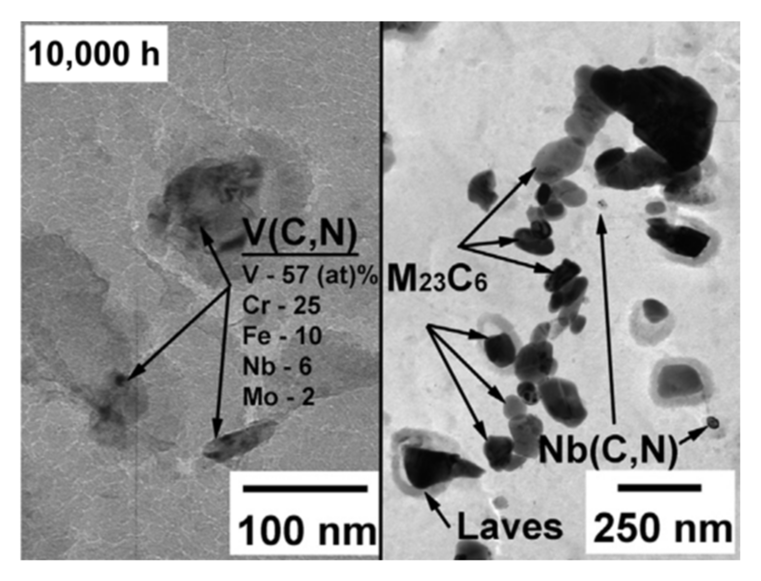
In some steels, such as the MARBN steel with 140 ppm B and 79 ppm N [11] and 10Cr steel with 80 ppm B and 30 ppm N [8,15], the precipitation of fine V-rich MX particles was revealed during the transient creep stage (Figure 25), which results in a pronounced decrease in the minimum creep rate and enhanced long-term creep resistance (Figure 12 and Figure 16).
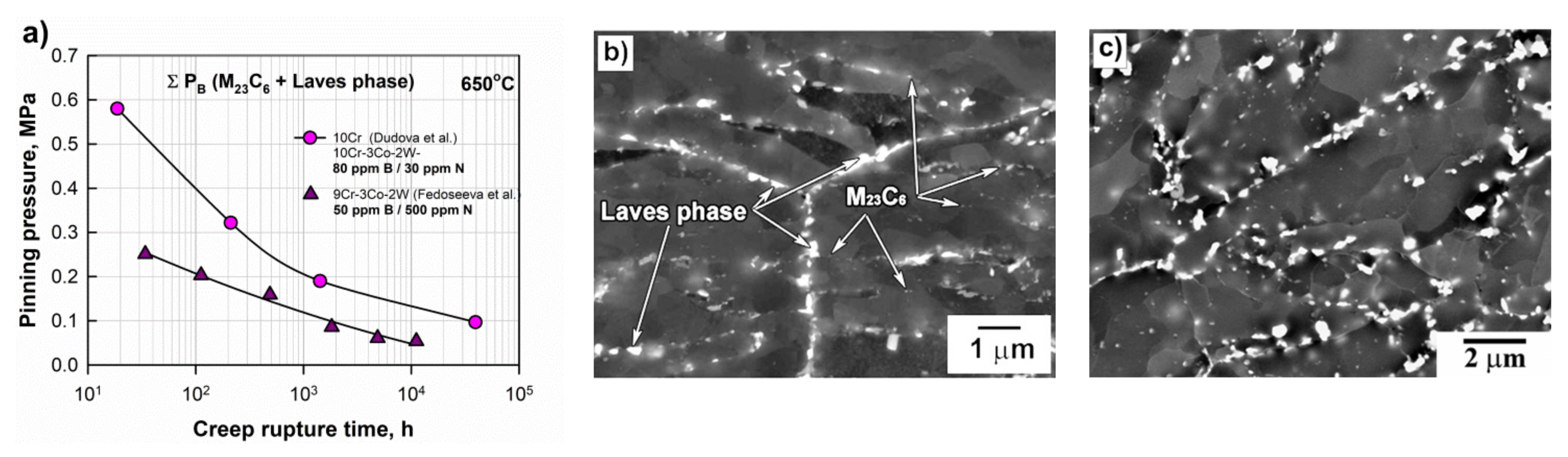
Pinning pressure. Fine and stable boundary precipitates effectively prevent the migration of lath boundaries due to high pinning pressure [8,16,18]. Figure 26 presents the comparison of the pinning pressure from the boundary M23C6 carbides and Laves phase particles in the 9Cr-2W-3Co steel with conventional B and N contents and the 10Cr steel with a high B and a low N content [8,21]. The pinning pressure was estimated as follows [8,21,81]:
where γ is the boundary surface energy per unit area, and Fv and d are the volume fraction and size of dispersed particles, respectively. D is the size of structural elements, i.e., the subgrain size or lath thickness.
The smaller size of M23C6 carbides in the 10Cr steel (70 nm) than in the 9Cr-2W-3Co steel (90 nm) in the as-tempered condition and higher coarsening resistance (120 nm after 39,437 h instead of 264 nm after 11,151 h) result in pinning pressures that are approximately two times higher in both the short-term and long-term creep regions (Figure 26a). The higher pinning pressure was attained in the 10Cr steel despite the fact that the volume fraction of M23C6 carbides is slightly higher in the 9Cr-2W-3Co steel (2.27%) than in the 10Cr steel (2.05%). It should be noted that the coarsening rate of the Laves phase was nearly the same in these steels, which was shown by Fedoseeva et al. [40]. Higher pinning pressures provide the stable lath structure in the 10Cr steel up to long-term creep (Figure 26b), whereas the well-defined subgrain structure was formed in the 9Cr-2W-3Co steel during short-term creep (Figure 26c).
Therefore, an increase in the B content and a decrease in the N content is one of many factors affecting the creep strength of 9–12% Cr martensitic steels. The greatest effect is associated with enrichment of M23C6 carbides by boron, which enhances the coarsening resistance of carbides. In turn, fine dispersion of M23C6 carbides on the PAG boundaries during creep can provide the slower coarsening of Laves phase particles. Moreover, the MX phase, despite the low N content, can enhance the creep strength in the long-term region. Firstly, it was reported that the MX phase contains boron (0.2–0.3 at.%) and demonstrates high stability and high coarsening resistance. Secondly, in many steels with 10–12% Cr, the Z-phase was not revealed after creep for rather long times. Therefore, the dispersion strengthening can be sufficiently increased by an increase in the B content and a decrease in the N content. This provides a stable lath structure over a long creep time and prevents the transformation of the lath structure into a subgrain structure.
6. Summary
The review of the 9–12% Cr heat-resistant martensitic steels with increased boron and decreased nitrogen contents in comparison with similar steels with conventional B/N contents shows the following:
- -
- The approach to alloying by the increased B (80–150 ppm) and decreased N (30–100 ppm) contents is successfully applied to advanced 9% Cr, as well as 10–12% Cr martensitic steels. The predicted long-term creep rupture strength at 650 °C for 100,000 h attained:
- ○
- 80–110 MPa for the 9% Cr steels, such as the MARBN (9Cr-3Co-3W-100–140 ppm B/30–80 ppm N), G115 (9Cr-3Co-3W-1Cu-150 ppm B/80 ppm N), and SAVE12AD (9Cr-3Co-3W-0.04Nd-100 ppm B/100 ppm N) steels, which sufficiently exceeds the creep strength for the 9% Cr Co-free P92 steel (~60 MPa) and 3% Co-modified P92 steels (~65–70 MPa) with conventional B (~50 ppm) and N (~500 ppm) contents;
- ○
- 110 MPa for the 10% Cr experimental steel (10Cr-3Co-2W-0.7Mo-80 ppm B/30 ppm N), which sufficiently exceeds the creep strength for the 11%Cr Co-free P122 steel (~45 MPa), 10% Cr Co-containing NF12 steel (10Cr-2Co-2.5W-50 ppm B/200 ppm N) (40 MPa), and advanced 10Cr-3Co-1.8W-100 ppm B/200 ppm N (TOS 110) steel (80 MPa);
- ○
- Approximately 65 MPa for the 11–12% Cr steels, such as SuperVM12 steel (11Cr-1.8Co-2W-0.5Mo-140 ppm B/110 ppm N), which is sufficiently higher than that for the previous VM12-SHC steel (~50 MPa), 11%Cr Co-free P122 steel (~45 MPa), and slightly higher than that for 9% Cr P92 steel (~60 MPa) with conventional B (~50 ppm) and N (~500–600 ppm) contents;
- -
- An increase in the B content and a decrease in the N content enhance the creep resistance in the long-term region at a low stress, while the creep strength in the short-term region at the higher stresses corresponds to that for the steels with conventional B and N contents;
- -
- A high B content at a low N content effectively increases the coarsening resistance of M23C6 carbides during creep at 650 °C in all considered steels;
- -
- A positive effect of B on the creep strength is associated with enrichment of M23C6 carbides located near the PAG boundaries, which increases their coarsening resistance during creep. Stable M23C6 carbides are able to impede the recovery of the lath structure in the vicinity of PAG boundaries and, hence, retard the local deformation in the PAG boundary regions;
- -
- Even if the B content was already high in steel, then lowering the N content less than the solubility limit can increase the long-term creep rupture strength due to full utilization of soluble boron in the matrix and M23(B,C)6-type carbides;
- -
- Precipitation of small MX particles during the transient stage of long-term creep effectively reduces the creep rate and increases the time to rupture, as was shown in the MARBN steel with 140 ppm B and 79 ppm N and the 10Cr experimental steel with 80 ppm B and 30 ppm N;
- -
- An increase in the B content and a decrease in the N content is an effective way to enhance the dispersion strengthening by: fine and highly coarsening-resistant M23C6 carbides, which, in turn, can provide the slower coarsening of Laves phase particles; moreover, the MX phase, despite the low N content, can enhance the creep strength in the long-term region. This provides a stable tempered martensite lath structure over a long creep time and prevents the transformation of the lath structure into a subgrain structure.
Funding
This study was financially supported by the Russian Science Foundation No. 22–29-00145, https://rscf.ru/project/22–29-00145/ (accessed on 1 January 2022).
Institutional Review Board Statement
Not applicable.
Informed Consent Statement
Not applicable.
Data Availability Statement
The data presented in this study are available on request from the corresponding authors of the articles from the reference list.
Conflicts of Interest
The author declares no conflict of interest.
References
- Abe, F. Research and development of heat-resistant materials for advanced USC power plants with steam temperatures of 700 °C and above. Engineering 2015, 1, 211–224. [Google Scholar] [CrossRef] [Green Version]
- Abe, F.; Kern, T.-U.; Viswanathan, R. Creep-Resistant Steels; Woodhead Publishing: Cambridge, UK, 2008. [Google Scholar]
- Xie, X.; Wu, Y.; Chi, C.; Zhang, M. Superalloys for Advanced Ultra-Super-Critical Fossil Power Plant Application. In Superalloys; Aliofkhazraei, M., Ed.; IntechOpen: London, UK, 2015; pp. 51–76. [Google Scholar] [CrossRef] [Green Version]
- Maruyama, K.; Sawada, K.; Koike, J. Strengthening mechanisms of creep resistant tempered martensitic steel. ISIJ Int. 2001, 41, 641–653. [Google Scholar] [CrossRef]
- Masuyama, F.; Yamaguchi, T. New ferritic steel beyond Grade 92 and its creep degradation assessment by hardness method for Grade 91. In Proceedings of the ASME 2014 Symposium on Elevated Temperature Application of Materials for Fossil, Nuclear, and Petrochemical Industries, Seattle, WA, USA, 25–27 March 2014; No. ETAM2014-1007. pp. 54–61. [Google Scholar] [CrossRef] [Green Version]
- Yoshizawa, M.; Igarashi, M.; Moriguchi, K.; Iseda, A.; Armaki, H.G.; Maruyama, K. Effect of precipitates on long-term creep deformation properties of P92 and P122 type advanced ferritic steels for USC power plants. Mater. Sci. Eng. A 2009, 510–511, 162–168. [Google Scholar] [CrossRef]
- Abe, F. New martensitic steels. In Materials for Ultra-Supercritical and Advanced Ultra-Supercritical Power Plants; Di Gianfrancesco, A., Ed.; Woodhead Publishing: Cambridge, UK, 2017; pp. 323–374. [Google Scholar] [CrossRef]
- Dudova, N.; Mishnev, R.; Kaibyshev, R. Creep behavior of a 10%Cr heat-resistant martensitic steel with low nitrogen and high boron contents at 650 °C. Mater. Sci. Eng. A 2019, 766, 138353. [Google Scholar] [CrossRef]
- Mitsuhara, M.; Yamasaki, S.; Miake, M.; Nakashima, H.; Nishida, M.; Kusumoto, J.; Kanaya, A. Creep strengthening by lath boundaries in 9Cr ferritic heat resistant steel. Philos. Mag. Lett. 2016, 96, 76–83. [Google Scholar] [CrossRef]
- Dudko, V.; Belykov, A.; Kaibyshev, R. Evolution of lath substructure and internal stresses in a 9% Cr steel during creep. ISIJ Int. 2017, 57, 540–549. [Google Scholar] [CrossRef] [Green Version]
- Semba, H.; Abe, F. Alloy design and creep strength of advanced 9%Cr USC boiler steels containing high concentration of boron. Energy Mater. 2007, 1, 238–244. [Google Scholar] [CrossRef]
- Hald, J. Microstructure and long-term creep properties of 9–12% Cr steels. Int. J. Press. Vessels Pip. 2008, 85, 30–37. [Google Scholar] [CrossRef]
- Abe, F. Effect of boron on microstructure and creep strength of advanced ferritic power plant steels. Procedia Eng. 2011, 10, 94–99. [Google Scholar] [CrossRef] [Green Version]
- Horiuchi, T.; Igarashi, M.; Abe, F. Improved utilization of added B in 9Cr heat-resistant steels containing W. ISIJ Int. 2002, 42, S67–S71. [Google Scholar] [CrossRef] [Green Version]
- Mishnev, R.; Dudova, N.; Kaibyshev, R. On the origin of the superior long-term creep resistance of a 10% Cr steel. Mater. Sci. Eng. A 2018, 713, 161–173. [Google Scholar] [CrossRef]
- Liu, Z.; Liu, Z.; Chen, Z.; Wang, X.; Bao, H.; Dong, C. Microstructure and creep strength evolution in G115 steel during creep at 650 °C. Mater. Res. Express 2020, 7, 016528. [Google Scholar] [CrossRef]
- Fedoseeva, A.; Nikitin, I.; Fedoseev, A.; Kaibyshev, R. Evolution of the tempered lath structure of the 12%Cr steels with low N and high B contents during creep. IOP Conf. Ser. Mater. Sci. Eng. 2021, 1014, 012011. [Google Scholar] [CrossRef]
- Tkachev, E.; Belyakov, A.; Kaibyshev, R. Creep behavior and microstructural evolution of a 9%Cr steel with high B and low N contents. Mater. Sci. Eng. A 2018, 725, 228–241. [Google Scholar] [CrossRef] [Green Version]
- Helis, L.; Toda, Y.; Hara, T. Effect of cobalt on the microstructure of tempered martensitic 9Cr steel for ultra-supercritical power plants. Mater. Sci. Eng. A 2009, 510, 88–94. [Google Scholar] [CrossRef]
- Dudova, N.; Plotnikova, A.; Molodov, D.; Belyakov, A.; Kaibyshev, R. Structural changes of tempered martensitic 9%Cr–2%W–3%Co steel during creep at 650 °C. Mater. Sci. Eng. A 2012, 534, 632–639. [Google Scholar] [CrossRef]
- Fedoseeva, A.; Dudova, N.; Kaibyshev, R. Creep strength breakdown and microstructure evolution in a 3%Co modified P92 steel. Mater. Sci. Eng. A 2016, 654, 1–12. [Google Scholar] [CrossRef]
- Fedoseeva, A.; Dudova, N.; Kaibyshev, R. Creep behavior and microstructure of a 9Cr–3Co–3W martensitic steel. J. Mater. Sci. 2016, 52, 2974–2988. [Google Scholar] [CrossRef]
- Kipelova, A.; Odnobokova, M.; Belyakov, A.; Kaibyshev, R. Effect of Co on creep behavior of a P911 steel. Metall. Mater. Trans. A 2012, 44, 577–583. [Google Scholar] [CrossRef]
- Abe, F. Progress in Creep-Resistant Steels for High Efficiency Coal-Fired Power Plants. J. Press. Vessel Technol. 2016, 138, 040804. [Google Scholar] [CrossRef]
- Abe, F.; Tabuchi, M.; Tsukamoto, S. Mechanisms for boron effect on microstructure and creep strength of ferritic power plant steels. Energy Mater. 2012, 4, 166–174. [Google Scholar] [CrossRef]
- Abe, F.; Tabuchi, M.; Semba, H.; Igarashi, M.; Yoshizawa, M.; Komai, N.; Fujita, A. Feasibility of MARBN steel for application to thick section boiler components in USC power plant at 650 °C. In Proceedings of the 5th EPRI International Conference, Marco Island, FL, USA, 3–5 October 2007; pp. 92–106. [Google Scholar] [CrossRef]
- Abstoss, K.G.; Schmigalla, S.; Schultze, S.; Mayr, P. Microstructural changes during creep and aging of a heat resistant MARBN steel and their effect on the electrochemical behaviour. Mater. Sci. Eng. A 2019, 743, 233–242. [Google Scholar] [CrossRef]
- Yan, P.; Liu, Z.-D.; Liu, W.; Bao, H.-S.; Weng, Y.-Q.J. Hot Deformation Behavior of a New 9% Cr Heat Resistant Steel G115. J. Iron Steel Res. Int. 2013, 20, 73–79. [Google Scholar] [CrossRef]
- Yan, P.; Liu, Z.; Bao, H.; Weng, Y.; Liu, W. Effect of normalizing temperature on the strength of 9Cr–3W–3Co martensitic heat resistant steel. Mater. Sci. Eng. A 2014, 597, 148–156. [Google Scholar] [CrossRef]
- Liu, Z.; Bao, H.; Chen, Z.; Xu, S.; Zhao, H.; Wang, Q. Creep Strength and Oxidation Resistance of Industrially Made G115 Steel Pipe. In Energy Materials 2017; Liu, X., Liu, Z., Brinkman, K., Das, S., Dryepondt, S., Fergus, J.W., Guo, Z., Han, M., Hawk, J.A., Horita, T., et al., Eds.; The Minerals, Metals & Materials Series; Springer: Cham, Switzerland, 2017; pp. 153–159. [Google Scholar] [CrossRef]
- Igarashi, M. Alloy design philosophy of creep-resistant steels. In Creep-Resistant Steels; Woodhead Publishing Series in Metals and Surface Engineering; Woodhead Publishing: Cambridge, UK, 2008; pp. 539–572. [Google Scholar] [CrossRef]
- Xiao, B.; Xu, L.; Zhao, L.; Jing, H.; Han, Y. Deformation-mechanism-based creep model and damage mechanism of G115 steel over a wide stress range. Mater. Sci. Eng. A 2019, 743, 280–293. [Google Scholar] [CrossRef]
- Xiao, B.; Xu, L.; Tang, Z.; Zhao, L.; Jing, H.; Han, Y.; Li, H. A physical-based yield strength model for the microstructural degradation of G115 steel during long-term creep. Mater. Sci. Eng. A 2019, 747, 161–176. [Google Scholar] [CrossRef]
- Hamaguchi, T.; Okada, H.; Kurihara, S.; Hirata, H.; Yoshizawa, M.; Iseda, A. Microstructural evaluation of 9Cr-3W-3Co-Nd-B heat-resistant steel (SAVE12AD) after long-term creep deformation. In Proceedings of the ASME 2017 Pressure Vessels and Piping Conference PVP2017, Waikoloa, HI, USA, 16–20 July 2017; American Society of Mechanical Engineers: New York, NY, USA, 2017; PVP2017-65241. [Google Scholar] [CrossRef]
- Hamaguchi, T.; Kurihara, S.; Hirata, H.; Okada, H. Creep rupture properties and microstructures of 9Cr–3Co–3W-Nd-B steel welded joints. Mater. Sci. Eng. A 2022, 831, 142231. [Google Scholar] [CrossRef]
- Hamaguchi, T.; Okada, H.; Hirata, H.; Kurihara, S.; Semba, H.; Yoshizawa, M. Creep Rupture Strength and Microstructures of SAVE12AD Welded Joints; Technical Report No. 119; Nippon Steel & Sumitomo Metal: Tokyo, Japan, 2018; pp. 32–38. [Google Scholar]
- Masuyama, F. New developments in steels for power station boilers. In Advanced Heat Resistant Steels for Power Generation; Viswanathan, R., Nutting, J.W., Eds.; IOM Communication Limited: London, UK, 1999; pp. 3–48. [Google Scholar]
- Tkachev, E.; Belyakov, A.; Kaibyshev, R. Creep strength breakdown and microstructure in a 9%Cr steel with high B and low N contents. Mater. Sci. Eng. A 2020, 772, 138821. [Google Scholar] [CrossRef]
- Fedoseeva, A.; Nikitin, I.; Dudova, N.; Kaibyshev, R. Coarsening of Laves phase and creep behaviour of a Re-containing 10% Cr-3% Co-3% W steel. Mater. Sci. Eng. A 2021, 812, 141137. [Google Scholar] [CrossRef]
- Fedoseeva, A.; Nikitin, I.; Tkachev, E.; Mishnev, R.; Dudova, N.; Kaibyshev, R. Effect of alloying on the nucleation and growth of Laves phase in the 9–10%Cr-3%Co martensitic steels during creep. Metals 2021, 11, 60. [Google Scholar] [CrossRef]
- Fedoseeva, A.; Nikitin, I.; Dudova, N.; Kaibyshev, R. Strain and temperature contributions to structural evolution in a Re-containing 10% Cr-3% Co-3% W steel during creep. Mater. High Temp. 2021, 38, 237–246. [Google Scholar] [CrossRef]
- Tsuda, T.; Yamada, M.; Ishii, R.; Watanabe, O. Advances in Turbine Materials, Design and Manufacturing. In Proceedings of the Fourth International Charles Parsons Turbine Conference, Newcastle upon Tyne, UK, 4–6 November 1997; Strang, A., Ed.; CRC Press: Boca Raton, FL, USA, 1997; Volume 689. [Google Scholar]
- Viswanathan, R.; Bakker, W. Materials for Ultrasupercritical Coal Power Plants—Turbine Materials: Part II. J. Mater. Eng. Perform. 2001, 10, 96–101. [Google Scholar] [CrossRef]
- Takasawa, K.; Miki, K. Development of high-and intermediate-pressure steam turbine rotors for efficient fossil power generation technology. JSW Tech. Rev. 2018, 20, 15–22. Available online: https://www.jsw.co.jp/en/product/technology/technical_review/technical_review1542456266489048621/main/0/link/File024476424.pdf (accessed on 1 January 2020).
- Hidaka, K.; Fukui, Y.; Nakamura, S.; Kaneko, R.; Tanaka, Y.; Fujita, T. Development of Heat Resistant 12CrWCoB Steel Rotor for USC Power Plant. In Advanced Heat Resistant Steels for Power Generation; Viswanathan, R., Nutting, J., Eds.; The Institute of Materials: London, UK, 1999; pp. 482–493. [Google Scholar]
- Ishii, R.; Tsuda, Y.; Yamada, M. High strength 12% Cr heat resisting steel for high temperature steam turbine blade. In Steel Forgings, Second Volume; ASTM STP 1259; Nisbett, E.G., Melilli, A.S., Eds.; American Society for Testing and Materials: West Conshohocken, PA, USA, 1997; pp. 317–329. [Google Scholar]
- Fujita, T. Advances in 9–12%Cr heat resistant steels for power plant. In Proceedings of the 3rd Conference on Advances in Material Technology for Fossil Power Plants, London, UK, 5–6 April 2001; Viswanathan, R., Bakker, W.T., Parker, J.D., Eds.; ASM International: Materials Park, OH, USA; pp. 33–65.
- Fujita, T.; Takahashi, N. The Effects of V and Nb on the Long Period Creep Rupture Strength of 12 %Cr Heat-resisting Steel Containing Mo and B. Trans. Iron Steel Inst. Jpn. 1978, 18, 269–278. [Google Scholar] [CrossRef]
- Sawada, K.; Takeda, M.; Maruyama, K.; Ishii, R.; Yamada, M.; Nagae, Y.; Komine, R. Effect of W on recovery of lath structure during creep of high chromium martensitic steels. Mater. Sci. Eng. A 1999, 267, 19–25. [Google Scholar] [CrossRef]
- Sklenicka, V.; Kucharova, M.; Svoboda, M.; Kloc, L.; Bursık, J.; Kroupa, A. Long-term creep behavior of 9–12%Cr power plant steels. Mat. Char. 2003, 51, 35–48. [Google Scholar] [CrossRef]
- Svoboda, M.; Dlouhý, A.; Podstranská, I.; Sklenička, V.; Mayer, K.H. Microstructural changes in creep of TAF 650 steel at 650 °C. In Proceedings of the 9th International Metallurgical Conference METAL 2000, Ostrava, Czech Republic, 16–18 May 2000; pp. 1–8. [Google Scholar]
- Svoboda, M.; Bursik, J.; Podstranska, I.; Krouppa, A.; Sklenicka, V.; Mayer, K.H. High temperature creep behaviour and microstructural changes of TAF 650 steel. In Materials for Advanced Power Engineering; Lecomte-Beckers, J., Carton, M., Schubert, F., Ennis, P.J., Eds.; Forschungszentrum Jülich GmbH: Liege, Belgium, 2002; pp. 1521–1530. [Google Scholar]
- Subanović, M.; Pirón, J.; Zeller, F.; Jarrar, M.; Schneider, A. Development of a new high-performance martensitic heat-resistant steel for boiler applications. In Proceedings of the ASME 2018 Symposium on Elevated Temperature Application of Materials for Fossil, Nuclear, and Petrochemical Industries, Seattle, WA, USA, 3–5 April 2018; No. ETAM2018-6748, V001T01A008. pp. 1–5. [Google Scholar] [CrossRef] [Green Version]
- Subanović, M.; Abellán, J.P.; Gauss, A.; Jarrar, M.; Schneider, A. Super VM12—A new 12% Cr boiler steel. In Proceedings of the Joint EPRI–123HiMAT International Conference on Advances in High Temperature Materials, Nagasaki, Japan, 21–24 October 2019; Shingledecker, J., Takeyama, M., Eds.; ASM International: Materials Park, OH, USA, 2019; pp. 205–216. [Google Scholar]
- Schneider, A.; Subanović, M.; Abellan, J.P. Long-term evolution of microstructure in VM12-SHC. In Proceedings of the 7th International Conference on Advances in Materials Technology for Fossil Power Plants, Waikoloa, HI, USA, 22–25 October 2013; pp. 1093–1103. [Google Scholar]
- Nikitin, I.; Fedoseeva, A.; Kaibyshev, R. Strengthening mechanisms of creep-resistant 12%Cr–3%Co steel with low N and high B contents. J. Mater. Sci. 2020, 55, 7530–7545. [Google Scholar] [CrossRef]
- Yadav, S.D.; Kalácska, S.; Dománková, M.; Yubero, D.C.; Resel, R.; Groma, I.; Poletti, C. Evolution of the substructure of a novel 12% Cr steel under creep conditions. Mat. Char. 2016, 115, 23–31. [Google Scholar] [CrossRef]
- Yadav, S.D.; El-Tahawy, M.; Kalácska, S.; Dománková, M.; Yubero, D.C.; Poletti, C. Characterizing dislocation configurations and their evolution during creep of a new 12% Cr steel. Mat. Char. 2017, 134, 387–397. [Google Scholar] [CrossRef]
- Sieverts, A.; Zapf, G. Eisen und Stickstoff. Z. Phys. Chem. 1935, 172, 314–315. [Google Scholar] [CrossRef]
- Satir-Kolorz, A.H.; Feichtinger, H.K. On the solubility of nitrogen in liquid iron and steel alloys using elevated pressure/Über die löslichkeit von stickstoff in eisen-und stahllegierungen unter erhöhtem druck. Int. J. Mater. Res. 1991, 82, 689–697. [Google Scholar] [CrossRef]
- ASM Handbook Committee. Vacuum Induction Melting. In ASM Handbook, Volume 15: Casting; ASM International: Materials Park, OH, USA, 1988; pp. 1–8. [Google Scholar] [CrossRef]
- El-Kashif, E.; Asakura, K.; Shibata, K. Effects of Nitrogen in 9Cr–3W–3Co Ferritic Heat Resistant Steels Containing Boron. ISIJ Int. 2002, 42, 1468–1476. [Google Scholar] [CrossRef]
- Sakuraya, K.; Okada, H.; Abe, F. BN type inclusions formed in high Cr ferritic heat resistant steel. Energy Mater. 2006, 1, 158–166. [Google Scholar] [CrossRef]
- Abe, F.; Tabuchi, M.; Tsukamoto, S.; Liu, Y. Alloy design of tempered martensitic 9Cr-boron steel for A-USC boilers. In Proceedings of the 7th EPRI Conference on Advances in Materials Technology for Fossil Power Plants, Waikoloa, HI, USA, 22–25 October 2013; pp. 1127–1138. [Google Scholar]
- Abe, F.; Ohba, T.; Miyazaki, H.; Toda, Y.; Tabuchi, M. Effect of boron nitrides and aluminum nitrides on long-term creep life and rupture ductility of martensitic 9 to 12Cr steels. In Proceedings of the Joint EPRI–123HiMAT International Conference on Advances in High Temperature Materials, Nagasaki, Japan, 21–24 October 2019; Shingledecker, J., Takeyama, M., Eds.; ASM International: Materials Park, OH, USA, 2019; pp. 336–347. [Google Scholar]
- Rejeesh, R.; Bhattacharya, A.; Haldar, C.; Mitra, R.; Chakrabarti, D.; Das, C.R.; Albert, S.K.; Bhadur, A.K. Relative effect of B and N concentrations on the microstructural stability and mechanical properties of modified 9Cr-1Mo steel. J. Alloys Compd. 2021, 867, 158971. [Google Scholar] [CrossRef]
- Abe, F. Precipitate design for creep strengthening of 9% Cr tempered martensitic steel for ultra-supercritical power plants. Sci. Technol. Adv. Mater. 2008, 9, 013002. [Google Scholar] [CrossRef] [Green Version]
- Sekido, N.; Hatta, T.; Maruyama, K.; Yoshimi, K.; Yonemura, M. Microstructure evolution in a high-boron ferritic steel during creep at 650 °C. In Proceedings of the Joint EPRI–123HiMAT International Conference on Advances in High Temperature Materials, Nagasaki, Japan, 21–24 October 2019; Shingledecker, J., Takeyama, M., Eds.; ASM International: Materials Park, OH, USA, 2019; pp. 156–161. [Google Scholar]
- Lundin, L.; Fällman, S.; Andrén, H.O. Microstructure and mechanical properties of a 10% chromium steel with improved creep resistance at 600°C. Mater. Sci. Technol. 1997, 13, 233–242. [Google Scholar] [CrossRef]
- Fukuda, M.; Tsuda, Y.; Yamashita, K.; Shinozaki, Y.; Takanashi, T. Materials and design for advanced high temperature steam turbines. In Proceedings of the Fourth International Conference on Advances in Materials Technology for Fossil Power Plants, Hilton Head Island, SC, USA, 25–28 October 2004; ASM International: Materials Park, OH, USA, 2005; pp. 491–505. [Google Scholar] [CrossRef]
- Fedoseeva, A.; Nikitin, I.; Fedoseev, A.; Kaibyshev, R. Degradation of the creep resistance of a Re-containing 10%Cr steel upon creep testing at low applied stress. IOP Conf. Ser. Mater. Sci. Eng. 2021, 1014, 012012. [Google Scholar] [CrossRef]
- Wilshire, B.; Scharning, P. Prediction of long term creep data for forged 1Cr-1Mo-0.25V steel. Mater. Sci. Technol. 2008, 24, 1–9. [Google Scholar] [CrossRef]
- Thomas, A.; Seliger, P. Creep properties and damage behaviour of component-like tubes of Vm12-materials. Mater. High Temp. 2011, 28, 114–119. [Google Scholar] [CrossRef]
- Fedoseeva, A.; Nikitin, I.; Dudova, N.; Kaibyshev, R. On effect of rhenium on mechanical properties of a high-Cr creep-resistant steel. Mater. Lett. 2019, 236, 81–84. [Google Scholar] [CrossRef]
- Fedoseeva, A.; Nikitin, I.; Dudova, N.; Kaibyshev, R. Superior creep resistance of a high-Cr steel with Re additives. Mater. Lett. 2020, 262, 127183. [Google Scholar] [CrossRef]
- Andrén, H.-O.; Liu, F. Understanding of 9–12% Cr steels on a nano-and subnano-scale—The secret of TAF. In Proceedings of the 2nd International Conference on Super-High Strength Steels, Peschiera del Garda, Italy, 7–20 October 2010; pp. 1–11. [Google Scholar]
- Iseda, A.; Teranishi, H.; Masuyama, F. Effects of chemical compositions and heat treatments on creep rupture strength of 12 wt%Cr heat resistant steels for boiler. Tetsu-To-Hagane 1990, 76, 1076–1083. [Google Scholar] [CrossRef] [Green Version]
- Xiao, B.; Yadav, S.D.; Zhao, L.; Tang, Z.; Han, Y.; Yang, X.; Kai, J.J.; Yang, T.; Xu, L. Deep insights on the creep behavior and mechanism of a novel G115 steel: Micromechanical modeling and experimental validation. Int. J. Plast. 2021, 147, 103124. [Google Scholar] [CrossRef]
- Rosler, J.; Arzt, E. A new model-based creep equation for dispersion strengthened materials. Acta Metall. Mater. 1990, 38, 671–683. [Google Scholar] [CrossRef] [Green Version]
- Humphreys, F.J.; Hatherly, M. Recrystallization and Related Annealing Phenomena, 2nd ed.; Elsevier Ltd.: Kidlington, UK, 2004. [Google Scholar]
- Hutchinson, W.B.; Duggan, B.J. Influence of precipitation on recrystallization and texture development in an iron-1.2% copper alloy. Met. Sci. 1978, 12, 372–380. [Google Scholar] [CrossRef]
- Mishnev, R.; Dudova, N.; Fedoseeva, A.; Kaibyshev, R. Microstructural aspects of superior creep resistance of a 10% Cr martensitic steel. Mater. Sci. Eng. A 2016, 678, 178–189. [Google Scholar] [CrossRef]
Figure 1.
Typical hierarchical microstructure in 9–12% Cr steels on the example of boundary map of the as-tempered 10Cr steel (black and red lines correspond to high-angle and low-angle boundaries, with misorientations of θ ≥ 15° and 2° ≤ θ < 15°, respectively), showing the prior austenite grains divided on blocks and packets with martensite laths (a). TEM micrograph showing the laths structure with high dislocation density and precipitated M23C6 carbides on the lath boundaries and high-angle boundaries (HABs) (b). Reprinted with permission from Ref. [8]. Copyright 2019 Elsevier.

Figure 2.
Effect of nitrogen partial pressure on nitrogen solubility in liquid pure Fe at 1600 °C. Points for Fe–Cr alloys show the effect of Cr content on the nitrogen solubility. Data from [60].
Figure 2.
Effect of nitrogen partial pressure on nitrogen solubility in liquid pure Fe at 1600 °C. Points for Fe–Cr alloys show the effect of Cr content on the nitrogen solubility. Data from [60].

Figure 3.
Scheme of vacuum induction refining process. Reproduced with permission [61]. Copyright 2008 ASM International.
Figure 3.
Scheme of vacuum induction refining process. Reproduced with permission [61]. Copyright 2008 ASM International.

Figure 4.
Scheme of heat treatment of considered high-chromium martensitic steels.

Figure 5.
Composition diagram of boron and nitrogen at a normalizing temperature of 1050–1150 °C. Reprinted with permission from Ref. [7]. Copyright 2017 Elsevier. Data are from Table 1.

Figure 6.
Effect of nitrogen on creep rupture time of MARBN (9Cr-3W-3Co-VNb) steel with 140 ppm boron at 650 °C (a). Data are from Ref. [11]. Dissolved and precipitated nitrogen concentration in the 0.0015 N, 0.0079 N, and 0.065 N MARBN steels after tempering (b). Reprinted with permission from Ref. [26]. Copyright 2008 ASM International.

Figure 7.
Time to rupture vs. stress curves of 9–12% Cr steels with the increased B and decreased N contents in comparison with the curves for the P92 and P122 steels. Data from [5,6,8,11,16,18,20,22,25,27,32,39].

Figure 8.
Time to rupture vs. stress curves of 9% Cr steels with increased B and decreased N contents in comparison with curves for 9% Cr steels with conventional B, N contents (a–d). Experimental data from [6,8,11,16,18,20,22,25,27,32].

Figure 9.
Microstructure of MARBN (9Cr-3W-3Co-VNb) steel with 139 ppm B (a) and 0 ppm B (b) after aging at 650 °C for 10,300 h. Reprinted with permission from Ref. [7]. Copyright 2017 Elsevier.
Figure 9.
Microstructure of MARBN (9Cr-3W-3Co-VNb) steel with 139 ppm B (a) and 0 ppm B (b) after aging at 650 °C for 10,300 h. Reprinted with permission from Ref. [7]. Copyright 2017 Elsevier.

Figure 10.
Inverse pole figure maps by EBSD and distribution of B by Nano-SIMS of MARBN steel with 139 ppm B: (a,b) after normalization from 1100 °C, and (c,d) after creep test at 650 °C for 15,426 h. Reprinted with permission from Ref. [68]. Copyright 2019 ASM International.
Figure 10.
Inverse pole figure maps by EBSD and distribution of B by Nano-SIMS of MARBN steel with 139 ppm B: (a,b) after normalization from 1100 °C, and (c,d) after creep test at 650 °C for 15,426 h. Reprinted with permission from Ref. [68]. Copyright 2019 ASM International.

Figure 11.
Effect of boron on creep rate versus time curves of the steels at 650 °C and 80 MPa (a) and (b) mechanisms of boron effect on creep rate versus time curves. Reprinted with permission from Ref. [7]. Copyright 2017 Elsevier.
Figure 11.
Effect of boron on creep rate versus time curves of the steels at 650 °C and 80 MPa (a) and (b) mechanisms of boron effect on creep rate versus time curves. Reprinted with permission from Ref. [7]. Copyright 2017 Elsevier.

Figure 12.
Effect of nitrogen on creep rate versus time curves of the steels at 650 °C and 120 MPa (a) and (b) mechanisms of boron and nitrogen effect on creep rate versus time curves. Reprinted with permission from Ref. [13]. Copyright 2011 Elsevier.
Figure 12.
Effect of nitrogen on creep rate versus time curves of the steels at 650 °C and 120 MPa (a) and (b) mechanisms of boron and nitrogen effect on creep rate versus time curves. Reprinted with permission from Ref. [13]. Copyright 2011 Elsevier.

Figure 13.
(a) TEM image showing the interaction between dislocations and precipitates of Cu-rich phase in the G115 steel after 100 h of creep at 650 °C, 140 MPa. Reprinted with permission from Ref. [33]. Copyright 2019, Elsevier. (b) Lath structure in the SAVE12AD steel after creep at 650 °C, 108 MPa, for 20,687 h. Reprinted with permission from Ref. [34]. Copyright 2017 ASME.

Figure 14.
SEM images showing Laves phase and M23C6 particles in the 9Cr-3Co-1.5W steel after creep rupture test at 650 °C: (a) 180 MPa, 243 h; (b) 140 MPa, 3430 h; (c) 100 MPa, 17,863 h. Reprinted with permission from Ref. [38]. Copyright 2019 Elsevier.
Figure 14.
SEM images showing Laves phase and M23C6 particles in the 9Cr-3Co-1.5W steel after creep rupture test at 650 °C: (a) 180 MPa, 243 h; (b) 140 MPa, 3430 h; (c) 100 MPa, 17,863 h. Reprinted with permission from Ref. [38]. Copyright 2019 Elsevier.

Figure 15.
Time to rupture vs. stress curves of 10–12% Cr steels with increased B and decreased N contents in comparison with curves for 10–12% Cr steels with conventional B, N contents (a,b,d,e). Larson–Miller diagram (c). Experimental data from [2,17,42,43,46,49,50,51,53,54,57].

Figure 16.
Creep rate vs. time curves of the 10Cr steel at 650 °C and different applied stresses from 120 to 180 MPa (a). The lath structure and dispersion of particles in the 10 Cr steel at the apparent steady-state creep stage at 650 °C and 120 MPa, 10,000 h on the high-angle boundary (HAB) and lath boundaries (b) Reprinted with permission from Ref. [8], Copyright Elsevier 2019; after creep rupture test for 39,437 h (c). Reprinted with permission from Ref. [15], Copyright Elsevier 2018.

Figure 17.
TEM micrographs of the 10Cr-0.2Re steel after short-term creep tests at 650 °C: 200 MPa, 8 h (a) and 160 MPa, 440 h (b); black and white arrows indicate M23C6 and Laves phase particles, respectively, located along the lath boundaries; grey arrows indicate NbX particles precipitated within the laths. Electron diffraction pattern (c) is obtained from the Laves phase particle shown by circle in (b). Reprinted with permission from Ref. [74], Copyright Elsevier 2018.

Figure 18.
Proxigram analysis showing quantitative B, W, Mo, Si concentration profiles across M23C6/matrix (a,b) and B, C, and Si concentration profiles across MX/matrix (c) interface in the SuperVM12 steel after creep at 650 °C for 23,844 h. Reprinted with permission from Ref. [54]. Copyright 2019 ASM International.

Figure 19.
Evolution of the lath width during creep in the 9–12% Cr steels. Data from [8,16,17,21,22,38,39,49,71].

Figure 20.
Evolution of the dislocation density during creep in the 9–12% Cr steels. Data from [8,16,17,21,22,38,39,49,71].

Figure 21.
Scheme showing dislocation glide along the laths in the 9Cr-1.5W-3Co steel during transient creep when small Laves phase particles precipitate on the lath boundaries (a). Reprinted with permission from Ref. [18], Copyright 2018 Elsevier. TEM micrograph showing the motion of dislocations in the lath interior in the presence of M23C6 carbides on the lath boundaries in the G115 steel after creep rupture test at 650 °C and 140 MPa for 1045 h (b). Reprinted with permission from Ref. [78]. Copyright 2021 Elsevier.

Figure 22.
Chart diagram showing that the level of shear threshold stress (blue horizontal line) corresponds to the sum of detachment stress (in the right part), estimated for MX, M23C6, and Laves phase particles in the 10Cr steel at the apparent steady-state creep stage during short-term (140 MPa, 780 h) and long-term (120 MPa, 10,000 h) creep tests at 650 °C (a). TEM micrograph showing interaction between fine M23C6 and MX precipitates and dislocations in the 10Cr steel at the apparent steady-state creep stage at 650 °C and 120 MPa, 10,000 h (b). Reprinted with permission from Ref. [8]. Copyright Elsevier 2019.

Figure 23.
Evolution of the mean size of M23C6 carbides during creep in the 9–12% Cr steels. Data from [7,8,16,17,21,22,27,38,39,49,54,71].

Figure 24.
Evolution of the mean size of Laves phase particles during creep in the 9–12% Cr steels. Data from [8,16,17,21,22,27,38,39,49,71].

Figure 25.
TEM micrograph (extraction replica) showing the precipitated fine V-rich M(C,N) particles at the apparent steady-state creep stage (10,000 h) in the 10Cr steel. Reprinted with permission from Ref. [15]. Copyright Elsevier 2018.
Figure 25.
TEM micrograph (extraction replica) showing the precipitated fine V-rich M(C,N) particles at the apparent steady-state creep stage (10,000 h) in the 10Cr steel. Reprinted with permission from Ref. [15]. Copyright Elsevier 2018.

Figure 26.
Change in the pinning pressure from M23C6 carbides and Laves phase particles on the grain and lath boundaries of the 10Cr steel with increased B and decreased N contents and the 9Cr-3Co-2W steel with conventional B and N contents during creep tests at 650 °C and different applied stresses 180–120 MPa (a). Data from [8,21]. Microstructure of the steels after creep tests at 650 °C under a stress of 140 MPa: (b) the 10Cr steel, 1426 h, reprinted with permission from Ref. [82], Copyright 2016 Elsevier; (c) the 9Cr-3Co-2W steel, 1828 h, reprinted with permission from Ref. [21]. Copyright 2016 Elsevier.

Table 2.
Creep rupture time of P91 steel with different B/N contents at 120 MPa, 650 °C, and the maximum volume fractions of phases predicted by Thermo-Calc software. Data from [66].
Table 2.
Creep rupture time of P91 steel with different B/N contents at 120 MPa, 650 °C, and the maximum volume fractions of phases predicted by Thermo-Calc software. Data from [66].
| B/N Content in P91 Steel, in ppm. | Time to Rupture, h | Volume Fraction of Phase, % | ||
|---|---|---|---|---|
| MX | M23C6 | M23(B,C)6 | ||
| 70 ppm B/108 ppm N | 770 | 0.0017 | 0.0299 | 0.002 |
| 100 ppm B/20 ppm N | 296 | 0.0008 | 0.0186 | 0.004 |
| 90 ppm B/90 ppm N | 544 | 0.0011 | 0.0200 | 0.0035 |
| 25 ppm B/90 ppm N | 65 | 0.0013 | 0.0239 | 0.0009 |
| 0 ppm B/500 ppm N | 44 | 0.003 | 0.0216 | - |
Table 3.
Parameters of M23C6 carbides and Laves phase particles in the MARBN steel after creep testing at 650 °C. Data from [27].
Table 3.
Parameters of M23C6 carbides and Laves phase particles in the MARBN steel after creep testing at 650 °C. Data from [27].
| Stress, MPa | Rupture Time, h | M23C6 Carbides | Laves Phase Particles | ||
|---|---|---|---|---|---|
| Mean Diameter, nm | Number Density, 1013 m−2 | Mean Diameter, nm | Number Density, 1013 m−2 | ||
| 150 | 3937 | 207 | 4.8 | 269 | 1.4 |
| 130 | 8760 | 174 | 9.7 | 293 | 2.7 |
| 120 | 16,479 | 183 | 9.6 | 315 | 2.6 |
| 110 | 24,606 | 225 | 6.7 | 353 | 2.5 |
Table 4.
Parameters of M23C6 carbides in the SuperVM12 and VM12-SHC steels. Data from [54].
Table 4.
Parameters of M23C6 carbides in the SuperVM12 and VM12-SHC steels. Data from [54].
| Steel | SuperVM12 | VM12-SHC |
|---|---|---|
| Average size of M23C6, nm | ||
| As-tempered | 66 | 96 |
| After long-term creep * | 122 | 198 |
| Number density, m−3 | 4.82 × 10¹⁹ | 1.14 × 10¹⁹ |
| Coarsening rate, nm3/h | 7.97 | 24.43 |
* at 650 °C, exposure time is 23,844 h for SuperVM12 and 34,625 h for VM12-SHC.
Publisher’s Note: MDPI stays neutral with regard to jurisdictional claims in published maps and institutional affiliations. |
© 2022 by the author. Licensee MDPI, Basel, Switzerland. This article is an open access article distributed under the terms and conditions of the Creative Commons Attribution (CC BY) license (https://creativecommons.org/licenses/by/4.0/).
Share and Cite
MDPI and ACS Style
Dudova, N. 9–12% Cr Heat-Resistant Martensitic Steels with Increased Boron and Decreased Nitrogen Contents. Metals 2022, 12, 1119. https://doi.org/10.3390/met12071119
AMA Style
Dudova N. 9–12% Cr Heat-Resistant Martensitic Steels with Increased Boron and Decreased Nitrogen Contents. Metals. 2022; 12(7):1119. https://doi.org/10.3390/met12071119
Chicago/Turabian StyleDudova, Nadezhda. 2022. "9–12% Cr Heat-Resistant Martensitic Steels with Increased Boron and Decreased Nitrogen Contents" Metals 12, no. 7: 1119. https://doi.org/10.3390/met12071119
Note that from the first issue of 2016, this journal uses article numbers instead of page numbers. See further details here.