
The Influence of Heat Input on the Formation of Fatigue Cracks for High-Strength Steels Resistant to Low Temperatures


1
Croatian Register of Shipping, 21000 Split, Croatia
2
Faculty of Engineering, University of Rijeka, 51000 Rijeka, Croatia
3
Drydocks World, Dubai P.O. Box 8988, United Arab Emirates
*
Author to whom correspondence should be addressed.
Metals 2022, 12(6), 929; https://doi.org/10.3390/met12060929
Submission received: 7 May 2022
/
Revised: 24 May 2022
/
Accepted: 27 May 2022
/
Published: 28 May 2022
(This article belongs to the Topic Fatigue and Fracture Assessment of Structural Components and Materials)
Abstract
:Welding is one of the most widely used metal joining techniques. However, improper technique and handling may lead to weld defects. Cracks that occur during the exploitation of the welded joints in places of increased stress concentration are called fatigue cracks. In our previous study, we suggested that lowering the stress concentration in the zone of the weld face may prevent surface cracks in butt-welded joints. Here, we further examined how welding heat input and external factors can be controlled to minimize the occurrence of fatigue cracks on welded joints. The fatigue cracks analyzed in this study occurred during the exploitation and are a consequence of the increased stress concentration at the toe of the weld. We performed twenty-four welding experiments comprising the following four welding conditions: torch angle, number of cover passes, length of electrode stick-out, and shielding gas (two environments were used). Stress concentration factors and heat input were determined via experimental data. The results suggested that higher heat input is associated with a lower risk of developing fatigue cracks. Thus, we concluded that fatigue cracks could be minimized by increasing the arc voltage and current while also reducing the welding speed.
1. Introduction
Welding is one of the most widely used metal joining techniques. It is commonly used in shipbuilding and construction of bridges, manufacturing oil rigs, pressure vessels, etc., [1,2]. Welding is characterized by versatility, high execution speed, retention of material mechanical properties at the joints, and relatively low cost (compared with other conventional mechanical and chemical joining techniques) [3]. In addition, it yields high strength, can be applied to different materials, and can be conducted in any shape and direction. Welded joints are characterized by good mechanical properties, with frequent cracks at the fusion site [4,5]. The strength of the weld mainly depends on the welding techniques and materials, implying, of course, that the weld has no impermissible defects and cracks. However, improper technique and handling may all lead to weld defects such as lack of penetration or incomplete penetration, lack of fusion, cracks, and porosity, which can in turn compromise the performance of the welded component, especially at the weld joints [6,7]. In addition, cracks that appear at the places of highest stress concentration, i.e., at the point where the base material passes into the reinforcement height of the welded joint, may lead to severe defects [8,9]. Since these cracks occur during the exploitation and at the high-stress concentration points, they can be called fatigue cracks.
Welded joints are susceptible to fatigue failure, especially when subjected to cyclic loading conditions [10], which significantly affects the safe operation of the welded structure [11]. This occurs because the welding exposes the material to high heat and residual stresses, which leads to microstructural changes in the welded material [12]. Additionally, the geometry of a welded section creates a non-uniform stress distribution zone that can affect the fatigue strength of the material [13] and lead to fatigue failure. Such damage usually begins at the weld toe, especially when the butt weld is sufficiently large or cruciform joints are made without lack penetration [14]. The failure begins with crack initiation, followed by its propagation and then failure of the welded joint. Crack initiation usually occurs in regions experiencing higher stress concentrations [15]. This means that the higher stress concentration increases the possibility of fatigue failure, especially when the joint is subjected to cyclic loading [16].
Fatigue behavior of the welded structures (welded joints) is controlled by several factors, including residual stress, type of loading, local stress concentration, loading magnitude [17], and microstructure features of welded material [18]. Usually, fatigue cracks start at higher stress concentration points caused by geometric discontinuities and notches within the welded surface [19]. Therefore, stress concentration in welded joints can be used to predict the fatigue life of the welded joint [20,21,22].
Stress concentration effects on a welded joint are often expressed in terms of stress concentration factors. The stress concentration factor is one of the most important factors used in predicting fatigue failure of the structural components, especially those associated with the various types of stress raisers such as grooves, stiffeners, holes, notches, and joints [23]. Several methods, including numerical methods, experimental analysis, and analytical techniques [24], were proposed for calculating stress concentration factors. Furthermore, several studies have proposed using geometric welding parameters to measure stress concentration on welded sections and subsequently the fatigue strength of the welded sections [25,26,27]. Our previous study proposed that lowering the stress concentration in the weld face zone through an appropriate choice of welding parameters may prevent surface cracks at the welds [8]; however, the impact of heat input on fatigue crack formation has not yet been analyzed.
In this paper, an experiment was carried out to observe the relationship between the welding process heat input and the appearance of surface cracks during the joint exploitation. Fatigue cracks that initiated on the surface of the welded joint were analyzed as a consequence of the increased stress concentration; cracks caused by various inclusions in the welded joint were not included [28,29]. In this paper, it is proposed that the stress concentration factor can be determined based on the heat input, i.e., the location of cracks can be determined according to heat input before the exploitation of the welded joint [30].
2. Materials and Methods
2.1. Materials
A V-butt joint in a high-strength steel with guaranteed impact properties at −40 °C (VL E36 by Det Norske Veritas/Germanischer Lloyd) [31] structure was used in this study. The test specimen was 10 mm thick and 150 mm long. Welding was carried out in accordance with welding procedure specifications [32]. The chemical composition of the base material is shown in Table 1. The table shows the required chemical composition according to [31] and the actual chemical composition according to [33]. Table 1 shows that the chemical composition of the base material meets the requirements.
2.2. Experimental Method
The experiment consisted of twenty-four welding runs; each experiment was run in triplicate. Finally, 72 results were obtained. Four welding techniques were applied: torch angle, number of cover passes, length of electrode stick-out, and shielding gas. There were three touch angle levels: forehand technique “−”, vertical technique “0”, and backhand technique “+”. Further, two cover pass levels were considered: one pass “−” and three passes “+”. The length of the electrode stick-out technique was assessed for two levels, 5 mm (denoted as “−”) and 15 mm (denoted as “+”). These welding experiments were also carried out in two shielding gas environments, the first consisting of 100% CO2 (denoted as “+”) and the second consisting of 82% Ar and 18% CO2 (denoted as “−”).
In summary, the experimental work was grouped into 3 steps (touch angle, number of passes, length of electrode stick-out) and each experiment was performed in two different shielding gas environments. There were 8 experiments in each group, resulting in 24 experiments. Welding techniques used during experiment is shown in Table 2, and experimental design is shown in Table 3.
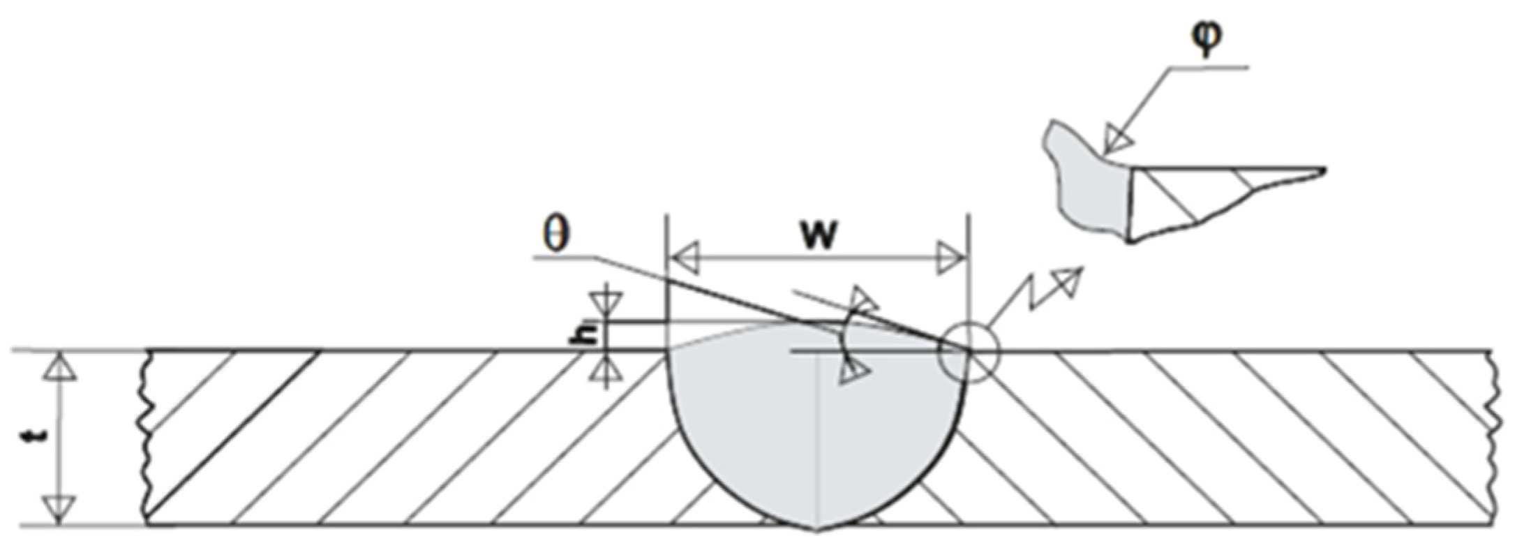
After the welding procedure, 3D sampling was performed [6]. After scanning, samples were loaded into the computer program “GOM inspectors” (GOM GmbH, Braunschweig, Germany), v.2.0.1 and the influential geometric quantities were measured. Figure 1 shows the influential geometric quantities measured using a computer program. The measured values are shown in Table 4.
After all the influential geometric quantities were measured, the stress concentration factor was calculated according to the expression proposed by Ushirokawa and Nakayama [34]. This expression was chosen because it considers all five influential geometric quantities. In addition, this expression has been compared with different ways of calculating stress concentration factors and has proven to be reliable [9].
2.3. The Heat Input Calculation
Welding parameters (electric welding current, arc voltage welding, and welding travel speed) were measured, and the heat input during welding was calculated according to the method described in EN 1011-1 [35]. The coefficient of thermal efficiency was measured according to the EN 1011-1 standard for the MAG welding process and the value of 0.8 was adopted. The calculation was performed using the following formula:
where Q is the heat input (kJ/mm), k is the thermal efficiency, U is the welding arc voltage (V), I is the electric welding current (A), and v is the welding travel speed (mm/s). The heat input results using the arc voltage, welding current, thermal efficiency, and traveling speed are shown in Table 4.
2.4. Proxy for Measurement of Fatigue Cracks
The geometry of the welded joints was analyzed, and the appearance of cracks was expected to appear at the places of increased stress concentration during the long-term exploitation. Since fatigue cracks were not directly observed during the experiment, in this study we used the stress concentration factor as a proxy for the measurement of fatigue cracks, knowing that the stress concentration factor is associated with a higher risk of developing fatigue cracks [36]. The stress concentration factor was determined in accordance with Ushirokawa and Nakayama [34] (Table 4).
3. Results
3.1. Experimental Results
Column (1) in Table 3 shows the run designation; Column (2) shows the position of the additional material during the experiment. Furthermore, Columns 3–6 show the geometric values of the welded joint surface used to calculate the stress concentration factor and Column 7 shows the value of the stress concentration factor according to Ushirokawa and Nakayama [36]. In addition, Columns 8 to 10 show the welding parameters measured during the laboratory test and Column 11 shows the calculated amount of heat introduced into the welded joint. As shown in Column 11, the heat input values ranged from 1700 to 1200 J/mm and from 930 to 560 J/mm. For welded joints made with one end pass, the welding speed is lower and the heat input is higher. Table 4 shows the test results for one replication for all the 24 runs.
3.2. Relationship between Heat Input and Stress Concentration with Respect to the Position of the Additional Material
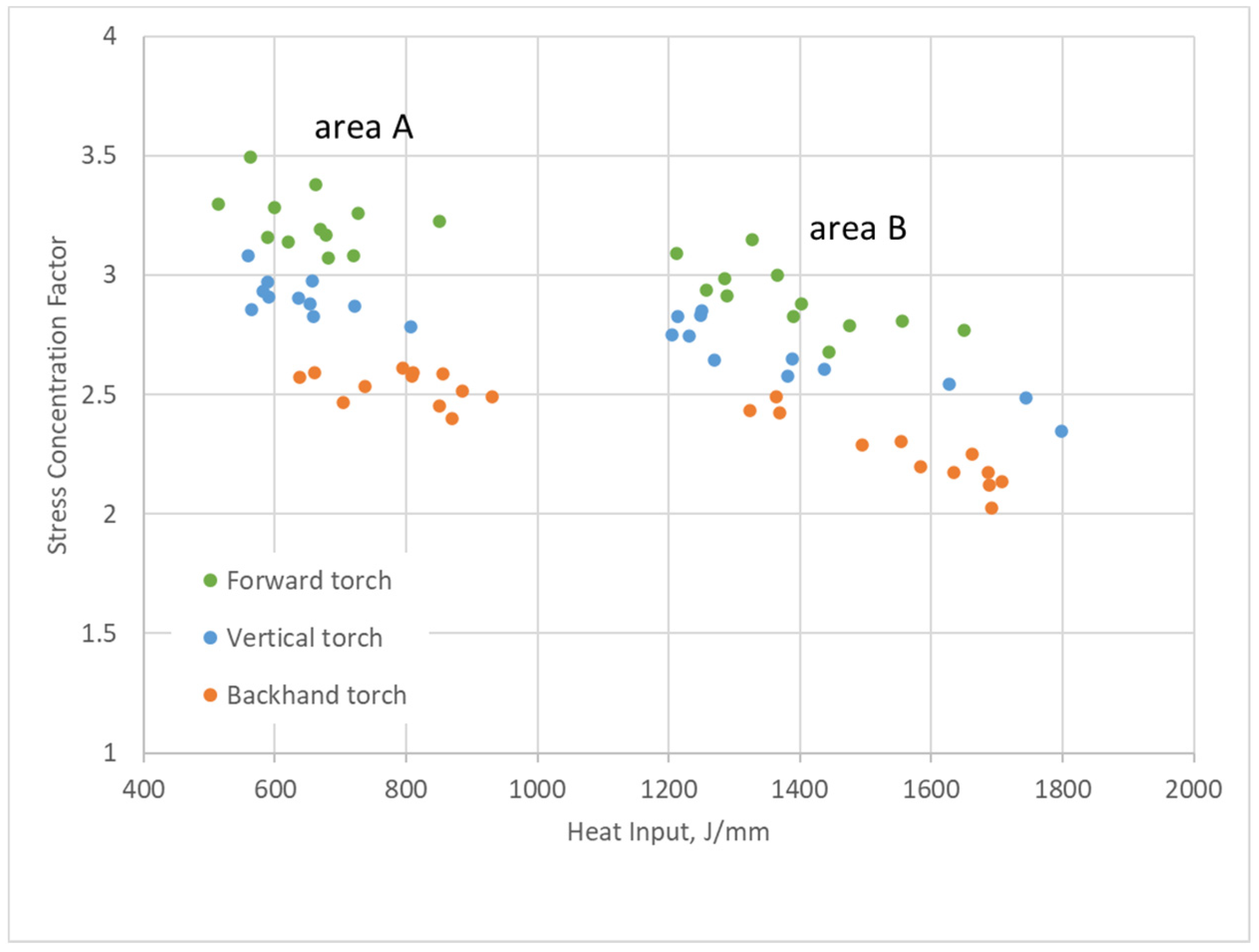
The results were classified into two groups and are shown in Figure 3. The higher heat input was marked in the Figure 3 as area A, while the lower heat was area B. The former resulted in a lower stress concentration factor, increasing the welded joint temperature. The temperature, in turn, increases the time needed for the molten material to solidify and form a good welded joint surface shape. This reduces the stress concentration and the number of cracks occurring during the weld operation.
As noted earlier, experiments were performed using either one or three passes of the final layer. The heat was of a higher input in welds made with one pass due to the lower welding speed. The results were divided into three subgroups (represented by a different color). They were performed using three techniques of depositing weld metal: the forward torch technique (marked in green), the vertical torch technique (blue), and the backhand torch technique (orange). The highest stress concentration was obtained in the forward torch technique mode, while the lowest was detected for the backhand torch technique mode. To sum up, the least surface cracks resulting from the increased stress concentration were created during single-pass welding of the final layer and with the backhand welding technique.
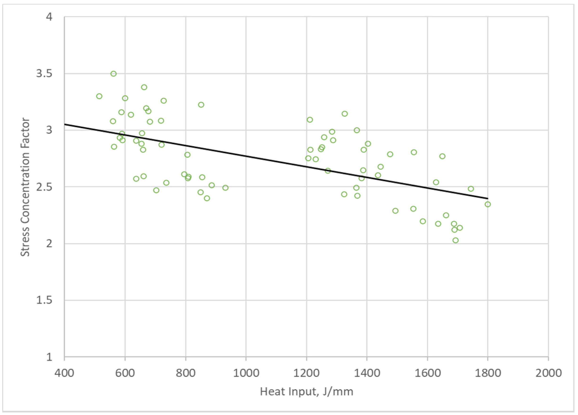
The diagram in Figure 4 shows all the experiments as one set. The decreasing stress concentration trend as the welded joint heat input increases is notable.
4. Discussion
Fatigue cracks initiate on the surface or at internal sites. The initiation event may be associated with slip steps, surface flaws, or defects that increase stress concentrations. Over the past few decades, researchers have investigated the mechanism leading to fatigue failure in welded steel, investing time and energy towards developing a system able to predict service life and reduce the number of structural failures. Our previous study suggested that lowering the stress concentration in the weld face zone might prevent surface cracks in butt-welded joints [6,7]. This study further examined how welding heat input and associated factors can be controlled to minimize the occurrence of fatigue cracks on welded joints. We assumed that no internal defects in the welded joint could cause cracks inside the welded joint.
A number of studies reported the effect of heat on the welding process; however, most were focused on the high-strength steel resistant to low temperatures. In this study, we used steel that requires preheating (at 100 °C) prior to the welding process [37]. During the experiment, three welding techniques were applied: torch angle, number of cover passes, and length of electrode stick-out. In addition, the experiments were carried out in two shielding gas environments: 100% CO2, denoted by “+” and in an air mixture consisting of 82% Ar and 18% CO2 (denoted by “−”). Stress concentration factors and heat input were determined using experimental data that were collected. After the welding procedure, a 3D scan of the welded joint was performed using the most innovative and accurate method [9]. Next, the computer program “GOM inspect” was applied to analyze the geometric data of the welded joint. In addition, the term proposed by Ushirokawa and Nakayama [36] was used to calculate the stress concentration factor. Finally, the stress concentration factor obtained was used to analyze the influence of heat input on the formation of surface cracks.
The stress concentration factor was used as a proxy for analyzing fatigue crack risk. The heat input to the welded joint was calculated according to the recommendations of the European Committee for Standards [34]. The data suggested that heat input is inversely proportional to the stress concentration factor (hence, fatigue crack formation). Therefore, factors affecting heat input should be controlled to minimize the chance of fatigue cracks occurring on welded joints. Such factors include welding current, welding voltage, and welding speed.
The results show that heat input is inversely proportional to the stress concentration factor (Figure 3 and Figure 4). Therefore, if higher heat input is used during welding, there is a relatively low chance of having welded zones associated with high stress. Given that the stress concentration factor is positively related to fatigue cracks, it can therefore be argued that the higher the heat input the lower the chance of welded zones and heat-affected zones experiencing cracking during exploitation. Additionally, given that heat input is directly proportional to arc voltage and arc current and inversely proportional to welding speed, the development of fatigue cracks can be prevented by increasing arc voltage, arc current, reducing welding wire speed, or a combination of all.
The experiments were performed with a very large number of samples to reduce potential bias. The experiments were performed with a welding machine that read the welding parameters. Furthermore, the scanning of the welded joint surface was carried out with the most modern 3D scenario and the measurement of the surface geometric dimensions of the welded joint was performed with an accuracy of 0.01 mm.
The obtained results suggest that higher heat input is associated with a lower risk of surface cracks. This can be explained by higher temperatures of molten material and longer cooling time; thus, the molten material of the welded joint has enough time to form a favorable geometric surface, which leads to a lower stress concentration and thus less risk of initiating surface cracks.
5. Conclusions
The experimental results suggested that higher heat input is associated with lower stress concentration and, therefore, a lower risk of developing fatigue cracks. Higher heat input to the welded joint leads to a greater influence of heat. This further leads to a longer cooling time and the formation of the weld surface, thus giving more time for the molten metal of the welded joint to form a favorable surface of the welded joint, reducing cracks. Thus, it was concluded that the occurrence of fatigue cracks could be minimized by increasing the arc voltage and the arc current or by reducing the welding speed. It should be noted that it is also possible to use a combination of all three. It should also be noted that the upper level of heat input might be limited by the material condition of supply (TMCP, Normalized, QT) and the requirements of minimum average Charpy impact absorbed energy at low temperatures.
In a future study, the authors plan to investigate how much preheating could further reduce the possibility of surface cracks. Furthermore, the heat input that is indirectly related to welding can be increased in the form of increased preheating of the welds before welding. Preheating increases the temperature of the weld and thus forms a weld surface with a lower stress concentration, i.e., a surface in which fewer surface cracks will be created during the exploitation of the welded joint.
Author Contributions
Conceptualization, M.R. and D.P.; methodology, M.R.; software, M.R.; validation, M.R., D.P. and Ž.P.; formal analysis, M.R.; investigation, M.R.; resources, M.R.; data curation, M.R.; writing—original draft preparation, M.R.; writing—review and editing, Ž.P.; visualization, M.R.; supervision, D.P.; project administration, M.R.; funding acquisition, D.P. All authors have read and agreed to the published version of the manuscript.
Funding
This study was supported by the Croatian Science Foundation under project IP-2018-01-3739 and the University of Rijeka (contract nos. uniri-tehnic-18-33 and uniri-tehnic-18-107).
Institutional Review Board Statement
Not applicable.
Informed Consent Statement
Not applicable.
Data Availability Statement
Data are available in a publicly accessible repository.
Conflicts of Interest
The authors declare no conflict of interest.
References
- Fu, Z.; Wang, Y.; Ji, B.; Jiang, F. Effects of multiaxial fatigue on typical details of orthotropic steel bridge deck. Thin-Walled Struct. 2019, 135, 137–146. [Google Scholar] [CrossRef]
- Tsutsumi, S.; Kitamura, T.; Fincato, R. Ductile behaviour of carbon steel for welded structures: Experiments and numerical simulations. J. Constr. Steel Res. 2020, 172, 106185. [Google Scholar] [CrossRef]
- Radaj, D.; Sonsino, C.M.; Fricke, W. Fatigue Assessment of Welded Joints by Local Approaches; Woodhead Publishing Ltd.: Cambridge, UK, 2006; p. 183. [Google Scholar]
- Oliveira, J.; Shen, J.; Zeng, Z.; Park, J.M.; Choi, Y.T.; Schell, N.; Maawad, E.; Zhou, N.; Kim, H.S. Dissimilar laser welding of a CoCrFeMnNi high entropy alloy to 316 stainless steel. Scr. Mater. 2022, 206, 114219. [Google Scholar] [CrossRef]
- Oliveira, J.; Shamsolhodaei, A.; Shen, J.; Lopes, J.; Gonçalves, R.; Ferraz, M.D.B.; Piçarra, L.; Zeng, Z.; Schell, N.; Zhou, N.; et al. Improving the ductility in laser welded joints of CoCrFeMnNi high entropy alloy to 316 stainless steel. Mater. Des. 2022, 219, 110717. [Google Scholar] [CrossRef]
- Lawrence, F.V. Estimation of Fatigue-Crack Propagation Life in Butt Welds. Weld. Res. Supp. 1973, 212–220. [Google Scholar]
- Niemi, E.; Fricke, W.; Maddox, S.J. Fatigue Analysis of Welded Components; Woodhead Publishing Ltd.: Cambridge, UK, 2006. [Google Scholar]
- Randić, M.; Pavletić, D.; Turkalj, G. Multiparametric investigation of welding techniques on toe radius of high strength steel at low-temperature levels using 3D-scanning techniques. Metals 2019, 9, 1355. [Google Scholar] [CrossRef] [Green Version]
- Randić, M.; Pavletić, D.; Fabić, M. Evaluation of the Stress Concentration Factor in Butt Welded Joints: A Comparative Study. Metals 2021, 11, 411. [Google Scholar] [CrossRef]
- Fricke, W. Recent developments and future challenges in fatigue strength assessment of welded joints. Proc. Inst. Mech. Eng. Part C J. Mech. Eng. Sci. 2015, 229, 1224–1239. [Google Scholar] [CrossRef] [Green Version]
- Gandhi, P.; Murthy, D.R.; Raghava, G.; Rao, A.M. Fatigue crack growth in stiffened steel tubular joints in seawater environment. Eng. Struct. 2000, 22, 1390–1401. [Google Scholar] [CrossRef]
- Molski, K.L.; Tarasiuk, P.; Glinka, G. Stress concentration at cruciform welded joints under axial and bending loading modes. Weld. World 2020, 64, 1867–1876. [Google Scholar] [CrossRef]
- Nguyen, T.N.; Wahab, M. A theoretical study of the effect of weld geometry parameters on fatigue crack propagation life. Eng. Fract. Mech. 1995, 51, 1–18. [Google Scholar] [CrossRef]
- Noda, N.; Takase, Y.; Monda, K. Stress concentration factors for shoulder fillets in round and flat bars under various loads. Int. J. Fatigue 1997, 19, 75–84. [Google Scholar] [CrossRef]
- Zappalorto, M.; Lazzarin, P.; Yates, J. Elastic stress distributions for hyperbolic and parabolic notches in round shafts under torsion and uniform antiplane shear loadings. Int. J. Solids Struct. 2008, 45, 4879–4901. [Google Scholar] [CrossRef]
- Oliveira, J.; Miranda, R.; Schell, N.; Fernandes, F.B. High strain and long duration cycling behavior of laser welded NiTi sheets. Int. J. Fatigue 2016, 83, 195–200. [Google Scholar] [CrossRef] [Green Version]
- Wang, Y.; Luo, Y.; Tsutsumi, S. Parametric Formula for Stress Concentration Factor of Fillet Weld Joints with Spline Bead Profile. Materials 2020, 13, 4639. [Google Scholar] [CrossRef]
- Wang, Y.; Fu, Z.; Ge, H.; Ji, B.; Hayakawa, N. Cracking reasons and features of fatigue details in the diaphragm of curved steel box girder. Eng. Struct. 2019, 201, 109767. [Google Scholar] [CrossRef]
- Yao, Y.; Ji, B.; Fu, Z.; Zhou, J.; Wang, Y. Optimization of stop-hole parameters for cracks at diaphragm-to-rib weld in steel bridges. J. Constr. Steel Res. 2019, 162, 105747. [Google Scholar] [CrossRef]
- Fu, Z.; Ji, B.; Kong, X.; Chen, X. Grinding treatment effect on rib-to-roof weld fatigue performance of steel bridge decks. J. Constr. Steel Res. 2017, 129, 163–170. [Google Scholar] [CrossRef]
- Tsutsumi, S.; Fincato, R. Cyclic plasticity model for fatigue with softening behaviour below macroscopic yielding. Mater. Des. 2019, 165, 107573. [Google Scholar] [CrossRef]
- Romanowicz, P.J.; Szybiński, B.; Wygoda, M. Application of DIC Method in the Analysis of Stress Concentration and Plastic Zone Development Problems. Materials 2020, 13, 3460. [Google Scholar] [CrossRef]
- Mao, W.; Ringsberg, J.W. Analysis of fatigue crack initiation and propagation in ship structures. In Proceedings of the 13th International Conference on Fracture, Beijing, China, 16–21 June 2013. [Google Scholar]
- Pavani, P.; Sivasankar, P.; Lokanadham, P.; Uma Mhahesh, P. Finite Element Analysis of Residual Stress in Butt Welding of Two Similar Plates. Int. Res. J. Eng. Technol. 2015, 2, 57–60. [Google Scholar]
- Jeffus, L. Welding: Principles and Applications; Cengage Learning: San Francisco, CA, USA, 2020. [Google Scholar]
- Bytyqi, B.; Osmani, H.; Idrizi, F. Influence of Welding Parameters on Seam Welded Quality with MAG Welding; Strojarski Fakultet: Priština, Kosovo, 2005. [Google Scholar]
- Tewari, S.; Gupta, A.; Prakash, J. Effect of welding parameters on the weldability of material. Int. J. Eng. Sci. Technol. 2010, 2, 512–516. [Google Scholar]
- Yi, H.-J.; Lee, Y.-J.; Kim, J.-Y.; Kang, S.-S. Effect of microstructure and chemical composition on cold crack susceptibility of high-strength weld metal. J. Mech. Sci. Technol. 2011, 25, 2185–2193. [Google Scholar] [CrossRef]
- Steppan, E.; Mente, T.; Böllinghaus, T. Numerical investigations on cold cracking avoidance in fillet welds of high-strength steels. Weld. World 2013, 57, 359–371. [Google Scholar] [CrossRef]
- den Ouden, G.; Hermans, M. Welding Technology., 1st ed.; VSSD: Delft, The Netherlands, 2009; p. 152. ISBN 978-90-6562-206-8. [Google Scholar]
- Det Norske Veritas Germanischer Lloyd. Rules for Classification: Ships. Part 2 Materials and Welding, Chapter 2, Metallic Materials; DNVGL: Hovik, Norway, 2015. [Google Scholar]
- Dalmont Limited. Welding Procedures Specification, Nos D014 & D015; Dalmont: Rijeka, Croatia, 2016. [Google Scholar]
- Vitkovice Steel Limited. Inspection Certificate 3.2; Vitkovice Steel: Vitkovice, Czech Republic, 2011. [Google Scholar]
- Ida, K.; Uemura, T. Stress Concentration Factor Formulae Widely Used in Japan. Fatigue Fract. Eng. Mater. Struct. 1996, 19, 779–786. [Google Scholar] [CrossRef]
- European Standard EN1011-1:2009; Welding—Recommendations for Welding of Metallic Materials, Part 1: General Guidance for Arc Welding. European Committee for Standards: Brussels, Belgium, 2009.
- Kannengiesser, T.; Boellinghaus, T. Cold cracking tests—An overview of present technologies and applications. Weld. World 2013, 57, 3–37. [Google Scholar] [CrossRef]
- Yurioka, N.; Kasuya, T. A Chat Method to Determine Necessary Preheat Temperature in Steel Welding. Q. J. Jpn. Weld. Soc. 1995, 13, 347–357. [Google Scholar] [CrossRef] [Green Version]
Figure 1.
Influential geometric quantities of the butt-welded joint [8].
Figure 1.
Influential geometric quantities of the butt-welded joint [8].

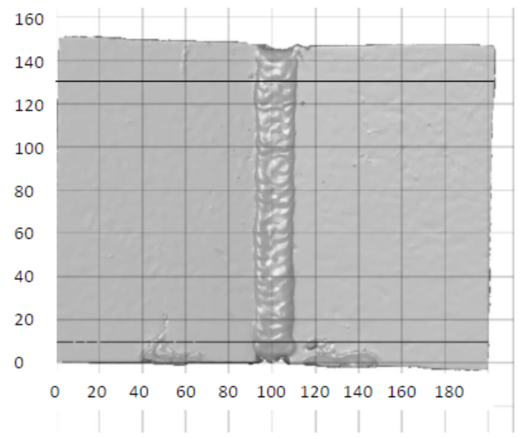
Figure 2.
Sample shown in GOM inspect [9].
Figure 2.
Sample shown in GOM inspect [9].

Figure 3.
Influence of welding technique and heat input on the stress concentration factor of the welded joint.
Figure 3.
Influence of welding technique and heat input on the stress concentration factor of the welded joint.

Figure 4.
Relationship between the amount of heat input to the welded joint and the stress concentration.
Figure 4.
Relationship between the amount of heat input to the welded joint and the stress concentration.


Table 1.
Chemical composition of the base material used in the study.
| Chemical Element (%) | C | Si | Mn | P | S | Cr | Mo | Ni | Al | Cu | Nb |
|---|---|---|---|---|---|---|---|---|---|---|---|
| Required (according to DNV GL Rules) [28] | ≤0.18 | ≤0.50 | 0.90–1.60 | ≤0.035 | ≤0035 | ≤0.20 | ≤0.08 | ≤0.40 | ≥0.020 | ≤0.35 | 0.02–0.05 |
| Actual (according to factory certificate) [30] | 0.176 | 0.34 | 1.42 | 0.014 | 0.001 | 0.050 | 0.003 | 0.020 | 0.024 | 0.020 | 0.026 |
Table 2.
Welding techniques used in the study.
| Welding Techniques | Level | ||
|---|---|---|---|
| Lower (Mark “−”) | Middle (Mark “0”) | Higher (Mark “+”) | |
| Torch angle (A) | Forehand technique Group A | Vertical technique Group B | Backhand technique Group C |
| Number of cover passes (B) | 1 pass | 3 passes | |
| Length of electrode stick-out (C) | 5 mm | 15 mm | |
| Shielding gas (D) | 82% Ar + 18% CO2 | 100% CO2 | |
Table 3.
Summary of the experimental design.
| Input Factor | The Experiment Group and Label Level of Input Factor | |||||||||||||||||||||||
|---|---|---|---|---|---|---|---|---|---|---|---|---|---|---|---|---|---|---|---|---|---|---|---|---|
| A1 | A2 | A3 | A4 | A5 | A6 | A7 | A8 | B1 | B2 | B3 | B4 | B5 | B6 | B7 | B8 | C1 | C2 | C3 | CC4 | C5 | C6 | C7 | C8 | |
| Torch angle | − | − | − | − | − | − | − | − | 0 | 0 | 0 | 0 | 0 | 0 | 0 | 0 | + | + | + | + | + | + | + | + |
| Number of cover passes | − | − | − | − | + | + | + | + | − | − | − | − | + | + | + | + | − | − | − | − | + | + | + | + |
| Length of electrode stick-out | − | − | + | + | − | − | + | + | − | − | + | + | − | − | + | + | − | − | + | + | − | − | + | + |
| Shielding gas | − | + | − | + | − | + | − | + | − | + | − | + | − | + | − | + | − | + | − | + | − | + | − | + |
Table 4.
Experimental results.
| Torch Angle | Geometrical Parameters of Weld Surface | Stress Concentration Factor by Ushirokawa Nakayama | Welding Parameters during the Experiment | Heat Input, J/mm | ||||||
|---|---|---|---|---|---|---|---|---|---|---|
| Toe Radius, mm | Weld Toe Angle, ° | Weld Width, mm | Reinforcement Height, mm | Welding Electric Current, A | Welding Electric Voltage, V | Welding Travel Speed, mm/sec | ||||
| 1 | 2 | 3 | 4 | 5 | 6 | 7 | 8 | 9 | 10 | 11 |
| A1 | Forehand | 0.22 | 45.74 | 20.60 | 2.16 | 3.00 | 261.0 | 23.61 | 3.61 | 1365 |
| A2 | 0.27 | 32.08 | 19.81 | 2.81 | 2.68 | 278.4 | 28.21 | 4.35 | 1444 | |
| A3 | 0.27 | 44.68 | 18.86 | 1.90 | 2.91 | 212.2 | 24.36 | 3.21 | 1288 | |
| A4 | 0.30 | 29.96 | 22.73 | 1.31 | 2.37 | 236.0 | 28.83 | 3.30 | 1649 | |
| A5 | 0.20 | 43.31 | 28.66 | 2.34 | 3.25 | 257.1 | 23.68 | 6.70 | 726 | |
| A6 | 0.43 | 26.69 | 27.11 | 1.99 | 2.17 | 272.1 | 28.30 | 9.10 | 677 | |
| A7 | 0.22 | 50.15 | 24.57 | 3.01 | 3.49 | 218.1 | 24.30 | 7.54 | 562 | |
| A8 | 0.36 | 31.45 | 27.43 | 1.56 | 2.08 | 229.8 | 28.92 | 7.39 | 719 | |
| B1 | Backhand | 0.29 | 49.93 | 21.69 | 1.77 | 2.84 | 254.9 | 23.74 | 3.87 | 1250 |
| B2 | 0.27 | 42.31 | 25.40 | 1.92 | 2.65 | 266.5 | 28.35 | 3.36 | 1798 | |
| B3 | 0.33 | 47.01 | 20.19 | 1.62 | 2.75 | 212.3 | 24.42 | 3.44 | 1205 | |
| B4 | 0.29 | 41.96 | 21.79 | 2.63 | 3.10 | 219.8 | 29.00 | 3.55 | 1436 | |
| B5 | 0.39 | 30.60 | 25.62 | 1.41 | 2.13 | 242.3 | 23.97 | 7.98 | 582 | |
| B6 | 0.28 | 29.48 | 26.61 | 1.75 | 2.57 | 291.7 | 28.28 | 9.15 | 721 | |
| B7 | 0.27 | 45.46 | 23.27 | 2.73 | 3.37 | 195.9 | 24.62 | 6.55 | 589 | |
| B8 | 0.26 | 36.10 | 24.23 | 2.39 | 2.98 | 222.1 | 28.99 | 7.85 | 656 | |
| C1 | Vertical | 0.47 | 31.24 | 22.69 | 1.86 | 2.14 | 252.9 | 23.79 | 2.82 | 1706 |
| C2 | 0.38 | 30.92 | 20.98 | 1.07 | 2.03 | 282.0 | 28.13 | 3.75 | 1692 | |
| C3 | 0.37 | 41.53 | 19.06 | 2.47 | 2.72 | 234.1 | 24.40 | 3.34 | 1251 | |
| C4 | 0.30 | 35.35 | 20.42 | 1.70 | 2.49 | 225.5 | 28.97 | 3.3 | 1368 | |
| C5 | 0.28 | 32.41 | 20.46 | 1.70 | 2.59 | 241.2 | 23.93 | 5.4 | 855 | |
| C6 | 0.31 | 29.33 | 31.32 | 1.61 | 2.20 | 269.0 | 28.34 | 7.01 | 870 | |
| C7 | 0.26 | 47.61 | 26.10 | 3.63 | 3.21 | 197.6 | 24.48 | 4.37 | 885 | |
| C8 | 0.35 | 50.70 | 27.16 | 3.09 | 2.99 | 211.9 | 29.11 | 5.30 | 931 | |
Publisher’s Note: MDPI stays neutral with regard to jurisdictional claims in published maps and institutional affiliations. |
© 2022 by the authors. Licensee MDPI, Basel, Switzerland. This article is an open access article distributed under the terms and conditions of the Creative Commons Attribution (CC BY) license (https://creativecommons.org/licenses/by/4.0/).
Share and Cite
MDPI and ACS Style
Randić, M.; Pavletić, D.; Potkonjak, Ž. The Influence of Heat Input on the Formation of Fatigue Cracks for High-Strength Steels Resistant to Low Temperatures. Metals 2022, 12, 929. https://doi.org/10.3390/met12060929
AMA Style
Randić M, Pavletić D, Potkonjak Ž. The Influence of Heat Input on the Formation of Fatigue Cracks for High-Strength Steels Resistant to Low Temperatures. Metals. 2022; 12(6):929. https://doi.org/10.3390/met12060929
Chicago/Turabian StyleRandić, Miroslav, Duško Pavletić, and Željko Potkonjak. 2022. "The Influence of Heat Input on the Formation of Fatigue Cracks for High-Strength Steels Resistant to Low Temperatures" Metals 12, no. 6: 929. https://doi.org/10.3390/met12060929
Note that from the first issue of 2016, this journal uses article numbers instead of page numbers. See further details here.