1. Introduction
Continuous casting practices for steelmaking have been constantly evolving ever since the early 1930s, when Junghans was first researching ways to pour liquid steel into an open-bottomed, water-cooled mold, to withdraw the partially solidified steel out of it, continuously, in the form of a round or square billet or slab [
1,
2]. He envisioned that once these continuously cast shapes had become fully frozen, their solidified ends could be cut off for further processing. In this way, they could be transformed into “rebar” to reinforce concrete, or into bars from which nails, bolts, tire cord wire, etc., could be fashioned, etc. Reference 1, edited by Dr. Manfred Rasch, contains detailed articles from many of the key companies, personnel, and timelines of events in his review of the development of continuous casting practices for steel, beginning with Sir Henry Bessemer (1813–1898), and followed by Siegfried Junghans (1887–1954).
Thus, the underlying goal of Junghans’ early research was to try to replace the static mold ingot casting systems used in virtually all steel plants up until the 1960s with a continuous process. This would effectively eliminate the ~10–20% losses associated with the “top and tailing” of the thick ingots (up to ~30, or 760 mm) typically being produced. Thus, after the cast ingots had cooled sufficiently (~5 h), to allow them to be safely withdrawn from their ingot molds, they were sent, still partially molten inside, to the soaking pits for temperature homogenization. This could last from approximately 10 h for a hot ingot, or up to 18 h for a cold, ingot. During this treatment time, the micro-segregation of solute elements (C, S, P, Mn, etc.) could be mitigated within the inter-dendritic solidification structure. In the meantime, temperature profiles within the ingot had become uniform, to ~±2 °C, ready for rolling down to semi-finished products. Thus, after proper soaking, the eight or more ingots within the soaking pit would be ready for transfer to the adjacent hot mill for rolling into “flat” or “long” products at temperatures of around 1100 °C.
First, the ingots were sent to the “roughing mill” for ingot “break down”. This was accomplished by passing them back and forth under the roughing mill, thereby transforming the original 25–30 inch thick ingot (635–760 mm) into a long, 1–2” (25–50 mm) thick “transfer bar”. This bar then had to be “topped” and “tailed”’ to eliminate the rolled-in surfaces at the transfer bar’s extremities, where surface overlap had occurred during compression and thickness reduction to 30 mm or ~2–3 inches. Similarly, any macroscopic shrinkage holes formed during solidification also needed topping before sending the transfer bar to the stands of the rolling mill. All of this automatically led to a mandatory 10–15% loss in yield.
Therefore, for sheet steel products, following a further removal of iron oxide skin from the transfer bars using high velocity, high pressure water jets just ahead of a six- or seven-stand hot rolling mill, the transfer bars were reduced to much thinner hot rolled steel sheet products, ~1–3 mm thick, using appropriate cooling schedules to create the specific hot grades being targeted (e.g., HSLA, etc.).
Clearly, Junghans’ research, which lead to the Conventional Continuous Casting (CCC) method, promised to eliminate much of the material losses associated with the ingot casting approach, and thereby produce a step-up increase in steel productivity.
However, approximately seventy-odd years before Junghans’ early research work, Henry Bessemer, inventor of the first tonnage steel process, had proposed a far more elegant process to cast liquid steel into near-net shape products, namely the Twin Roll Casting (TRC) process. He envisioned pouring liquid steel into the cavity produced by a twin set of contra-rotating rolls to freeze the exiting steel directly into ~1–2 mm thick sheet steel products. Following minimal rolling and heat treatment, this would be ready for sale. While many researchers had since tried to fulfill Bessemer’s twin-roll casting “dream” and produce a commercial system for thin steel sheet production over the ensuing century before Junghans’ research work, none had succeeded in producing high-quality sheets of steel.
We make mention of Clarence Hazelett, founder of the Hazelett Strip Casting Company, U.S.A, who had been researching Bessemer’s Twin Roll Caster concepts (TRC) in the early 1930s for non-ferrous systems. He had some success but finally decided to abandon that approach in favor of a Twin Belt Caster (TBC) moving mold system in 1949.
His TBC system was approximately ten times more productive and proved to be a commercial success for copper, lead and zinc alloys, and certain grades of aluminum and magnesium alloys. TBC casters are now in worldwide use within the non-ferrous industry, but not for casting liquid steel. Previous attempts by Hazelett Strip Casting Corp., in collaboration with Sumitomo Metals Corporation, and earlier with U.S Steel/Bethlehem Steel in the 1980s, had failed to develop a satisfactory commercial system for the steel industry.
Therefore, today, the dominant casting process within the steel industry is the Conventional Continuous Caster (CCC), as developed by Rossi and partners with their CONCAST Corporations in Europe and the USA, following Junghans’ death and Rossi’s sole acquisition of patent rights from Junghans’ widow [
1,
2].
2. The Past
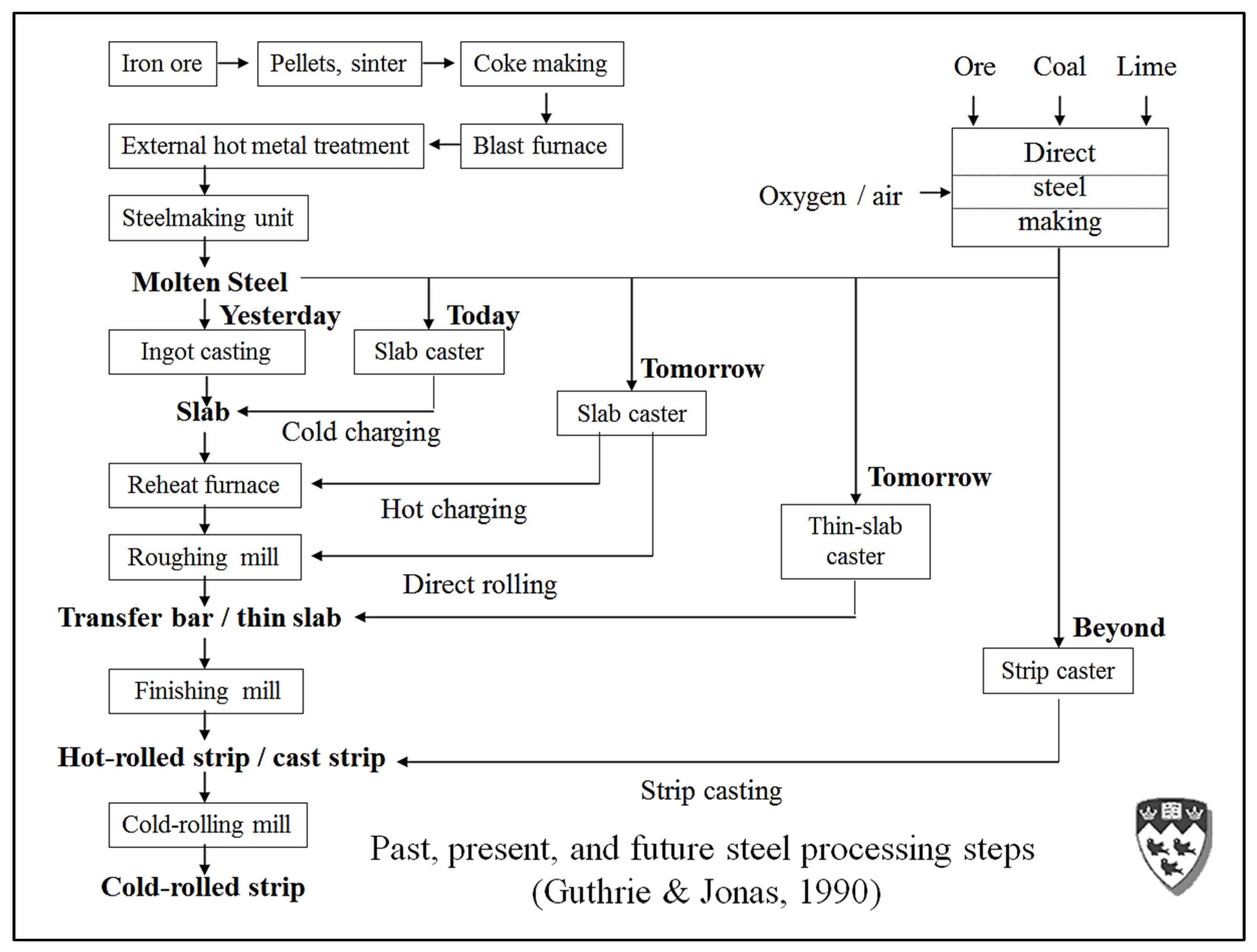
Thus, thanks to the initial research efforts and work carried out by Siegfried Junghans (1887–1954) in Germany, aimed at eliminating the wastage caused by the ingot casting process, a disruptive paradigm was brought to the steel industry. Thus,
Figure 1 illustrates the evolutionary sweep in continuous casting developments ever since that seismic change from ingot casting technologies to CCC [
3]. It began in the 1950s, following the first designs of continuous casting machines by CONCAST. These casters were developed in collaboration with some early companies and their dedicated researchers, who recognized the important economic implications deriving from this new type of casting machine [
1]. For the fixed CCC approach, the formulations for mold powders are important for protecting the surface of molten steel from significant heat losses and by remaining molten at ~900 °C to provide lubrication between the surface of the forming slab and the oscillating walls of the copper mold.
A key role in the development of the continuous casting method was played by Iain Halliday at Barrow Steel Works, in Scotland. He perfected the Junghans–Rossi oscillation mode (i.e., three-quarters of the cycle down and one quarter up), by imposing a relative velocity during the down-stroke, with the mold going down slightly faster than the strand, which he termed “negative strip”. This invention helped to resolve the sticking of the growing frozen steel shell onto the copper mold and allowed him to reach casting speeds of 14.5 m/min in 1958. This casting speed is still a world record for these “fixed or stationary” mold technologies. Conventional continuous casting machines, nearing process perfection in recent years, allow partially solidified slabs, blooms, or billets, to be continuously withdrawn through their open-bottomed molds, at productivity levels equivalent to ingot casting technology, but with a 10–15% yield advantage. Some 1.8 billion tons per year are now cast through them.
Thus, the growing steel industries in Japan and Korea in the 1960s, as well as the well-established companies in the Nordic countries, were the first to adopt this new way of casting. Asian countries went on to become dominant global players in CCC, exporting much of their steel abroad, including to North America. Meantime, many conventional integrated steel plants in North America gradually walked into bankruptcy, some even before being able to adopt this new technology. For example, Dofasco escaped by the skin of its teeth thanks to the warnings and the advice of Dr. Dante Cosma of their Research Department to the President of the Company, Mr. Frank Sherman. He heeded Dante’s advice over that of all the other “experts” within his company and canceled the new ingot casting aisle midway through construction. Nonetheless, approximately ten years later, Dofasco could not escape the clutches of ArcelorMittal (AM) in the “race to the bottom” at the start of the second millennium. This take-over seems to have been achieved by selling off Dofasco’s valuable iron ore mines in Ontario and Quebec after having first acquired the company, thereby allowing AM to cover its initial expense for Dofasco’s acquisition. Naturally, the Board of Directors of Dofasco had already been handsomely rewarded in the original sale of the company.
Nonetheless, and fortunately for North America, the mini-mill concept and its first implementation in the new steelmaking plant built in Oshawa, Ontario, had been confirmed by Dr. Gerald Heffernan and his co-workers in ~1985 [
2]. This had been followed a couple or so years later by a succession of NUCOR plants being built in the countryside of the USA; as a new revolution in North America (N.A.), steelmaking practices began to take shape [
2]. As such, many newer plants in N.A. have shifted away from the conventional blast furnace-BOF steelmaking model towards a 100% scrap-melting/continuous casting technology. Many of the recent continuous casting technologies now presented, were researched by the conventional integrated steel companies, but were brought into the steel industry through efforts by Minimills to invade the more lucrative niches for steel production. Nevertheless, to the authors’ knowledge, all the steel sheet products used for “body in white” automobiles remain within the exclusive domain of advanced CCC steel plants around the world.
3. The Present (2020s)
Referring to
Figure 1, the left-hand side of the diagram shows the situation before the advent of continuous casting in the mid-1950s. North America’s first commercially successful vertical mold continuous casting machine was commissioned in 1954 to produce slabs of stainless steel at the Welland Plant of Atlas Steels in Ontario, Canada, using a “stick caster”. Today, all ingot casting has been eliminated worldwide, apart from some specialty steel applications.
For this new paradigm in casting technology, yield increases of approximately 10–15% have been achieved thanks to the successful development of slag-lubricated, oscillating, open-ended mold machines. These molds, and the behavior of their mold fluxes, are at the very heart of the various continuous casting machines dominating steel casting processes.
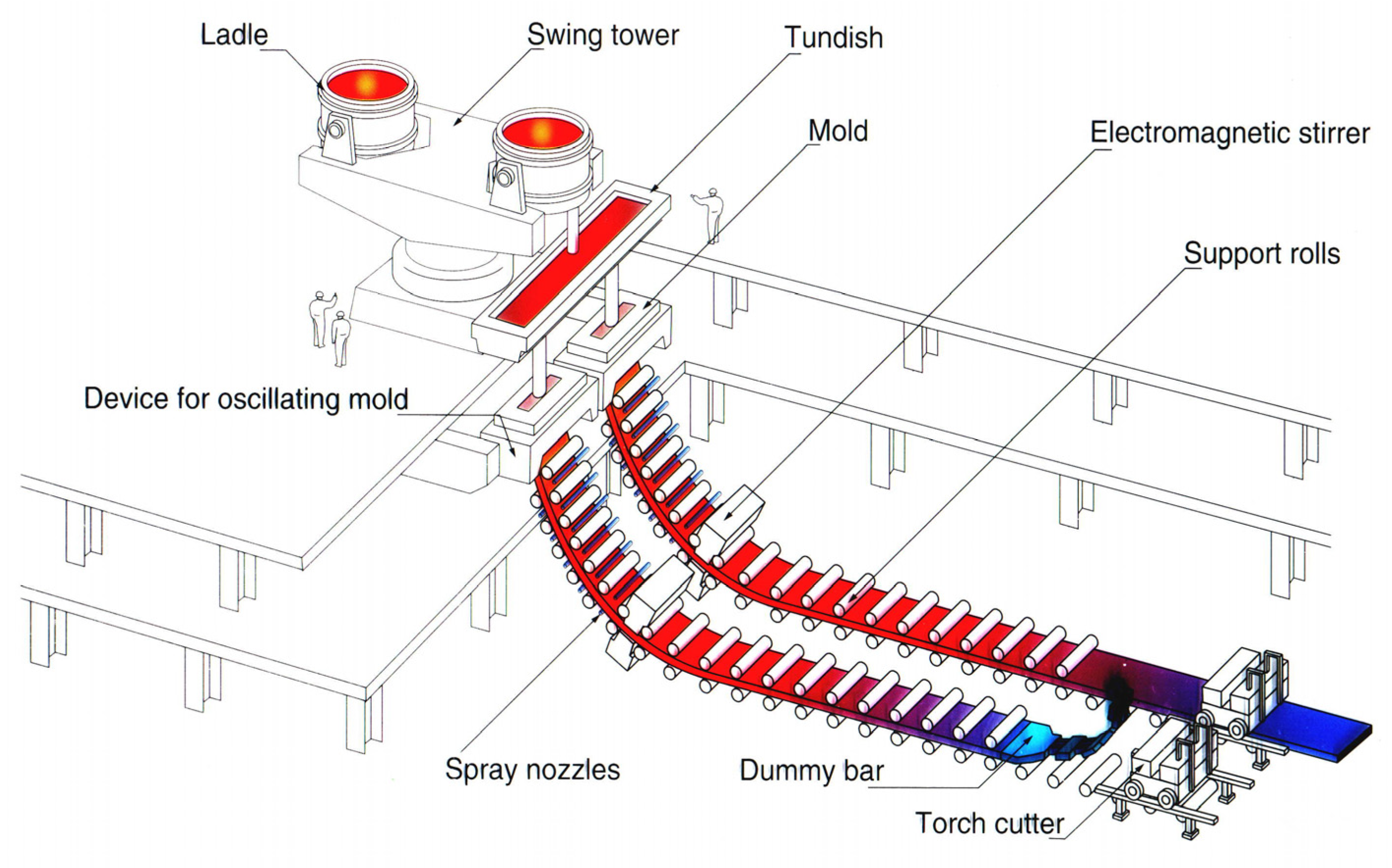
Figure 2 shows a conventional continuous casting operation comprising a tundish, a water-cooled, chromium-plated, copper alloy mold, a mold oscillator, a group of cast strand supporting rolls, rolls for bending and straightening the strand, rolls to pinch and withdraw the cast strands, groups of water spray nozzles to extract heat from the strand, a torch cutter for cutting the cast strand, and a dummy bar [
4]. This dummy bar fits in the bottom of the open mold at start-up, providing a starting base on which the strand can freeze. The dummy bar then extracts the cast strand, and finally moves away to “storage” once the forming strand has approached the torch cutter.
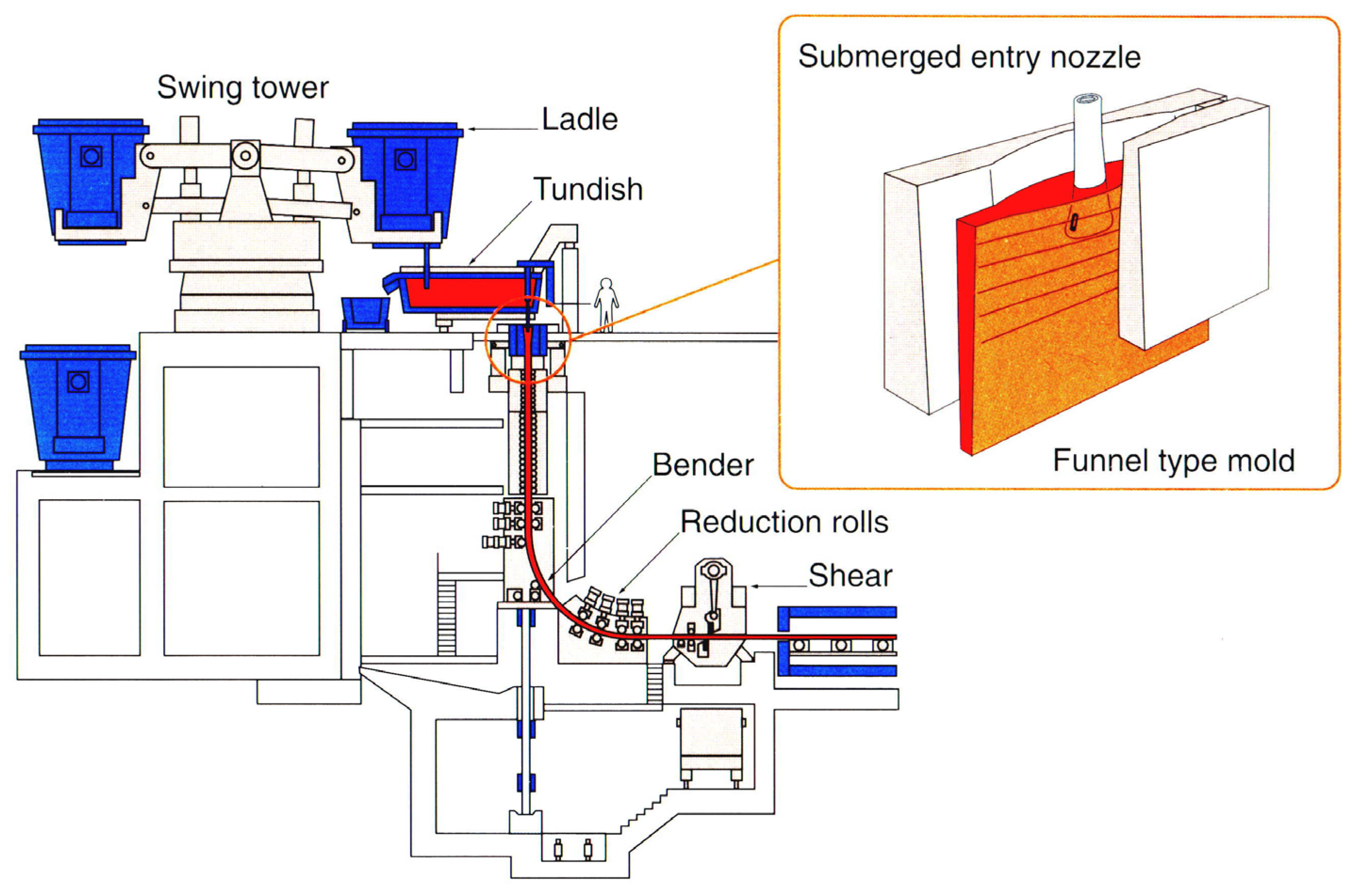
The overall set-up is generic, in that a “ladle” sits on a rotating “turret” or “swing tower” and empties liquid steel into a “tundish” set below via a protective ladle shroud (or tube). This tundish is used to distribute metal to one, two, four, six, or even eight oscillating molds/strands, set below. In the case of slab casting operations, it is common to have twin slab production. In the diagram, a SEN(Submerged Entry Nozzle) is used to protect the streams entering the mold from re-oxidation. Once the ladle has been emptied of steel, the tundish is allowed to drain while the turret rotates a newly filled ladle into position. In this way, “sequence”, or “continuous, continuous” casting can be achieved, with uninterrupted runs in the order of up to 1000 ladle changes being possible, using the flying tundish technique for the rapid replacement of a spent tundish.
Another popular type of fixed-mold conventional continuous caster is the “vertical, curved mold”-type caster, in which, the mold and support rolls are arranged vertically to maximize the chances for inclusions to float out of the deep sump of molten steel before being trapped in the solidifying shell. The strand is then bent and straightened to deliver the strand horizontally, and continuously. In comparison, the first “stick”, or vertical mold casters, froze single vertical strands in the same way as today’s DC (Direct Chill) casters for the aluminum industry. The fact that curved mold and low-head curved mold machines tend to capture a band of inclusions approximately mid-distance from the top surface of the strand, and its central axial plane, led to the popularity of the vertical-curved bending machine. In technically advanced steel mills, where surface quality is good (freedom from scabs, slivers, and deep oscillation marks), these slabs, blooms, and billets can be hot charged directly to a reheat furnace without surface inspection before further size reduction.
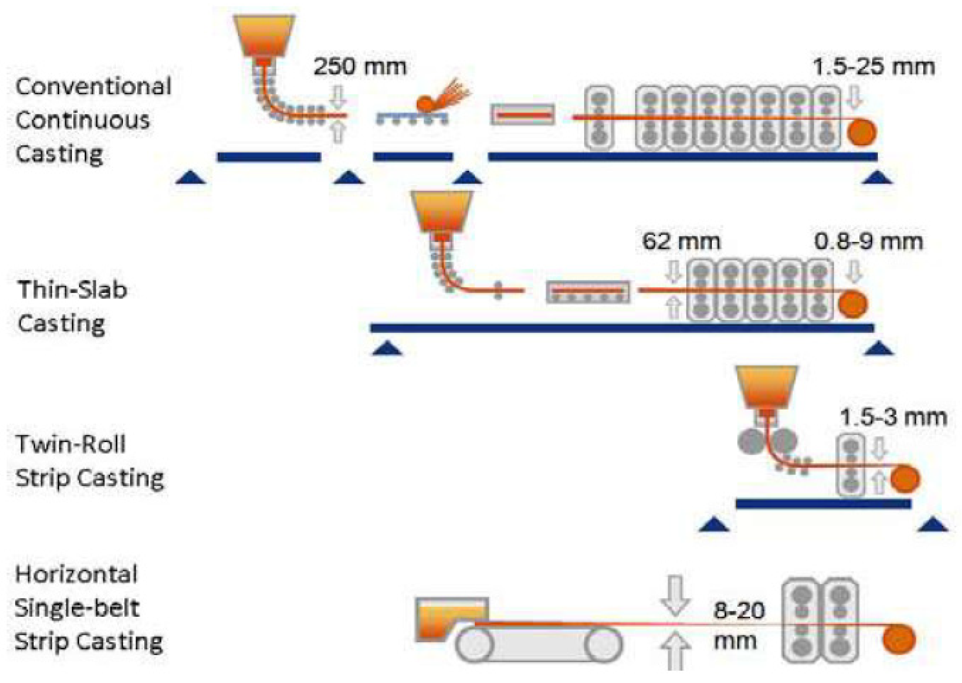
However, a certain amount of scale (iron oxides) will usually form on the slab’s surfaces during their time in the reheating furnace. This can be useful in moderation since surface blemishes can then be removed during passage through the high-powered water jets of the de-scaler. In the case of slabs for sheet products, a roughing mill then rolls the slab down to a “transfer bar” some 25–50 mm (1–2 ins) thick. In most current commercial operations for sheet production in integrated steel plants, the transfer bar is then fed into a six- or seven-stand hot strip mill, where a steel sheet, 1–4 mm thick, is produced at speeds approaching 15 m/s (3000 ft/min). Strip temperatures, alloy compositions, and rates of compression are all carefully controlled to manipulate the solid-state phase transformations and thereby optimize steel microstructures and attendant mechanical properties. Since the early adoption of CCC machines by the large integrated steel mills, there has been considerable pressure on reducing the capital and running costs of these mammoth steel plants. The first development in the commercial continuous casting of steel was the Thin Slab Caster (TSC) in 1985 [
1]. These casting machines, illustrated in
Figure 3, are aimed at servicing the rapidly growing EAF-based mini-mills in North America, thereby allowing them to enter the lucrative sheet metal market.
5. NNSC Moving Mould Technologies
Meanwhile, as noted previously, ever since the 1880s, there have been many efforts to fulfill the dream of Sir Henry Bessemer to cast steel strips directly from a pool of liquid steel using twin-roll casting technologies. Various consortia and companies have researched the characteristics and potential of such Near Net Shape Casting (NNSC) machines. In 2000 AD, Nippon Steel and Mitsubishi Heavy Industries announced the world’s first commercial operation of a Twin Roll Caster (TRC) to produce sheets of stainless steel, 2–5 mm thick, 0.76–1.3 m wide, at their Hikari Works in Southern Japan. The roll diameters were approximately 1.2 m, and peripheral roll speeds were in the order of 1 m/s. A pinch roll gathered the strip, which, following minimal hot working, was cooled and coiled directly into the finished product. However, following the second rebuild of their caster, they abandoned their commercial TRC system, quoting “unresolved microstructures” and an uneconomical performance. Similar events occurred in Europe, where the Euro-strip caster, a TRC development, was abandoned without explanation following many years of apparently very promising research work.
Nonetheless, and contrary to those decisions, following initial research work by BHP in Australia to prove the viability of their TRC process in Melbourne, CASTRIP (NUCOR/BHP/IHI) was incorporated, and a commercial twin roll caster was built by IHI to produce low carbon steel strips at NUCOR’s Crawfordsville Plant. The building of this commercial strip caster for producing low carbon steel sheet material, 1.7–1.9 mm thick, was announced in 2002 [
7]. The NUCOR casters rolls are only 0.5 m in diameter, much the same as in Bessemer’s original patent specifications, and run at speeds of 1–2 m/s during casting. Furthermore, the plant continues to operate ten years later. Therefore, some steelmakers have finally realized Bessemer’s visionary intuition and achieved the long sought-after rationalization of downstream processing of steel. A second machine was built for NUCOR, and plans have been made to install a CSP (Compact Strip Caster) in the UK, and two in the Peoples Republic of China [
8].
However, it is still possible that the economic viability of the TRC process remains in question. Apparently, only two or three consecutive ladles can be cast before a roll change. Apparently, the build-up of frozen steel accretions at the liquid steel/side dam interfaces can open the roll gap settings. This can cause the computer control system to increase the roll separation distance, followed by a “break-out”. As such, more than approximately three consecutive ladles seem to be impractical at present (2020), on average. Nonetheless, other reports claim that a ten-ladle sequence is possible. Similarly, while CASTRIP is ideal for mini-mill operations, there is a fivefold mismatch in the maximum productivity of a twin roll caster vs. current integrated steel manufacturing slab casting operations (e.g., ~400,000 tpy vs. ≥2,000,000 tpy).
Such problems regarding TRC operations, together with some basic thermo-mechanical considerations, led to an alternative solution for integrated mills being proposed by Herbertson and Guthrie in 1987, and independently by Professor Schwerdtfeger et al. a little later that year [
9]. Both groups independently proposed a Horizontal Single Belt Caster (HSBC) approach, which ideally involves using a high speed (1–3 m/s) horizontal single belt, on which, steel is poured, as shown in the bottom casting system of
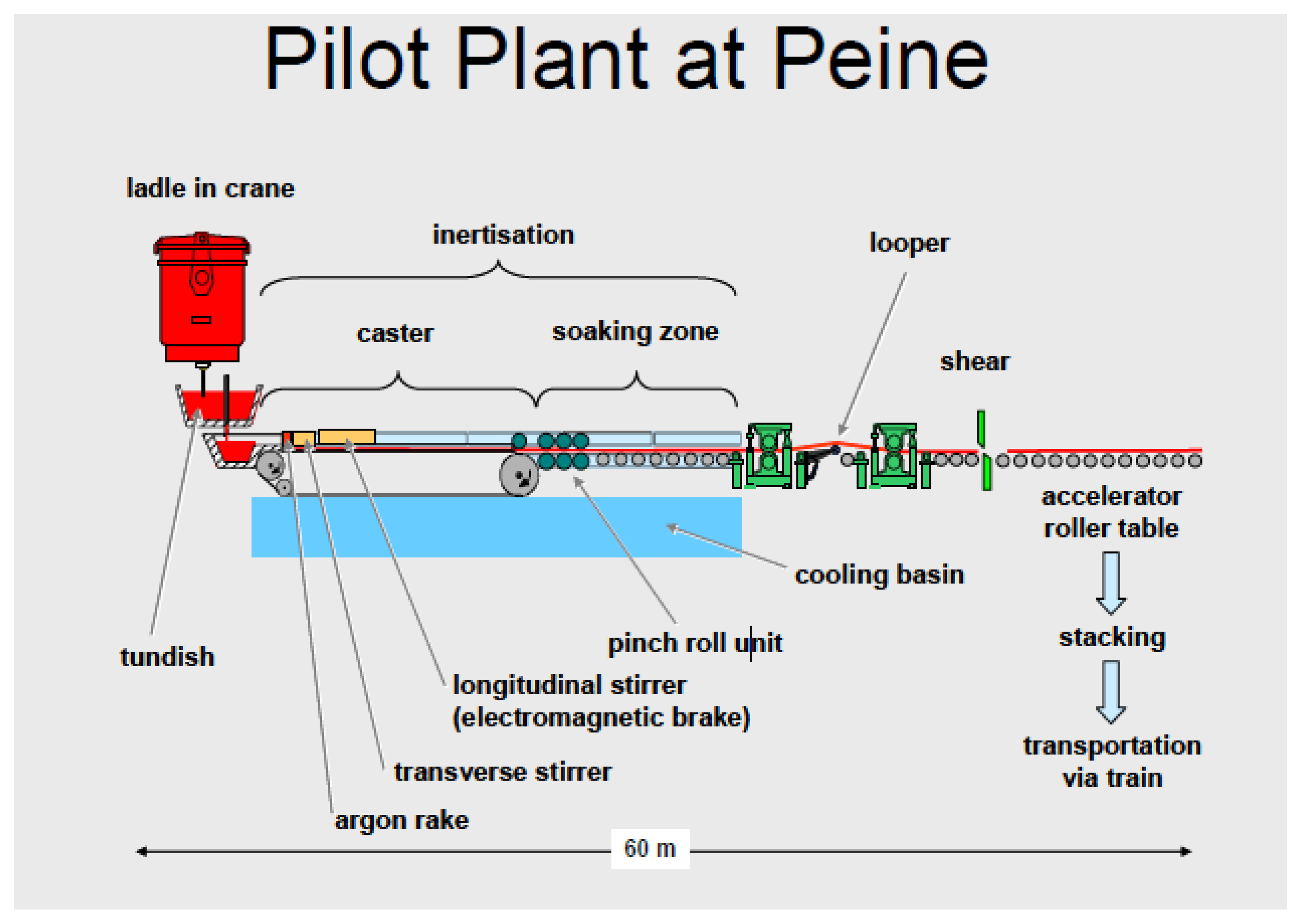
Figure 3. Since then, the world’s first commercial HSBC caster, named Belt Casting Technology (BCT), was designed for producing ~1 MT/year by SMS Demag and was delivered to the Peine plant of Salzgitter. There, casting trials, initially targeting advanced high-strength steels, began in 2012, exploring its potential for casting a variety of novel High-Strength, High-Ductility (HSHD) steels using a 13 m long belt running at ~0.4 m/s [
10]. The plant layout is presented in
Figure 5.
6. The Future
All continuous casting machines involve the freezing of a shell of steel, forming either against a vibrating “stationary”, or against a moving belt, or twin rolls. For the fixed CCC approach, the formulations for mold powders are important for protecting the surface of molten steel from significant heat losses and by remaining molten at ~900 °C to provide lubrication between the surface of the forming slab and copper mold. On that note, one of the key “sticking points” delaying CCC’s successful commercial development in the late 50 s and early 60 s, versus the then conventional ingot casting operation, was the development of the oscillating mold. Typically, the molds for slab, billet, and bloom casting are oscillated in a sinusoidal manner (at 1–3 Hz), and mold powder is fed into the meniscus region, where it gradually melts to form a liquid, lubricating slag. This is needed to prevent the newly formed shell from sticking to the copper mold. The oscillatory motion has also been thought by many to contribute to the feeding of molten slag into the mold/strand gap. Based on comprehensive CFD simulations [
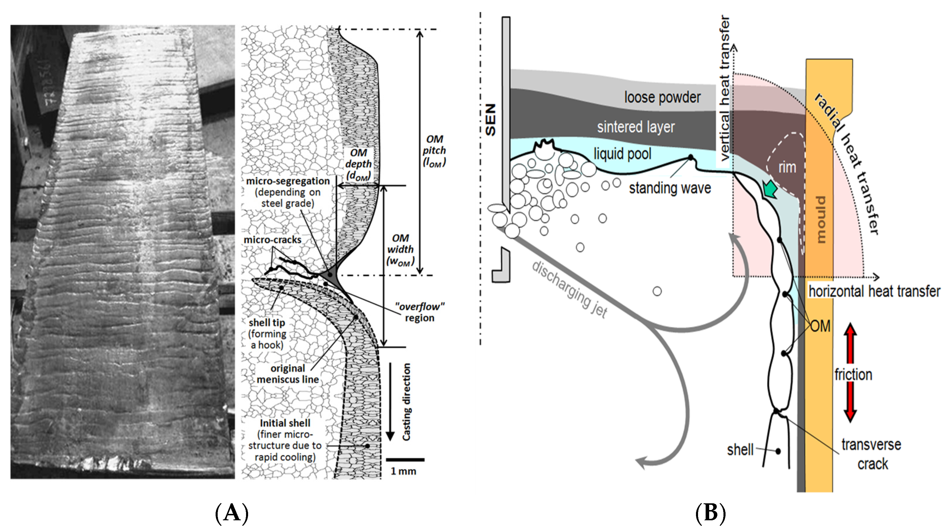
9], this is true. It certainly helps with strand-sticking problems, which lead to thin shells and costly liquid steel “breakouts”. These breakouts of steel can cause the freezing of molten steel onto the caster’s guide rolls, leading to extended downtimes. Nonetheless, the well-known OMs (Oscillation Marks) associated with CCC (Conventional Continuous Casters), and shown in
Figure 6A, caused by these oscillatory motions, represent surface imperfections or defects, their lengths and frequencies being governed by the length and frequency of the stroke. The first moments of solidification modeled in
Figure 6B reveal that the lubricating slag changes the direction of heat transfer from a horizontal direction during the downstroke to a vertical heat flow during the up-stroke when a lower radial rate of heat extraction prevails. This leads to a re-melting of the forming shell. The result is akin to forming a row of linked sausages, as appears in
Figure 6B.
The problem with OMs is that they can also be a source of micro-cracks. However, the “un-acknowledged” saving grace for present CCC and most TSC systems is the later oxidation of the outer layers of a cast steel slab, bloom, or billet in the reheat furnaces or muffle furnaces that can effectively “oxidize away” such discontinuities before rolling operations.
A similar situation occurred in the production of “rimming grade steels” via ingot technology, where subsequent oxidation of its blemished surfaces in the ingot soaking pits would also result in blemish-free final surfaces, ready for rolling down to the thin strip auto-body sheet. Thus, ingot casting techniques for “rimming grade” steels for auto companies in North America were practiced up into the 1980s, when equivalent quality, aluminum-killed (AK) steel grades of CCC sheet material finally became available.
For any NNSC process to be able to compete with the blemish-free surfaces of slabs produced using ideally operating CCC and TSC systems, NNSC surfaces must also be completely free of blemishes. Many of us will know that, at very high speeds of rotation, single roll casters can produce perfect bottom surfaces; for example, when producing ~100 micron thick sheets of metallic glasses (e.g., the MetGlas™ process for producing steel sheets for electrical transformers, containing 1% boron and 4% silicon). Therefore, the only question remaining for a moving mold system to usurp the current technological impasse of poor cast surfaces, is what is the critical lower speed for such a moving mold system? Perhaps it is self-evident that the criteria must be (1) how fast does the substrate have to move, to separate the line of initial freezing from the line of initial contact of the liquid metal with the cooling substrate system, and (2) how can we eliminate the high-frequency oscillations of the back meniscus, where the liquid metal first contacts the cooling belt?
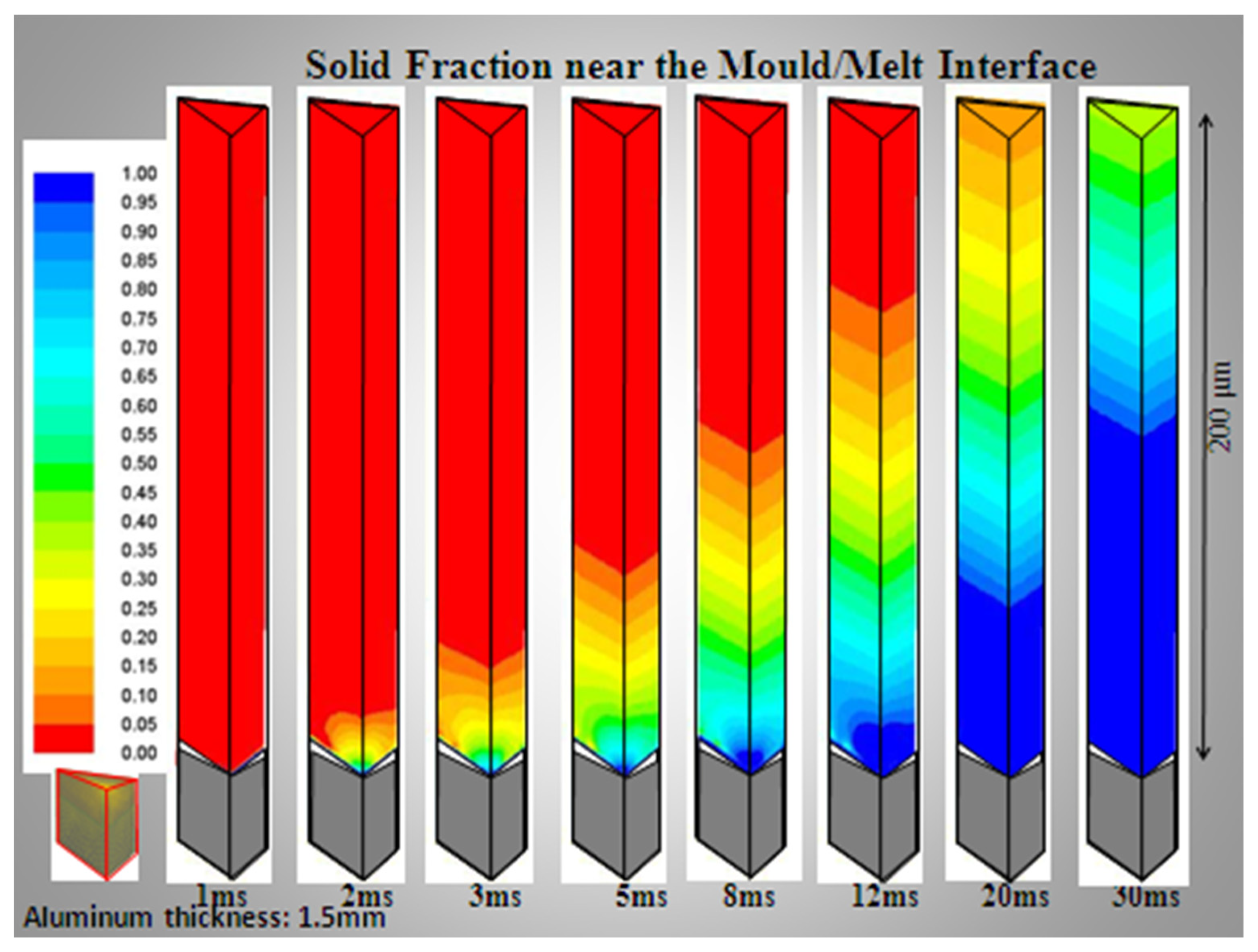
We now refer to experimental work carried out at the McGill Metals Processing Centre (MMPC), some fifteen years ago, in which we were able to measure instantaneous heat fluxes using a strip casting simulator, in which we poured liquid aluminum, and later liquid steel, on to a moving, flat copper substrate, 12 mm thick, moving at ~1 m/s. This simulates equivalent initial heat fluxes and the freezing of molten metal onto a 1 mm thick water-cooled steel belt running at the same speed [
13]. We were able to characterize the topography of the sand-blasted copper surface and then use an equivalent geometrical construct to predict instantaneous heat fluxes for comparison with experimental results. The modeling result is shown in
Figure 7, whose predicted heat fluxes and initial shell formation coincided well with equivalent simulator experiments. Note that the contact is essentially non-wetting, even at the 20–30 µm high peaks of the rectangular pyramids (260 pyramids/mm
2). We must also compensate for sudden gas expansion at the mold-metal interface.
Armed with this knowledge, one sees that one has perhaps 15 ms to make a perfect surface of the AA6111 sheet before any surface imperfections are stamped into the bottom surface of the metallic sheet. Similar results can, and were, computed for steel alloys, based on their thermal properties and those of the substrate and interfacial gases.
Our experiments have demonstrated that perfect bottom surfaces can be attained, as have equivalent tests at Clausthal University, and Salzgitter Steel. The other question of stabilizing the initial contact of liquid metal onto the cooling mold has also been considered, and we believe that this meniscus line can be held steady, thereby eliminating the so-called chatter marks reported for TRC operations at NUCOR.
Thus, the final question for opting to replace standard CCC processes with far less expensive (capital and operating costs) and far more environmentally friendly NNSC processes in the future, is that of the thickness of the liquid metal cast onto the belt, versus that of the CCC process. Here, it should be clear that NNSC processing overwhelmingly wins, in that casting, for example, 10 mm thick sheet material, or even thinner, eliminates any macro-segregation and large grain sizes associated with the casting of 300 mm steel slabs. NNSC even eliminates the inverse macro-segregation encountered in DC cast aluminum casters. However, the surfaces must remain completely flat for subsequent in-line rolling. Similarly, we have demonstrated that reduced cast thicknesses of ~6 mm or less make the need for side dams and electromagnetic braking to compensate for velocity mismatches between the belt and input metal speeds, redundant for melts of aluminum. For steel and copper melts, we found that side-dams were obligatory, but EM braking was unnecessary at these lowered cast strip thicknesses.
Another question to be addressed is what could be the advantages of HSBC over TRC Bessemer-type casters? Perhaps the biggest advantage is the ability to adjust its design to any plant’s steel output. The Peine caster operated by Salzgitter boasts a 13 m (40 ft) long belt capable of producing 10 mm thick sheet material at a rate above 1 MT/an, whereas a TRC would need at least two units and two work crews to produce the same steel sheet output. Alternatively, it would need a roll diameter of approximately 8 m. The second advantage of HSBC is the question of cooling rates during the transformation from liquid to solid. The Bessemer process results in cooling rates for the CASTRIP process in the order of 1000 °C/s, whereas the HSBC results in cooling rates ~100 °C/s. The result is in upper bainite structures for CASTRIP producing low-carbon steels, whereas HSBC can produce steel microstructures much nearer conventional practices and steel properties. The third advantage of HSBC over TRC, among many others, is the fact that HSBC represents unconstrained solidification versus the TBC, TRC, or TBC processes. This can eliminate any problems of macro-porosity in the center of a steel sheet.
Thus, finally, we come to the question of the upper surfaces of HSBC caster systems. For the aluminum alloys tested at the MMPC and at MetSim, in Montreal, we found that AA6111, AA5182, and AA2024, all have perfectly flat upper interfaces, some coated with very thin oxide films of aluminum or magnesium. For steels (TRIP, TWIP, and 3% and 6% silicon steels), and for copper and Cu-Ni melts, we have obtained equivalent results on the quality of upper and lower surfaces on our pilot-scale caster. Porosities are also very low. Similar results have been reported by Professor Karl-Heinz Spitzer [
11].


