Article

High-Cycle Fatigue Life and Strength Prediction for Medium-Carbon Bainitic Steels

1
Material Science and Engineering Research Center, School of Mechanical, Electronic and Control Engineering, Beijing Jiaotong University, Beijing 100044, China
2
CNPC Tubular Goods Research Institute, Xi’an 710077, China
*
Author to whom correspondence should be addressed.
Metals 2022, 12(5), 856; https://doi.org/10.3390/met12050856
Submission received: 30 April 2022 / Revised: 13 May 2022 / Accepted: 15 May 2022 / Published: 17 May 2022
(This article belongs to the Special Issue High Performance Bainitic Steels)

Abstract

:
High-cycle fatigue (HCF) behaviors of medium-carbon bainitic steels with various inclusion sizes and microstructural features were studied using the rotating–bending fatigue test. Here, the medium-carbon bainitic steels with different melting processes were treated by three heat treatment routes incorporating bainite formation, namely bainite-based quenching plus partitioning (BQ&P), bainite austempering (BAT) and “disturbed bainite austempering, DBAT”. The interior inclusion-induced crack initiation (IICI) and noninclusion-induced crack initiation (NIICI) modes were found after fatigue failure. The fracture surface of IICI is characterized by a “fish-eye” surrounding a “fine granular area, FGA” in the vicinity of an inclusion. In contrast, a microfacet, instead of an inclusion, is found at the center of FGA for the NIICI fracture surface. The predications of fatigue strength and life were performed on the two crack initiation modes based on fracture surface analysis. The results showed that a majority of fatigue life is consumed within the FGA for both the IICI and NIICI failure modes. The fatigue strength of the NIICI-fatigued samples can be conveniently predicted via the two parameters of the hardness of the sample and the size of the microfacet.

1. Introduction

Advanced high-strength steels (AHSSs) have been developed in the last few decades for creating safe and fuel-efficient vehicles [1,2]. As one of the advanced high strength steels, carbide-free bainitic steels have attracted increased attention in view of their excellent combination of strength, ductility and toughness in recent years [3,4,5]. By alloying the steel with silicon and/or aluminum, the precipitation of cementite during bainitic transformation can be suppressed. Carbon rejected from bainitic ferrite enriches the austenite during bainitic transformation, thereby promoting the formation of retained austenite (RA) at ambient temperature. The multiphase microstructure obtained usually comprises of bainitic ferrite, carbon-enriched RA and martensite. More recently, Gao et al. proposed a concept to combine the bainitic transformation and quenching and partitioning processes, which help to refine the microstructure and eliminate the blocky RA in bainitic steels [6]. The potential applications of bainitic steels are in the transportation industry, where the majority of the structural components generally undergo cyclic loading and experience catastrophic fatigue failure [7]. In this case, the study on the high-cycle (HCF, 105 < Nf < 107 cycles) behavior of bainitic steels is important to ensure the long-term safety of the structural components.
In general, the fatigue failure process can be subdivided into three stages: (i) crack initiation, (ii) long crack propagation and (iii) final fracture. For high-strength steels, the fatigue crack usually initiates from the interior cracks. In this case, the fracture surface often presents a “fish-eye” with the morphology of a fine granular area (FGA) [8]. The FGA is also called optically dark areas (ODA) [9], the bright granular facet (GBF) [10] and the initiation characteristic area (ICA) [11]. It is reported that more than 90% of the fatigue life is consumed within the fatigue crack initiation stage, i.e., within the FGA region [12,13]. Tanaka et al. [14] assumed that the formation of the FGA area was a kind of propagation of small fatigue cracks and that the Paris power was still suitable for the propagation. Therefore, the relationship between the total fatigue life and the value of the stress intensity factor can be approximately obtained by the integration of the power law from the inclusion area to the final GBF area. In addition, Murakami et al. [15] proposed, firstly, the famous √area parameter, combined with steel hardness and inclusion size, and creatively developed the geometric parameter model to estimate the fatigue strength associated with the small defect or crack-induced failure. In this context, several prediction models were proposed based on the S-N data, defect size [15,16], cumulative damage [17], defect–microstructure interaction [18], loading type [19] and probability and statistics [20]. Meanwhile, an effective and simple prediction method was proposed to correlate the yield strength with the fatigue strength in differently heat-treated 35CrMo steels based on the Basquin equation and the fatigue crack initiation mechanism [21].
Besides inclusion, the microstructure also affects the fatigue behavior of metallic materials, where the fatigue crack initiates directly from the subsurface microstructure rather than from the inclusions. We referred to the crack initiation from the interior microstructure as “noninclusion-induced crack initiation” (NIICI) to distinguish it from “inclusion-induced crack initiation” (IICI) [11]. The NIICI phenomenon was observed in high-strength steels [22,23] and Ti alloys [24] in HCF and VHCF (very-high-cycle fatigue) regimes. For instance, this phenomenon (termed as subsurface nondefect fatigue crack origins, SNDFCO) was found by Chai et al. in ferrite/martensite steels [22]. The formation of SNDFCO was caused by the local plastic deformation of the soft phase (such as ferrite and austenite) [22]. More recently, Zhou et al. [25] found the NIICI phenomenon in a pearlitic wheel steel and proposed that the small crack initiated and propagated along the ferrite–cementite interface due to the stress concentration as a result of inhomogeneous deformation. Our previous works showed that NIICI is one of the most important fatigue failure mechanisms in bainitic steels [11,23]. Unlike the fracture surface of the IICI, the interior microfacet, instead of the inclusion, was found in the NIICI fracture surface [26]. Meanwhile, two scenarios of transgranular-crack-assisted NIICI, and two scenarios of intergranular-crack-assisted NIICI mechanisms are proposed to build the relationship between the interior crack initiation and the microstructure [11]. Yang et al. [21] also found the interior microfacet, instead of the inclusion, as the crack initiation site in a heat-treated 35CrMo steel. However, the relationship between the microfacet, which exists in the NIICI fracture surface, and the fatigue strength is not fully understood. The geometric parameter models, which have been mentioned above, are mainly applied to the interior inclusion-induced failure of strength steels. Their validity to the noninclusion-induced failure is not yet known.
In the present study, we studied the high-cycle fatigue behaviors (i.e., S-N data and crack initiation) of medium carbon Mn-Si-Cr-alloyed bainitic steels with different microstructures. The mechanisms of the different crack initiation modes, including the interior IICI and NIICI, were analyzed. According to the fracture surface analysis of both the IICI and NIICI, the estimations of the fatigue strength and life were performed on the medium-carbon bainitic steels.

2. Experimental Procedure

2.1. Test Materials

The chemical composition of the experimental steel was 0.42C-2.2Mn-1.72Si-0.47Cr (wt.%). Silicon was added to suppress carbide precipitation during the quenching, partitioning and tempering steps. The steels were treated by two types of melting processes: (i) melting by vacuum induction furnace; (ii) additional electroslag remelting after conventional vacuum melting, aiming to reduce the size and number density of nonmetallic inclusions in the steel. Based on our previous work [27], the maximum inclusion size in the steel was ~98 μm after conventional vacuum melting and ~15 μm after electroslag remelting, respectively. After smelting, the cast ingots were forged to a 16 mm thickness after homogenization at 1200 °C for 4 h. The forged plates were then annealed at 900 °C, followed by furnace cooling. The as-received microstructure was ferrite plus pearlite. The martensite transformation start temperature (Ms) was ~252 °C, which was measured by a dilatometer [6].
Three heat treatments, namely bainite austempering (BAT), “disturbed bainite austempering, DBAT” and bainite-based quenching plus partitioning (BQ&P), were employed to tailor the microstructure of the bainitic steels: (a) BAT: after austenitization at 880 °C for 45 min, the specimen was cooled to 360 °C at 1 °C/s and austempered for 120 min (to ensure a sufficiently long period for isothermal bainite transformation); (b) DBAT: the difference between DBAT and BAT lies in the disturbance of bainitic austempering by a sudden quenching to a quenching temperature (Tq = 120 °C, below the Ms temperature of untransformed austenite) after isothermal holding at 360 °C for 45 min, followed by partitioning at 360 °C for 45 min (similar to Q&P process); (c) BQ&P: after austenitization at 880 °C for 45 min, the specimen was cooled to 200 °C (Ms = 252 °C) at 1 °C/s, and then partitioned at 360 °C for 45 min. The detailed routes of the two heat treatments were described elsewhere in Ref. [6]. In this study, both steels without and with electroslag remelting were treated by the BAT treatment, which were named UBAT and EBAT, respectively. The DBAT and BQ&P heat treatments were only employed on the steels without electroslag remelting.
Microstructures were characterized on the samples after polishing and etching in 2 vol.% Nital using scanning electron microscopy (SEM, Zeiss EVO 18, 20 kV, Oberkochen, Germany). Figure 1 shows the microstructures of the BAT, DBAT and BQ&P steels. The conventional BAT microstructure is composed of lath-shaped bainite and blocky martensite/austenite (M/A) islands (Figure 1a). The lath-shaped bainite is formed during austempering at 360 °C and contains bainitic ferrite and film-like retained austenite (RA). On the other hand, the lath-shaped bainite formed during austempering is also observed in the DBAT variant. However, the volume fraction and size of the blocky M/A islands are greatly reduced (Figure 1b). The blocky M/A islands are mostly converted to film-like RA and carbon-depleted martensite (M2) plates, which is similar to the microstructure of the Q&P steels. The BQ&P microstructure contains bainite, RA and martensite. The leaf-shaped bainite is formed during the initial BQ step, which could divide the prior austenite grain and refine the final microstructures. Hence, the refined film-like RA is formed in the BQ&P steels (Figure 1c).
The tensile properties and Vickers hardness of the experimental steels were measured at room temperature before the fatigue test and are listed in Table 1. The results of tensile properties are based on the average of 3 samples, and the Vickers hardness value is the average of 5 test values. The tensile properties of the UBAT and EBAT steels are essentially the same because of the same heat treatment process. Compared with UBAT and EBAT samples, the DBAT steel has a similar tensile strength (~1500 MPa), but a significantly improved ductility because of the elimination of the blocky M/A islands (Figure 1b). A good combination of strength and ductility is achieved after the BQ&P process, which may be attributed to the refined microstructure (Figure 1c).

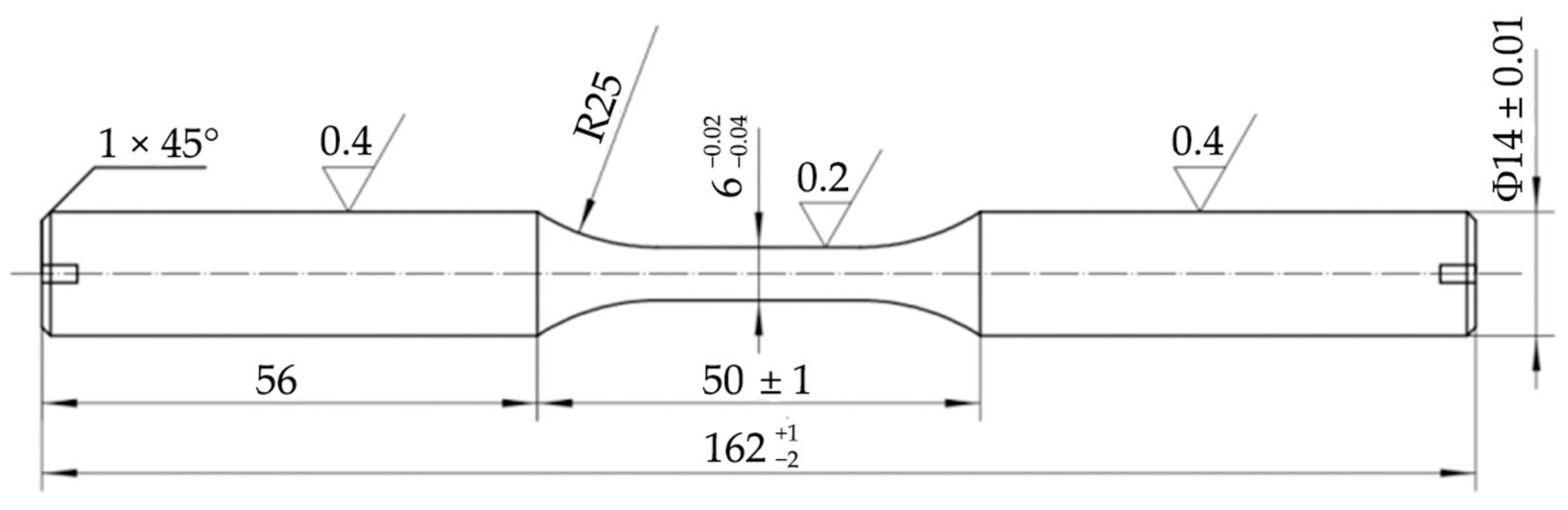
2.2. Fatigue Test Method

The high-cycle fatigue behaviors (S-N data and crack initiation) of the steels were investigated via the rotating–bending fatigue test. The tests followed the standard GB/T 4337-2008. After rough machining, the specimens were subjected to different heat treatments, respectively, followed by precision polishing before the fatigue test. Fatigue tests were conducted up to 107 cycles at different stress amplitudes at a stress ratio R = −1 using the rotating bar two-point bending fatigue testing machine (PQ1-6 type, Jinan Testing Equipment IE Co., Ltd., Shandong, China). The stress cycling rate was 5000 rpm, and the tests were carried out at ambient atmosphere. The fatigue strength was measured by the staircase method (i.e., the up and down method) with at least six pairs in order to increase the confidence of results. The geometry and dimensions of the smooth round bar specimens for the two-point bending fatigue testing are shown in Figure 2. The fracture surface of the failure specimens were observed by SEM. The characteristic dimensions for the crack initiation regions (i.e., size of inclusion, FGA and fish-eye) were measured from the SEM images.

3. Results and Discussion
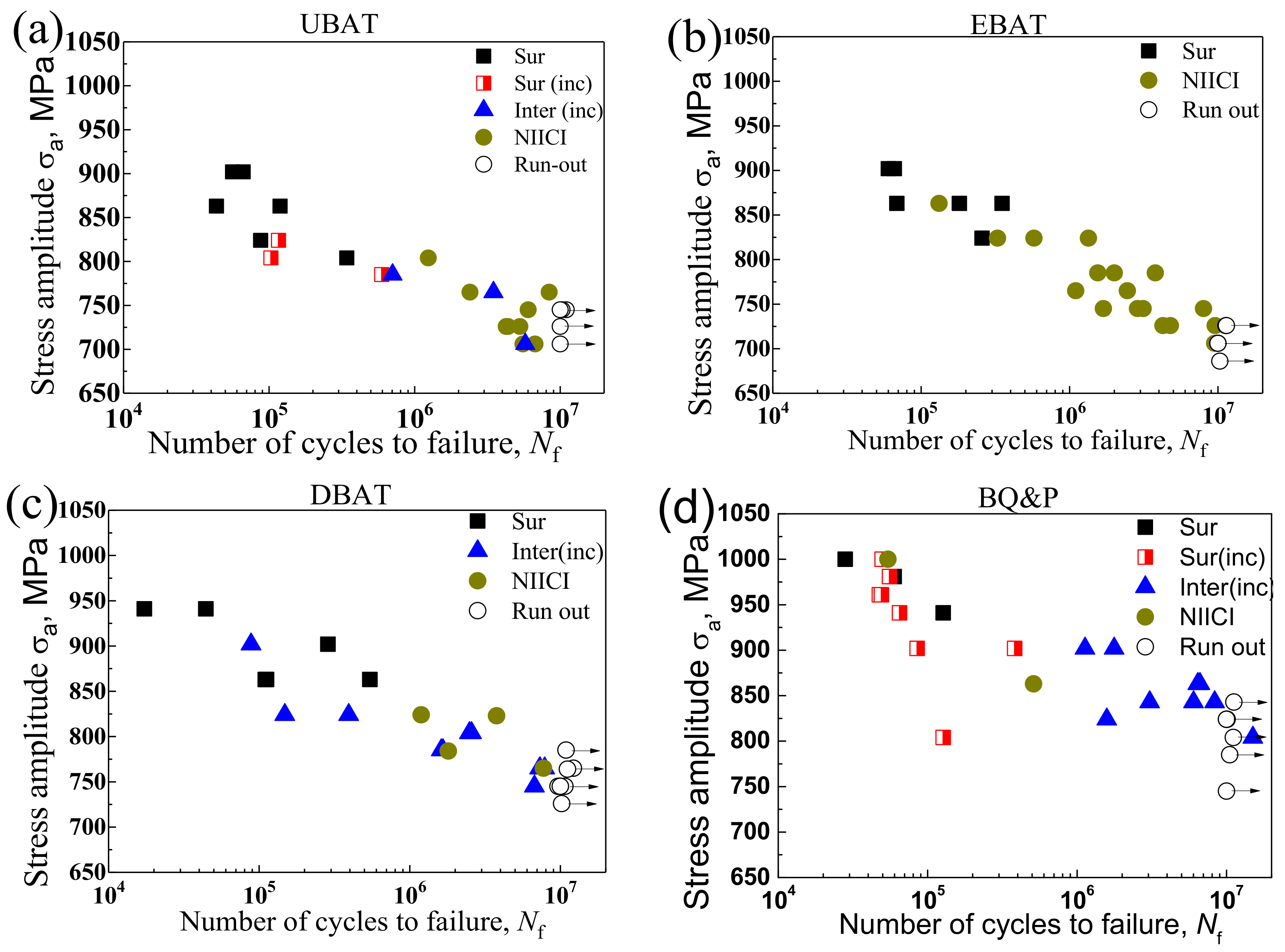
3.1. S-N Diagram

Figure 3 shows the S-N data consisting of the stress amplitude, σa, vs. fatigue life, Nf, of the four bainitic steels within the high-cycle fatigue regime from 104 to 107 cycles. The mean fatigue strength at 107 cycles of the UBAT, EBAT, DBAT and BQ&P samples are listed in Table 2, which is determined by the conventional staircase method. The ratios of the apparent mean fatigue limit to the tensile strength (σ−1/Rm) of the four variants can also be found in Table 2. The improved fatigue strength might be attributed to the elimination of the blocky M/A islands and the refined microstructure.
The symbols and abbreviations in Figure 3 indicate various fatigue crack initiation sites. Based on the fracture surface observation, it is observed that the specimens fail from the surface at a relatively higher stress amplitude for the four bainitic steels, which is related to the surface defect or the formation of extrusions and intrusions in the surface grains. When the stress amplitude decreases and Nf exceeds 106, the crack initiation site tends to transit from the specimen surface to the interior under a relatively low cyclic stress. It is noted that the interior crack initiation sites are either interior inclusions or microstructures, resulting in two interior crack initiation modes, namely the IICI and NIICI.
The ratios of the fatigue crack initiation sites are different in the four bainitic steels which failed within 106–107 cycles. Due to reduced inclusion size by the electroslag remelting process, all the EBAT samples crack from the interior microstructure (i.e., NIICI) within 106–107 cycles. For the UBAT samples, the cracks initiate from both the interior inclusions and the subsurface microstructure, e.g., there are eight specimens out of ten cracked by the NIICI mode. It is noted that the EBAT and UBAT steels have a similar fatigue strength despite the different ratios of the crack initiation sites. Hence, the microstructure has a dominant effect on the fatigue properties of the BAT steels. For the DBAT samples, the cracks also initiate from both the interior inclusions and the microstructure when the Nf exceeds 106, but the ratio of the NIICI mode in the DBAT is less than the UBAT samples. There are only four NIICI specimens out of twelve in the DBAT specimens. In addition, only interior-inclusion-induced fractures are observed for the BQ&P specimens within 106–107 cycles. There are two specimens cracked with the NIICI mode in the BQ&P specimens within 105–106 cycles. It is inferred that the fatigue limits of the samples treated by the DBAT and BQ&P heat treatments are determined by the competitive effect of the microstructure and inclusions. The fatigue cracks initiate from either the microstructure or the inclusion, depending on which of the two is more damaging.

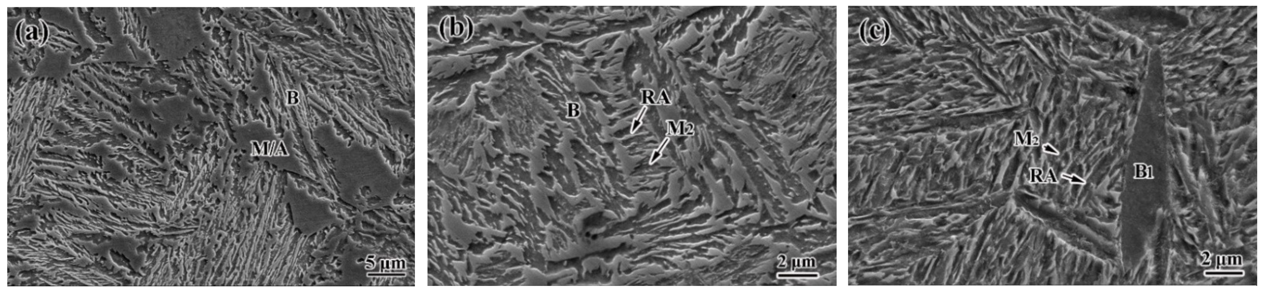
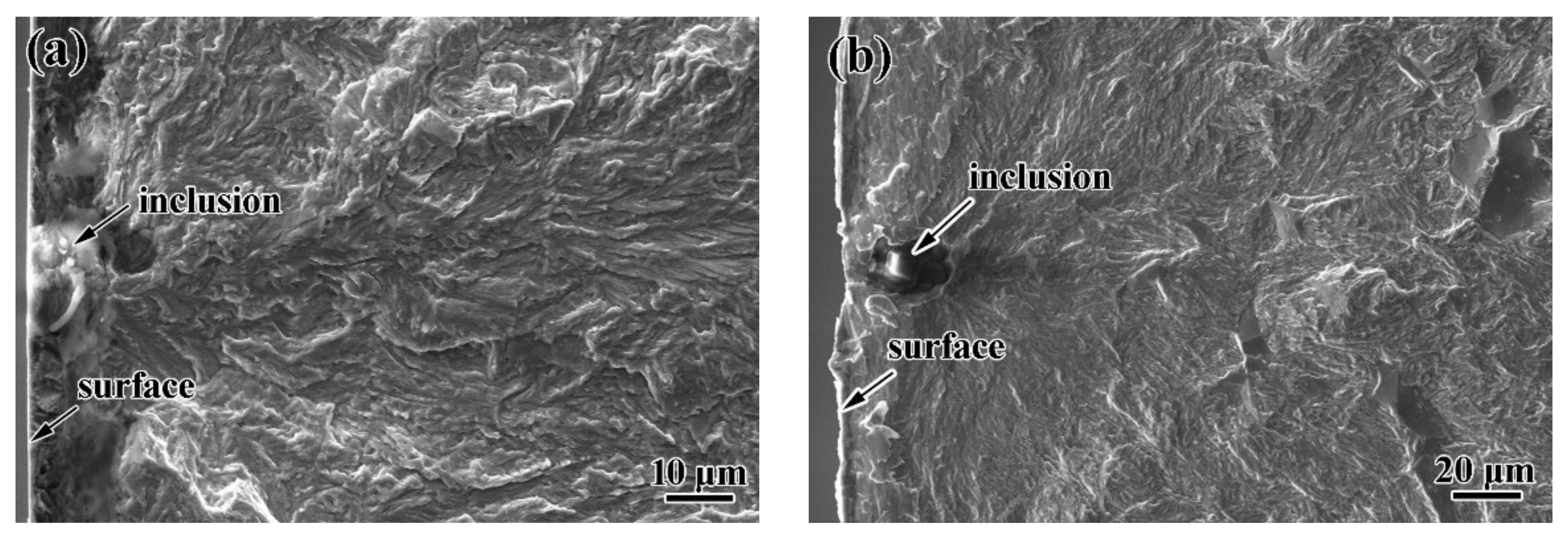
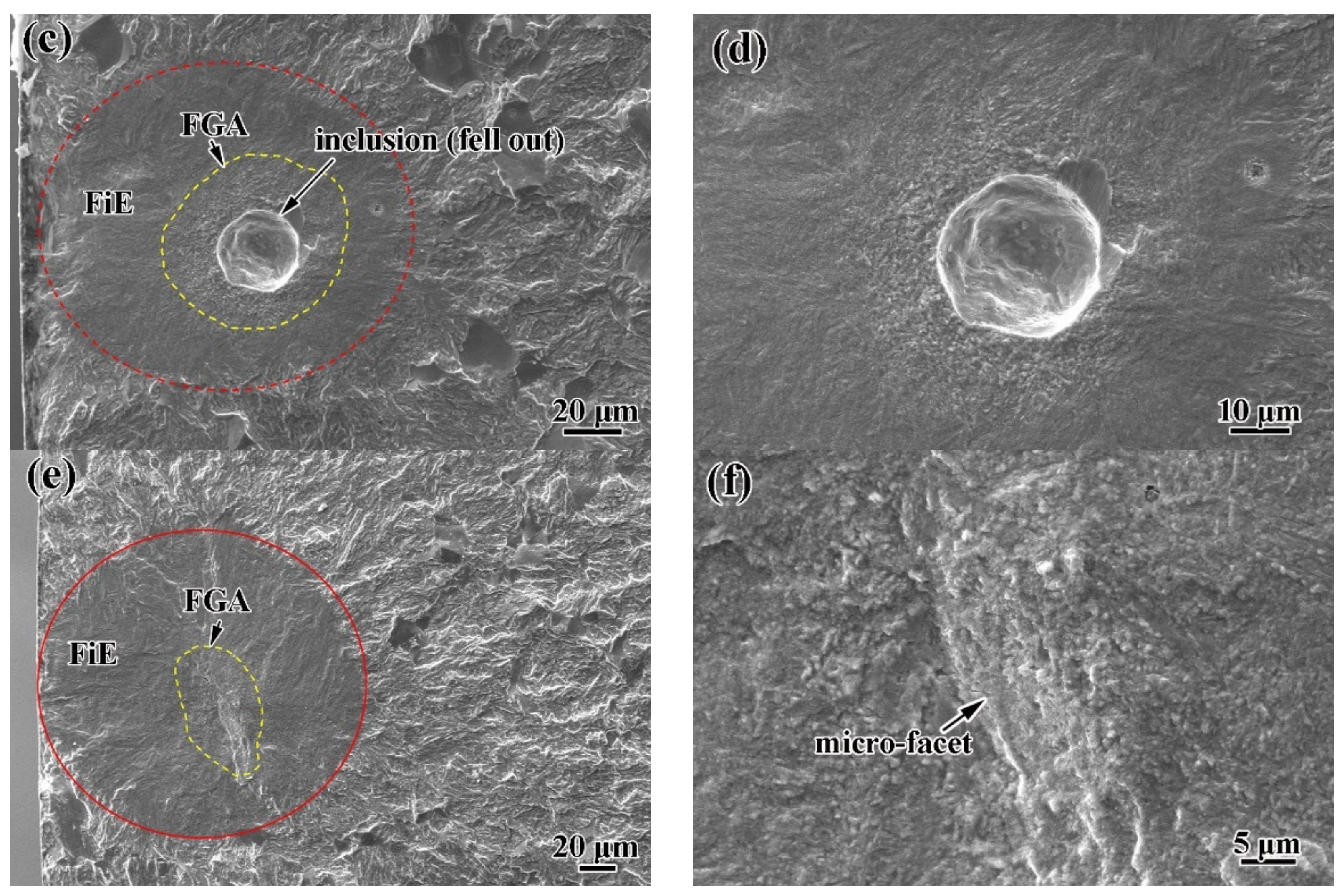
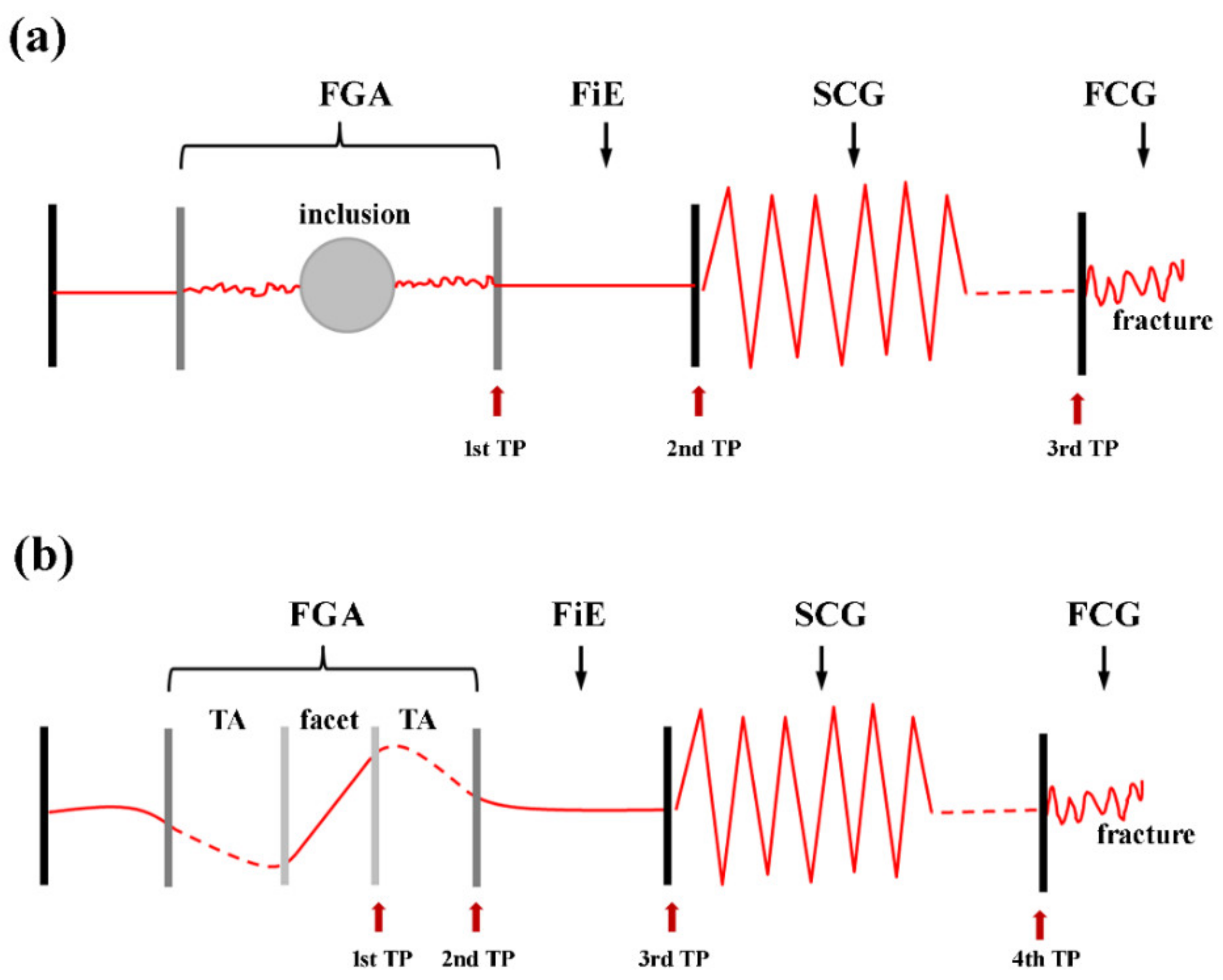
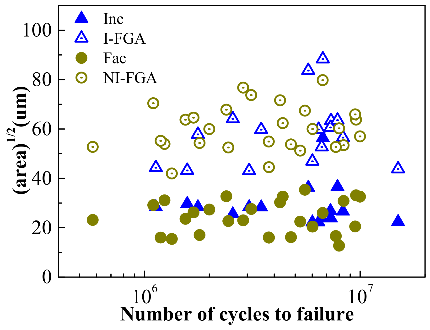
3.2. Fracture Surface Observation

Figure 4 shows the SEM images of typical fracture surfaces of the four bainitic steels. At the relatively high stress amplitude, the cracks tend to initiate from the surface defect or the surface inclusions (Figure 4a,b). The depth of the inclusion from the surface is comparable to its size. In this case of the surface-inclusion-induced crack initiation, the fish-eye morphology is not formed. As indicated in Figure 3, the crack initiation site tends to transit from the specimen surface to the interior under a relatively low cyclic stress. For the subsurface of the interior-inclusion-induced crack initiation (IICI), we can find a typical fish-eye morphology, which is characterized by a ring-like fish-eye surrounding the FGA area in the vicinity of the inclusion (Figure 4c,d). The fracture surface of the “noninclusion-induced crack initiation” (NIICI) is shown in Figure 4e,f. Similar to the IICI fracture surface, the fish-eye with the noninclusion-induced FGA area is also formed in the NIICI fracture surface. The detailed SEM observation of the FGA (Figure 4f) shows that there is a micron-sized facet surrounding the undulation area within the FGA. Our previous work [27] on the NIICI fracture mechanism showed that the microfacet is close to the plane of maximum shear stress, and essentially resulted from the fracture surface of stage I small crack, while the surrounding undulation area corresponded to the transition area (TA) from the stage I crack to the stage II crack. The microstructural features affect the geometrical morphology of the transition area (TA) and also determine the periphery of the FGA area. Based on the 3D observation in previous study, the comparison between the IICI and NIICI fractures is shown by the schematics of the fatigue failure process from crack initiation to the final fracture (Figure 5) [29,30].
In the geometric parameter models proposed by Murakami et al. [15], the size of crack initiation site (i.e., inclusion or defect) is denoted by the term “√area”, which is the projected area of the inclusion or the defect on to the plane perpendicular to the direction of the maximum tensile stress. The detailed method of measuring the project area can be seen in Ref. [31]. The characteristic dimensions of the √area measured from the SEM observations for the interior IICI and NIICI modes of the four bainitic steels are shown in Figure 6. We used 2 a Inc = a r e a Inc , 2 a GBF = a r e a GBF and 2 a fisheye = a r e a fisheye . It is noted that the sizes of the inclusions and microfacets are mainly within a relatively small range between 15 and 40 μm, and the FGA sizes of the IICI and NIICI modes are both distributed in the range between 40 and 85 μm.

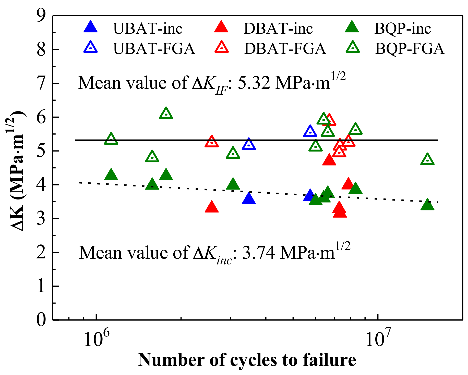
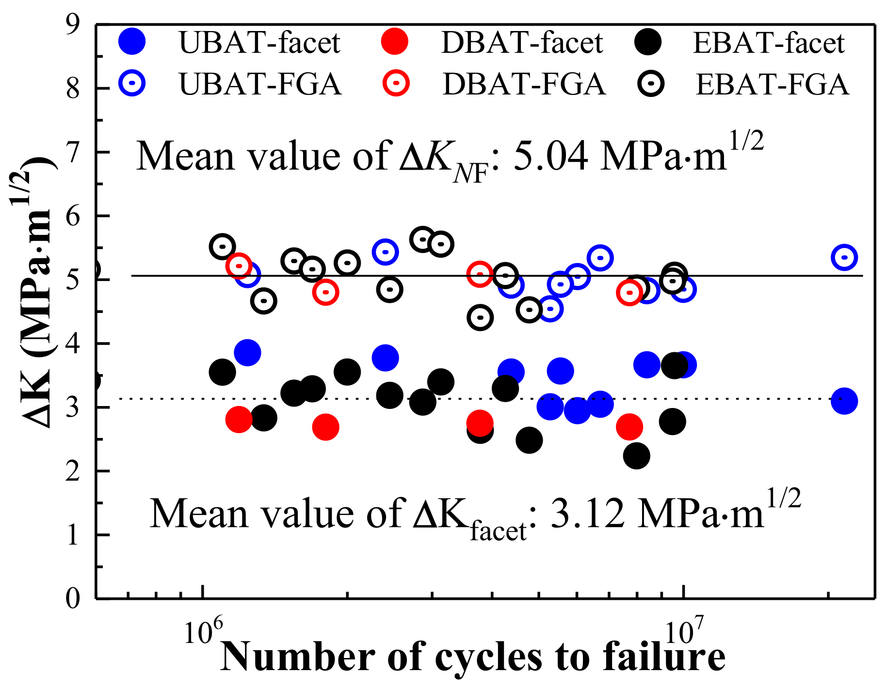
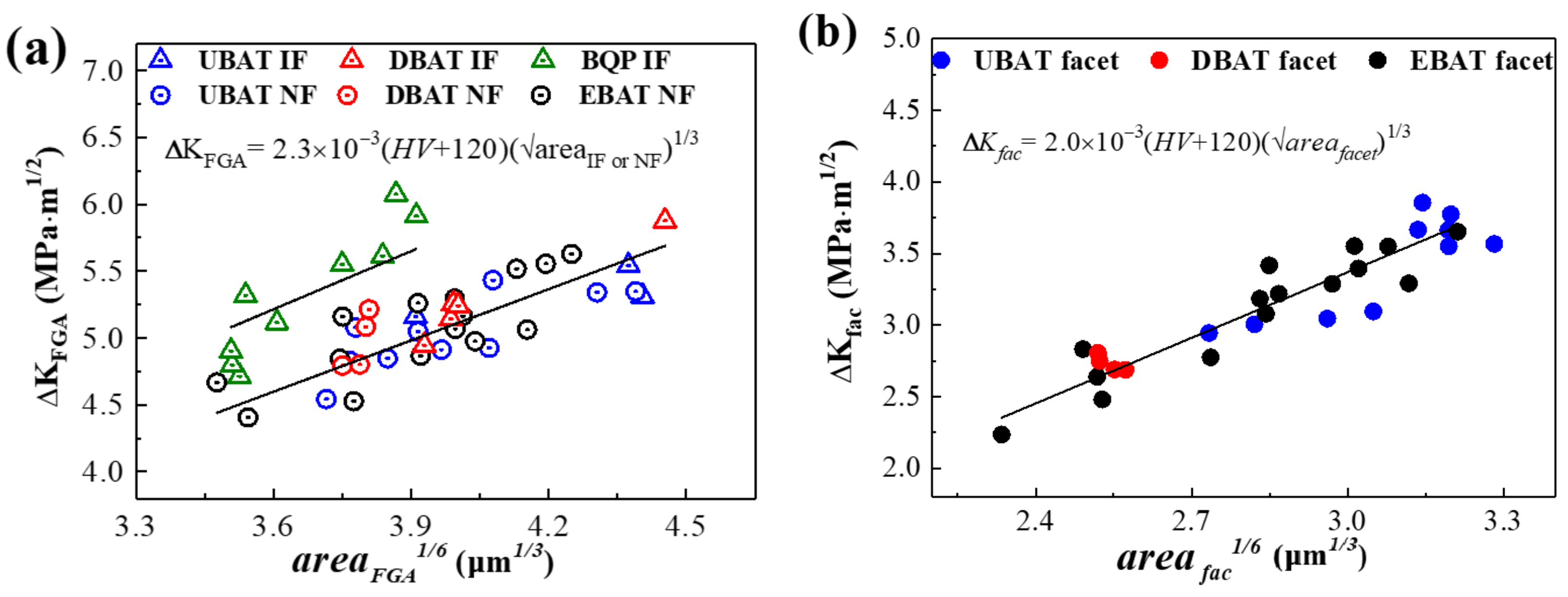
3.3. Stress Intensity Factor Analysis

The values of the stress intensity factor (SIF) range at the periphery of the inclusion (ΔKInc), microfacet (ΔKFac), the FGA around the inclusion (ΔKIF) and the FGA without the inclusion (ΔKNF) are calculated by using the following equation:
Δ K = 0.5 σ a   1 d / R π a r e a
where σa is the stress amplitude, d is the depth of the crack initiation site from the surface of the failed specimen, R is the radius of the specimen, area is the projected area on the plane perpendicular to tensile stress and a r e a is the equivalent diameter, respectively. For the surface inclusion or defect, the coefficient of 0.5 is replaced by 0.65 in the calculation.
The calculated values of ΔKinc, ΔKIF, ΔKfac and ΔKNF versus the fatigue life (Nf) are shown in Figure 7 and Figure 8, respectively. It is noted that the values of ΔKinc show a slightly decreasing trend with the increasing of Nf, while ΔKfac is almost constant at an average of 3.12 MPa·m1/2. The average values of ΔKinc and ΔKIF are ~3.74 MPa·m1/2 and 5.32 MPa·m1/2, respectively, which are slightly higher than ΔKfac and ΔKNF (~3.12 MPa·m1/2 and 5.04 MPa·m1/2, respectively).
Muakami and Endo [31,32] found that the ΔKth of a small defect is proportional to the √area1/3 and increases with the HV. They proposed two parameters, which are the geometric parameter √area and material parameter HV model, for the ΔKth of small defects, given in Equation (2):
Δ K t h = C 1 H V + C 2 a r e a 1 / 3
where C1 and C2 are material independent constants, √area denotes the crack size, the unit of ΔKth is MPa·m1/2, the unit of √area is μm and the unit of HV is kgf/mm−2. For a wide range of materials, the value of C2 is evaluated to be 120 [32].
Figure 9 shows the relationship between ΔK and √area 1/3 of the bainitic steels. It is shown that ΔKFGA and √areaIF or NF 1/3 (Figure 9a) in this work coincide with Equation (2), and the fitted value of C1 is 2.3 × 10⁻³. It is noted that the cube root of the microfacet size (√area fac 1/3) keeps a linear relation with ΔKfac and also agrees with the Equation (2). Figure 9b shows the relation and the fitted value of C1 is about 2.0 × 10⁻³.

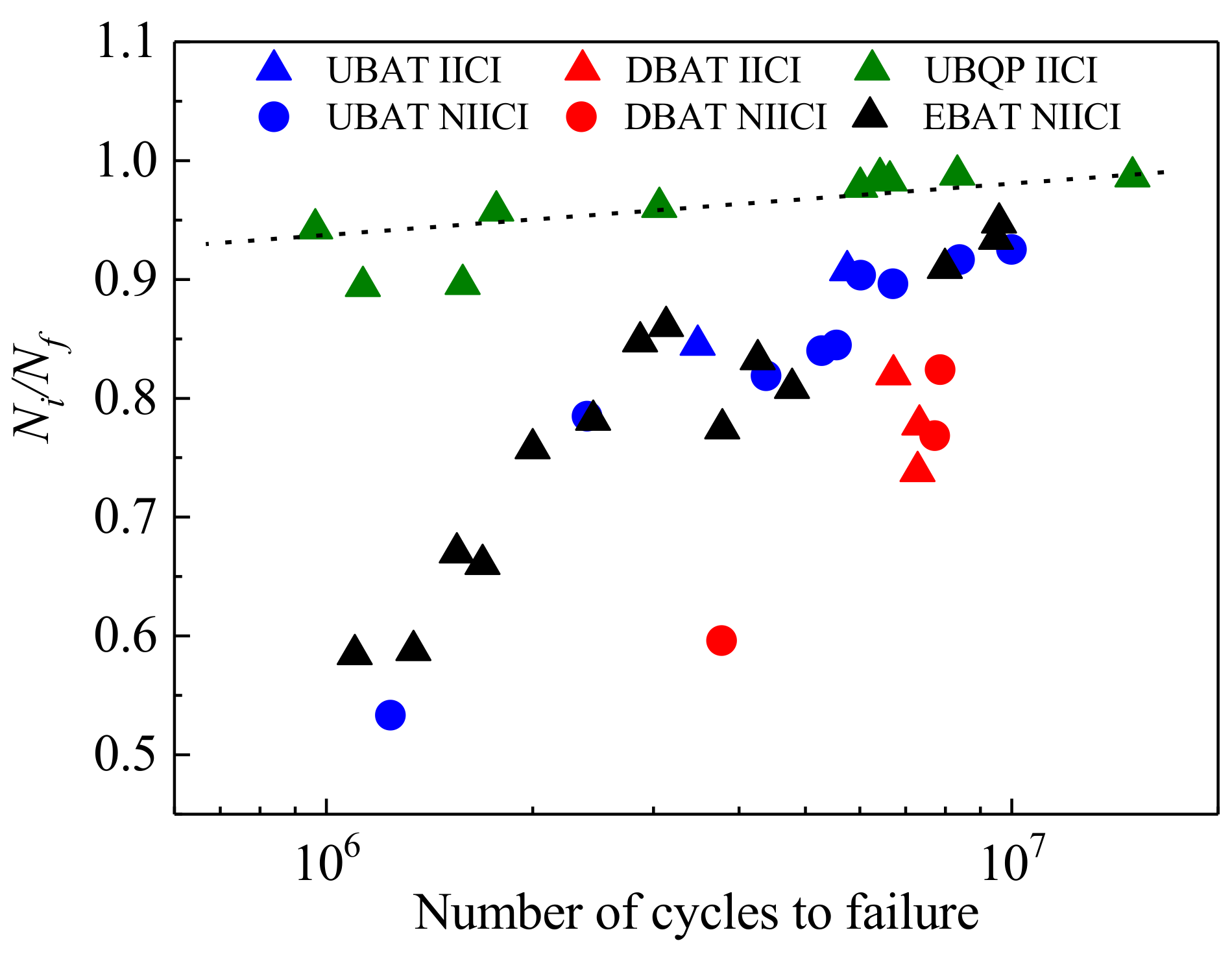
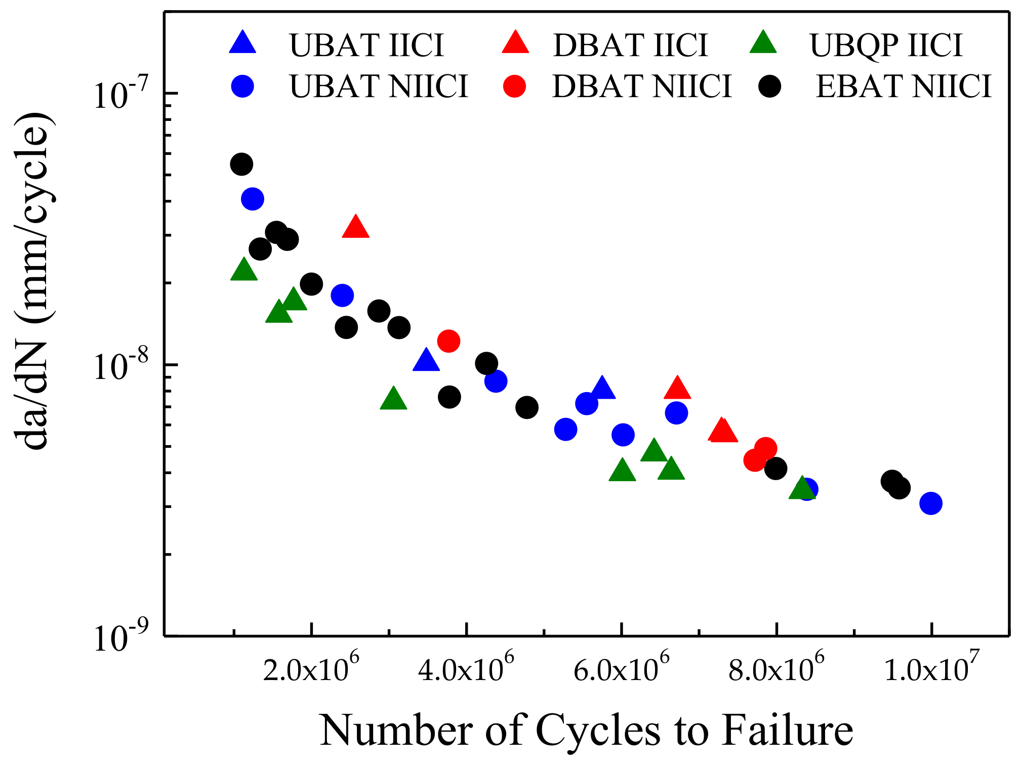
3.4. Estimation of Crack Initiation Life

As indicated in Figure 5, for the interior failure, the total fatigue life can be divided into four stages: (i) the crack initiation life, i.e., the fatigue life consumed within the FGA, (ii) the stable crack growth life outside the FGA but within the fish-eye, (iii) the steady crack growth life outside the fish-eye and (iv) the fast crack growth life. It is reported that the Paris relation can be used to describe the stable crack growth process when the SIF exceeds ΔKth [33]. As indicated in Figure 7 and Figure 8, the SIF at the periphery of the FGA is close to the ΔKth of high-strength steels (4–5 MPa·m1/2). Hence, the Paris equation can be used to calculate the fatigue life from the boundary of the FGA to that of the fish-eye (N1) and the fatigue life from the fish-eye to the critical boundary given by the fracture toughness of the material (Np). N1 and Np are calculated by using the following equations [12]:
d a / d N = c Δ K m
N 1 = 2 m 2 · c · Y m · σ m · 1 area GBF / 2 m 2 / 2 1 area FIE / 2 m 2 / 2
N p = 2 m 2 · c · Y m · σ m · 1 area FIE m 2 / 2 1 a SCG m 2 / 2
N i = N f N 1 N p
where c and m are the parameters in relation with the given material and which can be obtained by the Paris equation. Although the propagation of long cracks is not as sensitive to the microstructure as small cracks, the microstructure also affects the propagation behavior of cracks in the Paris regime via the deflection effect from the microstructural boundaries [34]. Hence, the parameter of c and m will be related to the microstructure and heat treatment. Based on fatigue crack growth testing, approximately, the values of c and m are 6.45 × 10⁻¹⁴ and 4.95 for the UBAT and EBAT steels, 3.34 × 10⁻¹⁴ and 4.68 for the DBAT steels and 4.17 × 10⁻¹⁴ and 5.87 for the BQ&P steels. It should be noted that the fatigue crack propagation resistance could also be affected by local residual stress in the bainite/martensite steels [35]. Meanwhile, the residual stress can be eliminated via heat treatment, such as an isothermal holding during the martensite transformation temperature range, as described in Ref. [35]. In the present work, the three heat treatments, such as BAT, DBAT and BQ&P, include an isothermal holding, which could reduce the adverse effect of the residual stress. Y is the related shape factor and is taken as 0.5 π , while σ is the stress amplitude, the values of areaFGA, areaFIE and aSCG (size of crack stable propagation area) can be obtained by the SEM observations and Ni is the fatigue life consumed within the FGA. The fatigue life of the rapid crack propagation is ignored due to its few numbers of cycles.
The relationships between Ni/Nf and Nf for the bainitic steels are shown in Figure 10. It is clear that the values of Ni/Nf of the four steels exhibit an increasing tendency with the increasing of the total fatigue life, independent with the crack initiation sites. For the BQ&P specimens, which mainly cracked from the interior inclusions, the crack initiation life (Ni) contributed by the formation of the FGA is more than 90%. For the other three steels, the value of Ni/Nf is scattered, but is over 50%. This means that majority of fatigue life is consumed within the FGA for both IICI and NIICI modes.
Figure 11 shows the evaluated crack growth rates (da/dN) within the FGA, calculated from the FGA size and the fatigue life consumed by this region. It can find that the average crack growth rate (da/dN) within the FGA decreases with the increasing of the total fatigue life, independent of the crack initiation sites. Meanwhile, the values of da/dN for the four bainitic steels are in the range between 10−7 and 10−9 mm/cycle, which is lower than one lattice spacing of α-Fe and γ-Fe (~10−7 mm).

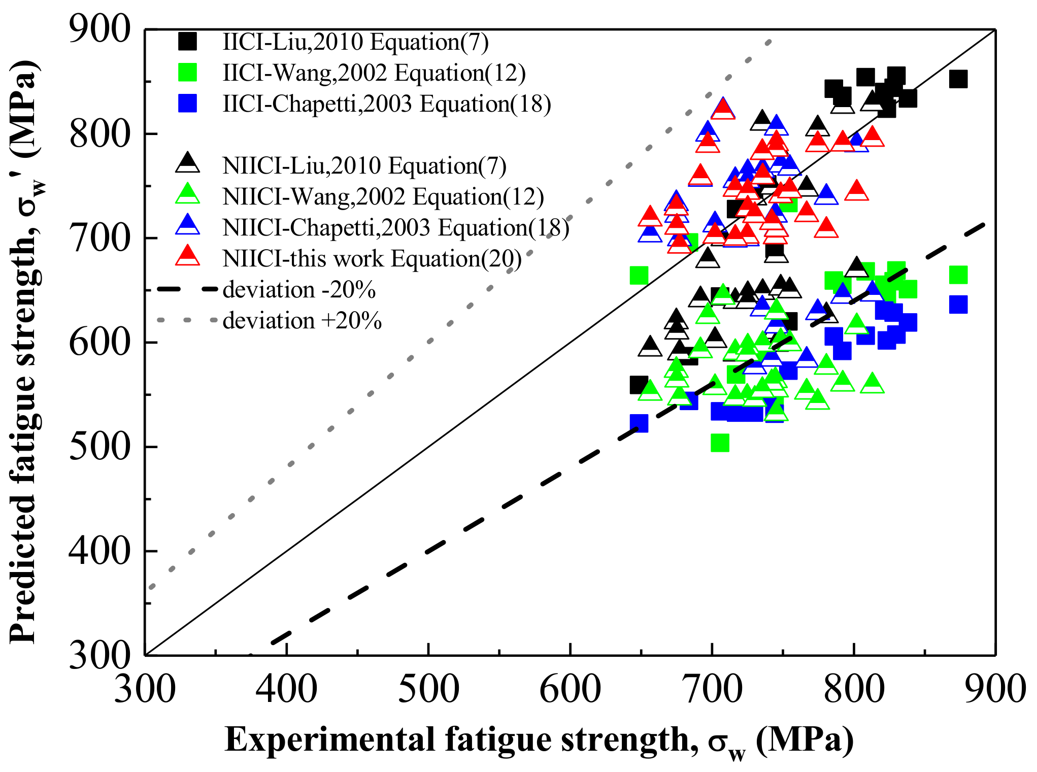
3.5. Evaluation of Interior Fatigue Strength

For the high-cycle fatigue, there are several well-known existing formulas governed via the parameter of √area to predict the fatigue strength. The Basquin equation is usually used to describe the S-N relationship within the high-cycle fatigue (HCF) regime for a stress ratio R = 1, as shown in Equation (7):
σ a = σ f ·   2 N b
where σa is the cyclic stress amplitude in MPa, N is the number of cycles to failure, σ f is the fatigue strength coefficient and b is the fatigue strength exponent.
Liu et al. [36] modified the parameters of Equation (7) and proposed an expression based on the understanding of the effect of hydrogen during formation of GBF (namely, the hydrogen embrittlement mechanism, as proposed by Murakmi et al. [32]) to predict the fatigue strength ( σ W V H ) of high-strength steels in the VHCF regime. It is supposed that the σa equals to σ W H at Nf = 106 cycles and σa equals to σ W V H at Nf = 109 cycles, respectively. The σ W H indicates fatigue strength in the HCF regime. The σ f and b in the Basquin exponent can be estimated using a different set of formulae. Thus, they proposed a fatigue strength coefficient and a Basquin exponent given in Equations (10) and (11), based on the Basquin equation:
σ W H = 2 H v + 120 a r e a i n 1 6
σ W V H = 2.7 H v + 120 15 16 a r e a i n 3 16
σ f = 1.12 H v + 120 9 8 a r e a i n 1 8
b = 1 3 log 1.35 H v + 120 1 16 a r e a i n 1 48
where σ W H and σ W V H are the fatigue strength amplitudes in MPa, HV is the Vickers hardness in kgf/mm2 and √areain (in μm) is the effective size of the failure origin (defect, inclusion and crack) that causes the failure.
Wang et al. [13,37] introduced fatigue life (N) into the Murakami model, and modified the model for fatigue strength predications, where the failure is caused by internal inclusions (or defects), as given in Equation (12):
σ W = 3.09 0.120 log N ·   H v + 120 a r e a i n 1 6 1 R 2 α
Chapetti et al. [38] proposed a relation, which is given in Equation (13), between the ODA (also called FGA) size and the number of cycles to failure:
  R O D A R i n = 0.25 N f 0.125
where R O D A and R i n are the ODA and inclusion sizes, respectively. The crack length a, the ODA size R O D A and the inclusion R i n can be evaluated by combining the following Equation (14):
a r e a = π a
a r e a O D A = π R O D A
a r e a i n c l u s i o n = π R i n
The pure fatigue crack propagation Δ K t h can be calculated using the a r e a parameter model. Murakami et al. [31,32] proposed Equation (15) to evaluate the threshold value. Thus, Δ K t h   (Equation (16)) can be obtained using Equations (14) and (15):
Δ K t h = 3.3 × 10 3 H V + 120 a r e a O D A 1 3
Δ K t h = 4 × 10 3 H V + 120 a 1 3
The applied Δ K for a penny-shaped internal crack can be evaluated by Equation (17):
Δ K = 2 π Δ σ π a
With Equations (13), (14), (16) and (17), Chapetti et al. provided a fatigue strength prediction formula under the R = −1 loading condition, rearranging to Basquin’s model, given in Equation (18):
σ W = 2.5 ·   H V + 120 a r e a i n 1 6   2 N 1 48
with σ W in MPa,√areain in μm and HV in kgf/mm2.
As indicated in Figure 9, the size of the microfacets have a linear relation with Δ K f a c , and the relation is given in Equation (19):
Δ K f a c = 2.0 × 10 3 H V + 120 a r e a 1 / 3
Hence, combining Equations (1) and (20) with Δ K f a c =   K I   m a x , and rearranging to the Basquin equation, the fatigue strength of the specimens which cracked from the microfacets can be expressed as:
σ W = 4 π ·   H v + 120 a r e a f a c 1 6
Figure 12 shows the fatigue strength predicted by Equations (7), (10)–(12), (18) and (20) compared with experimental fatigue strength. Dot and dash lines represent the values of the deviating fatigue strengths of +20% and −20%, respectively. It is shown that, with Liu’s model, the predicted fatigue strength of the IICI specimens fits the experimental data very well, but for the NIICI specimens, it is scattered. Wang’s model is relatively conservative for the experimental results, while the predicted fatigue strength is deviated by −20% with the experimental results. The fatigue strength of the NIICI specimens predicted by Chapetti’s model is also scattered. Chapetti’s predication is also conservative for the IICI specimens.
In contrast, in the present work, the fatigue strengths which predicted by the sizes of microfacets fit the experimental data very well. This means that it is convenient to predict the fatigue strength of the NIICI specimens through the parameters of the HV of the specimens and the √areafac. It should be noted that the microfacet essentially resulted from the fracture surface of the stage I small crack, which is strongly related to the specially oriented slip plane in the microstructure [11,25]. Hence, the relationship between the microfacet and the fatigue strength built in this work would be helpful to correlate the fatigue strength to the microstructure of bainitic steels.

4. Conclusions

In this work, the medium-carbon bainitic steels with different microstructures and inclusion sizes were prepared by controlling the melting processes and the heat treatments (i.e., BAT, DBAT and BQ&P). Based on the S-N data and the fracture surface observations, we predicted the fatigue strength and the fatigue life of both the NIICI (noninclusion-induced crack initiation) and the IICI (inclusion induced crack initiation)-fatigued specimens within the HCF regime. The main conclusions are described as follows:
  • The inclusion and microstructure affect together the fatigue limit and fatigue crack initiation sites of the bainitic steels. The high-cycle fatigue properties of the DBAT and BQ&P steels are enhanced compared to the conventional BAT steels because of the refined microstructure and the elimination of blocky martensite/austenite islands.
  • The cube root of the microfacet size (√area fac 1/3) keeps a linear relation with the stress intensity factor (SIF) range of the microfacet ΔKfac, which follows Δ K f a c = 2.0 × 10 3 H V + 120 a r e a 1 / 3 .
  • The fatigue crack initiation life (Ni) consumed within the FGA is greater than 50% of the total fatigue life, independent of the crack initiation sites. The values of Ni/Nf exhibit an increasing tendency with the increasing of the total fatigue life for both the IICI and NIICI specimens.
  • The fatigue strength of the NIICI specimens can be predicted through the two parameters of the hardness of the specimens and the size of the microfacet (√areafac).

Author Contributions

Conceptualization, X.G. and G.G.; methodology, X.G. and Y.F.; validation, Y.F. and M.L.; data curation, M.L. and Y.F.; writing—original draft preparation, Y.F. and X.G.; writing—review and editing, X.G., C.F. and G.G.; funding acquisition, G.G., C.F. and X.W. All authors have read and agreed to the published version of the manuscript.

Funding

This research was funded by the Fundamental Research Funds for the Central Universities: no. 2021YQ001; the Joint Funds of National Natural Science Foundation of China: no. U1834202; the National Key Technologies Research and Development Program of China: no. 2021YFB3703500.

Institutional Review Board Statement

Not applicable.

Informed Consent Statement

Not applicable.

Data Availability Statement

Data will be made available upon request.

Conflicts of Interest

The authors declare no conflict of interest.

References

  1. Bouaziz, O.; Zurob, H.; Huang, M. Driving force and logic of development of advanced high strength steels for automotive applications. Steel Res. Int. 2013, 84, 937–947. [Google Scholar] [CrossRef]
  2. Dai, Z.; Chen, H.; Ding, R.; Lu, Q.; Zhang, C.; Yang, Z.; van der Zwaag, S. Fundamentals and application of solid-state phase transformations for advanced high strength steels containing metastable retained austenite. Mater. Sci. Eng. R Rep. 2021, 143, 100590. [Google Scholar] [CrossRef]
  3. Long, X.; Kang, J.; Lv, B.; Zhang, F. Carbide-free bainite in medium carbon steel. Mater. Des. 2014, 64, 237–245. [Google Scholar] [CrossRef]
  4. Luo, P.; Gao, G.; Zhang, H.; Tan, Z.; Misra, R.D.; Bai, B. On structure-property relationship in nanostructured bainitic steel subjected to the quenching and partitioning process. Mater. Sci. Eng. A 2016, 661, 1–8. [Google Scholar] [CrossRef] [Green Version]
  5. Wang, X.; Liu, C.; Qin, Y.; Li, Y.; Yang, Z.; Long, X.; Wang, M.; Zhang, F. Effect of tempering temperature on microstructure and mechanical properties of nanostructured bainitic steel. Mater. Sci. Eng. A 2022, 832, 142357. [Google Scholar] [CrossRef]
  6. Gao, G.; Zhang, H.; Gui, X.; Luo, P.; Tan, Z.; Bai, B. Enhanced ductility and toughness in an ultrahigh-strength Mn–Si–Cr–C steel: The great potential of ultrafine filmy retained austenite. Acta Mater. 2014, 76, 425–433. [Google Scholar] [CrossRef]
  7. Zhang, M.R.; Gu, H.C. Microstructure and properties of carbide free bainite railway wheels produced by programmed quenching. Mater. Sci. Technol. 2007, 23, 970–974. [Google Scholar] [CrossRef]
  8. Sakai, T.; Sato, Y.; Oguma, N. Characteristic S-N properties of high-carbon-chromium-bearing steel under axial loading in long-life fatigue. Fatigue Fract. Eng. Mater. Struct. 2002, 25, 765–773. [Google Scholar] [CrossRef]
  9. Ogawa, T.; Stanzl-Tschegg, S.E.; Schönbauer, B.M. A fracture mechanics approach to interior fatigue crack growth in the very high cycle regime. Eng. Fract. Mech. 2014, 115, 241–254. [Google Scholar] [CrossRef]
  10. Shiozawa, K.; Morii, Y.; Nishino, S.; Lu, L. Subsurface crack initiation and propagation mechanism in high-strength steel in a very high cycle fatigue regime. Int. J. Fatigue 2006, 28, 1521–1532. [Google Scholar] [CrossRef]
  11. Gao, G.; Liu, R.; Fan, Y.; Qian, G.; Gui, X.; Misra, R.D.K.; Bai, B. Mechanism of subsurface microstructural fatigue crack initiation during high and very-high cycle fatigue of advanced bainitic steels. J. Mater. Sci. Technol. 2022, 108, 142–157. [Google Scholar] [CrossRef]
  12. Hong, Y.; Lei, Z.; Sun, C.; Zhao, A. Propensities of crack interior initiation and early growth for very-high-cycle fatigue of high strength steels. Int. J. Fatigue 2014, 58, 144–151. [Google Scholar] [CrossRef] [Green Version]
  13. Wang, Q.Y.; Bathias, C.; Kawagoishi, N.; Chen, Q. Effect of inclusion on subsurface crack initiation and gigacycle fatigue strength. Int. J. Fatigue 2002, 24, 1269–1274. [Google Scholar] [CrossRef]
  14. Tanaka, K.; Akiniwa, Y. Fatigue crack propagation behaviour derived from S-N data in very high cycle regime. Fatigue Fract. Eng. Mater. Struct. 2002, 25, 775–784. [Google Scholar] [CrossRef]
  15. Murakami, Y.; Yokoyama, N.N.; Nagata, J. Mechanism of fatigue failure in ultralong life regime. Fatigue Fract. Eng. Mater. Struct. 2002, 25, 735–746. [Google Scholar] [CrossRef]
  16. Romano, S.; Brückner-Foit, A.; Brandão, A.; Gumpinger, J.; Ghidini, T.; Beretta, S. Fatigue properties of AlSi10Mg obtained by additive manufacturing: Defect-based modelling and prediction of fatigue strength. Eng. Fract. Mech. 2018, 187, 165–189. [Google Scholar] [CrossRef]
  17. Sun, C.; Xie, J.; Zhao, A.; Lei, Z.; Hong, Y. A cumulative damage model for fatigue life estimation of high-strength steels in high-cycle and very-high-cycle fatigue regimes. Fatigue Fract. Eng. Mater. Struct. 2012, 35, 638–647. [Google Scholar] [CrossRef] [Green Version]
  18. Zhu, M.L.; Jin, L.; Xuan, F.Z. Fatigue life and mechanistic modeling of interior micro-defect induced cracking in high cycle and very high cycle regimes. Acta Mater. 2018, 157, 259–275. [Google Scholar] [CrossRef]
  19. Nehila, A.; Li, W.; Gao, N.; Xing, X.; Zhao, H.; Wang, P.; Sakai, T. Very high cycle fatigue of surface carburized CrNi steel at variable stress ratio: Failure analysis and life prediction. Int. J. Fatigue 2018, 111, 112–123. [Google Scholar] [CrossRef]
  20. Jha, S.K.; Larsen, J.M.; Rosenberger, A.H. Towards a physics-based description of fatigue variability behavior in probabilistic life-prediction. Eng. Fract. Mech. 2009, 76, 681–694. [Google Scholar] [CrossRef]
  21. Yang, M.; Gao, C.; Pang, J.; Li, S.; Hu, D.; Li, X.; Zhang, Z. High-Cycle Fatigue Behavior and Fatigue Strength Prediction of Differently Heat-Treated 35CrMo Steels. Metals 2022, 12, 688. [Google Scholar] [CrossRef]
  22. Chai, G.C. The formation of subsurface non-defect fatigue crack origins. Int. J. Fatigue 2006, 28, 1533–1539. [Google Scholar] [CrossRef]
  23. Zhao, P.; Gao, G.; Misra, R.D.K.; Bai, B. Effect of microstructure on the very high cycle fatigue behavior of a bainite/martensite multiphase steel. Mater. Sci. Eng. A 2015, 630, 1–7. [Google Scholar] [CrossRef]
  24. Li, W.; Li, M.; Sun, R.; Xing, X.; Wang, P.; Sakai, T. Faceted crack induced failure behavior and micro-crack growth based strength evaluation of titanium alloys under very high cycle fatigue. Int. J. Fatigue 2020, 131, 105369. [Google Scholar] [CrossRef]
  25. Zhou, Y.; Sun, J.; Pan, X.; Qian, G.; Hong, Y. Microstructure evolution and very-high-cycle fatigue crack initiation behavior of a structural steel with two loading intermittence modes. Int. J. Fatigue 2022, 161, 106904. [Google Scholar] [CrossRef]
  26. Gao, G.; Liu, R.; Wang, K.; Gui, X.; Misra, R.D.K.; Bai, B. Role of retained austenite with different morphologies on sub-surface fatigue crack initiation in advanced bainitic steels. Scr. Mater. 2020, 184, 12–18. [Google Scholar] [CrossRef]
  27. Gao, G.; Xu, Q.; Guo, H.; Gui, X.; Zhang, B.; Bai, B. Effect of inclusion and microstructure on the very high cycle fatigue behaviors of high strength bainite/martensite multiphase steels. Mater. Sci. Eng. A 2019, 739, 404–414. [Google Scholar] [CrossRef]
  28. Gao, G.; Bai, B.; Zhang, H.; Gui, X.; Tan, Z.; Weng, Y. Enhanced TRIP effect in a lean alloy steel treated by a ‘disturbed’ bainitic austempering process. Heat Treat. Surf. Eng. 2019, 1, 72–77. [Google Scholar] [CrossRef]
  29. Gao, G.; Wang, K.; Su, H.; Gui, X.; Li, Z.; Misra, R.D.K.; Bai, B. The potential of mechanical twinning in ultrafine retained austenite to enhance high cycle fatigue property of advanced bainitic steels. Int. J. Fatigue 2020, 139, 105804. [Google Scholar] [CrossRef]
  30. Gui, X.; Gao, G.; An, B.; Misra, R.D.K.; Bai, B. Relationship between non-inclusion induced crack initiation and microstructure on fatigue behavior of bainite/martensite steel in high cycle fatigue/very high cycle (HCF/VHCF) regime. Mater. Sci. Eng. A 2021, 803, 140692. [Google Scholar] [CrossRef]
  31. Murakami, Y.; Endo, M. Effects of defects, inclusions and inhomogeneities on fatigue strength. Int. J. Fatigue 1994, 16, 163–182. [Google Scholar] [CrossRef]
  32. Murakami, Y.; Nomoto, T.; Ueda, T. Factors influencing the mechanism of superlong fatigue failure in steels. Fatigue Fract. Eng. Mater. Struct. 1999, 22, 581–590. [Google Scholar] [CrossRef]
  33. Marines-Garcia, I.; Paris, P.C.; Tada, H.; Bathias, C. Fatigue crack growth from small to long cracks in VHCF with surface initiations. Int. J. Fatigue 2007, 29, 2072–2078. [Google Scholar] [CrossRef]
  34. Kumar, A.; Singh, A. Microstructural effects on the sub-critical fatigue crack growth in nano-bainite. Mater. Sci. Eng. A 2019, 743, 464–471. [Google Scholar] [CrossRef]
  35. Ostash, O.P.; Kulyk, V.V.; Poznyakov, V.D.; Haivorons’kyi, O.A.; Markashova, L.I.; Vira, V.V.; Duriagina, Z.A.; Tepla, T.L. Fatigue crack growth resistance of welded joints simulating the weld-repaired railway wheels metal. Arch. Mater. Sci. Eng. 2017, 86, 49–52. [Google Scholar] [CrossRef]
  36. Liu, Y.; Li, Y.; Li, S.; Yang, Z.; Chen, S.; Hui, W.; Weng, Y. Prediction of the SN curves of high-strength steels in the very high cycle fatigue regime. Int. J. Fatigue 2010, 32, 1351–1357. [Google Scholar] [CrossRef]
  37. Yang, K.; Huang, Q.; Wang, Q.; Chen, Q. Competing crack initiation behaviors of a laser additively manufactured nickel-based superalloy in high and very high cycle fatigue regimes. Int. J. Fatigue 2020, 136, 105580. [Google Scholar] [CrossRef]
  38. Chapetti, M.D.; Tagawa, T.; Miyata, T. Ultra-long cycle fatigue of high-strength carbon steels part II: Estimation of fatigue limit for failure from internal inclusions. Mater. Sci. Eng. A 2003, 356, 236–244. [Google Scholar] [CrossRef]
Figure 1. Microstructure of (a) BAT [28], (b) DABT and (c) BQ&P samples; B: bainite, Bl: leaf-shaped bainite, M/A: martensite/austenite, M2: carbon-depleted martensite, RA: retained austenite.
Metals 12 00856 g001
Figure 2. The geometry and dimensions of the smooth hourglass-type specimens.
Metals 12 00856 g002
Figure 3. S-N data of steels treated by various melting and heat treatment processes; (a): UBAT; (b): EBAT; (c): DBAT and (d): BQ&P; Sur: surface-defect-induced crack initiation, Sur (Inc): surface-inclusion-induced crack initiation, Inter (Inc): interior-inclusion-induced crack initiation, NIICI: interior-noninclusion-induced crack initiation (crack initiated from microstructure).
Metals 12 00856 g003
Figure 4. SEM images of fatigue crack initiation morphologies; (a): UBAT sample, surface inclusion (σa = 824 MPa, Nf = 1.16 × 10⁶ cycles); (b): BQ&P sample, surface inclusion (σa = 902 MPa, Nf = 3.82 × 10⁵ cycles); (c): BQ&P sample, interior inclusion (σa = 843 MPa, Nf = 8.33 × 10⁶ cycles); (d) The enlarged window of (c); (e): UBAT sample, NIICI (σa = 726 MPa, Nf = 5.28 × 10⁶ cycles); (f) The enlarged window of (e); FiE: fish-eye, FGA: fine granular area.
Metals 12 00856 g004aMetals 12 00856 g004b
Figure 5. Schematic showing whole fatigue process from crack initiation to final fracture for (a) inclusion-induced crack initiation and (b) “noninclusion-induced crack initiation”; TA: transition area, FiE: fish-eye, FGA: fine granular area, SCG: steady crack growth, FCG: fast crack growth, TP: transition point. Reprinted with permission from Refs. [29,30]. 2022, Elsevier.
Metals 12 00856 g005
Figure 6. Inclusion, microfacet and FGA size versus applied fatigue life for interior IICI and NIICI mode. Inc and I-FGA: inclusion and FGA in IICI fracture surface; Fac and NI-FGA: microfacet and FGA in NIICI fracture surface.
Metals 12 00856 g006
Figure 7. Stress intensity factor range of inclusion and the inclusion-induced FGA (IF) of bainitic steels.
Metals 12 00856 g007
Figure 8. Stress intensity factor range of microfacet and the noninclusion-induced FGA (NF) of bainitic steels.
Metals 12 00856 g008
Figure 9. (a) Variation of ΔKFGA vs. areaFGA1/6 and (b) variation of ΔKfac vs. areafac1/6 for bainitic steels; IF: inclusion-induced FGA, NF: noninclusion-induced FGA.
Metals 12 00856 g009
Figure 10. Normalized crack initiation life, i.e., the ratio of fatigue life due to crack initiation within FGA, as a function of total fatigue life for four bainitic steels.
Metals 12 00856 g010
Figure 11. The average crack growth rate within FGA as a function of total fatigue life for four bainitic steels.
Metals 12 00856 g011
Figure 12. Comparison of experimental and predicted fatigue strengths of steels using exiting formulae, solid points for IICI estimation and triangle points for NIICI estimation [13,36,37,38].
Metals 12 00856 g012
Table 1. Mechanical properties of the four bainitic steel specimens treated by different melting and heat treatment processes.
SamplesSmelting ProcessTensile Strength, Rm (MPa)Yield Strength, Rp (MPa)Elongation, A (%)Vickers Hardness
HV5
UBATVM1505 ± 71218 ± 921.2 ± 0.8435.5 ± 8.7
EBATVM + ESR1509 ± 81215 ± 621.5 ± 0.5437.5 ± 9.5
DBATVM1515 ± 11924 ± 325.8 ± 0.2432.7 ± 3.8
BQ&PVM1688 ± 41391 ± 725.2 ± 1.1503.4 ± 10.4
Table 2. Mean fatigue strength and σ−1/Rm of the four bainitic steel specimens treated by different melting and heat treatment processes.
SamplesMean Fatigue Strength, (MPa)σ−1/Rm
UBAT7250.48
EBAT7250.48
DBAT7650.50
BQ&P8300.49
Publisher’s Note: MDPI stays neutral with regard to jurisdictional claims in published maps and institutional affiliations.

