Article

Microforming a Miniature Cup-Shaped Internal Gear Using a Cold Lateral Extrusion Process

1
Department of Mechanical Engineering, National Taipei University of Technology, Taipei 106344, Taiwan
2
Institute of Mechanical and Electro-Mechanical Engineering, National Formosa University, Douliu City 632301, Taiwan
3
Department of Metal Forming, Samara University, Samara 443086, Russia
4
Department of Mechanical Engineering, Taipei City University of Science and Technology, Taipei 11202, Taiwan
*
Author to whom correspondence should be addressed.
Metals 2022, 12(5), 826; https://doi.org/10.3390/met12050826
Submission received: 31 March 2022 / Revised: 1 May 2022 / Accepted: 6 May 2022 / Published: 11 May 2022
(This article belongs to the Special Issue Innovative Mechanical Processing Technology of Metals)

Abstract

:
This study determines the micro forming of copper alloy to form a cup-shaped internal gear. The as received material, copper alloy C1100, is annealed to obtain the initial grains and to determine the effect of the initial grain size on the mechanical properties, the deformability and the filling rate for a tooth cavity. The experimental results show that the specimen that is annealed at a temperature of 500 °C has an initial grain size of 25.5 µm, which increases ductility and allows a cup-shaped internal gear to be formed with the highest filling rate of 99.2%. Except for the as received material, the Vickers hardness, the extrusion force and the filling rate decrease as the initial grain size increases. The hardness is approximately homogeneous along the addendum and dedendum edges but gradually becomes less homogeneous along the edge of the tooth profile from the addendum to dedendum.

1. Introduction

An internal gear drive reduces the size of a gear set and eliminates the need for an idler gear because it delivers a rotational motion between two parallel shafts in the same direction, so it is widely used in power transmissions [1]. An internal gear drive is more efficient than an external gear drive because the sliding velocity along the tooth profile is less [2]. In terms of manufacturing point, external gears are simpler than internal gears because the methods for manufacturing external gears include grinding, forging, sawing, extrusion, wire electrical discharge machining (WEDM) and hobbing [3,4,5]. These methods are also used to manufacture a small, hollow internal gear but not for a miniature cup-shaped internal gear, as there is insufficient working space for tool motion and chip removal [6]. An efficient method for the mass production of miniature cup-shaped internal gears is necessary.
The effect of grain size is important for forming technology of miniaturized metal components because it affects the deformation behavior of the material and the mechanical properties of the final product [7,8]. A thin sheet of ferrite metal with large grains exhibits greater spring back in the V bending process but there is less grain refinement in the deformed of V shape portion [9]. Pure copper with large grains features poor material flow, so there is a lower filling rate for the miniature gear forging process. A large forging force causes grain fibrosis at the root [10]. A study of the micro cylinder deformation for the coining process showed that grain size much smaller than hole diameter is better for forming a high micro cylinder [11]. A thermal cycling process was proposed to produce fine grains and increase the hardness and strength of pure copper [12]. Previous studies show that an appropriate average grain size gives an increased filling rate of cavity, and that grain refinement improves the mechanical properties. However, there is currently no evidence of the effect of the grain size on the manufacturing method for a cup-shaped internal gear in terms of the formability and filling rate for the material.
Most traditional metal forming methods can be used for a metal micro forming process, but the size affects the deformability and the grain refinement affects the mechanical properties after deformation [13]. Micro forging is used to fabricate the mini spur gears from copper alloy C1100, also known as C11000 in the catalog of ASTM (American Society for Testing and Materials International). Grain size affects the forging force and the filling rate for the mold cavity [10]. A ceramic ball is used as a punch during micro forging to fabricate a dimple array with an indentation depth of 400 µm on the surface of an aluminum alloy plate. This produces a spherical cross sectional profile array, which is used to produce a spherical lens array mold [14]. Micro extrusion at a low temperature in a heating module is used to step the pin of pure copper. The initial and final diameter of the extruded part is 0.2 and 0.1 mm, respectively. This shows that increasing the temperature decreases the extrusion force and the micro hardness and increases the length of the extruded part [15]. Lateral extrusion has been used to form the gear-like shape and it found that friction factor does not a large influence on forming load [16]. Adding torsion in lateral extrusion for forming gear can decrease the forming load [17]. However, there are no existing reports that use lateral extrusion to form the internal gear. Previous studies show that the volume of deformation becomes smaller and surface area and grain size have a greater effect on deformability and the mechanical properties. There are no previous studies of miniature internal gear forming.
This study manufactures a miniature cup-shaped internal gear of copper alloy using a cold lateral extrusion process. The specimen is annealed to obtain the initial grains and to determine the effect of grain size on the mechanical properties, the deformability and the filling rate for a tooth cavity. The hardness variation of squeezed part is also determined.

2. Materials and Methods

2.1. Grain Size Effect

To determine the effect of initial grain size on deformation behavior in a micro cold lateral extrusion process at room temperature, a novel die set assembly was used to perform tests on copper alloy. The experiments were conducted in four phases. The first phase involved annealing and the change in the grain size was observed. In the second phase, the effect of initial grain size on mechanical properties was studied. The miniature cup-shaped internal gears were manufactured using a cold lateral extrusion process in the third phase and the effect of initial grain size on tooth filling rate was determined. The fourth phase determined the effect of grain refinement on variation in hardness.
Three groups of the copper alloy (C1100), similar to ASTM C11000, were annealed at various temperatures. Group m was used to determine the microstructure and to calculate the average grain size. Group t was used for a tensile test to determine the mechanical properties. Group g was used for a miniature cup-shaped internal gear experiment.
Figure 1a shows the dimensions of the group t specimen according to ASTM-E8/E8M [16]. Figure 1b shows the key dimensions of the original specimen for Group m and Group g. The depth of the inner hole and the height of specimen are 5 and 6 mm, respectively. The diameter of the specimen, the inner hole and the perforation hole are 9, 6 and 3 mm, respectively.
The specimens were annealed at 500, 700 and 900 °C. Each group was composed of 36 samples to determine the experimental reliability. Twelve samples were annealed at each temperature. The samples were placed in an annealing oven and the temperature was increased at 20 °C per minute. An inert gas, nitrogen, was used to fill the entire chamber to prevent oxidation. When the temperature in the chamber reached the annealing temperature, it was maintained for 60 min to enable grain growth and then cooled to room temperature in the chamber.
Annealing releases any residual stress and allows grain regrowth, which increases ductility. Studies show that the average grain size affects the deformation behavior, so this study determines the effect of average rain size on the mechanical properties using tensile and hardness tests.
The grain size was calculated and the grain refinement behavior in the tooth portion was measured. The annealed samples in Group m were polished and etched using a nitric acid solution and microstructural images of the cross-sectional area were captured using an optical microscope with a fixed CCD camera (Olympus BH2, Tokyo, Japan). The average grain size was calculated in accordance with the ASTM-E112 standard and is defined as the initial grain size (di) [17,18].

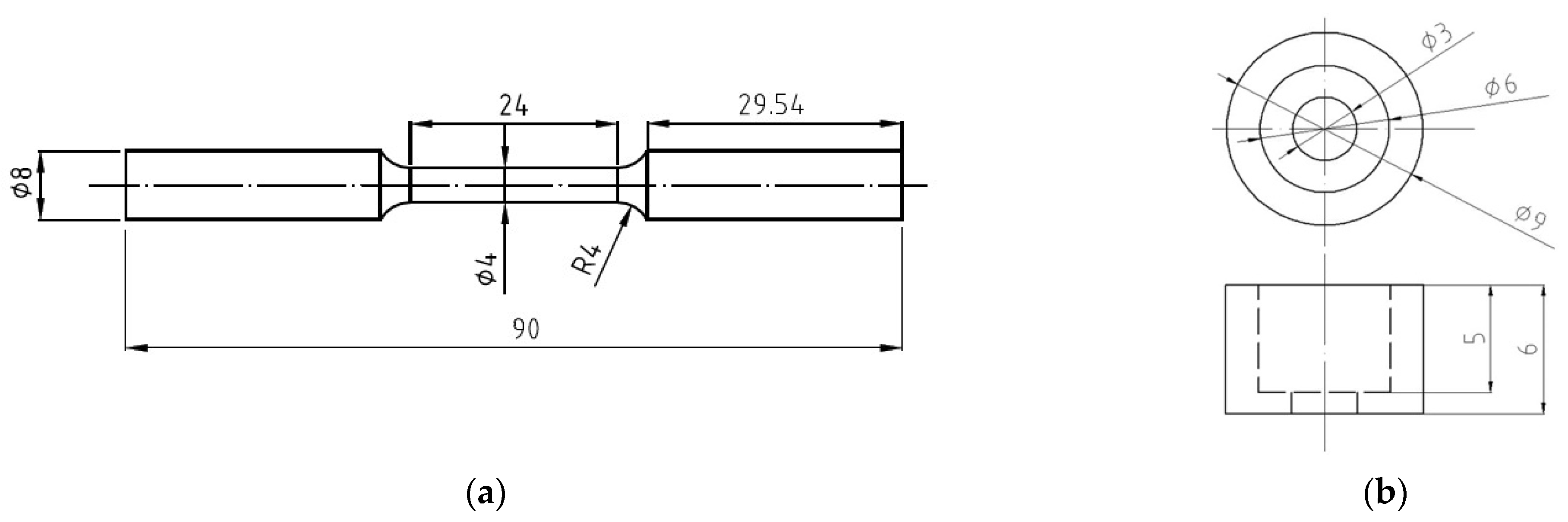
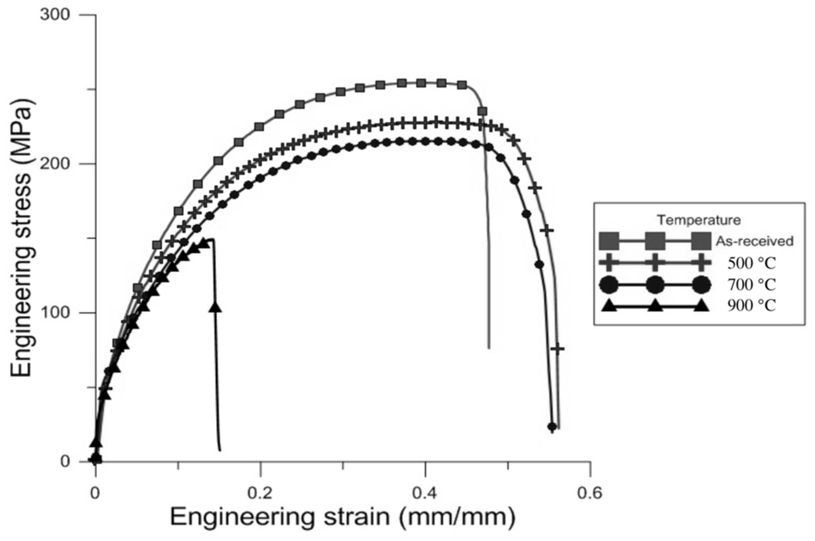
2.2. Mechanical Property

The annealed specimens from Group t were tested using a universal tensile testing machine (Insight 5 kN, MTS Co., Minneapolis, MN, USA). Young’s modulus (E) was calculated using the displacement-force curve, according to the ASTM-E111 standard. The strength coefficient (K) and the strain hardening exponent (n) were calculated using the true stress–strain curve and the power law:
σ = K ε n

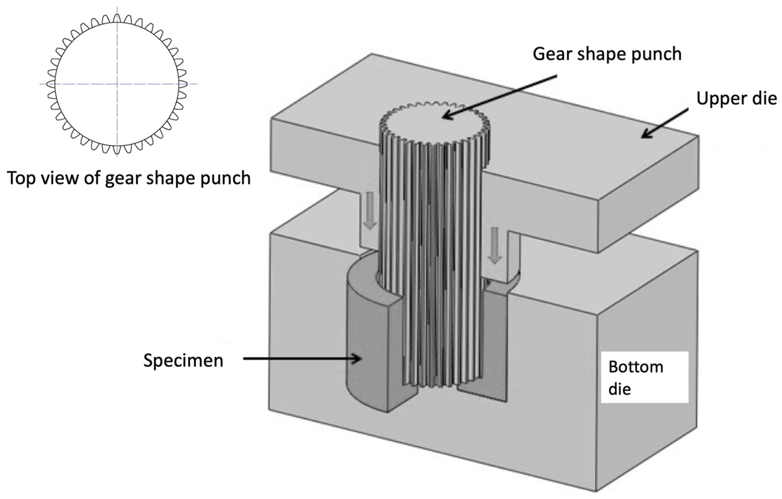
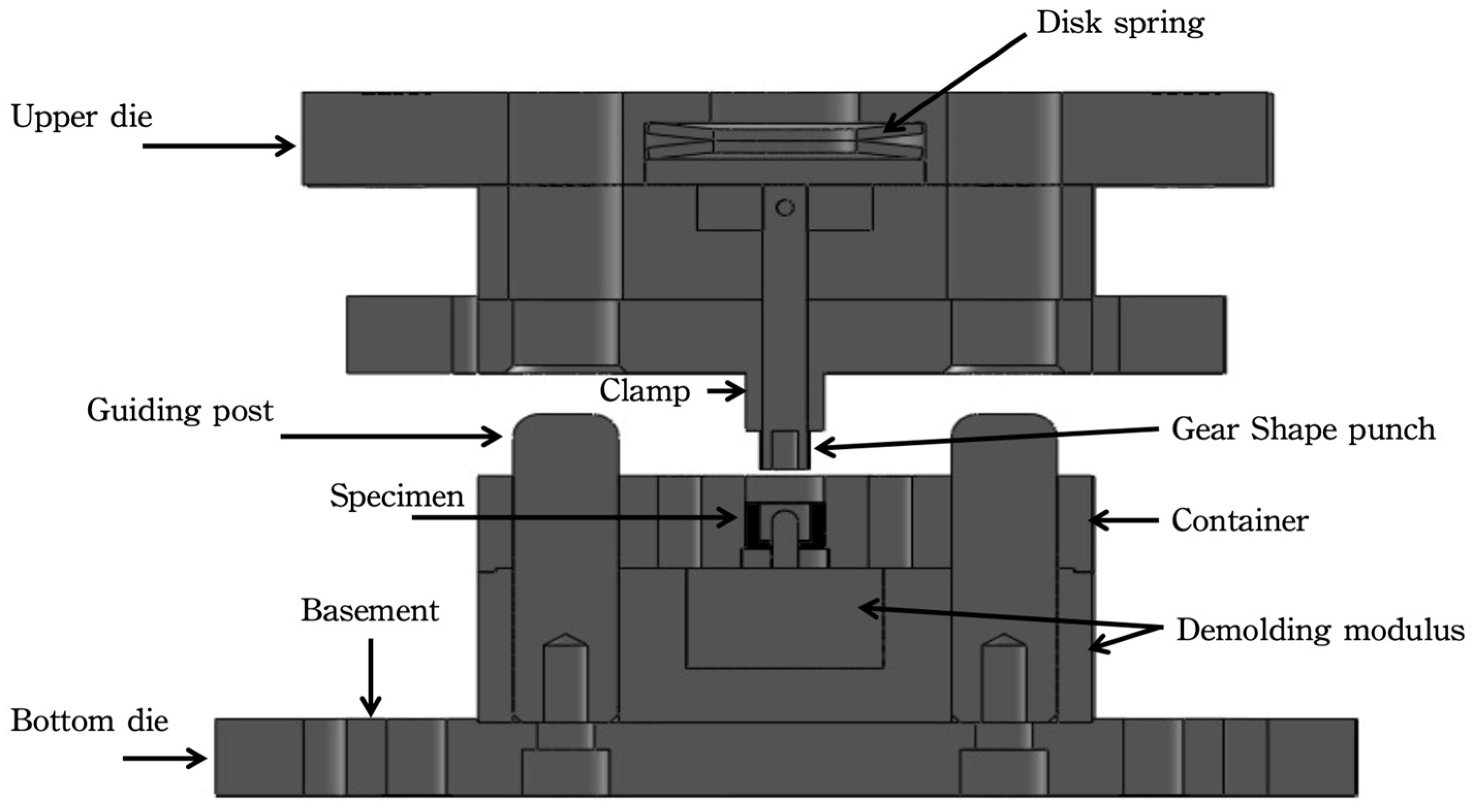
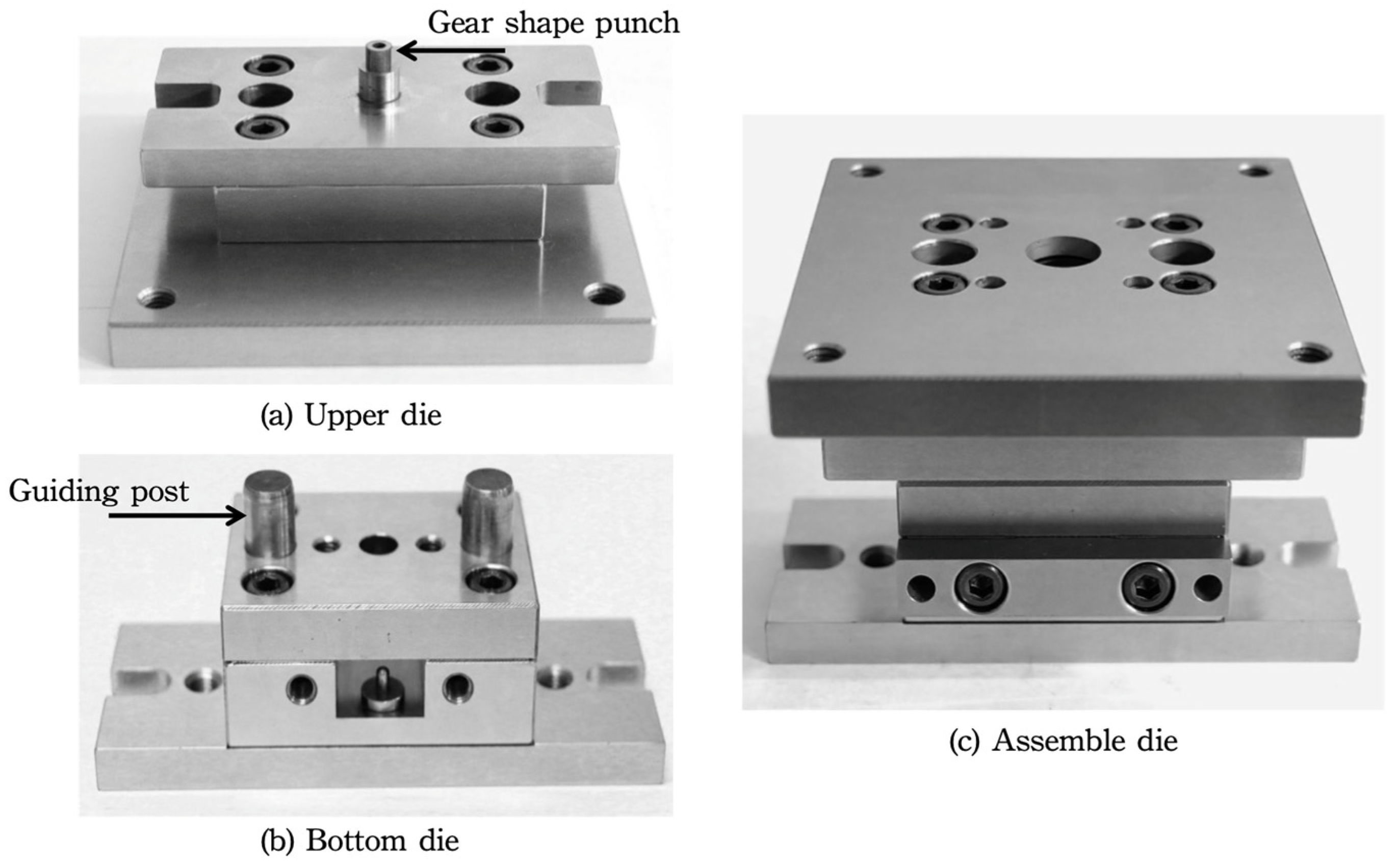
2.3. Internal Gear Specification and Die Design

Figure 2 shows that the punch shape is a spur gear with 36 teeth. The module is 0.15 because the pitch diameter is 5.4 mm. The tip and root diameters are 5.7 and 5.025 mm, respectively. The specifications are listed in Table 1. The material is forced to flow into the tooth cavity by pressure from the upper die and the maximum depth of the tooth cavity is 0.675 mm.
The assembled die consists of an upper die and a bottom die. The upper die has a clamp, a gear shape punch and a disk spring. The bottom die consists of a container, a basement, two guiding posts and a demolding module, as shown in Figure 3. All components of the assembled die are made of JIS SKD-11 tool steel. The most important component of the die set assembly is the gear shape punch. The punch is machined using electrical discharging machining (EDM). The container has a die cavity and a hole through which the product is ejected during demolding. A pre-shape specimen is placed into the die cavity. The dimensions of the pre-shape specimen are shown in Figure 1b.

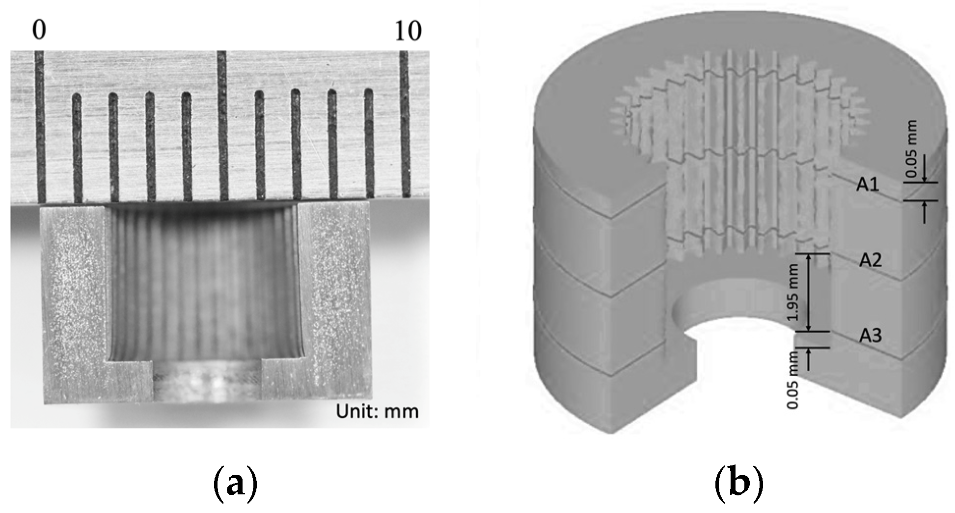
2.4. Gear Filling Rate

The filling rate is defined as the average of the three measured areas that are shown in Figure 4, divided by the area of the actual tooth of the die cavity (At) as:
FR ( % ) = A i 3 A t × 100 % ,   ( i = 1 , 2 , 3 )
where A i is the ith measured area of the gear. In this study, the squeezed part is cut by a wire electric discharge machine (AccuteX Co., Taichung, Taiwan), as shown in Figure 4b, and the contours of the three cross sectional profiles, A1, A2 and A3, were measured. The area of each cross-sectional profile and the tooth profile of the die cavity were determined using a profile measurement machine (EM-2.5D, Mimn Taiy Co., Taichung, Taiwan).

2.5. Hardness Measurement

The hardness distribution of grain in the miniatured gear was measured by a Vickers hardness test (401MVDTM, Wilson Wolpert, Taipei, Taiwan). Half of the gear was polished and indented by a tetragonal diamond indenter with a face angle of 136° under a load of 500 g exerted during 15 s. The hardness value ( H v ) can be calculated by the following equation:
H v = P A = 2 P D 2 s i n θ = 1854.4 P D 2
where A denotes the permanent indentation area on the test surface and P (gf) is the load. D (μm) is the average length of the two diagonals of the indentation and θ is the face angle of diamond.

3. Results and Discussion

3.1. Manufactured Components and Assembled Die

Figure 5 shows the details of the assembled die, including the upper die, the bottom die and the gear shape punch. The experimental process has four stages. The bottom die was affixed to the base of the experimental machine and the annealed specimen was inserted into the die cavity. The gear shape punch was then mounted on the upper die and fixed on the connector using a punch clamp. The connector was screwed to a load cell with a maximum compressive load of 20 tons (NTS Co., Miaoli County, Taiwan) to record the extrusion force (Fs) and was pressed by the ram of the hydraulic cylinder (20 tons, Giant-red-wood International Co., Taoyuan, Taiwan). The upper and bottom dies were aligned using guiding posts. The ram speed and the effective stroke were set before the cold lateral extrusion process. For this study, the ram speed and the effective stroke are 0.01 mm/s and 0.85 mm, respectively. Part of the material around the inner surface of the pre-shape specimen flows into the gear cavity as the upper die presses down to form the internal gear shape. The demolding module is used to remove the final product.

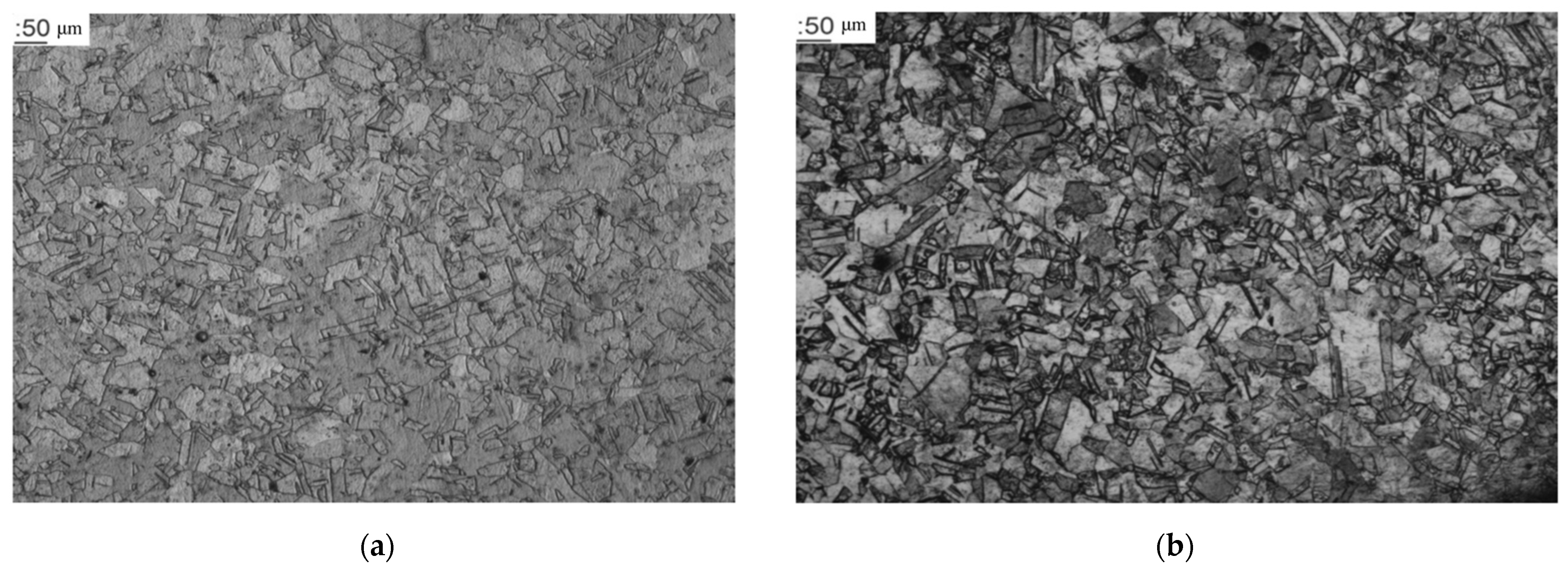
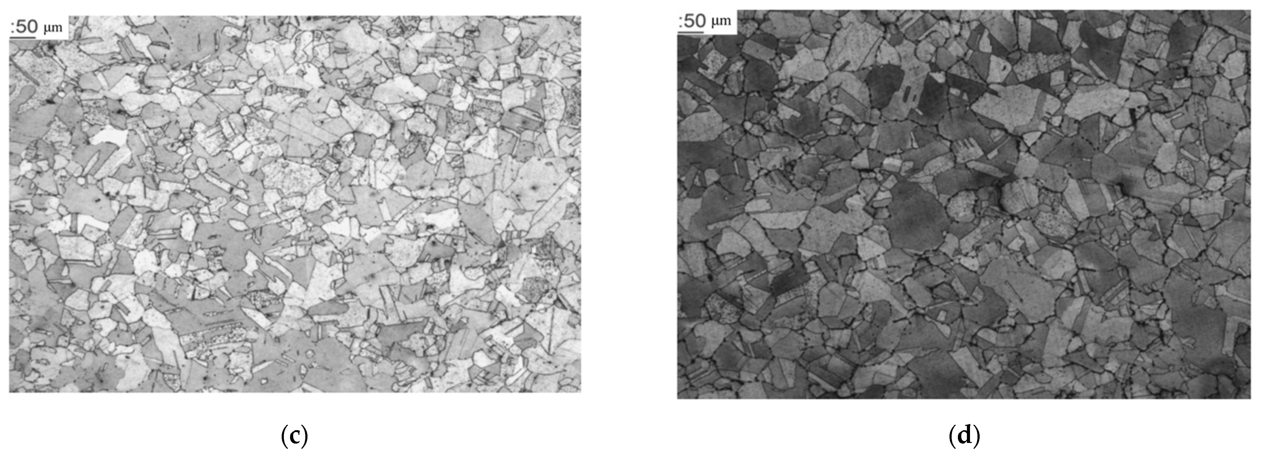
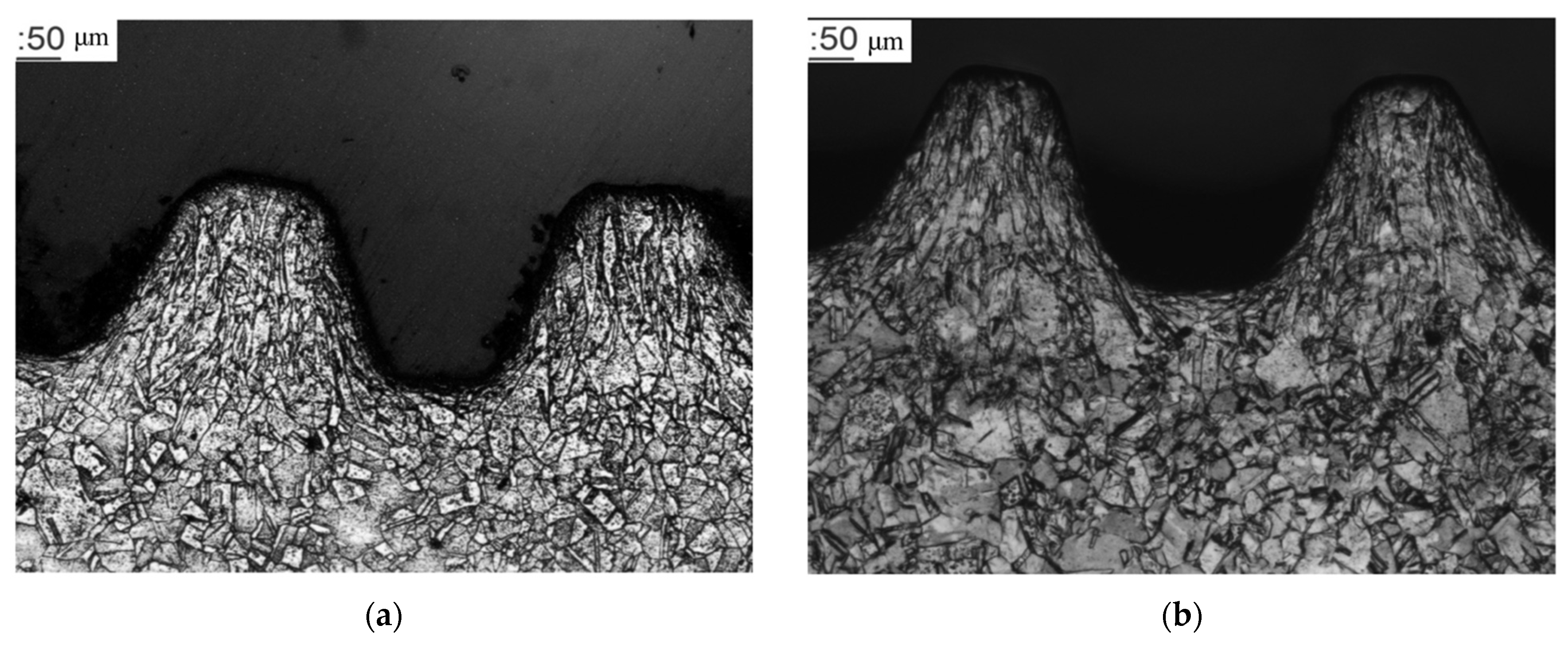
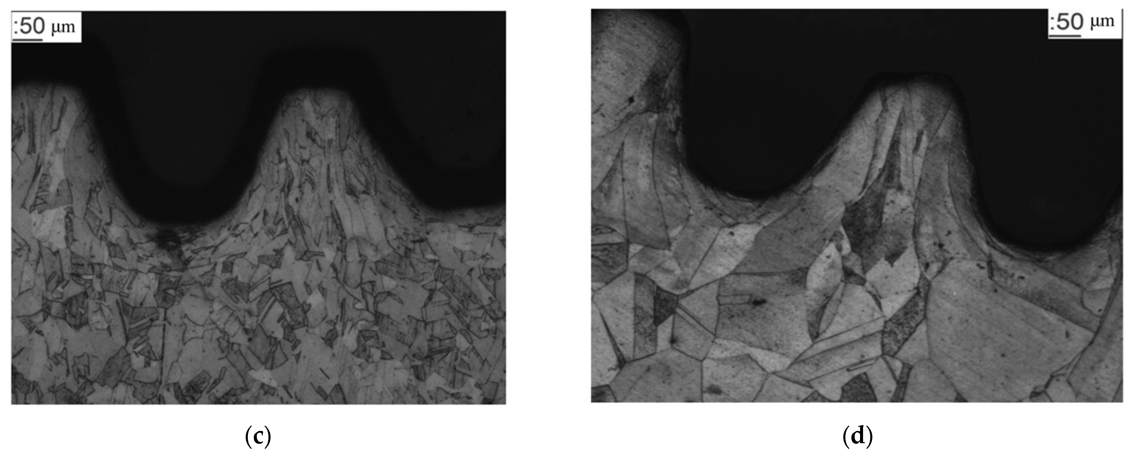
3.2. Microstructural Observation and Grain Size Effect

Figure 6 shows the microstructure of Group m specimens as received and those that are annealed at different temperatures. The relationship between the average initial grain size and the annealing temperature is shown in Table 2. The initial grain size varies from 22.3 μm to 95.5 μm. The higher the annealing temperature, the larger is the initial grain size. This initial grain formation trend agrees with the results of previous studies [9,10,14,17]. An annealing temperature of 500 °C precipitates the growth of initial grains that are 3 μm larger than those for the as received specimens but ductility increases, as shown in figure.
Figure 7 presents the results of the tensile test in regard to different grain size. Annealing treatment enhances ductility, except for the annealing temperature of 900 °C. Comparing the grain size, the initial grains for the annealing temperature of 900 °C are three-times larger than those for an annealing temperature of 500 °C and it leads to decrease in elongation at break ( δ ) and tensile strength (TS). It was found that a grain size of 95.5 μm obtains the lowest ultimate strength and smallest engineering strain among the others.

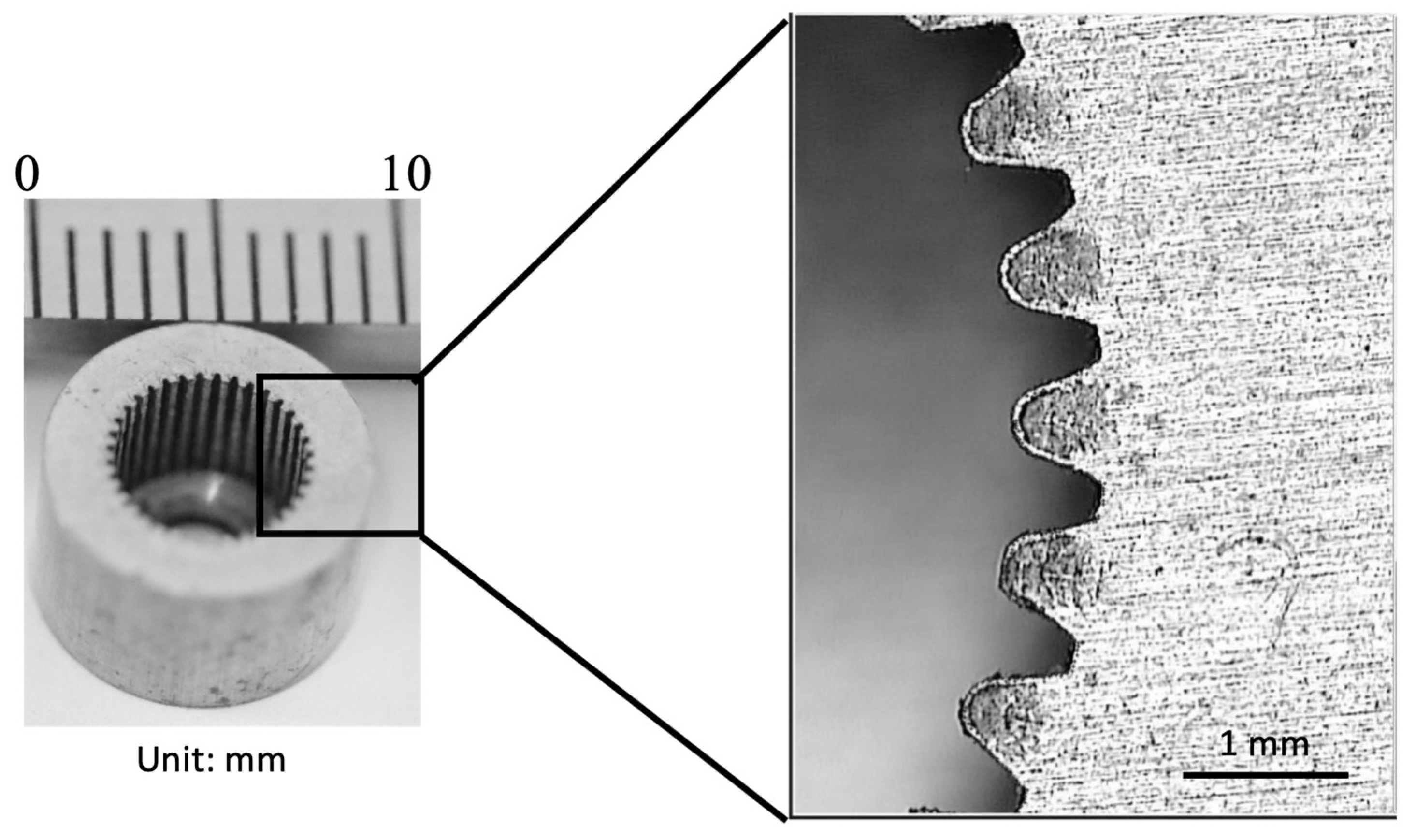
3.3. Experimental Result of Cup-Shaped Internal Gear

Figure 8 shows that the proposed cold lateral extrusion process microforms the cup-shaped internal gear. Figure 9 shows the grain shape and grain distribution in the cross section of the tooth. The grains are squeezed so the specimen is flat and elongated in the middle region but there is little grain refinement. Larger grains are more likely to cause grain refinement when the extrusion force or shear stress are large, but Figure 9d shows that there is no grain refinement. The initial grain size for the specimens for this study is between 22.3 µm and 95.5 µm, so the filling rate is 99.2 to 94.6%, but there is no grain refinement, so the copper alloy is highly resistant to grain refinement.

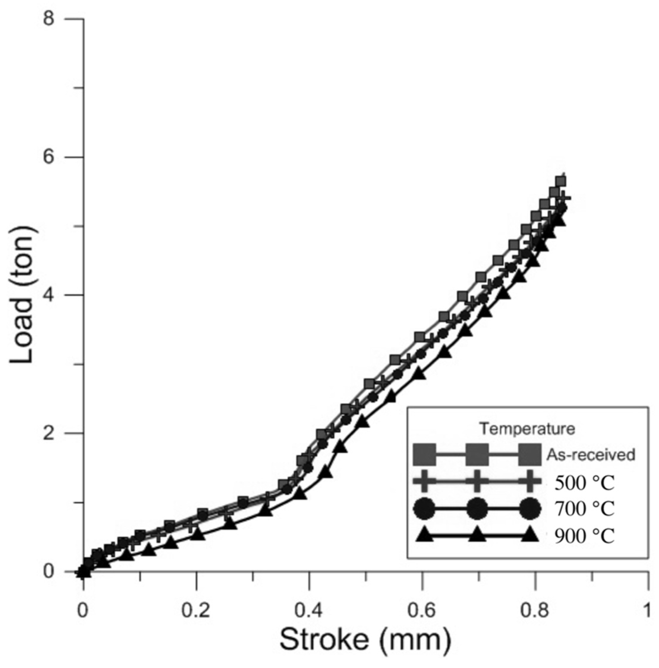
3.4. Grain Size Effect on Gear Filling Rate and Extrusion Force

The filling rate for the tooth cavity affects the integrity of the gear tooth profile and the efficiency of transmission. The filling rate defines the product yield. The results in Table 2 show the effect of initial grain size on the filling rate. The specimen that is annealed at a temperature of 500 °C has a maximum filling rate of 99.2% but a lower filling rate of 94.6% is achieved for the specimen that is annealed at a temperature of 900 °C.
In terms of the grain size point, the smaller the grain, the greater is the filling rate. The results in Table 2 show that the as received specimen has the smallest grain size of 22.3 µm but the filling rate is less. This is explained by deformability, as shown in Figure 7. The as received material is not so ductile as the material that has an initial grain size of 25.5 µm or 30.5 µm. The material that has an initial grain size of 95.5 µm is least elongated and decreases ductility so it has the lowest filling rate.
After reviewing the literature related to grain refinement, it can concluded that grain refinement increases the strength and decreases the ductility [19]. Grain refinement can be induced by high pressure torsion to increase tensile strength and results in uniform ductility [20]. Observing the grain size distribution in the tooth region, grain refinement is rarely found. This reveals that the initial grain size has the greatest effect on the filling rate because no grain refinement occurs during the internal gear extrusion process. A larger grain also produces a lower filling rate so flow into the tooth cavity is restricted.
This study determines the effect of initial grain size on the extrusion force so the effective stroke is a constant. Figure 10 shows the curves for stroke extrusion force. The highest and lowest extrusion force are for the as received material and the specimen that is annealed at a temperature of 900 °C, as shown in Table 2. The specimen that is annealed at a temperature of 500 °C has a larger initial grain size so the filling rate is greater, but the extrusion force is less than that for the as received material. This shows that the thin sheet manufacturing method for as received material causes residual stress or accumulative stress, so the strain hardening component is greater, and the material is less deformable. Except for the as received material, the extrusion force increases as the initial grain size increases because no grain refinement occurs.

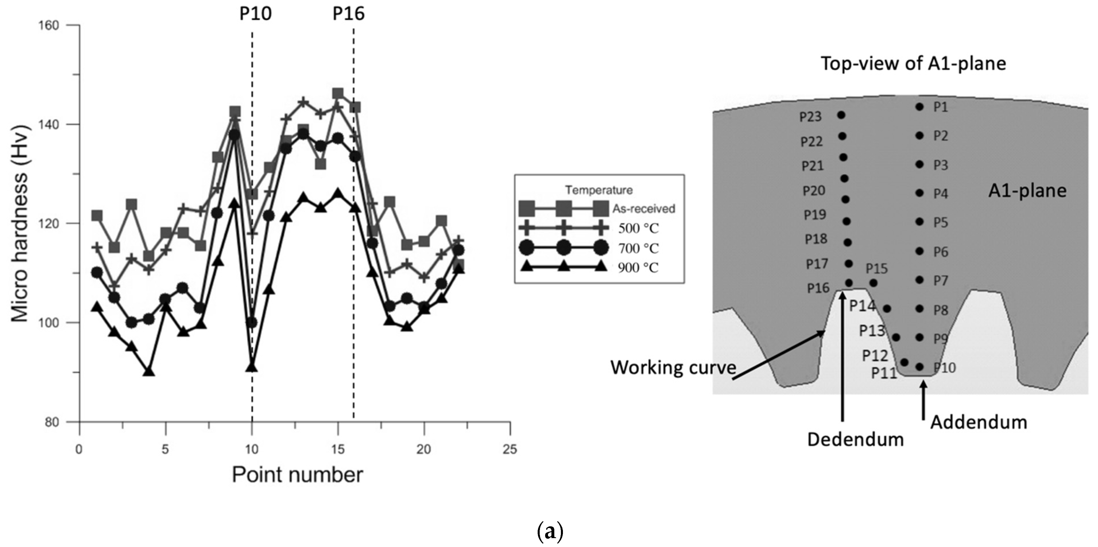
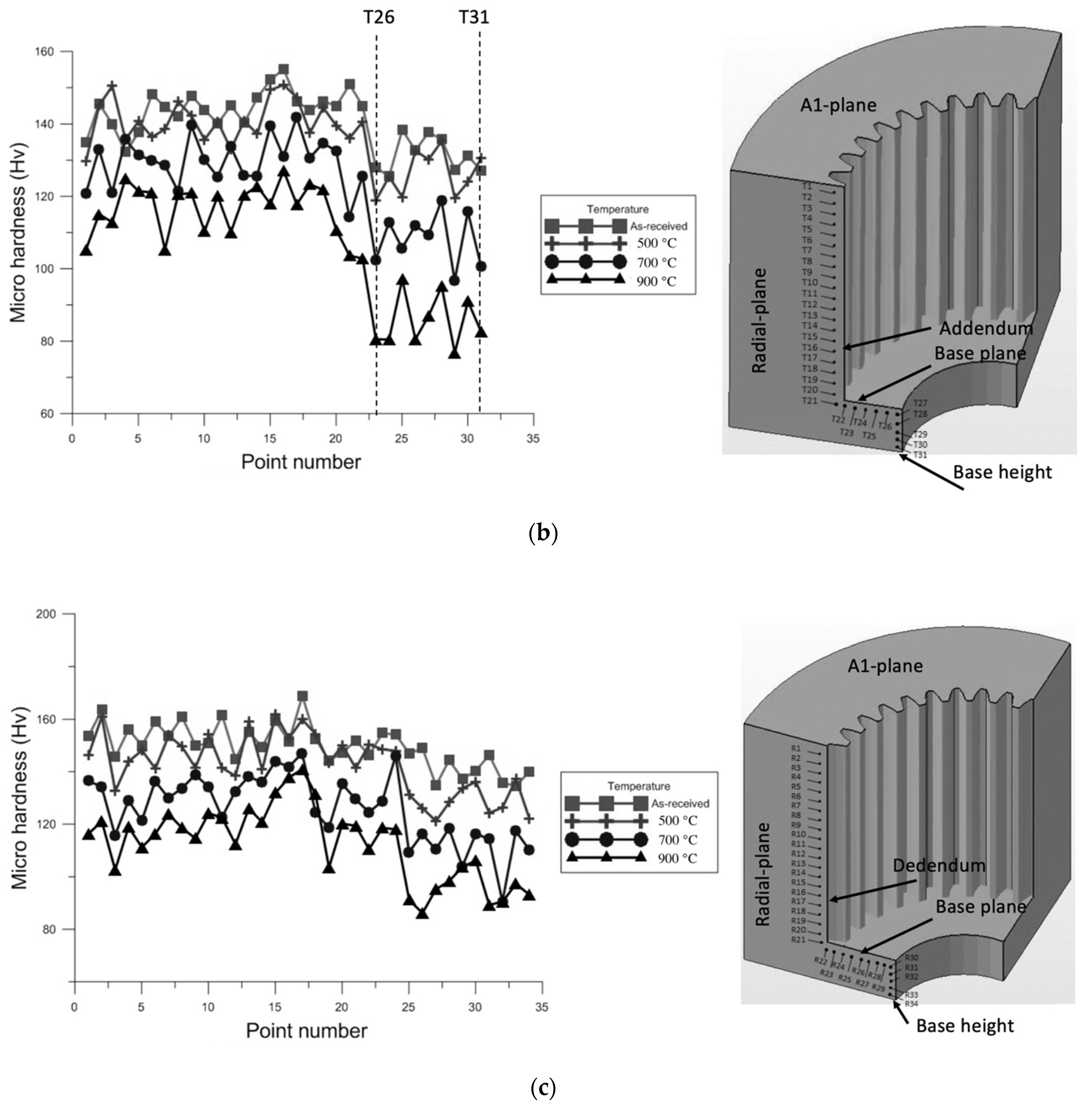
3.5. Hardness Distribution and Revolution

Table 2 lists the hardness of the initial grains, and the results show that the as received material has the highest hardness value of 108 Hv. Except for the as received material, the hardness decreases as the initial grain size increases.
The obtained cup-shaped internal gears were cut by a wire EDM along the radial and axial planes, as shown in Figure 11. The cut planes were indented to measure the hardness along the edge of the tooth profile toward the inside at a distance of 0.2 mm, and the distance between each point is 0.2 mm.
Figure 11a shows that the distribution of the hardness in the A1 plane of the tooth is not homogeneous, so the hardness value gradually increases from the addendum (P10) to the dedendum (P16). The plastic deformation in the A1 plane of the gear tooth gradually increases from the addendum (P10) to the dedendum (P16), so there is a greater degree of cold work hardening. Figure 11b,c shows the distribution of the hardness in the radial plane. Both figures show that the hardness along the addendum and the dedendum edge is approximately homogenous, possibly because the distribution of the plastic deformation in the middle of the gear tooth is homogeneous from the addendum and the dedendum, so the degree of cold work hardening is homogeneous. These results are in good agreement with the result for a spur bevel gear that is formed by cold rotary forging [21]. The hardness of as received and the specimen that is annealed at a temperature of 500 °C is high but the specimen that is annealed at a temperature of 900 °C has the lowest hardness value.

4. Conclusions

This study determines the material behavior of copper alloy C1100 using a lateral extrusion process. A novel cup-shaped internal gear extrusion die set assembly is used to determine the effect of the initial grain size on the mechanical properties and the die filling rate. The material that is annealed at a temperature of 500, 700 and 900 °C has a respective initial grain size of 25.5, 30.5 and 95.6 µm. The specimen with an initial grain size of 25.5 µm is more ductile and forms a cup-shaped internal gear with the highest filling rate of 99.2%. A larger initial grain size results in a lower filling rate because no grain refinement occurs. For the annealed treated specimens, the Vickers hardness and the extrusion force decrease as the initial grain size increases. The hardness along the addendum and the dedendum edges is approximately homogeneous but gradually becomes less homogeneous along the edge of the tooth profile from the addendum to the dedendum.

Author Contributions

Conceptualization, C.-P.J. and Y.E.; methodology, C.-P.J.; validation, C.-P.J., P.-S.C. and C.-C.C.; formal analysis, C.-P.J.; investigation, P.-S.C.; resources, C.-P.J. and Y.E.; data curation, P.-S.C.; writing—original draft preparation, C.-P.J.; writing—review and editing, C.-P.J.; visualization, C.-P.J. and Y.E.; supervision, C.-P.J.; project administration, C.-P.J. and Y.E.; funding acquisition, C.-P.J. All authors have read and agreed to the published version of the manuscript.

Funding

This research was funded by the Ministry of Science and Technology (MOST), Taiwan, grant number 105-2923-E-150-001-MY3, 107-2221-E-027-130-MY3 and 110-2622-E-027-007.

Data Availability Statement

The data presented in this study are available on request from the corresponding author.

Acknowledgments

The authors are grateful for technical support by Hanbird Technological Company, Taiwan.

Conflicts of Interest

The authors declare no conflict of interest.

References

  1. Han, J.; Zhu, Y.; Xia, L.; Yuan, B.; Wu, L. Influences of control error and setting error on machining accuracy of internal gearing power honing. Int. J. Adv. Manuf. Technol. 2019, 100, 225–236. [Google Scholar] [CrossRef]
  2. Singh, A.; Kahraman, A.; Ligata, H. Internal gear strains and load sharing in planetary transmissions: Model and experiments. J. Mech. Des. 2008, 130, 072602. [Google Scholar] [CrossRef]
  3. Gupta, K.; Jain, N.K. Comparative study of wire-EDM and hobbing for manufacturing high-quality miniature gears. Mater. Manuf. Process. 2014, 29, 1470–1476. [Google Scholar] [CrossRef]
  4. Chaubey, S.K.; Jain, N.K. Capabilities evaluation of WSEM, milling and hobbing for meso-gear manufacturing. Mater. Manuf. Process. 2018, 33, 1539–1548. [Google Scholar] [CrossRef]
  5. Chen, Y.; Hu, Y.; Lyu, Y.; He, G. Development of a form milling method for line gear: Principle, CNC machine, cutter, and testing. Int. J. Adv. Manuf. Technol. 2020, 107, 1399–1409. [Google Scholar] [CrossRef]
  6. Ku, T.-W. A Study on Two-Stage Cold Forging for a Drive Shaft with Internal Spline and Spur Gear Geometries. Metals 2018, 8, 953. [Google Scholar] [CrossRef] [Green Version]
  7. Fu, M.; Chan, W. A review on the state-of-the-art microforming technologies. Int. J. Adv. Manuf. Technol. 2013, 67, 2411–2437. [Google Scholar] [CrossRef]
  8. Eichenhueller, B.; Egerer, E.; Engel, U. Microforming at elevated temperature-forming and material behaviour. Int. J. Adv. Manuf. Technol. 2007, 33, 119–124. [Google Scholar] [CrossRef]
  9. Chen, C.-C.; Jiang, C.-P. Grain size effect in the micro-V-bending process of thin metal sheets. Mater. Manuf. Process. 2011, 26, 78–83. [Google Scholar] [CrossRef]
  10. Chen, C.-C. Grain-size effect on the forging formability of mini gears. Int. J. Adv. Manuf. Technol. 2015, 79, 863–871. [Google Scholar] [CrossRef]
  11. Zheng, W.; Wang, G.; Lin, X.; Tang, B.; Huang, L.; Qing, W.; Sun, Y. The Experimental Investigation of Size Effect on Micro-cylinder Deformation in Coining Process. Mater. Manuf. Process. 2014, 29, 687–690. [Google Scholar] [CrossRef]
  12. Nanda, T.; Kumar, B.R.; Sharma, S.; Singh, V.; Pandey, O. Effect of thermal cycling process parameters on recrystallization kinetics for processing of fine-grained pure copper. Mater. Manuf. Process. 2017, 32, 34–43. [Google Scholar] [CrossRef]
  13. Yang, M.; Shimizu, T. High-density energy-assisted microforming for fabrication of metallic devices. Mater. Manuf. Process. 2015, 30, 1229–1234. [Google Scholar] [CrossRef]
  14. Chang, X.; Xu, K.; Xie, D.; Luo, S.; Shu, X.; Ding, H.; Zheng, K.; Li, B. Microforging technique for fabrication of spherical lens array mold. Int. J. Adv. Manuf. Technol. 2018, 96, 3843–3850. [Google Scholar] [CrossRef]
  15. Nanthakumar, S.; Rajenthirakumar, D.; Avinashkumar, S. Influence of temperature on deformation behavior of copper during microextrusion process. Proc. Inst. Mech. Eng. Part C J. Mech. Eng. Sci. 2020, 234, 1797–1808. [Google Scholar] [CrossRef]
  16. Jafarzadeh, H.; Faraji, G.; Dizaji, A. Analysis of lateral extrusion of gear-like form parts. J. Mech. Sci. Technol. 2012, 26, 3243–3252. [Google Scholar] [CrossRef]
  17. Matsumoto, R.; Tanaka, S.; Utsunomiya, H. Enhancement of plastic flow in lateral direction by torsional oscillation in upsetting and lateral extrusion. J. Mater. Process. Technol. 2022, 299, 117369. [Google Scholar] [CrossRef]
  18. Freitas, B.J.M.; Otani, L.B.; Kiminami, C.S.; Botta, W.J.; Bolfarini, C. Effect of iron on the microstructure and mechanical properties of the spray-formed and rotary-swaged 319 aluminum alloy. Int. J. Adv. Manuf. Technol. 2019, 102, 3879–3894. [Google Scholar] [CrossRef]
  19. Zheng, J.-Y.; Shi, S.; Fu, M. Progressive microforming of pin-shaped plunger parts and the grain size effect on its forming quality. Mater. Des. 2020, 187, 108386. [Google Scholar] [CrossRef]
  20. Chen, C.-C. Experimental study on formability of phosphor bronze thin sheet in micro bead forming process. Int. J. Adv. Manuf. Technol. 2016, 84, 1897–1905. [Google Scholar] [CrossRef]
  21. Zhuang, W.; Hua, L.; Han, X.; Dong, L. Distribution of microstructure and vickers hardness in spur bevel gear formed by cold rotary forging. Adv. Mech. Eng. 2014, 6, 809276. [Google Scholar] [CrossRef] [Green Version]
Figure 1. The dimensions of the specimen for (a) tensile test and (b) the internal gear forming experiment (units are mm).
Metals 12 00826 g001
Figure 2. The relationship between the position of the gear shape punch and other components.
Metals 12 00826 g002
Figure 3. Details of the cup-shaped internal gear lateral extrusion die assembly of CAD model.
Metals 12 00826 g003
Figure 4. The measurement position for each cross-sectional profile (a) WEDM cut of final product and (b) measurement position.
Metals 12 00826 g004
Figure 5. Details of manufacture components including (a) upper die with a gear shape punch, (b) bottom die with a pair of guiding post and (c) the assembly of cup-shaped internal gear lateral extrusion die.
Metals 12 00826 g005
Figure 6. Microstructural images of initial grain size for different annealing temperatures: (a) as-received (b) 500 °C, (c) 700 °C and (d) 900 °C.
Metals 12 00826 g006aMetals 12 00826 g006b
Figure 7. Engineering stress–strain curves for the different grain sizes.
Metals 12 00826 g007
Figure 8. The experimental result for the cup-shaped internal gear and the tooth profile measurement.
Metals 12 00826 g008
Figure 9. Microstructural image of the deformed internal gear for specimens that are annealed at (a) As received, (b) 500 °C, (c) 700 °C and (d) 900 °C.
Metals 12 00826 g009aMetals 12 00826 g009b
Figure 10. Curves for the stroke-extrusion force.
Metals 12 00826 g010
Figure 11. The distribution of the Vickers hardness in the A1 plane (a) and the radial plane (b,c) of the gear tooth.
Metals 12 00826 g011aMetals 12 00826 g011b
Table 1. Specifications of the cup-shaped internal spur gear.
ParametersValue
Number of teeth (N)36
Module (m)0.15
Pressure angle (α)20°
Pitch diameter (Dp)5.4 mm
Tip diameter (Dt)5.7 mm
Root diameter (Dr)5.025 mm
Number of teeth (N)36
Table 2. Initial grain size and the mechanical properties of the annealed specimens.
ATdi (μm)E (GPa)TS (MPa)δ (%)K (MPa)nHvFs (ton)FR (%)
As-received22.3116.14258.247.36930.569108 ± 2.75.8 ± 0.1498.1
500 °C25.5110.14235.557.86340.55196 ± 4.15.5 ± 0.2299.2
700 °C30.5106.4217.854.26050.54388 ± 5.75.3 ± 0.1198.8
900 °C95.598.65147.515.15050.51771.9 ± 3.55.2 ± 0.3594.6
Publisher’s Note: MDPI stays neutral with regard to jurisdictional claims in published maps and institutional affiliations.

