Article

Temperature Field Evolution of Seeding during Directional Solidification of Single-Crystal Ni-Based Superalloy Castings

1
School of Materials Science and Engineering, Xiangtan University, Xiangtan 411105, China
2
Key Laboratory of Advanced High Temperature Structural Materials, AECC Beijing Institute of Aeronautical Materials, Beijing 100095, China
3
State Key Laboratory of Solidification Processing, Northwestern Polytechnical University, Xi’an 710072, China
*
Authors to whom correspondence should be addressed.
These authors contributed equally to this work.
Metals 2022, 12(5), 817; https://doi.org/10.3390/met12050817
Submission received: 3 April 2022 / Revised: 30 April 2022 / Accepted: 6 May 2022 / Published: 9 May 2022
(This article belongs to the Topic Single-Crystal Ni-Based Alloys)

Abstract

:
By combined numerical simulations and unidirectional solidification experiments, the temperature field evolution of seeding for nickel-based single-crystal superalloys was studied. At the steady state, the position of the mushy zone in the seed moves down as the melt is poured into the mold. The holding time required for the temperature field of the seed segment to reach the steady state is less for seeds with casting than for those without casting. The holding time required to completely eliminate randomly oriented broken dendrites in the melt-back zone is much longer than that required for the temperature field to achieve a steady state. A short incubation stage is required before the temperature field evolution process; then, the migration rate of the isotherm gradually increases until it is the vicinity of the withdrawal rate. Finally, the effect of temperature field evolution on the formation of stray grains in seed segments is discussed.

1. Introduction

Nickel-based single-crystal (SX) superalloys are widely used for the turbine blades and vanes in aero-engines, due to their excellent comprehensive high-temperature properties [1,2]. With the continuous requirements for improved thrust-to-weight ratios in aero-engines, the turbine inlet temperature has significantly increased over the past few decades [3]. Therefore, hollow, ultra-cooled blades with more complex structures and lower minimum wall thicknesses have gradually become the development trend for advanced aero-engine blades. The mechanical properties of nickel-based superalloy SX casting exhibit obvious anisotropy [4,5,6,7], and the complexity of the blade structure leads to a more significant dependence of service performance on crystal orientation [8,9,10]. It has become the consensus that the precise three-dimensional control of crystal orientation (including primary and secondary orientations) is beneficial to improve the service life of advanced SX blades.
Directional solidification investment casting, combined with grain selection or seeding technology, is the main method for preparing SX blades [11,12,13,14]. The grain selection method has the advantages of having a simple process and a high yield when achieving SX casting, and is currently the most important method for preparing SX turbine blades [11,15]. However, when using this method, it is not possible to control the secondary orientation of SX blades due to the limitations of the grain selection mechanism [12]. Compared with the grain selection method, the most significant advantage of the seeding method is that the three-dimensional crystal orientation of SX casting can be controlled [14,16]. At the same time, some scientific research [17,18,19], such as that on competitive gran growth [20], has emerged that uses the seeding method to precisely control crystal orientation.
Since the seeding method was first proposed by Petrov in 1978 [21], the problem of the formation of solidification defects in the early directional solidification stages has prevented its widespread application in industrial production [22,23,24]. Extensive efforts have been devoted to investigating the mechanism of stray grains in the melt-back region of seeds [13,22,23,24,25,26,27,28]. In 1982, Salkeld et al. suggested that strictly controlling the melt-back ratio and the gap between the seed and the mold could result in the formation of stray grains and improve the yield rate [29]. In 2004, Stanford et al. found that extensive defect grains were nucleated at the seed surface, excluded from pinched-off secondary dendrite arms [22,30]. In 2005, D’Souza et al. proposed that solute-adjusted undercooling and the rapidly changing curvature of the solidification front at the seed surface were the main factors contributing to stray grain nucleation during the initial withdrawal stage [25]. Then, Yang et al. investigated the influence of casting parameters on stray grain formation using mesoscale numerical simulations and showed that the solute with adjusted undercooling was more highly sensitive to the solidification rate and the seed orientation than the thermal gradient [24]. Recently, Li et al. [16] reported that stray grains could nucleate at the gap between the un-melted seed and the mold. Montakhab et al. [31] and Hallensleben et al. [13] also found that some stray grains formed near the melt-back interface in the seed’s interior. However, the mechanism for the formation of stray grains in the melt-back region of seeding is still not clear.
The formation mechanism of stray grains in the melt-back region of the seed needs to be further determined to guide the implementation of measures to suppress solidification defects. Due to the difficulty of inserting thermocouples into the seed segment, the temperature field evolution process of seed segment, which is an important factor for the formation of stray grains, has not been specifically investigated. Numerical simulation is a powerful tool for studying the evolution of directional solidification temperature fields. For example, Szeliga et al. used a numerical simulation method realized using ProCAST software to study the grain evolution process during directional solidification, and the results showed a good match with the experimental results [32]. In this paper, the temperature field evolution and the microstructure of the seeding segment are investigated using a numerical simulation method and indirect experimental verification, and some insights are obtained that clarify the formation mechanism of stray grains in the melt-back region of seeding.

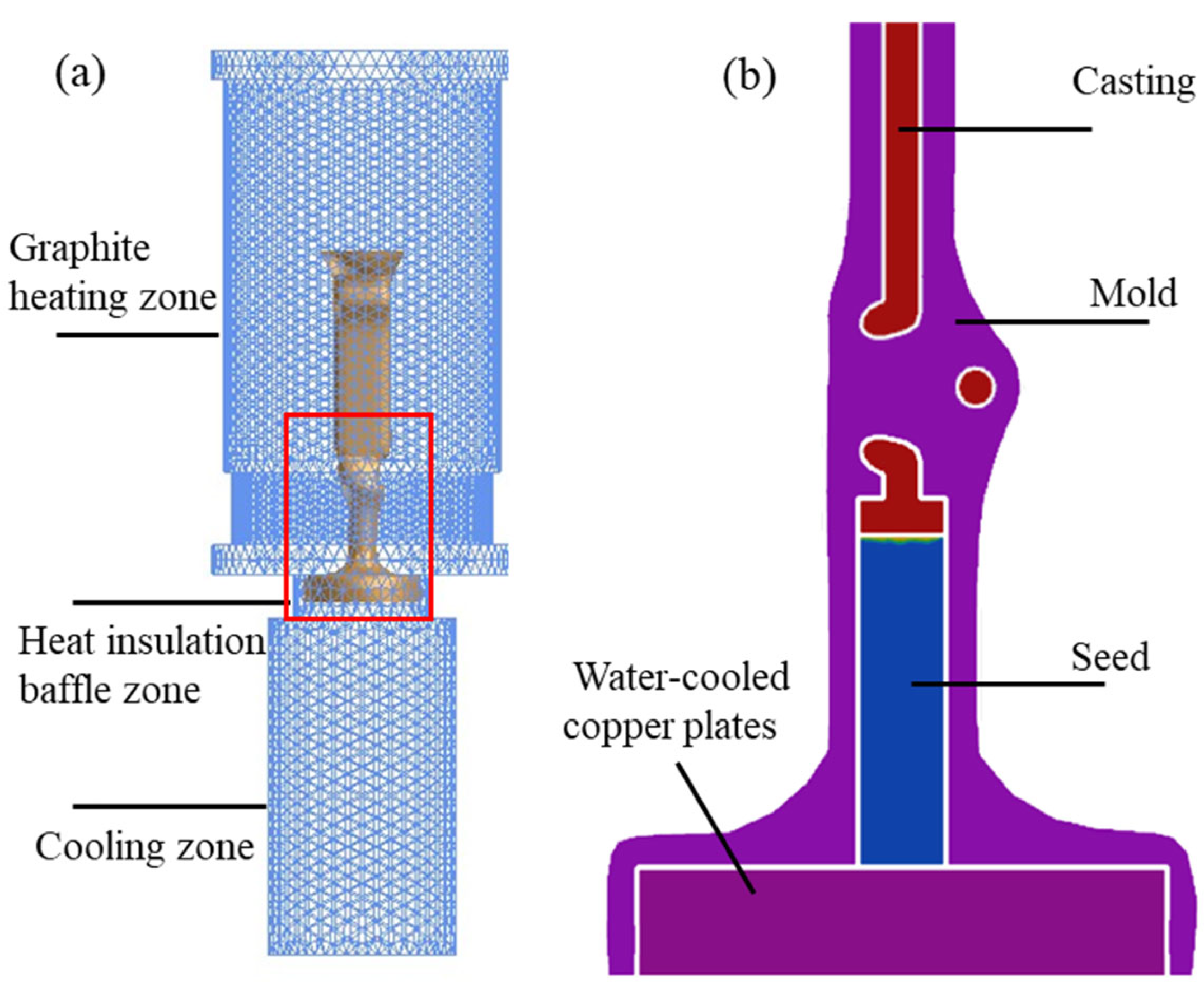
2. Simulation and Experiment

A third-generation nickel-based SX superalloy DD33 was used in this paper, the nominal composition of which (wt. %) was Ni- 2.5Cr- 9Co- 1.5Mo- 7W-6Al- 8Ta- 0.1Hf- 4Re- 0.2Ti and <0.02C. The thermophysical properties of the DD33 obtained by experimental measurements or thermodynamic calculations are listed in Table 1. The simulation software ProCAST ((a trademark of ESI Group, Paris, France) combined with the CAFÉ model was used to obtain the thermal profile of the seeding region. The directional solidification furnace was simplified into three parts: the graphite heating zone, the heat insulation baffle zone, and the cooling zone, and the dimensions of each part were modeled on the basis of an actual industrial-scale directional solidification furnace, as shown in Figure 1. While simulating the directional solidification, the furnace body was set as a closed vacuum space. To improve the calculation efficiency, the furnace body was divided into two-dimensional meshes, and the assembly, consisting of castings, seed, mold and water-cooled copper plates, was divided into three-dimensional meshes. The seed simulated in this study was cylindrical, with a size of Φ12 mm × 50 mm. When simulating the heating stage, according to the basic process of industrial production for SX blades, the temperature of the heating zone of the furnace body was increased from 900 °C to 1520 °C within 10 min at a constant heating rate. When the temperature of the furnace body reached 1520 °C, the holding stage was maintained for 20 min in order to obtain a stable temperature field, and then the furnace body was moved upward at a speed of 100 μm/s to simulate the directional solidification process. The initial conditions, the boundary conditions, and the interface heat transfer coefficients were set with reference to literature, with values as presented in Table 2. Finally, the influence of some key simulation parameters on the simulation results was also analyzed in this study.
To verify the accuracy of the simulation results, corresponding experiments were also carried out. A cylindrical SX rod with a size of Φ12 mm × 50 mm was used as the seed in this paper. In addition, the <001> direction of the seed was parallel to the cylinder axis. An industrial-scale directional solidification furnace was used to carry out the directional solidification. Firstly, the seed was placed in the seed segment of the mold, then the assembly was mounted on the water-cooled copper chill plate in the furnace body. Then, the position of the water-cooled copper plate was adjusted to ensure that part of the seed was located in the graphite heating zone, and the other part was located in the heat insulation baffle zone. At this time, the temperature of the furnace body was about 900 °C, and it was then heated to 1520 °C within 10 min, where it was held for a certain period of time. Finally, the mold was withdrawn from the graphite heating zone at a rate of 100 μm/s. After that, the longitudinal section of the seed crystal was ground, polished, and then etched with a solution of 10 mL HNO3, 20 mL HF and 30 mL C3H8O3. The microstructure was observed using a Leica DM-4000 light microscope (Leica, Wetzlar, Germany).

3. Results

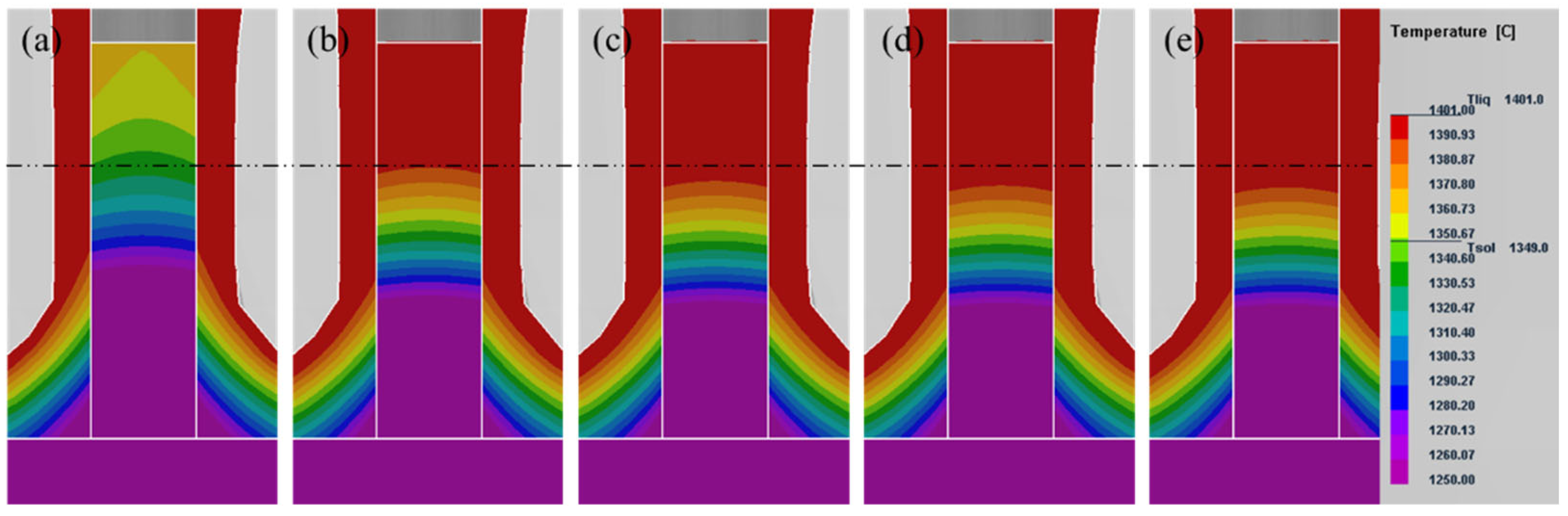
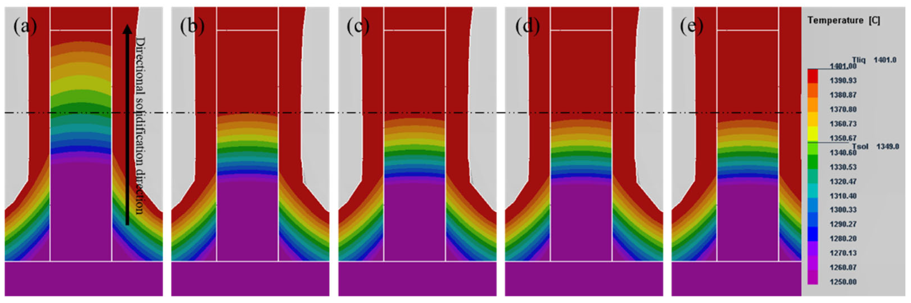
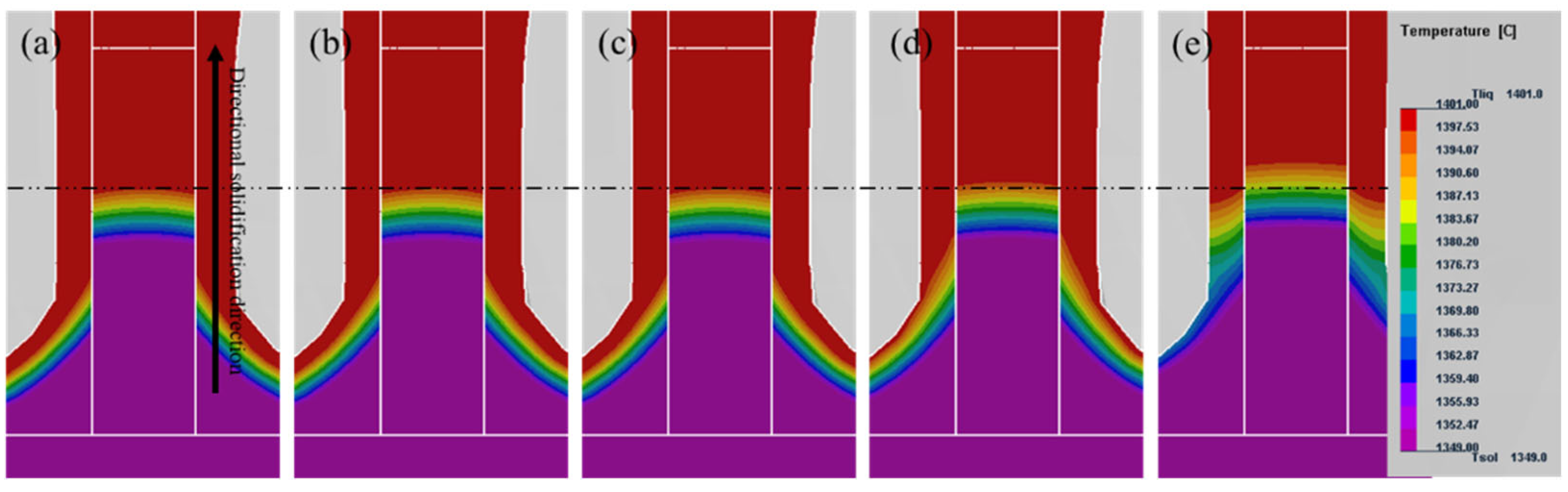
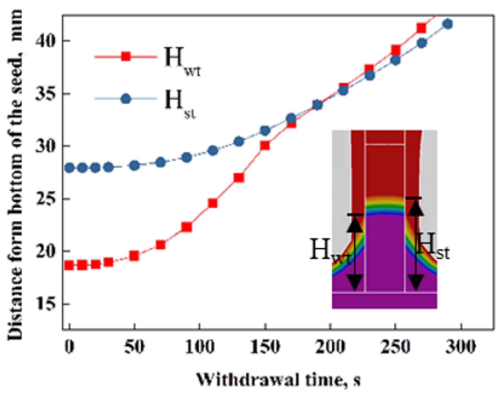
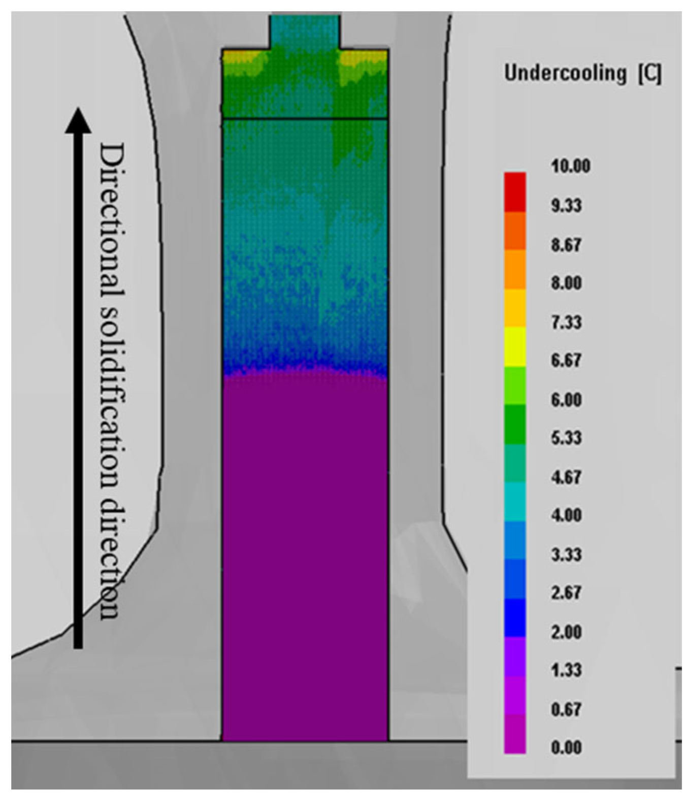
3.1. Simulation Results

Figure 2 shows the temperature field evolution process of the seed segment during the heating and holding stage. From Figure 2a, it can be seen that the top of the seed begins to melt during the heating stage, and the middle region of the seed has a fairly high temperature, above 1250 °C. The temperature of the mold is higher than that of the seed at the same horizontal position near the melt-back region. When the heating zone of the furnace body reaches the holding temperature of 1520 °C, the approximate one-third upper of the seed crystal is completely melted; however, the position of the middle temperature (1250 °C–1350 °C) region only moves down slightly, as shown in Figure 2b. From Figure 2c–e, it can be seen that the mushy zone moves down obviously during the initial holding stage. With the prolongation of the holding time, the downward movement speed of the mushy zone gradually decreases. Finally, the mushy zone remains in the middle region of the seed when the holding time reaches 8 min, which means that the temperature field of the seed reaches a steady state. It is worth noting that the temperature of the mushy zone is lower than that of the surrounding mold shell, so the melt-back interface of the seed exhibits a slightly convex morphology.
To further analyze the influence of the holding stage after melt pouring on the temperature field of the seed segment, the evolution process of the temperature field of the seed segment with the casting was simulated, and the results are shown in Figure 3. The evolution process of the temperature field in the seed segment is basically the same as that in the case without casting (Figure 2). The seed begins to melt before the furnace body reaches the holding temperature, and then the position of the mushy zone moves down and gradually reaches a steady state. The main differences occur in two aspects. Firstly, the position of the mushy zone moves down more than in the case without casting. Secondly, the holding time required for the position of the mushy zone of the seed crystal to reach a steady state decreases to 6 min. This indicates that the evolution of the temperature field accelerates after melt pouring, and that the seed continues to melt-back further.
The temperature field evolution process of the seed segment during the initial directional solidification stage is shown in Figure 4. Figure 4a shows the stable temperature field of the seed segment prior to moving the furnace body upward. In the early stage of directional solidification (as shown in Figure 4b), the temperature profiles basically do not change between the mold and the seed. Then, the temperature field begins to evolve, the evolution rate gradually accelerates (as shown in Figure 3c,d), and the migration rate of the liquidus temperature point in the mold becomes significantly higher than that in the seed. Therefore, the convex interface curvature of the solidification interface gradually decreases, and the interface morphology tends to be flat. During the subsequent directional solidification process, the solidified interface morphology is further transformed into a concave interface (not shown here).
To further clarify the evolution of the temperature field during directional solidification, Figure 5 shows the variation in the liquidus temperature point on the inner surface of the mold (Hwt) or the edge of the seed (Hst) from the bottom of the seed with withdrawal time. These data are obtained from simulation results. It can be seen that the distance between the liquidus temperature point and the bottom of the seed does not change significantly during the initial directional solidification stage. Afterwards, the distance increases slowly, indicating that the temperature field begins to gradually to evolve after a brief incubation during the directional solidification process. In addition, the change in distance between the liquidus temperature point on the seed and the bottom of the seed occurs later than the change in distance between the mold and the bottom of the seed. The migration rate of the solid–liquid interface in the initial withdrawal stage is also slower than that of the liquidus temperature point of the mold. Subsequently, the temperature field evolution rate (solid–liquid interface migration rate) gradually accelerates. After a withdrawal time of 150 s, the migration rate of the solid–liquid interface is basically same as that of the liquidus temperature point on the seed, which is approximately equal to the withdrawal rate. However, the temperature field evolution does not reach a completely steady state.
The thermal undercooling during directional solidification obtained on the basis of CAFE simulation with a withdrawal rate of 100 μm/s is shown in Figure 6. Since there is no phenomenon of melting and re-solidification, the undercooling below the melt-back interface is forcibly modified to 0. It can be seen that the thermal undercooling gradually increases during the initial withdrawal stage, and is not affected by the curvature of S/L interface. It should be noted that local, solute-adjusted undercooling is ignored by ProCAST combined with the CAFÉ simulation.

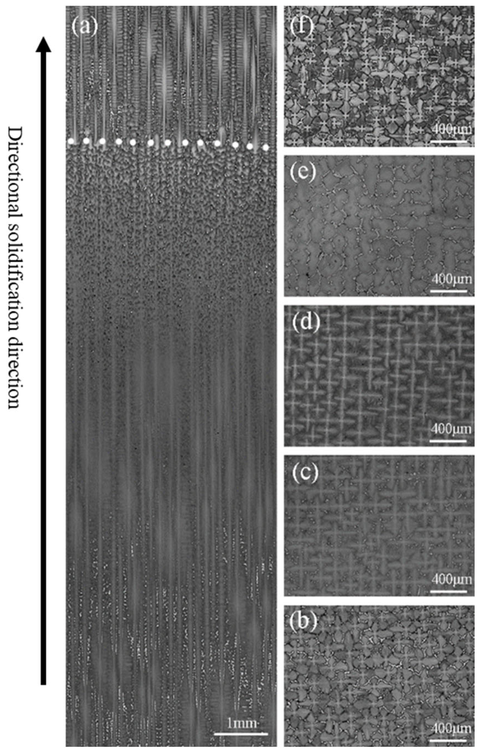
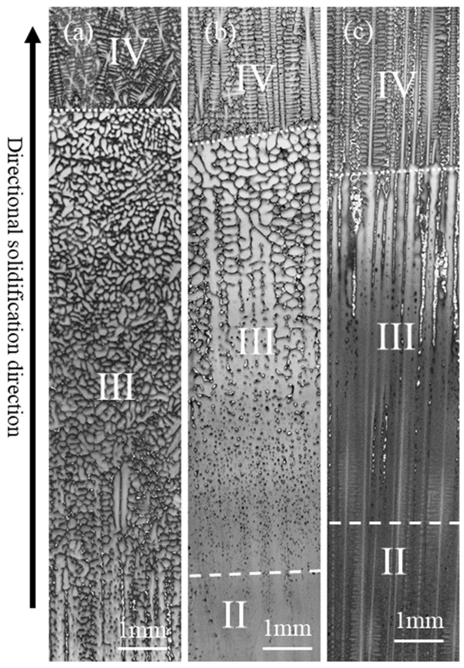
3.2. Experimental Results

The microstructure of the seed after directional solidification is shown in Figure 7. According to the microstructure characteristics of the longitudinal section (Figure 7a), the seed can be divided into four regions: firstly, zone I, with the original microstructure. This region is close to the bottom of the seed, and the temperature is maintained at a lower temperature during the preparation of the SX casting. Compared with the original microstructure (Figure 7b), there is no obvious change, and a lot of (γ + γ’) eutectics can be found, as shown in Figure 7c. Secondly, the heat-affected zone II. This zone is located above the zone with the original microstructure, and the boundary is not obvious. The zone is subjected to a relatively high temperature during the holding stage, according to the simulation results (Figure 2 and Figure 3), leading to the (γ + γ’) eutectics being completely or partially dissolved, as shown in Figure 7d. This indirectly indicates the accuracy of the simulation results. Thirdly, the mushy zone III. This zone is heated to between the liquidus and solidus temperatures during the heating and holding stages, and is bounded by the heat-affected zone through the formation of the initial melting microstructure. The top of the mushy zone contains a large number of re-solidified (γ + γ’) eutectics during directional solidification, as shown in Figure 7e. Finally, the completely melted zone IV. This zone is completely comprised of liquid during the later holding stage, and is bounded by the mushy zone at the melt-back interface, marked by dotted line in Figure 7a. After directional solidification, a typical columnar microstructure is re-formed, and a small amount of (γ + γ’) eutectics can be found, as shown in Figure 7f.
The effect of holding time on the microstructure in the mushy zone is shown in Figure 8. It can be seen that when the holding time is too short (as shown in Figure 8a), there are a large number of broken dendrites that have not been completely melted in the mushy zone. Therefore, a large number of randomly oriented stray grains can be found above the melt-back interface, resulting in the failure of the SX casting preparation. As shown in Figure 8b, appropriately prolonging the holding time could significantly reduce the number of stray grains formed above the melt-back interface, which is beneficial for improving the success rate of SX casting preparation. Furthermore, the broken dendrites can be completely melted by applying a sufficient holding stage, as shown in Figure 8c. This indicates that a sufficient holding (or standing) stage is beneficial to achieving SX casting using the seeding method.

4. Discussion

To eliminate the influence of melt pouring on the re-melting of seed, the height of the seed used in industry for preparing SX casting is usually several tens of millimeters [16,25,29]. The simulation results in this paper show that the position of the mushy zone in the seed segment moved down a little following a long standing time during which the melt was poured into the mold. This indicates that even if a long seed crystal is used for SX casting preparation, the effect of melt pouring on the re-melting zone of the seed cannot be completely eliminated. In particular, if the melt is directionally solidified during a short standing stage following melt pouring, this can result in a portion of the broken dendrites in the mushy zone not being completely melted, thus originating stray grains during directional solidification. Stanford et al. also reported finding randomly oriented broken dendrites in the mushy zone of the seed when applying a short holding stage prior to directional solidification [22]. Fortunately, after a long standing stage, the broken dendrites with random orientations near the melt-back interface were completely melted, ensuring the integrity of the SX casting during directional solidification. Comparing the simulation and experimental results, we further found that although the temperature field in the re-melting zone of the seed was able to reach a steady state in a short time, it took a much longer time for the broken dendrites to melt competely in the melt-back zone.
The boundary conditions played a crucial role in the accuracy of the results during the numerical simulation of the temperature field. Elliott and Pollock et al. [33] analyzed the effect of the boundary conditions on heat transfer during the directional solidification of HRS, and concluded that the surface emissivity of the mold was the most important factor affecting the heat dissipation of the castings. Because the heat transfer coefficient, both between the seed and the water-cooled copper plate and between the mold and the water-cooled copper plate, had no significant effect on the temperature field at the component segment, the values used by different scholars have been quite different [33,34,35]. At the same time, the value of the heat transfer coefficient between the mold and the casting has also differed in the literature [33,34,35]. However, in the initial stage of directional solidification, the heat transfer coefficient between the mold and seed, the heat transfer coefficient between the seed the water-cooled copper plate, and the heat transfer coefficient between the mold and water-cooled copper plate also have a significant impact on the evolution of the temperature field. Therefore, the influence of boundary conditions on the temperature field evolution in the melt-back zone was analyzed, and the results are shown in Figure 9. From Figure 9a, it can be seen that the heat transfer coefficient between the seed and water-cooled copper plate significantly affects the thermal profile evolution in the melt-back zone, e.g., with increasing heat transfer coefficient, HW0 and HS0 increase gently, while TP and HP increase sharply. The heat transfer coefficient, both between the mold and the casting and between the mold and chill plate, has a mild effect on the thermal profile in the melt-back region, as shown in Figure 9b,c.
By combining the simulation and experimental results, the general law of the temperature field evolution of seed segments can be summarized. First, a short incubation period is required before the evolution of the temperature field; second, the migration rate of the isotherm increases gradually during the initial temperature field evolution stage, rather than exhibiting a sudden jump to a constant value, like the withdrawal rate. Third, the convex shape of the solid–liquid interface gradually transitions to a flat interface, and then to a concave interface upon initial directional solidification, instead of there being an abrupt change in the interface morphology, as has been recognized for a long time. Therefore, the mechanism of stray grain formation as a result of a sudden change in the morphology of the solidification interface during the initial stage of solidification is debatable [24,25]. Recently, Hu et al. found that the gap between the mold and the seed, the surface roughness of the mold, and the original microstructure of the seed were the main factors determining the formation or not of stray grains [36]. In addition, the transformation of the solidification interface from a convex interface to a concave interface is only an important factor for the growth of the stray grains, rather than their nucleation.

5. Conclusions

The temperature field of the seed segment during the heating, holding, and directional solidification stages was investigated by means of numerical simulations combined with experiments. The upper part of the seed begins to melt during the heating stage, and the temperature field of the seed reaches a steady state after a short holding stage. However, it takes a much longer holding time for the microstructure of the seed segment to achieve a steady state than for the temperature field to do so. In the steady state, the seed can be divided into the original microstructure zone, the heat-affected zone, the mushy zone, and the completely melted zone. Even if the length of the seed reaches 50 mm, the melt pouring will cause the seed to melt back further. Furthermore, there is a short incubation stage prior to the temperature field evolution during the initial directional solidification stage. Then, the migration rate of the isotherm begins to gradually increase until it reaches the vicinity of the withdrawal rate, resulting in the gradual evolution of the isotherm from a convex to a concave interface.

Author Contributions

Conceptualization, S.H. and Y.Z.; methodology, W.B.; software, S.H. and Y.Z.; validation, X.W. and F.Y.; writing—original draft preparation, S.H. and Y.Z.; writing—review and editing, L.L.; supervision, W.Y. All authors have read and agreed to the published version of the manuscript.

Funding

This work was supported by the science and technology innovation Program of Hunan Province (No: 2021RC2088), the Guangdong Basic and Applied Research Foundation (No: 2021A1515110791).

Institutional Review Board Statement

Not applicable.

Informed Consent Statement

Not applicable.

Data Availability Statement

Data sharing is not applicable.

Conflicts of Interest

The authors declare no conflict of interest.

References

  1. Harris, K.; Erickson, G.L.; Schwer, R.E. Metals Handbook, 10th ed.; ASM International: Russell Township, OH, USA, 1990. [Google Scholar]
  2. Reed, R.C. The Superalloys Fundamentals and Applications; Cambridge University Press: Cambridge, UK, 2006. [Google Scholar]
  3. Koff, B.L. Gas turbine technology evolution: A designer’s perspective. J. Propuls. Power 2004, 20, 577–595. [Google Scholar] [CrossRef]
  4. Kakehi, K. Influence of Primary and Secondary Crystallographic Orientations on Strengths of Nickel-based Superalloy Single Crystals. Mater. Trans. 2004, 45, 1824–1828. [Google Scholar] [CrossRef] [Green Version]
  5. Zhang, S.; Zhang, J.; Lou, L. Anisotropie Creep Rupture Properties of a Nickel-base Single Crystal Superalloy at High Temperature. J. Mater. Sci. Technol. 2011, 27, 107–112. [Google Scholar] [CrossRef]
  6. Qiu, W.; He, Z.; Fan, Y.-N.; Shi, H.-J.; Gu, J. Effects of secondary orientation on crack closure behavior of nickel-based single crystal superalloys. Int. J. Fatigue 2016, 83, 335–343. [Google Scholar] [CrossRef]
  7. Zhou, Z.J.; Wang, L.; Wang, D.; Lou, L.H.; Zhang, J. Effect of secondary orientation on room temperature tensile behaviors of Ni-base single crystal superalloys. Mater. Sci. Eng. A 2016, 659, 130–142. [Google Scholar] [CrossRef]
  8. Arakere, N.K.; Swanson, G. Effect of Crystal Orientation on Fatigue Failure of Single Crystal Nickel Base Turbine Blade Superalloys. J. Eng. Gas Turbines Power 2002, 124, 161–176. [Google Scholar] [CrossRef] [Green Version]
  9. Zhao, Y.C.; Gao, H.S.; Wen, Z.X.; Yang, Y.Q.; Wang, J.J.; Zhang, X.H.; Yue, Z.F. Effect of Orientation Deviation on Resonance Characteristics of Single Crystal Turbine Blades. AIAA J. 2020, 58, 2673–2681. [Google Scholar] [CrossRef]
  10. Zhang, X.H.; Gao, H.S.; Yu, K.H.; Wen, Z.X.; Zhao, Y.C.; Yue, Z.F. Crystal orientation effect and multi-fidelity optimization of a solid single crystal superalloy turbine blade. Comput. Mater. Sci. 2018, 149, 84–90. [Google Scholar] [CrossRef]
  11. Pan, D.; Xu, Q.; Liu, B.; Li, J.; Yuan, H.; Jin, H. Modeling of Grain Selection during Directional Solidification of Single Crystal Superalloy Turbine Blade Castings. JOM 2010, 62, 30–34. [Google Scholar] [CrossRef]
  12. Xiao, J.; Jiang, W.; Han, D.; Li, K.; Lu, Y.; Lou, L. Evolution of crystallographic orientation and microstructure in the triangular adapter of grain continuator of a 3rd-generation single crystal superalloy casting during directional solidification. J. Alloys Compd. 2022, 898, 162782. [Google Scholar] [CrossRef]
  13. Hallensleben, P.; Schaar, H.; Thome, P.; Jöns, N.; Jafarizadeh, A.; Steinbach, I.; Eggeler, G.; Frenzel, J. On the evolution of cast microstructures during processing of single crystal Ni-base superalloys using a Bridgman seed technique. Mater. Des. 2017, 128, 98–111. [Google Scholar] [CrossRef]
  14. Xuan, W.; Lan, J.; Liu, H.; Li, C.; Zhong, Y.; Ren, X.; Li, X.; Cao, G.; Ren, Z. A Method of Stray Grain Suppression for Single-Crystal Superalloy During Seed Melt-Back. Metall. Mater. Trans. A 2016, 47, 5691–5697. [Google Scholar] [CrossRef]
  15. Zhu, X.; Wang, F.; Ma, D.; Buhrig-Polaczek, A. Development of a High-Efficiency Z-Form Selector for Single Crystal Blades and Corresponding Grain Selection Mechanism. Materials 2019, 12, 780. [Google Scholar] [CrossRef] [Green Version]
  16. Li, Y.; Liu, L.; Huang, T.; Zhang, J.; Fu, H. The process analysis of seeding-grain selection and its effect on stray grain and orientation control. J. Alloys Compd. 2016, 657, 341–347. [Google Scholar] [CrossRef]
  17. Liu, G.; Li, T.; Fu, T.; Liu, H.; Deng, X.; Li, J.; Wang, Z.; Wang, G. Morphology and competitive growth during the development of the parallel lamellar structure by self-seeding in directionally solidified Ti-50Al-4Nb alloy. J. Alloys Compd. 2016, 682, 601–609. [Google Scholar] [CrossRef]
  18. Chen, G.S.; Aimone, P.R.; Ming, G.; Miller, C.D.; Wei, R.P. Growth of nickel-base superalloy bicrystals by the seeding technique with a modified Bridgman method. J. Cryst. Growth 1997, 179, 635–646. [Google Scholar] [CrossRef]
  19. Zhou, Y. Formation of stray grains during directional solidification of a nickel-based superalloy. Scr. Mater. 2011, 65, 281–284. [Google Scholar] [CrossRef]
  20. Zhao, X.; Liu, L.; Zhang, J. Investigation of grain competitive growth during directional solidification of single-crystal nickel-based superalloys. Appl. Phys. A 2015, 120, 793–800. [Google Scholar] [CrossRef]
  21. Petrov, D.A.; Tumanov, T. Device for Making Single-Crystal Products. U.S. Patent 4015657, 5 April 1997. [Google Scholar]
  22. Stanford, N. Seeding of single crystal superalloys—Role of seed melt-back on casting defects. Scr. Mater. 2004, 50, 159–163. [Google Scholar] [CrossRef]
  23. Xuan, W.; Liu, H.; Li, C.; Ren, Z.; Zhong, Y.; Li, X.; Cao, G. Effect of a High Magnetic Field on Microstructures of Ni-Based Single Crystal Superalloy During Seed Melt-Back. Metall. Mater. Trans. B 2016, 47, 828–833. [Google Scholar] [CrossRef]
  24. Yang, X.; Ness, D.; Lee, P.D.; D’Souza, N. Simulation of stray grain formation during single crystal seed melt-back and initial withdrawal in the Ni-base superalloy CMSX4. Mater. Sci. Eng. A 2005, 413–414, 571–577. [Google Scholar] [CrossRef]
  25. D’Souza, N.; Jennings, P.A.; Yang, X.L.; Lee, P.D.; Mclean, M.; Dong, H.B. Seeding of single-crystal superalloys—Role of constitutional undercooling and primary dendrite orientation on stray-grain nucleation and growth. Metall. Mater. Trans. B 2005, 36, 657–666. [Google Scholar] [CrossRef]
  26. Yang, X.L.; Lee, P.D.; D’Souza, N. Stray grain formation in the seed region of single-crystal turbine blades. JOM 2005, 57, 40–44. [Google Scholar] [CrossRef]
  27. Hu, S.; Liu, L.; Yang, W.; Sun, D.; Huo, M.; Li, Y.; Huang, T.; Zhang, J.; Su, H.; Fu, H. Inhibition of stray grains at melt-back region for re-using seed to prepare Ni-based single crystal superalloys. Prog. Nat. Sci.-Mater. Int. 2019, 29, 582–586. [Google Scholar] [CrossRef]
  28. Yang, W.; Hu, S.; Huo, M.; Sun, D.; Zhang, J.; Liu, L. Orientation controlling of Ni-based single-crystal superalloy by a novel method: Grain selection assisted by un-melted reused seed. J. Mater. Res. Technol. 2019, 8, 1347–1352. [Google Scholar] [CrossRef]
  29. Salkeld, R.W.; Anderson, N.P.; Giamei, A.F. Control of Seed Melt-Back during Directional Solidification of Metals. U.S. Patent 42412577, 1 November 1983. [Google Scholar]
  30. Stanford, N.; Djakovic, A.; Shollock, B.; McLean, M.; D’Souza, N.; Jennings, P. Defects grains in the melt-back region of CMSX-4 single crsytal seeds. Superalloy 2004, 2014, 719–726. [Google Scholar]
  31. Montakhab, M.; Bacak, M.; Balikci, E. Low Melt Height Solidification of Superalloys. Metall. Mater. Trans. A 2016, 47, 3031–3039. [Google Scholar] [CrossRef]
  32. Szeliga, D.; Kubiak, K.; Burbelko, A.; Motyka, M.; Sieniawski, J. Modeling of Directional Solidification of Columnar Grain Structure in CMSX-4 Nickel-Based Superalloy Castings. J. Mater. Eng. Perform. 2014, 23, 1088–1095. [Google Scholar] [CrossRef] [Green Version]
  33. Elliott, A.J.; Pollock, T.M. Thermal Analysis of the Bridgman and Liquid-Metal-Cooled Directional Solidification Investment Casting Processes. Metall. Mater. Trans. A 2007, 38, 871–882. [Google Scholar] [CrossRef]
  34. Wang, N.; Liu, L.; Gao, S.; Zhao, X.; Huang, T.; Zhang, J.; Fu, H. Simulation of grain selection during single crystal casting of a Ni-base superalloy. J. Alloys Compd. 2014, 586, 220–229. [Google Scholar] [CrossRef]
  35. Wang, F.; Wu, Z.; Huang, C.; Ma, D.; Jakumeit, J.; Buehrig-Polaczek, A. Three-Dimensional Dendrite Growth Within the Shrouds of Single Crystal Blades of a Nickel-Based Superalloy. Metall. Mater. Trans. A 2017, 48, 5924–5939. [Google Scholar] [CrossRef]
  36. Hu, S.; Yang, W.; Li, Z.; Xu, H.; Huang, T.; Zhang, J.; Su, H.; Liu, L. Formation mechanisms and control method for stray grains at melt-back region of Ni-based single crystal seed. Prog. Nat. Sci.-Mater. Int. 2021, 31, 624–632. [Google Scholar] [CrossRef]
Figure 1. FEM mesh model of the casting system: (a) the whole model, (b) a partial sectional view of the assembly marked by the red frame.
Metals 12 00817 g001
Figure 2. The temperature field of the seed segment in the heating (a) and holding (be) stages. (a) Four min prior to the holding stage, and at holding times of (b) 0 min, (c) 2 min, (d) 4 min, and (e) 8 min.
Metals 12 00817 g002
Figure 3. The temperature field of the seed segment with casting during the heating and holding stages. (a) Four min before the holding stage, and at holding times of (b) 0 min, (c) 2 min, (d) 4 min, and (e) 6 min.
Metals 12 00817 g003
Figure 4. The thermal profile evolution in the melt-back region at different times of moving the furnace body upward: (a) 0 s, (b) 25 s, (c) 50 s, (d) 75 s, (e) 125 s.
Metals 12 00817 g004
Figure 5. The variation in liquidus temperature point with withdrawal time. Hwt refers to the distance between the liquidus temperature point on the inner surface of the mold and the bottom of the seed, while Hst refers to the distance between the liquidus temperature point at the edge of the seed and the bottom of the seed.
Metals 12 00817 g005
Figure 6. Thermal undercooling during solidification obtained by CAFE simulation with a withdrawal rate of 100 μm/s.
Metals 12 00817 g006
Figure 7. The microstructure of seeding: (a) the longitudinal microstructure, and the cross-section microstructures (b) before being used for directional solidification, (c) of the original zone I, (d) of the heat-affected zone II, (e) of the mushy zone III, (f) of the completely melted zone IV.
Metals 12 00817 g007
Figure 8. The effect of holding times of (a) 3 min, (b) 10 min, and (c) 25 min on the microstructure in the mushy zone.
Metals 12 00817 g008
Figure 9. The effect of boundary conditions on the thermal profile of the seed segment: (a) the influence of heat transfer coefficient between the seed and the chill plate, (b) the influence of the heat transfer coefficient between the mold and the casting, and (c) influence of the heat transfer coefficient between the mold and the chill plate. Hw0 refers to the distance between the liquidus temperature point on the mold (inner surface) and the bottom of the seed at the end of the holding stage. Hs0 refers to the distance between the liquidus temperature point on the mold (inner surface) and the bottom of the seed at the end of the holding stage. At a withdrawal time of Tp, the solidified interface morphology is transformed into a flat interface, and at the same time, the distance between the flat solidified interface between the bottom of the seed is Hp.
Metals 12 00817 g009
Table 1. Thermophysical properties of the materials used in the simulation.
MaterialLiquidus
Temperature (°C)
Solidification Temperature (°C)Density (g (cm3)−1)Thermal
Conductivity
(W (m2 K)−1)
DD3314011349 8.95 (25 °C)–7.73 (1520 °C) 10.9 (25 °C)–36.2 (1520 °C)
Table 2. Model parameters for solidification modeling.
Initial ConditionValue
Seed temperature25 °C
Mold temperature25 °C
Chill-plate temperature40 °C
Boundary conditionvalue
Heater temperature1520 °C
Emissivity0.8
Cooler temperature25 °C
Interface heat transfer coefficientsvalue
Alloy melt and ceramic shell mold380–2200 W (m2 K)−1
Alloy melt and water-cooled chill plate1000 W (m2 K)−1
Ceramic shell mold and water-cooled chill plate50 W (m2 K)−1
Publisher’s Note: MDPI stays neutral with regard to jurisdictional claims in published maps and institutional affiliations.

