Article

Corrosion Behavior of Multiphase Bainitic Rail Steels

by
Tanaporn Rojhirunsakool
1,*,
Thammaporn Thublaor
1,
Mohammad Hassan Shirani Bidabadi
1,
Somrerk Chandra-ambhorn
1,
Zhigang Yang
2 and
Guhui Gao
3,*
1
High Temperature Corrosion Research Centre, Department of Materials and Production Technology Engineering, Faculty of Engineering, King Mongkut’s University of Technology North Bangkok, Bangkok 10800, Thailand
2
Key Laboratory of Advanced Materials of Ministry of Education, School of Materials Science and Engineering, Tsinghua University, Beijing 100084, China
3
Material Science & Engineering Research Center, School of Mechanical, Electronic and Control Engineering, Beijing Jiaotong University, Beijing 100044, China
*
Authors to whom correspondence should be addressed.
Metals 2022, 12(4), 694; https://doi.org/10.3390/met12040694
Submission received: 2 March 2022 / Revised: 9 April 2022 / Accepted: 13 April 2022 / Published: 18 April 2022
(This article belongs to the Special Issue High Performance Bainitic Steels)

Abstract

:
Pearlitic steel experiences excessive corrosion in a hot and humid atmosphere. The multiphase bainitic/martensitic structure was developed for a better combination of strength and ductility, especially rolling contact fatigue, but little attention to corrosion has been investigated. Corrosion behaviors of multiphase steels obtained from bainitic-austempering (BAT) and bainitic-quenching and -partitioning (BQ&P) processes were investigated via immersion and electrochemical tests in 3.5 wt.% NaCl solution. The corroded surface and rust after immersion and electrochemical tests were analyzed via electron microscopy, Fourier transform infrared spectra, and x-ray diffraction. The multiphase bainite + martensite/retained austenite island showed higher corrosion resistance than that of the pearlitic one. The acicular bainite obtained from the BQ&P process showed slightly higher corrosion resistance than the granular bainite + martensite structure obtained from the BAT process.

1. Introduction

Rail transport becomes one of the vital transportation modes due to the feasibility of using cleaner types of fuels compared to conventional ones by applying promising devices, such as solid oxide fuel cells (SOFCs) [1]. The safety and efficiency of railway transportation may arise from rail tracks. Conventional high-carbon (~0.7–0.9 wt.%) pearlitic steels are widely used as rail material [2]. However, there is a limitation in obtaining fine grains of pearlite in the manufacturing and post-heat-treatment processes of pearlitic steel, plus low resistance to wear and rolling contact fatigue (RCF) lead to failure and shortened service life of rails [3,4]. Therefore, investigators have developed low-alloyed bainitic rail steels with a better combination of strength and toughness, wear resistance, and RCF resistance compared to pearlitic ones [5,6,7].
Corrosion is another crucial factor that is dramatically detrimental to the rail service lifetime, although it received little attention [8]. The service environment of rail tracks is complicated since railways are widely used all over the world. Conditions, including sunlight, relative humidity, temperature, and atmosphere, largely influence corrosion behavior on steel. In addition, salt deposition is a significant factor initiating corrosion. Besides, a study on the corrosion behavior of rail steels indicates that the corrosion behavior of bainitic steels is better than pearlitic ones during salt fog exposure tests [9]. Previous studies [8,9,10,11,12,13] suggested that the corrosion behavior of rail steel mainly depends on the composition and microstructure of the steel. Regarding its composition, a recent study by Katiyar et al. [11] showed carbon content plays a vital role in corrosion rate. That is, among ultra-low-carbon (0.002 wt.%), low-carbon (0.17 wt.%), medium-carbon (0.43 wt.%), and high-carbon (0.7 wt.%) steels, the ultra-low carbon showed the lowest corrosion rate in 3.5 wt.% NaCl solution. However, the corrosion resistance decreased slowly by increasing carbon content from low-carbon to high-carbon steels. In contrast, in another study [14], high-carbon steel showed the lowest corrosion rate followed by medium- and low-carbon steels in a 3.5 wt.% NaCl solution. More studies are needed for a better understanding of the effect of carbon content on the corrosion behavior of rail steels in NaCl solution.
Corrosion and mechanical behavior improvement of carbon steels can also be obtained through microstructural optimization with the help of heat-treatment processes [9,10,12,13,15,16,17,18,19,20,21,22]. Guo et al. [17] reported that a homogenous microstructure can reduce the corrosion rate of steel. The study on different low-carbon steels suggested that homogeneous microstructures, such as bainite and ferrite, can produce uniform oxide layers. In contrast, large pearlite may produce stress within the oxide layers, resulting in a faster corrosion rate. It is believed that the driving force for aqueous corrosion is the difference in the potential of dissimilar phases (i.e., heterogeneity) in a small area [20,22]. In pearlitic steels, the corrosion resistance improves by decreasing the interlamellar spacing up to a critical value. But beyond that limitation, corrosion resistance reduces slowly, as reported in the literature [10,12,21]. The corrosion resistance of high-strength steels with a multiphase structure, consisting of metastable phases (e.g., bainite and martensite), equilibrium phases (e.g., ferrite and pearlite), and retained austenite (RA), can be strongly influenced by the heat-treatment process [9,13,19,22].
Quenching and partitioning (Q&P) is a heat-treatment process proposed by Speer et al. [23] to develop advanced high-strength steels with an excellent combination of strength and ductility. The Q&P process involves quenching the austenitized steel to below the martensite start temperature and then maintaining the obtained material either at or above the initial quench temperature. Then, a multiphase microstructure of carbon-depleted martensite and carbon enriched retained austenite may be obtained by the Q&P process. Previous studies [18,22,24] on Q&P steels indicated an improvement in corrosion resistance, possibly due to a decrease in the residual stress [22]. The finer multiphase microstructure with better mechanical properties can be achieved by designing the Q&P process combined with bainite transformation, i.e., BQ&P [25]. However, little attention has been paid to the corrosion behavior of carbon steels with a multiphase structure obtained by combining the Q&P process and bainitic transformation [26]. Besides, there is no study on the corrosion behavior of the low-carbon BQ&P rail steels. The general procedure used for producing bainitic rail steel is natural air cooling from austenitization temperature followed by hot rolling and tempering at low temperature leading to non-homogeneity in the microstructure due to cooling rate variation with seasonal changes. This work aims to study the corrosion behavior of newly developed bainitic rail steel for high-speed rail obtained by two different heat treatments, including the natural air-cooling process and on-line heat treatment based on the BQ&P concept. Furthermore, the results are compared with the U75V high-speed rail steel with the pearlitic structure.

2. Materials and Methods

The chemical compositions of the investigated bainitic steels are Fe-0.2C-2.25Mn-0.9Si-0.6Cr-0.6Ni-0.4Mo (so-called later as U20Mn) and commercially used U75V steel (Fe-0.71C-0.7Mn-0.6Si-0.04V). The specimens for corrosion tests with the dimensions of 30 mm × 15 mm × 8 mm were sampled from the industry-produced rails. The heat treatments of the different rail steels are shown in Figure 1. The commercially used U75V steel was hot-rolled at the final rolling temperature of ~950 °C, then air-cooled to 800 °C, then fast-cooled (at the rate of 4 °C/s) to 600 °C, and air-cooled to room temperature (~0.05 °C/s) (Figure 1a). The U20Mn steel was subjected to two heat treatments for multiphase microstructures. The U20Mn-1 steel was hot-rolled at a temperature of ~950 °C, air-cooled to room temperature (~0.05 °C/s), and then followed by tempering at ~280 °C for 16 h (Figure 1b). It should be noted that the cooling rate of rail is not constant during the air-cooling process, which will be discussed in the next section. The U20Mn-2 steel was hot-rolled at a temperature of ~950 °C, air-cooled to ~750 °C (~0.05 °C/s), subsequently fast cooled (at the rate of 4 °C/s) to ~200 °C, partitioned at 320 °C for ~10 min, and finally air-cooled to room temperature (~0.05 °C/s). The U20Mn-2 steel was subsequently tempered at ~280 °C for 16 h (Figure 2c).
To evaluate the corrosion behavior of the multiphase steels, potentiodynamic polarization and immersion tests were performed. All electrochemical samples were ground with sandpaper and followed by diamond polishing up to 3 μm. The samples were cleaned by the ultrasonic cleaner with alcohol and were blow-dried. A potentiodynamic-polarization test (PD) was conducted using Metrohm Autolab with Nova 1.10 software. All electrochemical tests were done in a freely aerated 3.5 wt.% NaCl solution at 25 °C. At least three samples were evaluated in each condition. PD samples were initially subjected to open circuit potential (OCP) for 30 min and a scan rate of 0.167 mV/s. The tested area was 0.785 cm2.
For immersion tests, the samples of 15 mm × 5 mm × 8 mm were ground with sandpaper and followed by diamond polishing up to 3 µm before testing. The sample weight was recorded by using a 5-digit METTLER digital scale. Then, all samples were immersed in a 3.5 wt.% NaCl solution sitting in a temperature-controlled cabinet of 25 °C for up to four weeks. After a certain time of immersion, samples were cleaned with a solution of the following composition: 1000 mL hydrochloric acid of specific gravity 1.835 + 20 g antimony trioxide + 50 g stannous chloride (according to ASTM-G1-03). This procedure was followed after collecting rust from the panels for FTIR measurements. Cleaning was performed in steps such that a constant weight was finally obtained, which indicated complete removal of rust from the sample surface.
Rusts from the immersed samples were taken to Fourier-transform infrared spectroscopy (FTIR) for rust composition analysis. FTIR analyses were recorded at room temperature using a Bruker INVENIO-S (Bruker, Billerica, MA, USA) at an acquisition rate of 16 spectra/s. The spectra were obtained in the wavenumber range of 400–4000 cm−1. X-ray diffraction (XRD) was conducted using an D8 Advance Bruker X-ray diffractometer, (Bruker, Billerica, MA, USA) which used Cu Kα (α = 1.5406 °A) radiation to identify the oxide phases formed. The standard XRD patterns compiled by the International Centre for Diffraction Data (ICDD) are used as a reference to identify the diffraction angles measured from the studied samples.
Samples for microstructural analysis were ground with sandpaper followed by alumina polishing. Then, samples were etched with 2% Nital solution for 10 s. Samples after the PD test and immersion test were cleaned by the ultrasonic cleaner with alcohol and were blow-dried. Microstructural analysis was conducted using scanning electron microscopy (SEM, FEI Quanta 450, FEI Company, Hillsboro, OR, USA).

3. Results

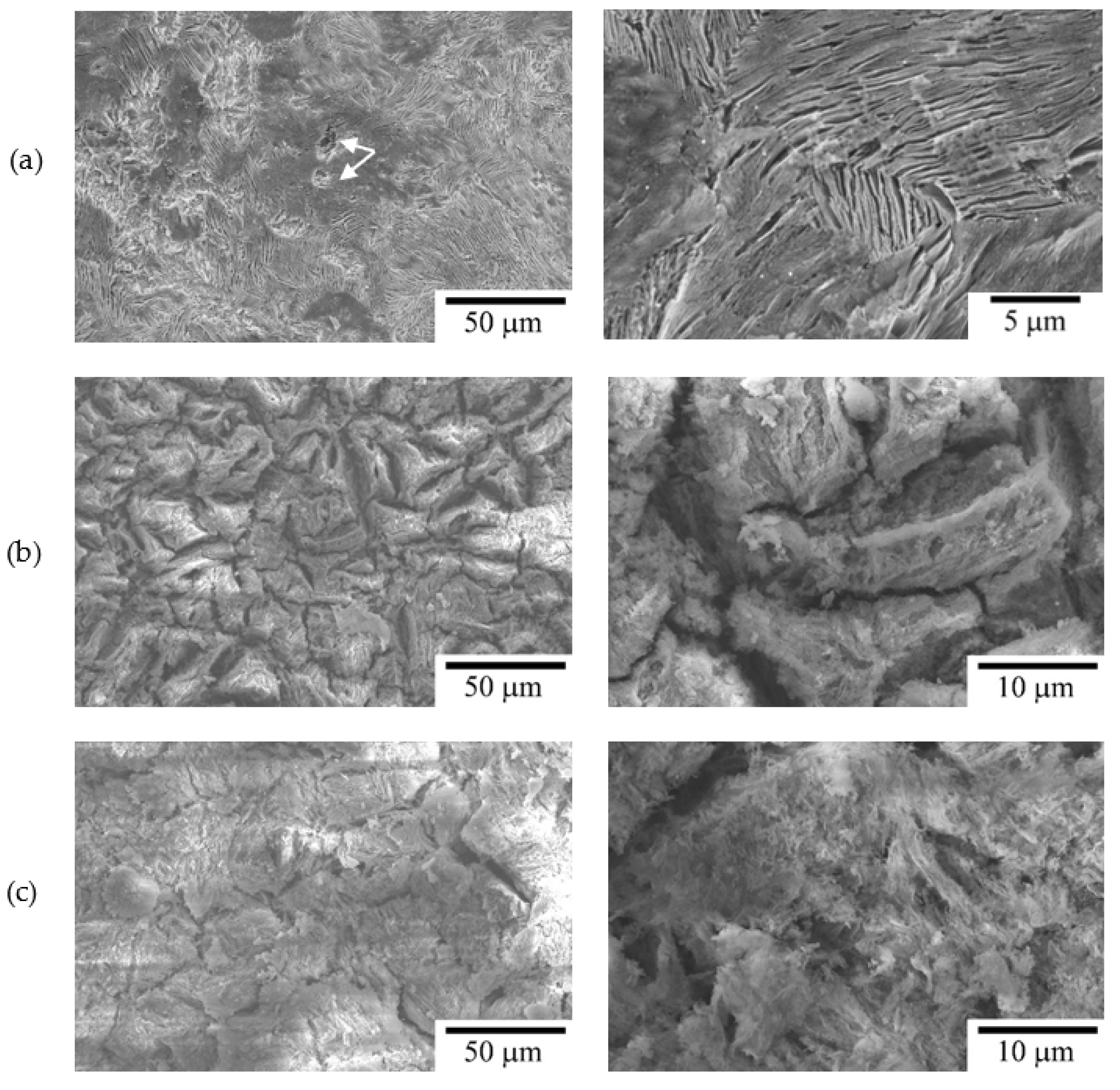
3.1. Microstructural Analysis

Figure 2 shows SEM micrographs of U75V, U20Mn-1, and U20Mn-2 steels. The U75V steel (Figure 2a) reveals most of the pearlitic structure (denoted as P) with a small amount of proeutectoid ferritic phase (denoted as F). The U20Mn-1 steel (Figure 2b) reveals a granular bainitic structure with blocky martensitic/austenitic (M/A) islands. The vast heat is usually generated during the bainitic transformation, i.e., phase transformation with latent heat. Hence, the rail was cooled at an extremely low cooling rate once the bainitic transformation is activated. The untransformed austenite could transform to martensite when the bainitic transformation is discontinued, and the temperature is below the Ms (martensitic transformation start temperature, Ms, ~340 °C). This air-cooling process for U20Mn-1 steel is also similar to the bainitic austempering (BAT) process. Hence, it is suggested that the granular bainitic ferrite phase was possibly formed during the BAT process. In contrast, the U20Mn-2 steel (Figure 2c) shows the multiphase of acicular bainitic ferrite, martensite, and retained austenite, which is usually found in the bainitic quenching and partitioning (BQ&P) process [25,27,28]. The volume fractions of retained austenite in the U20Mn-1 and U20Mn-2 steels are about 5.6 vol.% and 4.9 vol.%, respectively, as measured by XRD [29]. The acicular bainite was possibly formed during the partitioning step at 320 °C. The U20Mn-2 yields a finer bainitic structure than that presented in the U20Mn-1 steels due to the accelerated cooling rate for U20Mn-2. The accelerated cooling could reduce the transformation temperature, which leads to the bainitic transformation at a lower temperature range and subsequent refined bainitic microstructure. It is noted that a few fine carbides were also observed in the acicular bainite in the U20Mn-2 rail steel [29].

3.2. Immersion Test

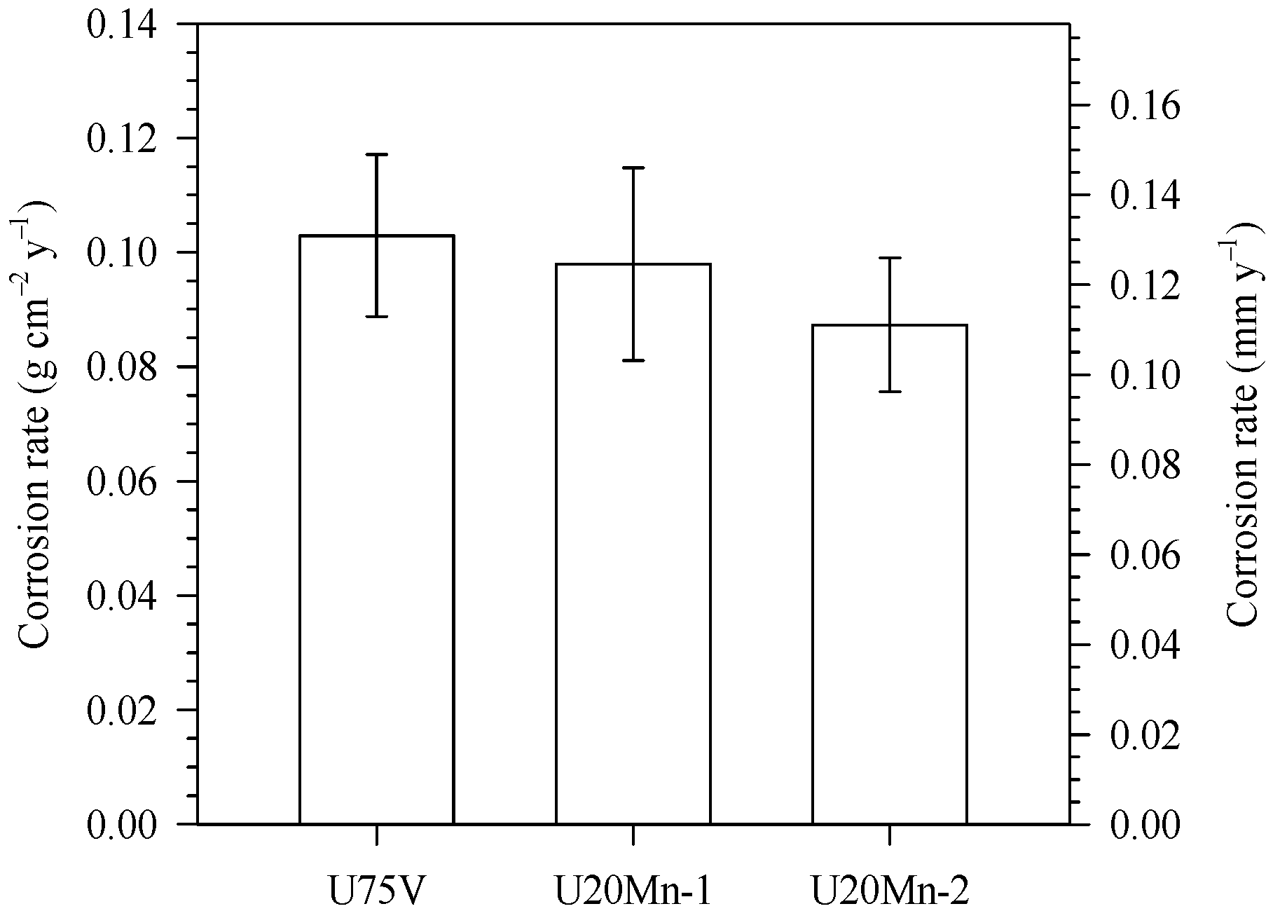
3.2.1. Weight Loss Measurement

The average corrosion rates (g cm−2 y−1) versus immersion time up to four weeks or 28 days of immersion test in freely aerated 3.5 wt.% of NaCl solution is shown in Figure 3 and Table 1. The mass loss was averaged from three immersion samples in the same condition. The corrosion rates of the immersed steels were calculated by using the following equation from ASTM-G1-03:
Corrosion   rate   ( g   cm 2 y 1 ) = 0.365   Δ w t .
where ∆w is the mass loss per area (mg cm−2) and t is the time for immersion test (day).
For all samples, the average mass loss increased with increasing immersion times. After one week of immersion, the U75V steel showed a slightly higher corrosion rate compared to that of the U20Mn-1 and U20Mn-2 steels. With increasing immersion times, the average corrosion rates of all steels decreased. The U20Mn-1 and U20Mn-2 steels exhibited similar average corrosion rates after four weeks of immersion. The corrosion rate after week four is about 0.1 g cm−2 y−1 for U75V pearlitic steel, whereas it is 0.087 g cm−2 y−1 for U20Mn-1 and U20Mn-2 bainitic rail steels. The corrosion rate is reduced by ~13%. To conclude, the corrosion rate calculated from the immersion test of U75V was higher than the other two steels, i.e., the U20Mn-1 and U20Mn-2 steels.

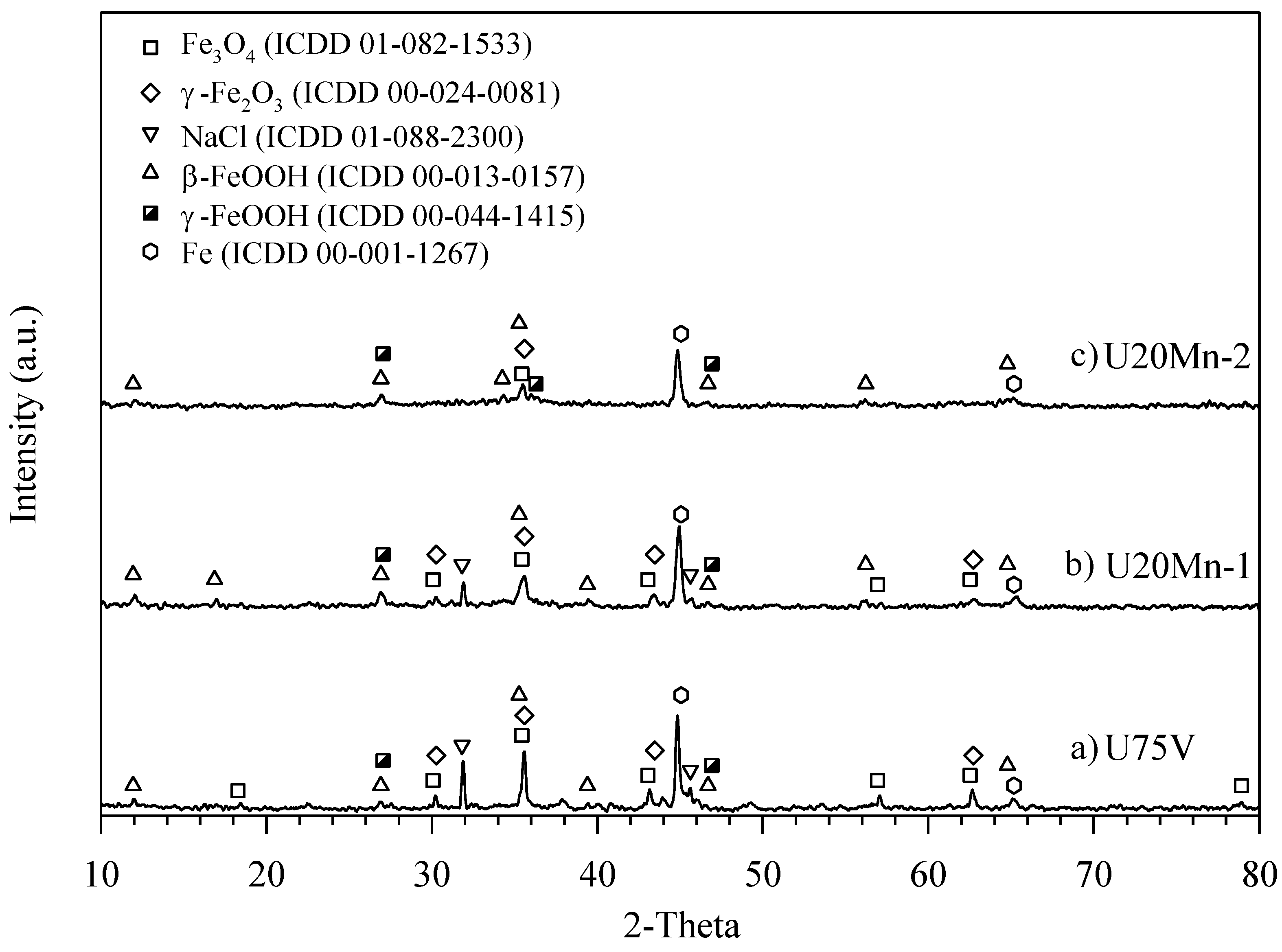
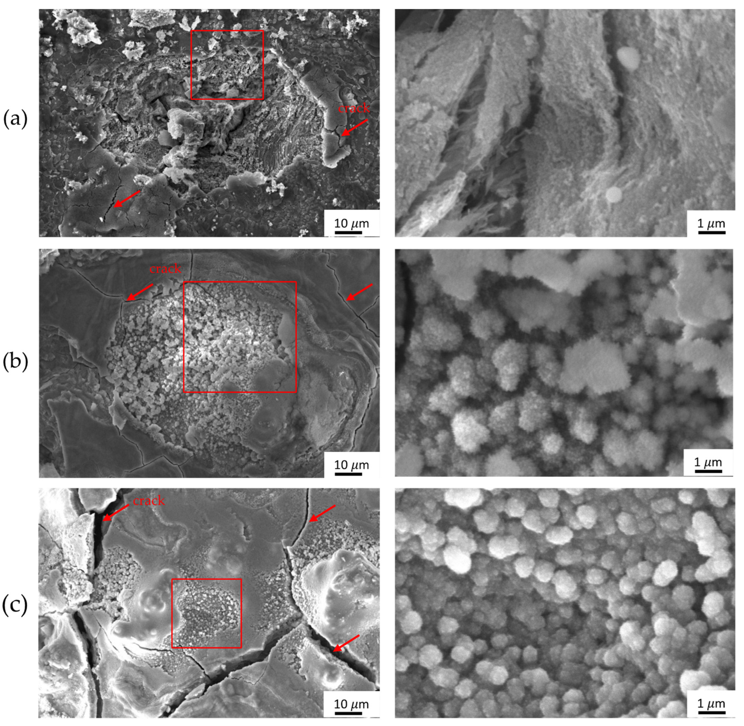
3.2.2. Rust Microstructure

Fourier transform infrared spectra obtained after the immersion test is shown in Figure 4. Absorption peaks at higher wavelengths from ~3315 cm−1 to ~3371 cm−1 and absorption peaks around ~1605 cm−1 appeared due to O-H stretching of H2O molecule bands in all samples [30,31,32]. The presence of γ-FeOOH was found at peaks ~1151 cm−1 and ~1025 cm−1. A peak at ~823 cm−1 corresponds to α-FeOOH. The absorption bands between 650 to 450 cm−1 suggest the exhibit of Fe–O stretching vibration of Fe2O3. Magnetite phase is found at peak ~570 cm−1 where Fe-O stretching at tetrahedral and octahedral sites [33]. Further, the Fe-O vibration band of maghemite (γ-Fe2O3), a defective form of magnetite, has absorption bands at ~630 cm−1.
Furthermore, XRD (Figure 5) was conducted to confirm phases in rust after the immersion test. Hydroxide phases, such as γ-FeOOH, along with major oxide phases, such as Fe3O4 and γ-Fe2O3, were found both in XRD and FTIR. In addition, β-FeOOH and NaCl peaks were also shown in XRD spectra. β-FeOOH is favored under the chloride environment and it was reported that β-FeOOH prefers to form under the NaCl structure because the chloride ion of the NaCl phase stabilizes the existence of β-FeOOH [34]. However, the β-FeOOH peaks at 860 cm−1 and 670 cm−1 were not found in FTIR spectra due to broadening peaks of α-FeOOH (823 cm−1) and γ-Fe2O3 (~630 cm−1), at the same range of adsorption wavelength, respectively.
Corroded steels collected after three weeks of immersion were examined by SEM and are shown in Figure 6. Low magnification of SEM micrographs presents morphology of rust on U75V, U20Mn-1, and U20Mn-2 steels. A compact layer of oxide was found across the entire surface in all steels, and it was identified as Fe3-xO4 [9,32,35]. Cracks, as marked by red arrows, have appeared on the Fe3-xO4 layer. Corrosion of all steels occurred localized, which allows the presence of craters on the surface. No evidence of pits was found in all steels. Craters were decorated with oxide and hydroxide corrosion products, shown in squares. The U20Mn-2 steel (Figure 6c) exhibits shallow and smaller size of craters. Also, deeper craters were noticed in the U75V steel (Figure 6a) compared with the ones shown in U20Mn-1 (Figure 6b) and U20Mn-2 (Figure 6c) steels. Higher magnification of SEM micrographs captured a cotton ball-like structure of corrosion products in craters in all steels.

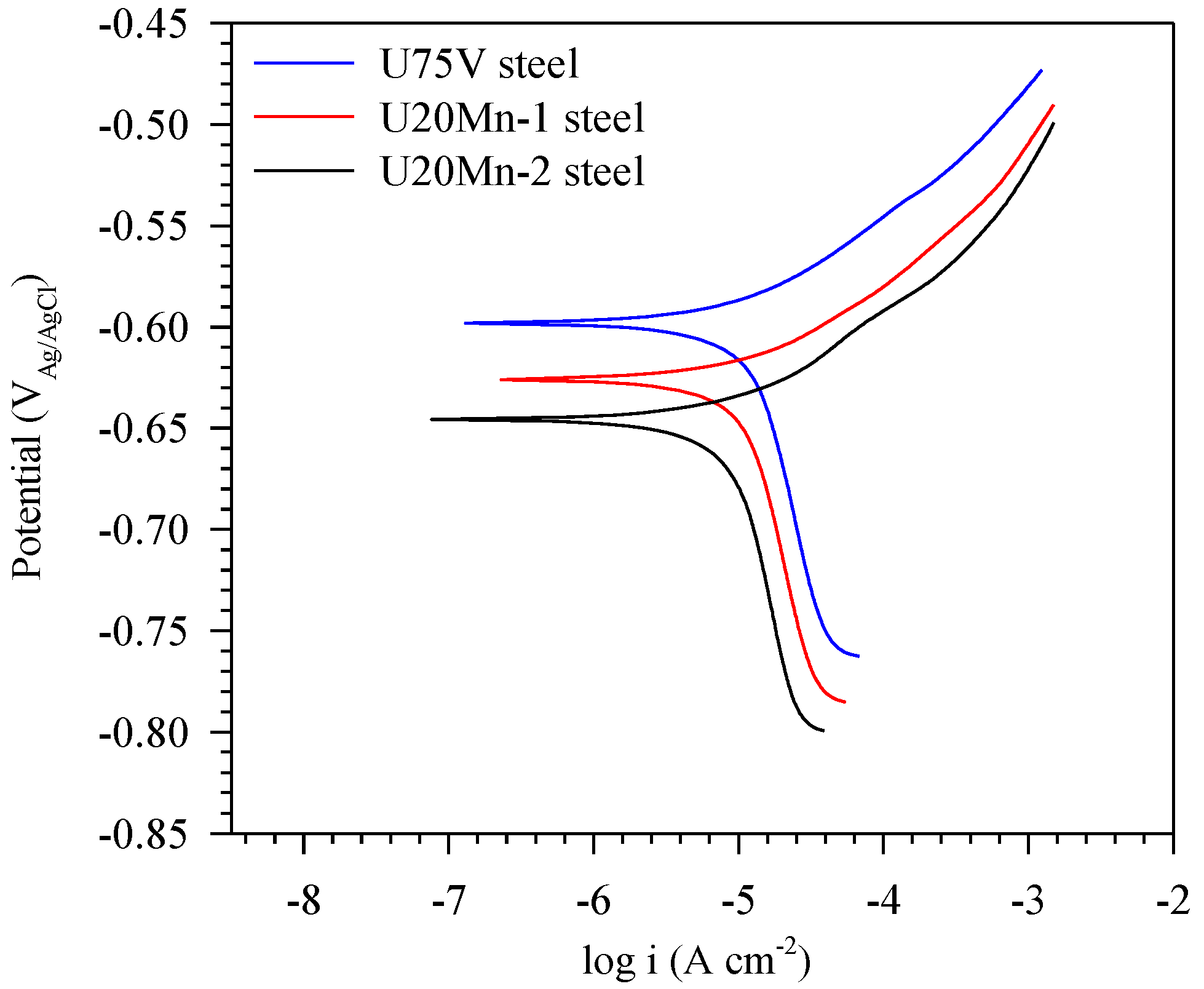
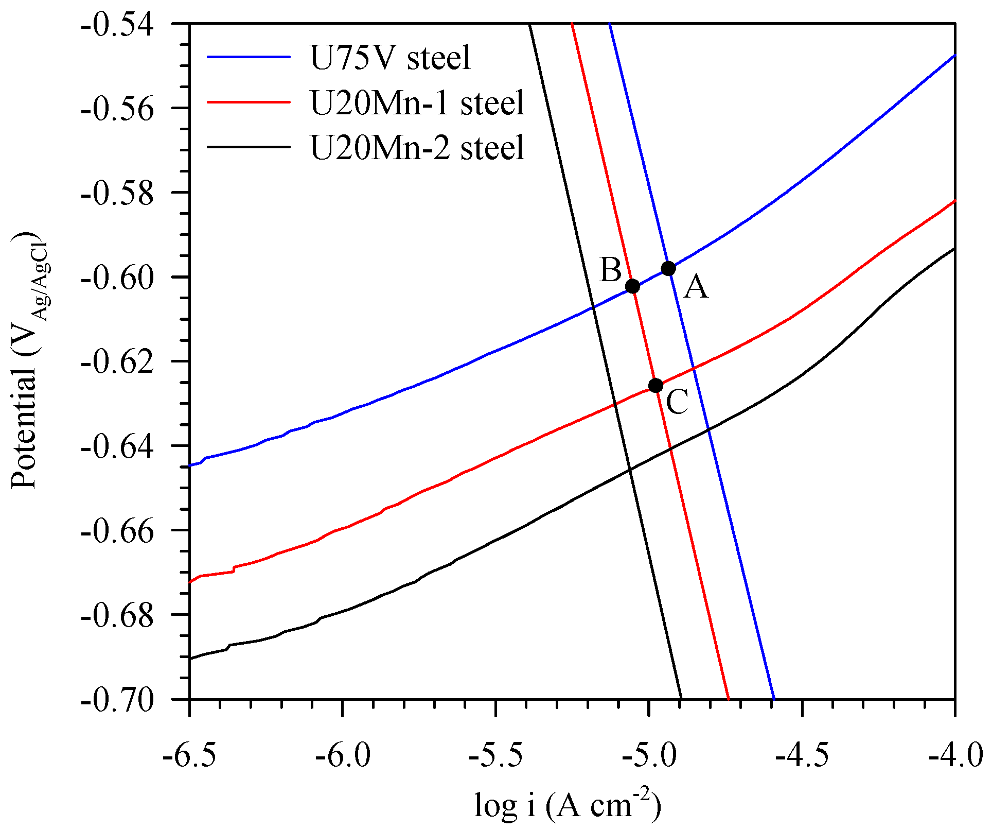
3.3. Electrochemical Test

Figure 7 shows polarization curves of the U75V, U20Mn-1, and U20Mn-2 steels after the electrochemical test in freely aerated 3.5% NaCl solution. Various electrochemical parameters of all steels, such as corrosion potential (Ecorr, V), corrosion current density (icorr, µA cm−2), corrosion rate (g cm−2 y−1), and thickness loss (mm y−1), were calculated from Figure 7 and are listed in Table 2. The corrosion rates of all samples were calculated by using the following equation ASTM G102-89:
Corrosion   rate   ( g   cm 2 y 1 ) = 3.15 × 10 7   i corr × EW F .
Corrosion   rate   ( mm   y 1 ) = 3.15 × 10 8   i corr × EW ρ × F .
where icorr is the corrosion current density (A cm−2), EW is the equivalent weight of iron (27.92 g mol−1), ρ is the density of the steels (7.87 g cm−3), and F is Faraday’s constant.
The corrosion potential of U75V steel is higher than those in U20Mn-1 and U20Mn-2 steels. Ecorr was shifted to a more negative value from U75V, U20Mn-1, and U20Mn-2 steel, respectively. The corrosion current density (icorr) was reduced from 11.28 μA cm−2 in U75V steel to 10.73 μA cm−2 in U20Mn-1 steel to 9.6 μA cm−2 in U20Mn-2 steel. Corrosion rate and thickness loss for the U75V steel were found to be the highest, followed by U20Mn-1 and U20Mn-2 steels (Figure 8). The calculated corrosion rates obtained by PD tests agreed with that from the immersion tests.
Figure 9 shows SEM micrographs of U75, U20Mn-1, and U20Mn-2 steels after electrochemical tests. Characteristic features were visible after electrochemical tests and comparable to the etched SEM micrographs (Figure 2). The pearlitic structure in the U75V steel showed an alternate arrangement of ferrite and cementite where the ferrite phase was dissolution. Pitting was clearly observed in the U75V (denoted as an arrow). However, the multiphase bainite/martensite structure in U20Mn-1 and U20Mn-2 acted differently from the pearlitic U75V steel. The bainitic/martensitic structure of U20Mn-1 and U20Mn-2 steels showed uniform corrosion attacks with rotten-like features.

4. Discussion

Commercially used U75V exhibited most of the pearlitic structure with a small amount of proeutectoid ferritic phase. The bainitic austempering (BAT) and bainitic quenching and partitioning (BQ&P) processes introduced the multiphase bainite + martensite + retained austenite structure, which yields an excellent combination of strength and ductility [25,36]. U20Mn-1 steel, which was subjected to bainitic austempering (BAT), revealed a granular bainitic structure with blocky martensitic/austenitic (M/A) islands, whereas the U20Mn-2 steels, which were subjected to the BQ&P process, showed acicular bainitic ferrite, martensite, and retained austenite structure.
Electrochemical tests in freely aerated 3.5 wt.% solution were conducted for investigation of corrosion behavior. The absence of passive zones in the Tafel plot in all steels (Figure 7) supports an active polarization behavior of steels [37,38]. After the electrochemical test, the pearlitic structure in the U75V steel showed an alternate arrangement of ferrite and cementite where the ferrite phase was dissolution due to a galvanic couple between ferrite and cementite lamellae (Figure 9). The ferrite lamella, which is adjacent to the cementite, acts as a strong anode with respect to the cathodic cementite and produces a formation of galvanic cell within the pearlite structure, resulting in an intense dissolution of the ferritic phase adjacent to cementite [13]. However, the bainitic/martensitic structure of U20Mn-1 and U20Mn-2 steels showed a uniform corrosion attack with the rotten-like feature. A deeply grooved appearance after polarization corresponded to the dissolution of bainitic ferrite, which showed more active than martensite/austenite (M/A) island [9]. The corrosion rate obtained from electrochemical tests showed a similar trend, where U75V had the highest corrosion rate, whereas the U20Mn-1 and U20Mn-2 exhibited similar corrosion resistance, respectively.
To understand the corrosion mechanism, the corrosion behavior of pearlitic steel and multiphase steels were presented in Tafel lines. From Figure 10, the linear relationship between E and log i can be observed in the cathodic range, i.e., in the voltage below −0.60 V for U75 steel. Because in this zone the magnitude of the cathodic current density (ic) is drastically higher than that of the anodic one (ia), the experimentally obtained total current density then coincides with the cathodic current density. The observed straight line is therefore a cathodic linear, or Tafel, line. The linear relationship between E and log ic indicates that the corrosion kinetics is controlled by the transfer reaction at a metal/solution interface obeying the following relationship [37]:
E = 2.3 β c log i c + β c ln ( nFk c c ox ) .
Equations describing the cathodic lines of the studied samples can be extracted from Figure 7 and replotted in Figure 10. When changing the steel from pearlitic U75V to the multiphase U20Mn steels, the cathodic line shifts to a more negative direction, indicating that the value of the y-intercept of the E-log ic plot, β c ln ( nFk c c ox ) , is less. In the NaCl aqueous solution, the cathodic reaction is reported to be O2 + 2H2O + 4e = 4OH with oxygen as an oxidizer [10]. The reduction of the term β c ln ( nFk c c ox ) includes that the concentration of the oxidizer, the dissolved oxygen, is reduced. Uhlig and Revie [39] suggested that the reduction in the concentration of the dissolved oxygen could be from the decrease in surface area of the cathodic cementite phase, which is possible because of the decreased carbon content in the multiphase steel. Since the U20Mn steel has lower carbon content than that of the U75 steel, it is possible that the shift of the cathodic line of U20Mn steel to a more negative direction may be due to the reduced carbon content of this steel.
In addition, once the cathodic line is determined, the anodic line can also be found out by the relation, ia = i − ic, as suggested by Jones [40]. The anodic lines, extracted from the polarization curves in Figure 7, are replotted in Figure 10. Theoretically, these lines should also be linear, obeying the Tafel relation for the anodic reaction [37], but practically, they deviate from linearity, as observed in Figure 10, potentially because of the disturbance at the metal/solution interface by the corrosion reaction in the anodic regime [40].
The shifts in both the cathodic and anodic lines can affect the corrosion current density as it is the current density when the total anodic current density equals the total cathodic one. Graphically, the corrosion current density is an abscissa value of the intersection point between the anodic and cathodic lines in the E- log ic diagram.
By comparing the U75 and U20Mn-1 steels, it can be seen from Figure 10 that if the anodic line is primarily assumed to be unchanged but the cathodic line shifts to the less noble direction, the corrosion current density will move to the lower value, i.e., from the values corresponding to abscissas of points A to B. However, in reality, it is not only the cathodic line that moves due to the change of the steel grade’s composition but also the anodic one. Because of the non-linearity of the anodic line experimentally obtained, the analysis of this shift by a Tafel relationship is therefore limited. However, we can still observe that the anodic line, which also moves to a less noble direction. This move helps increase the corrosion current density to a higher value, i.e., from the values corresponding to abscissas of points B to C. However, this effect is less important than the cathodic shift that reduces the corrosion current density from the ones corresponding to points A to B. Thus, the total effects of these two shifts result in the lowering of the corrosion current density from the ones corresponding to points A to C, as experimentally observed. This explanation can also be used to explain the reduced corrosion current density of the U20Mn-1 steel than that of the U75 one.
When compared between U20Mn-1 and U20Mn-2 steels, the corrosion current density of the latter steel is slightly lower. We clearly observed in Figure 10 that the negative shift of the cathodic line of the U20Mn-2 steel indicates that the U20Mn-2 steel allows more oxygen to be concentrated at the metal/solution interface, thus fostering the cathode reaction. Its surface might also change the cathodic rate constant, kc, to a higher value. However, more experiments are needed to confirm such a hypothesis and merit consideration in future work.
Corrosion behavior and oxide growth of pearlitic and bainitic steels are discussed. The pearlite structure consists of alternate ferrite and cementite lamellae. In a corrosive environment, ferrite acts as an anode, resulting in Fe = Fe2+ + 2e in the oxidation reaction, and cementite acts as a cathode, and the cathodic reaction is O2 + 2H2O + 4e = 4OH. Corrosion takes place and produces a formation of galvanic cells within the pearlite structure, resulting in an intense dissolution of the ferritic phase and leaving cementite unattached [13]. This phenomenon results in the local deep channels of ferrite (Figure 9a). At the same time, oxidation takes place competitively along with corrosion. Progressive dissolution of ferrite and continuous growth of the oxide layer on local deep channels of ferrite and unattached cementite is shown in Figure 6a, in agreement with previous studies by Cabrera-Sierra et al. [41] and Moon et al. [9]. A mixture of oxide and hydroxide phases forms on the steel’s surface. Three hydroxide structures, γ-FeOOH, α-FeOOH, and β-FeOOH, and two oxide phases (γ-Fe2O3, and Fe3O4) were found on the pearlitic steel. The SEM micrograph (Figure 6a) captured a large number of cotton ball-like structures, which are the α-FeOOH, growing on top of the Fe3-xO4 compact oxide layer [9,42]. It is noticed that the rust of U75V steels exhibited cleavage along with the cotton ball structure of α-FeOOH. During immersion, the γ-FeOOH first forms and later dissolves when increasing immersion times. The γ-FeOOH later precipitates to form amorphous ferric hydroxide α-FeOOH [43], which can be found in FTIR spectra (Figure 4) but cannot be detected in XRD spectra due to its amorphous structure (Figure 5). The α-FeOOH is a stable phase due to the high stability of bonding configuration [9,44]. This hydroxide phase is an insulator and has excellent corrosion resistance, which acts as a natural protective layer of the steel substrate. Additionally, a thick compact layer of Fe3-xO4 under the rust layer was formed. The Fe3-xO4 structure is non-stoichiometric, which consists of Fe2+ and Fe3+ ions. The value of x ranges from 0 to 1/3. When x equals 1/3, the structure of Fe3-xO4 has maximum stoichiometry and corresponds to the γ-Fe2O3 (maghemite) phase. [25,26] are found in both FTIR (Figure 4) and XRD (Figure 5) spectra. This thick and compact layer of Fe3-xO4 effectively hinders the corrosion reaction yielding to the lower corrosion rate after its formation.
The aforementioned oxide and hydroxide phases that are found in the pearlitic steel are also found in the rust of bainitic steels. The oxide and hydroxide growth formation during a corrosion attack is similar. However, the corrosion behaviors of these multi-phase bainitic steels are different. The multiphase bainitic steels consist of aggregates of sheaves of bainitic ferrite along with martensite lath and retained austenite (Figure 2). Fine cementites were also observed in the acicular bainite in the U20Mn-2 rail steel [29]. These fine cementites, which are uniformly distributed and discretely, act as cathodes, and bainitic ferrites act as anodes. In the early stage of corrosion, the governing mechanism of bainitic steels is similar to pearlitic steel. However, a large number of fine cathodic cementites along with a large area of anodic bainitic ferrite cause less severity of dissolution of anodic bainitic ferrite. This results in the shallower and smaller size of craters (Figure 6b,c) and a lower corrosion rate (Table 2 and Figure 8), compared to pearlitic steel. Simultaneously, oxide and hydroxide rusts form uniformly on the bainitic steels, resulting in better corrosion resistance. Trends of corrosion rate obtained from the PD test and immersion test are similar, i.e., U75V > U20Mn-1 > U20Mn-2. From these results, BAT and BQ&P heat treatments resulting in multiphase bainite + martensite + retained austenite microstructure play a crucial role in the corrosion behavior of modern high-speed rail steels.

5. Conclusions

The present study investigated the corrosion behavior of pearlitic and multi-phase bainitic/martensitic steels, and the following conclusions were obtained:
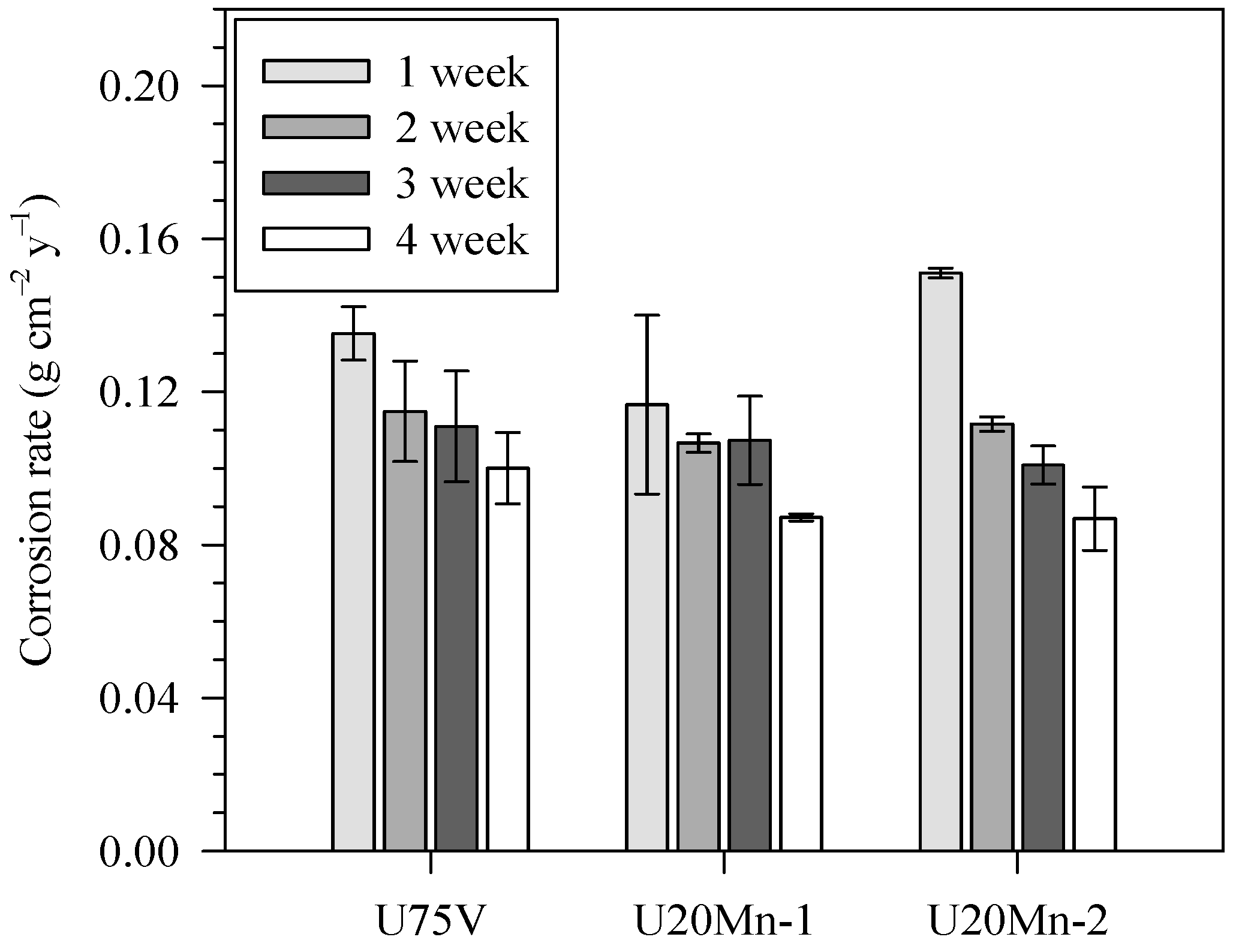
  • Multi-phase bainitic/martensitic steels showed slightly higher corrosion resistance than commercially pearlitic steel. The corrosion rate after week four of the immersion test is about 0.1 g cm−2 y−1 for U75V pearlitic steel, whereas it is 0.087 g cm−2 y−1 for U20Mn-1 and U20Mn-2 bainitic rail steels. The corrosion rate is reduced by ~13%. The electrochemical analysis also agreed with the tendency.
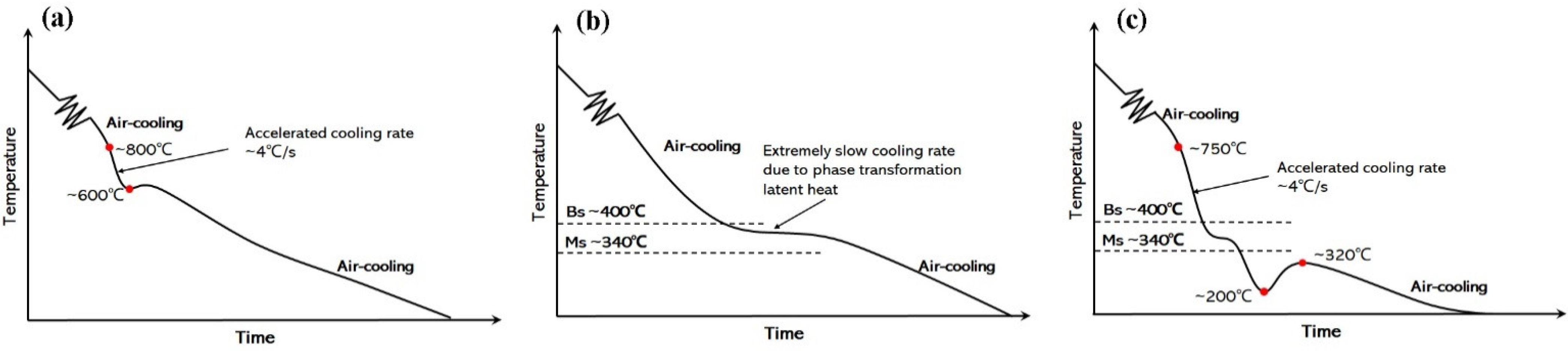
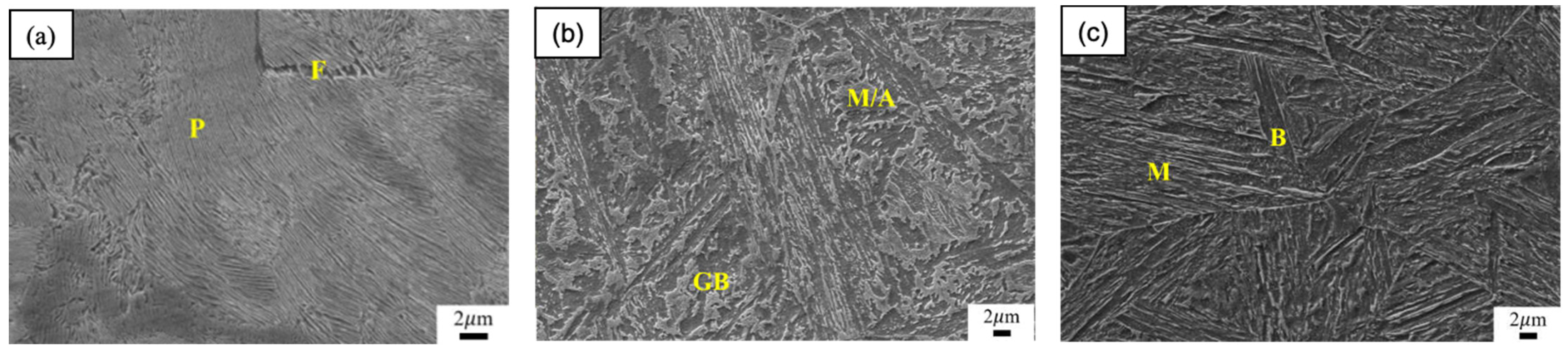
  • In the case of the same elemental composition, a combination of acicular bainitic ferrite, martensite, and retained austenite, which was obtained from the bainitic quenching and partitioning (BQ&P) process, showed slightly higher corrosion resistance compared to the granular bainitic ferrite + martensite/austenite structure obtained from the bainitic austempering (BAT) process.
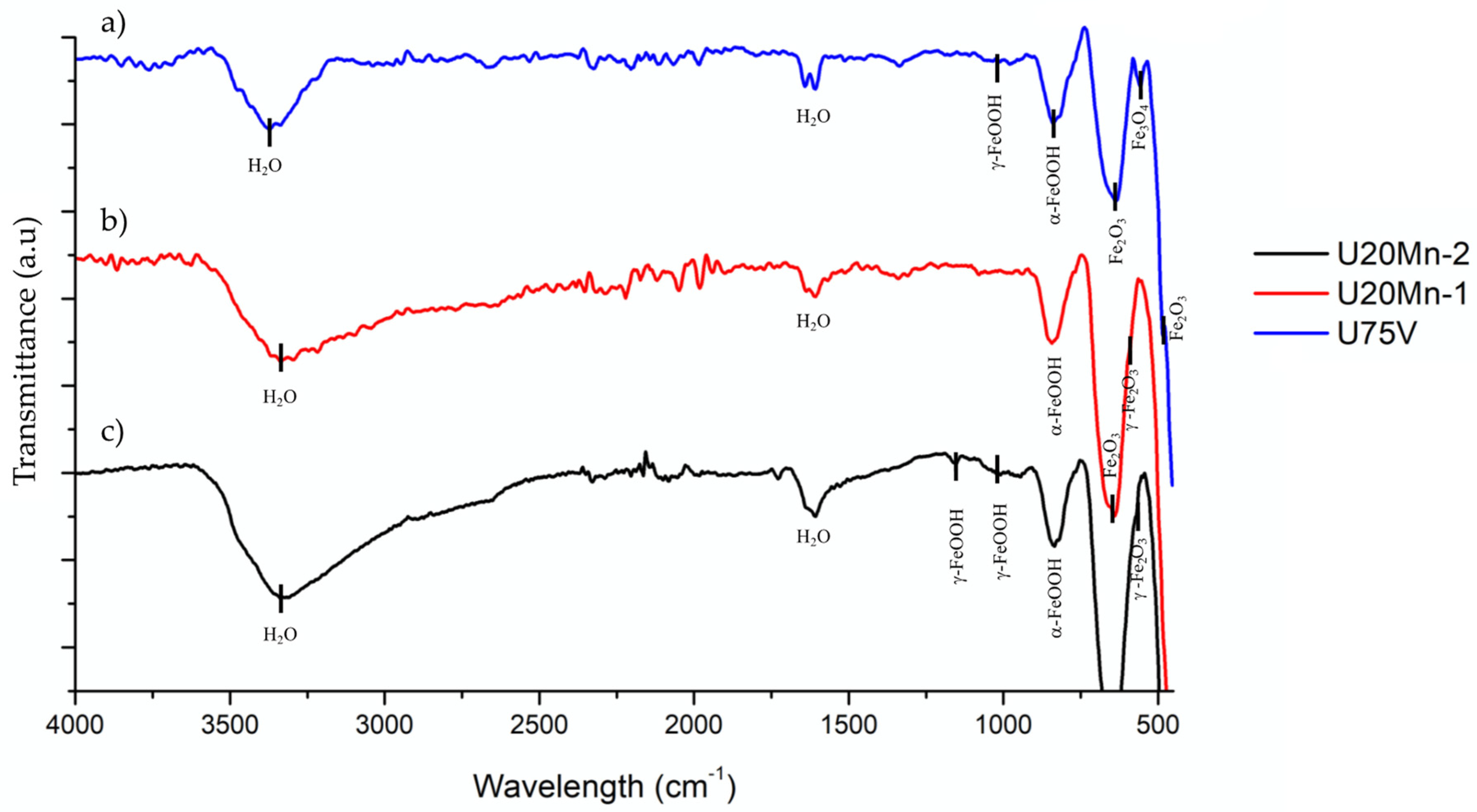
  • Fourier transform infrared spectra and X-ray diffraction results indicated that rust after immersion test consisted of three hydroxide structures, γ-FeOOH, β-FeOOH, and α-FeOOH, and 2 oxide phases (γ-Fe2O3, and Fe3O4). The corroded surface showed that the deeper craters were noticed in the U75V steel compared to the bainitic rail steels.

Author Contributions

T.R.: methodology, investigation, formal analysis, writing—original draft preparation, funding acquisition; T.T.: methodology, investigation, writing—original draft preparation; M.H.S.B.: methodology, investigation, writing—original draft preparation; S.C.-a.: formal analysis, writing—original draft preparation, supervision; G.G.: writing—review and editing, supervision; Z.Y.: writing—review and editing, supervision. All authors have read and agreed to the published version of the manuscript.

Funding

This research was funded by Thailand Science Research and Innovation Fund, King Mongkut’s University of Technology North Bangkok (Contract No. KMUTNB-MHESI-64-02), and King Mongkut’s University of Technology North Bangkok, Thailand (Contract No. KMUTNB-post-64-04).

Institutional Review Board Statement

Not applicable.

Informed Consent Statement

Not applicable.

Data Availability Statement

The data presented in this study are available upon request from the corresponding author.

Conflicts of Interest

The authors declare no conflict of interest.

References

  1. Al-Hamed, K.; Dincer, I. A novel integrated solid-oxide fuel cell powering system for clean rail applications. Energy Convers. Manag. 2020, 205, 112327. [Google Scholar] [CrossRef]
  2. Olivares, R.O.; Garcia, C.; DeArdo, A.; Kalay, S.; Hernández, F.R. Advanced metallurgical alloy design and thermomechanical processing for rails steels for North American heavy haul use. Wear 2011, 271, 364–373. [Google Scholar] [CrossRef]
  3. Aglan, H.; Liu, Z.; Hassan, M.; Fateh, M. Mechanical and fracture behavior of bainitic rail steel. J. Mater. Process. Technol. 2004, 151, 268–274. [Google Scholar] [CrossRef]
  4. Chen, H.; Zhang, C.; Liu, W.; Li, Q.; Chen, H.; Yang, Z.; Weng, Y. Microstructure evolution of a hypereutectoid pearlite steel under rolling-sliding contact loading. Mater. Sci. Eng. A 2016, 655, 50–59. [Google Scholar] [CrossRef]
  5. Bhadeshia, H.K.D.H. Bainite in Steels: Transformation, Microstructure and Properties; IOM: London, UK, 2001; pp. 237–276. [Google Scholar]
  6. Hasan, S.M.; Ghosh, M.; Chakrabarti, D.; Singh, S.B. Development of continuously cooled low-carbon, low-alloy, high strength carbide-free bainitic rail steels. Mater. Sci. Eng. A 2020, 771, 138590. [Google Scholar] [CrossRef]
  7. Neog, S.P.; Bakshi, S.D.; Das, S. Effect of normal loading on microstructural evolution and sliding wear behaviour of novel continuously cooled carbide free bainitic steel. Tribol. Int. 2021, 157, 106846. [Google Scholar] [CrossRef]
  8. Xu, W.; Zhang, B.; Deng, Y.; Wang, Z.; Jiang, Q.; Yang, L.; Zhang, J. Corrosion of rail tracks and their protection. Corr. Rev. 2021, 39, 1–13. [Google Scholar] [CrossRef]
  9. Moon, A.; Sangal, S.; Layek, S.; Giribaskar, S.; Mondal, K. Corrosion behavior of high-strength bainitic rail steels. Metall. Mater. Trans. A 2015, 46, 1500–1518. [Google Scholar] [CrossRef]
  10. Katiyar, P.K.; Misra, S.; Mondal, K. Comparative corrosion behavior of five microstructures (pearlite, bainite, spheroidized, martensite, and tempered martensite) made from a high carbon steel. Metall. Mater. Trans. A 2019, 50, 1489–1501. [Google Scholar] [CrossRef]
  11. Katiyar, P.K.; Misra, S.; Mondal, K. Corrosion behavior of annealed steels with different carbon contents (0.002, 0.17, 0.43 and 0.7% C) in freely aerated 3.5% NaCl solution. J. Mater. Eng. Perform. 2019, 28, 4041–4052. [Google Scholar] [CrossRef]
  12. Moon, A.; Chandra Sekhar, K.; Mahanty, S.; Sangal, S.; Mondal, K. Corrosion behavior of newly developed high-strength bainitic railway wheel steels. J. Mater. Eng. Perform. 2020, 29, 3443–3459. [Google Scholar] [CrossRef]
  13. Katiyar, P.K.; Sangal, S.; Mondal, K. Effect of various phase fraction of bainite, intercritical ferrite, retained austenite and pearlite on the corrosion behavior of multiphase steels. Corros. Sci. 2021, 178, 109043. [Google Scholar]
  14. Mohd Fauzi, M.A.; Saud, S.N.; Hamzah, E.; Mamat, M.F.; Ming, L.J. In vitro microstructure, mechanical properties and corrosion behaviour of low, medium and high carbon steel under different heat treatments. J. Bio-Tribo-Corros. 2019, 5, 37. [Google Scholar] [CrossRef]
  15. Gao, G.; Gao, B.; Gui, X.; Hu, J.; He, J.; Tan, Z.; Bai, B. Correlation between microstructure and yield strength of as-quenched and Q&P steels with different carbon content (0.06–0.42 wt% C). Mater. Sci. Eng. A 2019, 753, 1–10. [Google Scholar]
  16. Gui, X.; Wang, K.; Gao, G.; Misra, R.; Tan, Z.; Bai, B. Rolling contact fatigue of bainitic rail steels: The significance of microstructure. Mater. Sci. Eng. A 2016, 657, 82–85. [Google Scholar] [CrossRef]
  17. Guo, J.; Yang, S.; Shang, C.; Wang, Y.; He, X. Influence of carbon content and microstructure on corrosion behaviour of low alloy steels in a Cl− containing environment. Corros. Sci. 2009, 51, 242–251. [Google Scholar] [CrossRef]
  18. Lu, S.; Yao, K.; Chen, Y.; Wang, M.; Chen, N.; Ge, X. Effect of quenching and partitioning on the microstructure evolution and electrochemical properties of a martensitic stainless steel. Corros. Sci. 2016, 103, 95–104. [Google Scholar] [CrossRef]
  19. Singh, K.; Singh, A. Comparative electrochemical impedance spectroscopy study in chloride environment of nano-structured bainitic steels prepared by austempering at varied temperatures. Eng. Res. Express 2020, 2, 035040. [Google Scholar] [CrossRef]
  20. Wei, J.; Dong, J.; Zhou, Y.; He, X.; Wang, C.; Ke, W. Influence of the secondary phase on micro galvanic corrosion of low carbon bainitic steel in NaCl solution. Mater. Charact. 2018, 139, 401–410. [Google Scholar] [CrossRef]
  21. Xu, W.; Deng, Y.; Zhang, B.; Zhang, J.; Peng, Z.; Hou, B.; Duan, J. Crevice corrosion of U75V high-speed rail steel with varying crevice gap size by in-situ monitoring. J. Mater. Res. Technol. 2022, 16, 1856–1874. [Google Scholar] [CrossRef]
  22. Yang, J.; Lu, Y.; Guo, Z.; Gu, J.; Gu, C. Corrosion behaviour of a quenched and partitioned medium carbon steel in 3.5 wt.% NaCl solution. Corros. Sci. 2018, 130, 64–75. [Google Scholar] [CrossRef]
  23. Speer, J.; Matlock, D.K.; De Cooman, B.C.; Schroth, J. Carbon partitioning into austenite after martensite transformation. Acta Mater. 2003, 51, 2611–2622. [Google Scholar] [CrossRef]
  24. Inam, A.; Hafeez, M.; Atif, M.; Ishtiaq, M.; Hassan, M.; Hussain, T.; Mughal, M.; Raza, M.; Abbas, M.; Ullah, I. Microstructural, Mechanical, and Electrochemical Properties of Quenched and Partitioned 3 wt% Mn Steel. Arab. J. Sci. Eng. 2021, 46, 417–423. [Google Scholar] [CrossRef]
  25. Gao, G.; Zhang, H.; Gui, X.; Luo, P.; Tan, Z.; Bai, B. Enhanced ductility and toughness in an ultrahigh-strength Mn–Si–Cr–C steel: The great potential of ultrafine filmy retained austenite. Acta Mater. 2014, 76, 425–433. [Google Scholar] [CrossRef]
  26. Inam, A.; Imtiaz, Y.; Hafeez, M.A.; Munir, S.; Ali, Z.; Ishtiaq, M.; Hassan, M.H.; Maqbool, A.; Haider, W. Effect of tempering time on microstructure, mechanical, and electrochemical properties of quenched–partitioned–tempered Advanced High Strength Steel (AHSS). Mater. Res. Express 2019, 6, 126509. [Google Scholar] [CrossRef]
  27. Gao, G.; Zhang, H.; Tan, Z.; Liu, W.; Bai, B. A carbide-free bainite/martensite/austenite triplex steel with enhanced mechanical properties treated by a novel quenching–partitioning–tempering process. Mater. Sci. Eng. A 2013, 559, 165–169. [Google Scholar] [CrossRef]
  28. Gao, G.; Zhang, H.; Gui, X.; Tan, Z.; Bai, B. Tempering behavior of ductile 1700 MPa Mn–Si–Cr–C Steel treated by quenching and partitioning process incorporating bainite formation. J. Mater. Sci. Technol. 2015, 31, 199–204. [Google Scholar] [CrossRef]
  29. Liu, M.; Fan, Y.; Gui, X.; Hu, J.; Wang, X.; Gao, G. Relationship between Microstructure and Properties of 1380 MPa Grade Bainitic Rail Steel Treated by Online Bainite-Based Quenching and Partitioning Concept. Metals 2022, 12, 330. [Google Scholar] [CrossRef]
  30. Stoia, M.; Istratie, R.; Păcurariu, C. Investigation of magnetite nanoparticles stability in air by thermal analysis and FTIR spectroscopy. J. Therm. Anal. Calorim. 2016, 125, 1185–1198. [Google Scholar] [CrossRef]
  31. Balasubramaniam, R.; Kumar, A.R. Characterization of Delhi iron pillar rust by X-ray diffraction, Fourier transform infrared spectroscopy and Mössbauer spectroscopy. Corros. Sci. 2000, 42, 2085–2101. [Google Scholar] [CrossRef]
  32. Panda, B.; Balasubramaniam, R.; Dwivedi, G. On the corrosion behaviour of novel high carbon rail steels in simulated cyclic wet–dry salt fog conditions. Corros. Sci. 2008, 50, 1684–1692. [Google Scholar] [CrossRef]
  33. Ishii, M.; Nakahira, M.; Yamanaka, T. Infrared absorption spectra and cation distributions in (Mn, Fe) 3O4. Solid State Commun. 1972, 11, 209–212. [Google Scholar] [CrossRef]
  34. Yamashita, M.; Misawa, T.; SJ, O.; Balasubramanian, R. Mössbauer spectroscopic study on X-ray amorphous substance in rust layer of weathering steel subjected to long-term exposure in North America. Zairyo-to-Kankyo 2000, 49, 82–87. [Google Scholar] [CrossRef] [Green Version]
  35. Raman, A.; Nasrazadani, S.; Sharma, L. Morphology of rust phases formed on weathering steels in various laboratory corrosion tests. Metallography 1989, 22, 79–96. [Google Scholar] [CrossRef]
  36. Li, J.; Zhu, Z.; Chen, H.; Li, S.; Wu, H.; Gao, X.; Du, L.; Song, L. Corrosion Behavior of Corrosion-Resistant Spring Steel Used in High Speed Railway. Appl. Sci. 2021, 11, 8668. [Google Scholar] [CrossRef]
  37. Bai, B.; Gao, G.; Gui, X.; Tan, Z.; Weng, Y. Enhanced mechanical properties of ultrahigh strength Mn–Si–Cr–C steels treated by a novel bainitic transformation plus quenching and partitioning process. Heat Treat. Surf. Eng. 2019, 1, 63–71. [Google Scholar] [CrossRef]
  38. Landolt, D. Corrosion and Surface Chemistry of Metals; EPFL Press: Lausanne, Switzerland, 2007. [Google Scholar]
  39. Fontana, M.G.; Greene, N.D. Corrosion Engineering; McGraw-Hill: New York, NY, USA, 2018. [Google Scholar]
  40. Uhlig, H.H.; Revie, R.W. Corrosion and Corrosion Control; John Wiley & Sons: Hoboken, NJ, USA, 1985. [Google Scholar]
  41. Jones, D.A. Principles and Prevention of Corrosion; Prentice Hall: Hoboken, NJ, USA, 1996. [Google Scholar]
  42. Cabrera-Sierra, R.; Batina, N.; González, I. Electrochemical characterization of pearlite phase oxidation of 1018 carbon steel in a borate medium using ECSTM technique. J. Electrochem. Soc. 2005, 152, B534. [Google Scholar] [CrossRef]
  43. Ishikawa, T.; Takeuchi, K.; Kandori, K.; Nakayama, T. Transformation of γ-FeOOH to α-FeOOH in acidic solutions containing metal ions. Colloids Surf. Phys. Eng. Asp. 2005, 266, 155–159. [Google Scholar] [CrossRef]
  44. Misawa, T.; Hashimoto, K.; Shimodaira, S. The mechanism of formation of iron oxide and oxyhydroxides in aqueous solutions at room temperature. Corros. Sci. 1974, 14, 131–149. [Google Scholar] [CrossRef]
Figure 1. Schematic diagram of different heat-treatment processes: (a) U75V, (b) U20Mn-1, and (c) U20Mn-2 steels.
Metals 12 00694 g001
Figure 2. SEM micrographs of different microstructures for rail steel: (a) U75V, (b) U20Mn-1, and (c) U20Mn-2 steels (F: proeutectoid ferrite, P: pearlite, B: bainite, and M: martensite).
Metals 12 00694 g002
Figure 3. Corrosion rates of rail steels after immersion tests.
Metals 12 00694 g003
Figure 4. FTIR spectra of rust of (a) U75V, (b) U20Mn-1, and (c) U20Mn-2 steels after immersion test for 21 days.
Metals 12 00694 g004
Figure 5. XRD spectra of rust of (a) U75V, (b) U20Mn-1, and (c) U20Mn-2 steels after immersion test for 21 days.
Metals 12 00694 g005
Figure 6. SEM micrographs of (a) U75V, (b) U20Mn-1, and (c) U20Mn-2 steels after immersion for 21 days.
Metals 12 00694 g006
Figure 7. Polarization curves of U75V, U20Mn-1, and U20Mn-2 steels after electrochemical test in freely aerated 3.5 % NaCl solution.
Metals 12 00694 g007
Figure 8. The corrosion rate of U75V, U20Mn-1, and U20Mn-2 steels after electrochemical test in freely aerated 3.5 %NaCl solution.
Metals 12 00694 g008
Figure 9. SEM micrographs of (a) U75V, (b) U20Mn-1, and (c) U20Mn-2 steels after electrochemical test in freely aerated 3.5 % NaCl solution.
Metals 12 00694 g009
Figure 10. Tafel slope of U75V, U20Mn-1, and U20Mn-2 steels after electrochemical test in freely aerated 3.5 % NaCl solution.
Metals 12 00694 g010
Table 1. Corrosion rates of rail steels after immersion tests.
SteelCorrosion Rate Due to Mass Loss (g cm−2 y−1)
1 Week2 Week3 Week4 Week
U75V0.135 ± 0.0070.115 ± 0.0130.111 ± 0.0140.100 ± 0.009
U20Mn-10.117 ± 0.0230.107 ± 0.0020.107 ± 0.0120.087 ± 0.001
U20Mn-20.151 ± 0.0010.112 ± 0.0020.101 ± 0.0050.087 ± 0.008
Table 2. Various electrochemical parameters of U75V, U20Mn-1, and U20Mn-2 steels after electrochemical test in freely aerated 3.5 %NaCl solution.
SteelEcorr (V)icorr (μA cm−2)Corrosion Rate
(g cm−2 y−1)
Thickness Loss
(mm y−1)
U75V−0.620 ± 0.01311.279 ± 1.5510.103 ± 0.0140.131 ± 0.018
U20Mn-1−0.623 ± 0.00310.732 ± 1.8470.098 ± 0.0170.124 ± 0.021
U20Mn-2−0.638 ± 0.0119.570 ± 1.2840.087 ± 0.0120.111 ± 0.015
Publisher’s Note: MDPI stays neutral with regard to jurisdictional claims in published maps and institutional affiliations.

