
Laser Preheating for Hot Crack Reduction in Direct Metal Deposition of Inconel 738LC

Abstract
:1. Introduction
2. Materials and Methods
3. Results and Discussion
4. Conclusions
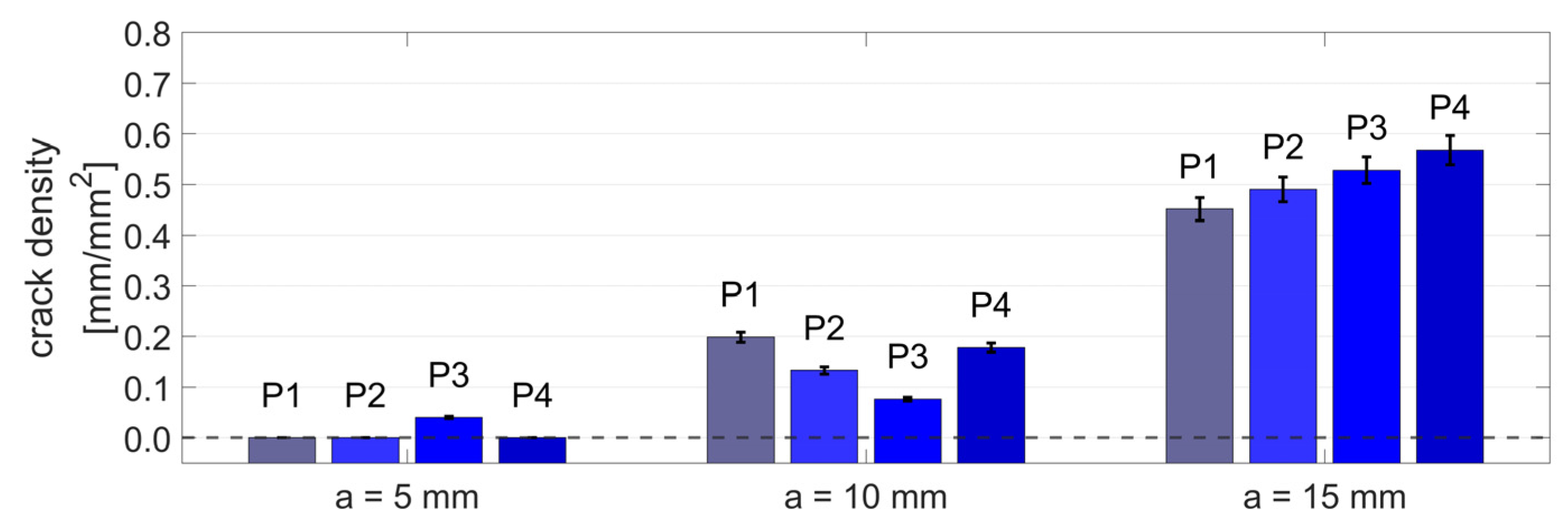
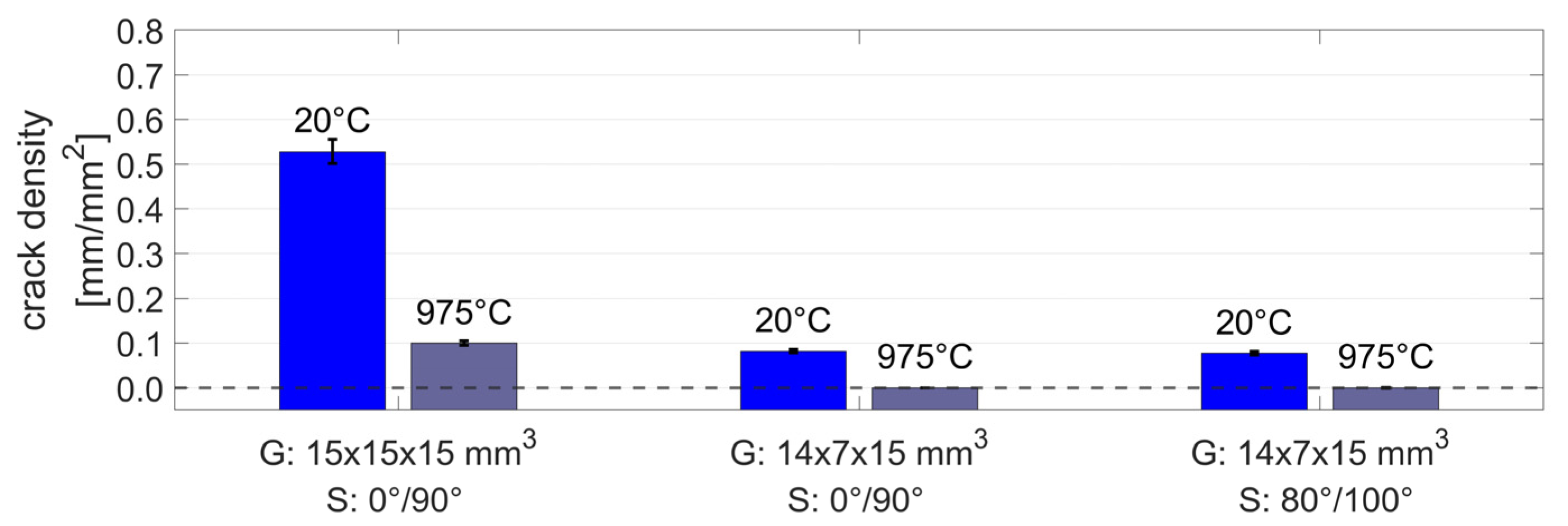
- The crack formation significantly depends on the size of the deposited structure and the solidification conditions because smaller structures heat up and experience low levels of thermal stress. While the smallest cubes with 5 mm edge length were nearly free of cracks, the crack density increased from between 0.08 and 0.20 mm/mm2 to between 0.45 and 0.57 mm/mm2 for the edge lengths 10 mm and 15 mm, respectively.
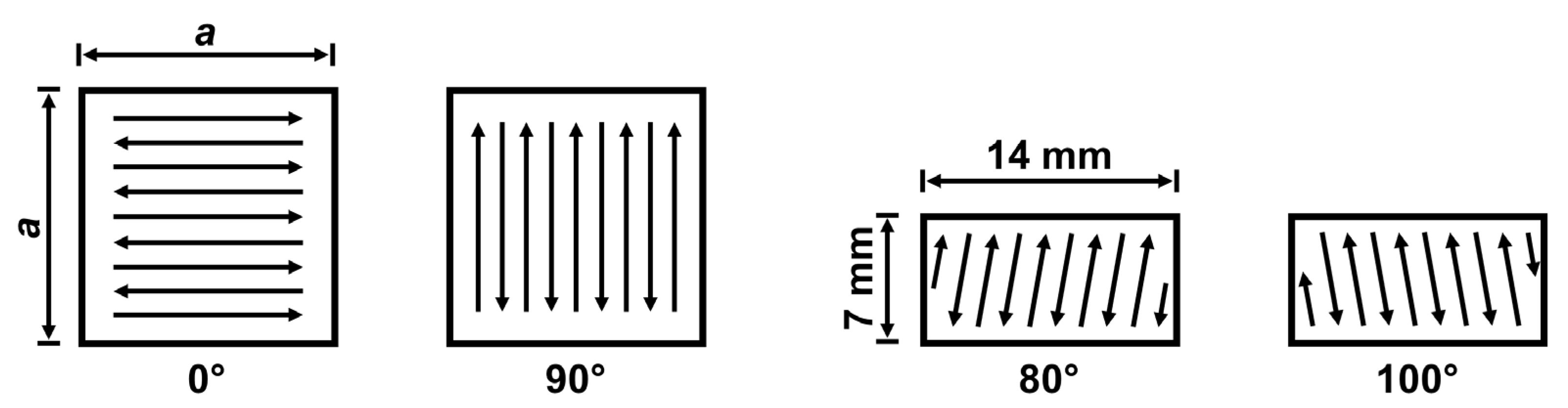
- The variation of scanning speed, powder flow rate, and scanning pattern did not significantly affect the crack formation within the analyzed conditions of this study.
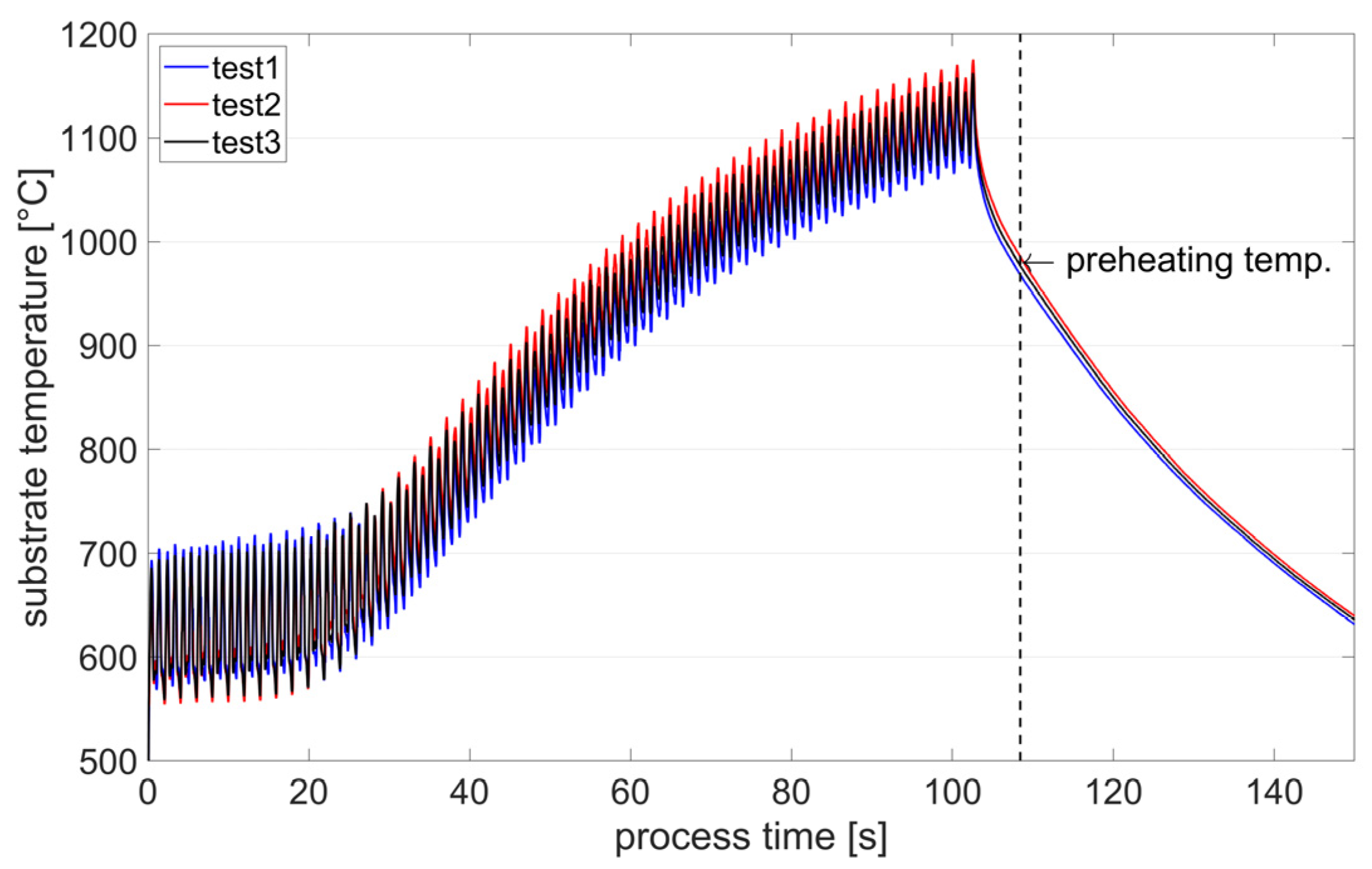
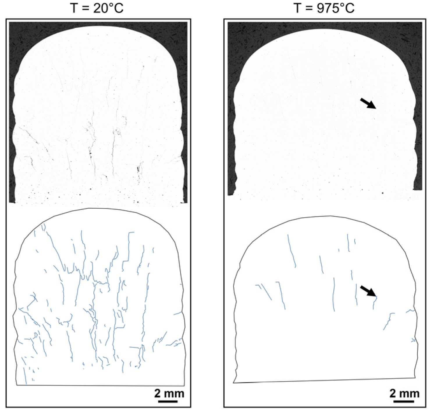
- Laser preheating strongly reduced the crack density for all tested conditions. Structures of dimension 14 mm × 7 mm × 15 mm built on a substrate at room temperature showed a crack density of 0.08 mm/mm2, while the deposition on preheated substrates led to microstructures without detected cracks. For the largest analyzed specimens, laser preheating led to a reduction in crack density by a factor of 5.3.
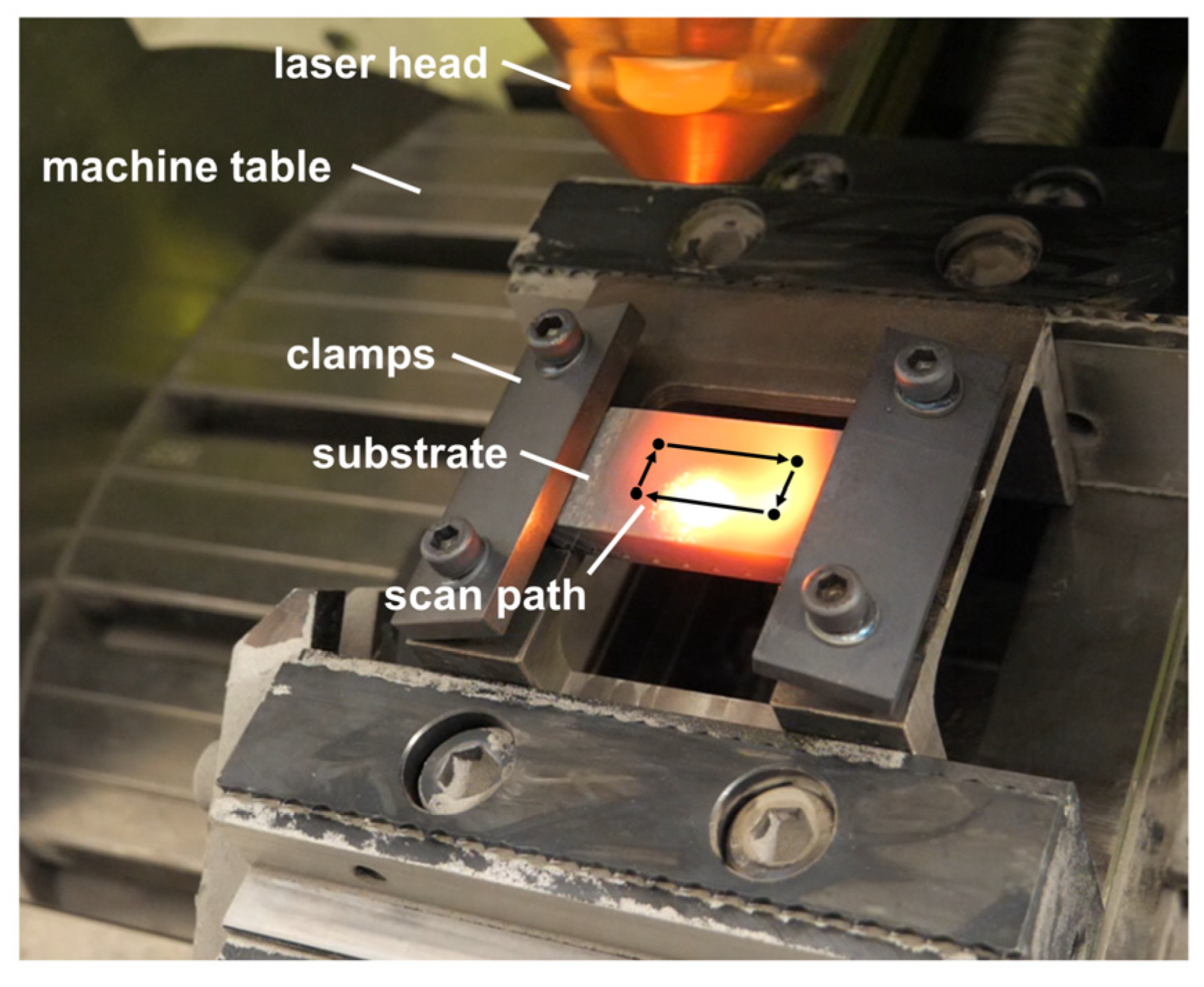
- The proposed process is implementable on existing DMD machines and does not require any additional hardware. Therefore, the laser preheating process appears to be economically feasible for the repair of super alloy components by DMD.
Author Contributions
Funding
Institutional Review Board Statement
Informed Consent Statement
Data Availability Statement
Acknowledgments
Conflicts of Interest
References
- DebRoy, T.; Wei, H.L.; Zuback, J.S.; Mukherjee, T.; Elmer, J.W.; Milewski, J.O.; Beese, A.M.; Wilson-Heid, A.; De, A.; Zhang, W. Additive manufacturing of metallic components—Process, structure and properties. Prog. Mater. Sci. 2018, 92, 112–224. [Google Scholar] [CrossRef]
- Xiong, Z.; Li, Z.; Sun, Z.; Hao, S.; Yang, Y.; Li, M.; Song, C.; Qiu, P.; Cui, L. Selective laser melting of NiTi alloy with superior tensile property and shape memory effect. J. Mater. Sci. Tech. 2019, 35, 2238–2242. [Google Scholar] [CrossRef]
- Elahinia, M.; Shayesteh Moghaddam, N.; Taheri Andani, M.; Amerinatanzi, A.; Bimber, B.A.; Hamilton, R.F. Fabrication of NiTi through additive manufacturing: A review. Prog. Mater. Sci. 2016, 83, 630–663. [Google Scholar] [CrossRef] [Green Version]
- Smelov, V.G.; Sotov, A.V.; Murzin, S.P. Particularly Selective Sintering of Metal Powders by Pulsed Laser Radiation. Key Eng. Mater. 2016, 685, 403–407. [Google Scholar] [CrossRef]
- Mazumder, J. Laser-aided direct metal deposition of metals and alloys. In Laser Additive Manufacturing; Woodhead Publishing: Sawston, UK, 2017; pp. 21–53. [Google Scholar] [CrossRef]
- Wirth, F.; Wegener, K. A physical modeling and predictive simulation of the laser cladding process. Addit. Manuf. 2018, 22, 307–319. [Google Scholar] [CrossRef]
- Wirth, F.; Arpagaus, S.; Wegener, K. Analysis of melt pool dynamics in laser cladding and direct metal deposition by automated high-speed camera image evaluation. Addit. Manuf. 2018, 21, 369–382. [Google Scholar] [CrossRef]
- Rettberg, R.; Kraenzler, T. Hybrid manufacturing: A new additive manufacturing approach for closed pump impellers. In Industrializing Additive Manufacturing; Springer: Cham, Switzerland, 2021; pp. 146–159. [Google Scholar] [CrossRef]
- Hosseini, E.; Popovich, V.A. A review of mechanical properties of additively manufactured Inconel 718. Addit. Manuf. 2019, 30, 100877. [Google Scholar] [CrossRef]
- Murzin, S.P.; Kazanskiy, N.L.; Stiglbrunner, C. Analysis of the Advantages of Laser Processing of Aerospace Materials Using Diffractive Optics. Metals 2021, 11, 963. [Google Scholar] [CrossRef]
- Zhong, M.; Sun, H.; Liu, W.; Zhu, X.; He, J. Boundary liquation and interface cracking characterization in laser deposition of Inconel 738 on directionally solidified Ni-based superalloy. Scr. Mater. 2005, 53, 159–164. [Google Scholar] [CrossRef]
- Montazeri, M.; Ghaini, F.M. The liquation cracking behavior of IN738LC superalloy during low power Nd:YAG pulsed laser welding. Mater. Charact. 2012, 67, 65–73. [Google Scholar] [CrossRef]
- Rickenbacher, L.; Etter, T.; Hövel, S.; Wegener, K. High temperature material properties of IN738LC processed by selective laser melting (SLM) technology. Rapid Prototyp. J. 2013, 19, 282–290. [Google Scholar] [CrossRef]
- Adegoke, O.; Andersson, J.; Brodin, H.; Pederson, R. Influence of Laser Powder Bed Fusion Process Parameters on Voids, Cracks, and Microhardness of Nickel-Based Superalloy Alloy 247LC. Materials 2020, 13, 3770. [Google Scholar] [CrossRef] [PubMed]
- Liu, S.; Yu, H.; Wang, Y.; Zhang, X.; Li, J.; Chen, S.; Liu, C. Cracking, Microstructure and Tribological Properties of Laser Formed and Remelted K417G Ni-Based Superalloy. Coatings 2019, 9, 71. [Google Scholar] [CrossRef] [Green Version]
- Liu, D.; Lippold, J.C.; Li, J.; Rohklin, S.R.; Vollbrecht, J.; Grylls, R. Laser Engineered Net Shape (LENS) Technology for the Repair of Ni-Base Superalloy Turbine Components. Metall. Mater. Trans. A 2014, 45, 4454–4469. [Google Scholar] [CrossRef]
- DebRoy, T.; Mukherjee, T.; Milewski, J.O.; Elmer, J.W.; Ribic, B.; Blecher, J.J.; Zhang, W. Scientific, technological and economic issues in metal printing and their solutions. Nat. Mater. 2019, 18, 1026–1032. [Google Scholar] [CrossRef] [PubMed]
- Kou, S. Predicting Susceptibility to Solidification Cracking and Liquation Cracking by CALPHAD. Metals 2021, 11, 1442. [Google Scholar] [CrossRef]
- Xu, J.; Lin, X.; Guo, P.; Dong, H.; Wen, X.; Li, Q.; Xue, L.; Huang, W. The initiation and propagation mechanism of the overlapping zone cracking during laser solid forming of IN-738LC superalloy. J. Alloys Compd. 2018, 749, 859–870. [Google Scholar] [CrossRef]
- Chauvet, E.; Kontis, P.; Jägle, E.A.; Gault, B.; Raabe, D.; Tassin, C.; Blandin, J.-J.; Dendievel, R.; Vayre, B.; Abed, S.; et al. Hot cracking mechanism affecting a non-weldable Ni-based superalloy produced by selective electron Beam Melting. Acta. Mater. 2018, 142, 82–94. [Google Scholar] [CrossRef]
- Grange, D.; Bartout, J.D.; Macquaire, B.; Colin, C. Processing a non-weldable nickel-base superalloy by Selective Laser Melting: Role of the shape and size of the melt pools on solidification cracking. Materialia 2020, 12, 100686. [Google Scholar] [CrossRef]
- Seidel, A.; Finaske, T.; Straubel, A.; Wendrock, H.; Maiwald, T.; Riede, M.; Lopez, E.; Brueckner, F.; Leyens, C. Additive Manufacturing of Powdery Ni-Based Superalloys Mar-M-247 and CM 247 LC in Hybrid Laser Metal Deposition. Metall. Mater. Trans. A 2018, 49, 3812–3830. [Google Scholar] [CrossRef]
- Engeli, R.; Etter, T.; Hövel, S.; Wegener, K. Processability of different IN738LC powder batches by selective laser melting. J. Mater. Process. Tech. 2016, 229, 484–491. [Google Scholar] [CrossRef]
- Engeli, R.; Etter, T.; Meidani, H. Gamma Prime Precipitation Strengthened Nickel-Base Superalloy for Use in Powder Based Additive Manufacturing Process. U.S. Patent US 2017/0021453 A1, 26 January 2017. [Google Scholar]
- Griffiths, S.; Ghasemi Tabasi, H.; Ivas, T.; Maeder, X.; De Luca, A.; Zweiacker, K.; Wróbel, R.; Jhabvala, J.; Logé, R.E.; Leinenbach, C. Combining alloy and process modification for micro-crack mitigation in an additively manufactured Ni-base superalloy. Addit. Manuf. 2020, 36, 101443. [Google Scholar] [CrossRef]
- Chiang, M.F.; Chen, C. Induction-assisted laser welding of IN-738 nickel–base superalloy. Mater. Chem. Phys. 2009, 114, 415–419. [Google Scholar] [CrossRef]
- Stueber, R.; Milidantri, T.; Tadayon, M. Welding High-Strength Nickel Base Superalloys. U.S. Patent US5374319A, 28 September 1990. [Google Scholar]
- Xu, J.; Lin, X.; Guo, P.; Hu, Y.; Wen, X.; Xue, L.; Liu, J.; Huang, W. The effect of preheating on microstructure and mechanical properties of laser solid forming IN-738LC alloy. Mat. Sci. Eng. A 2017, 691, 71–80. [Google Scholar] [CrossRef]
- Cloots, M.; Uggowitzer, P.J.; Wegener, K. Investigations on the microstructure and crack formation of IN738LC samples processed by selective laser melting using Gaussian and doughnut profiles. Mater. Des. 2016, 89, 770–784. [Google Scholar] [CrossRef]
- Ramakrishnan, A.; Dinda, G.P. Direct laser metal deposition of Inconel 738. Mat. Sci. Eng. A 2019, 740–741, 1–13. [Google Scholar] [CrossRef]
- Lee, Y.S.; Kirka, M.M.; Ferguson, J.; Paquit, V.C. Correlations of cracking with scan strategy and build geometry in electron beam powder bed additive manufacturing. Addit. Manuf. 2020, 32, 101031. [Google Scholar] [CrossRef]
- Cortina, M.; Arrizubieta, J.I.; Ruiz, J.E.; Ukar, E.; Lamikiz, A. Latest Developments in Industrial Hybrid Machine Tools that Combine Additive and Subtractive Operations. Materials 2018, 11, 2583. [Google Scholar] [CrossRef] [Green Version]
- Chen, K.-C.; Chen, T.-C.; Shiue, R.-K.; Tsay, L.-W. Liquation Cracking in the Heat-Affected Zone of IN738 Superalloy Weld. Metals 2018, 8, 387. [Google Scholar] [CrossRef] [Green Version]
- Leech, P.W. Laser surface melting of a complex high alloy steel. Mat. Des. 2014, 54, 539–543. [Google Scholar] [CrossRef]
- Soffel, F.; Lin, Y.; Keller, D.; Egorov, S.; Wegener, K. Laser Remelting Process Simulation and Optimization for Additive Manufacturing of Nickel-Based Super Alloys. Materials 2022, 15, 177. [Google Scholar] [CrossRef] [PubMed]
- Ojo, O.A.; Richards, N.L.; Chaturvedi, M.C. Contribution of constitutional liquation of gamma prime precipitate to weld HAZ cracking of cast Inconel 738 superalloy. Scr. Mater. 2004, 50, 641–646. [Google Scholar] [CrossRef]
- Higashi, M.; Yoshimi, K. Electron beam surface melting of MoSiBTiC alloys: Effect of preheating on cracking behavior and microstructure evolution. Mater. Des. 2021, 209, 110010. [Google Scholar] [CrossRef]


| Element | Al | C | Co | Cr | Mo | Nb | Ni | Si | Ta | Ti | W | Zr | Others |
|---|---|---|---|---|---|---|---|---|---|---|---|---|---|
| wt.% | 3.44 | 0.10 | 8.54 | 16.10 | 1.72 | 0.83 | Bal. | 0.09 | 1.73 | 3.41 | 2.55 | 0.06 | <0.19 |
| Specimen | L × W × H [mm3] | Parameter Set [-] | Scanning [-] | Substr. Temp. [°C] |
|---|---|---|---|---|
| S1 | 5 × 5 × 5 | P1 | 0°/90° | 20 |
| S2 | 5 × 5 × 5 | P2 | 0°/90° | 20 |
| S3 | 5 × 5 × 5 | P3 | 0°/90° | 20 |
| S4 | 5 × 5 × 5 | P4 | 0°/90° | 20 |
| S5 | 10 × 10 × 10 | P1 | 0°/90° | 20 |
| S6 | 10 × 10 × 10 | P2 | 0°/90° | 20 |
| S7 | 10 × 10 × 10 | P3 | 0°/90° | 20 |
| S8 | 10 × 10 × 10 | P4 | 0°/90° | 20 |
| S9 | 15 × 15 × 15 | P1 | 0°/90° | 20 |
| S10 | 15 × 15 × 15 | P2 | 0°/90° | 20 |
| S11 | 15 × 15 × 15 | P3 | 0°/90° | 20 |
| S12 | 15 × 15 × 15 | P4 | 0°/90° | 20 |
| S13 | 15 × 15 × 15 | P3 | 0°/90° | 975 |
| S14 | 14 × 7 × 15 | P3 | 0°/90° | 20 |
| S15 | 14 × 7 × 15 | P3 | 0°/90° | 975 |
| S16 | 14 × 7 × 15 | P3 | 80°/100° | 20 |
| S17 | 14 × 7 × 15 | P3 | 80°/100° | 975 |
| Parameter Set | Laser Power [W] | Scanning Speed [mm/min] | Powder Flow Rate [g/min] |
|---|---|---|---|
| P1 | 1000 | 250 | 2.0 |
| P2 | 1000 | 300 | 2.0 |
| P3 | 1000 | 250 | 2.5 |
| P4 | 1000 | 300 | 2.5 |
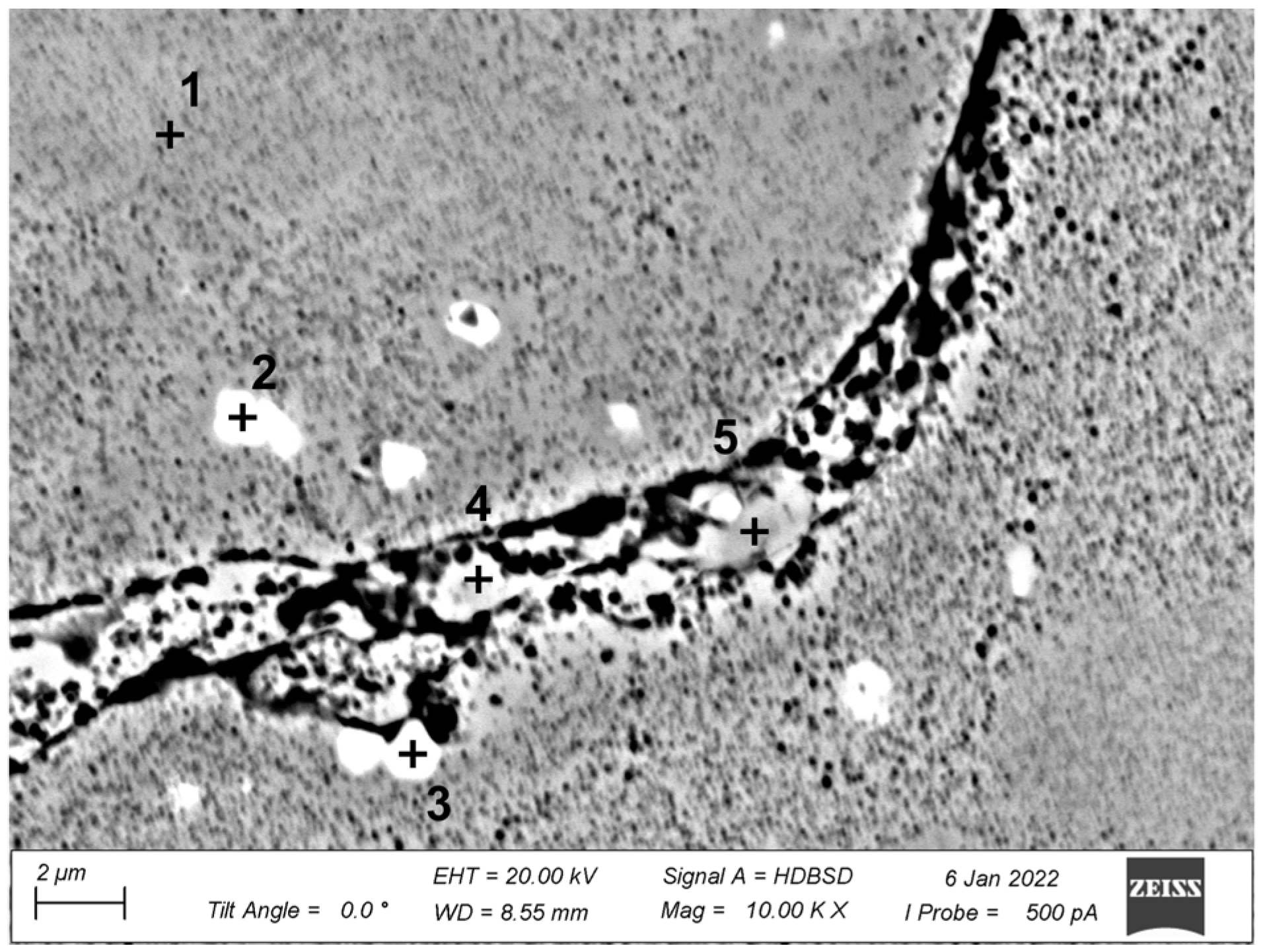
| Element | Al | C | Co | Cr | Nb | Ni | O | Ta | Ti | W |
|---|---|---|---|---|---|---|---|---|---|---|
| Point 1 | 3.1 | 4.4 | 8.4 | 16 | 0.5 | 57.6 | 0 | 1.9 | 2.6 | 3.3 |
| Point 2 | 0.3 | 12.5 | 1.8 | 4.6 | 9.3 | 11.0 | 0 | 25.5 | 25.3 | 6.0 |
| Point 3 | 2.6 | 9.0 | 2.6 | 6.1 | 10.3 | 18.3 | 7.1 | 21.1 | 14.3 | 4.6 |
| Point 4 | 3.1 | 5.0 | 7.8 | 15.2 | 0.8 | 55.5 | 2.2 | 2.1 | 3.3 | 3.0 |
| Point 5 | 3.0 | 4.6 | 7.7 | 15.1 | 0.7 | 55.5 | 2.9 | 2.3 | 3.5 | 2.7 |
Publisher’s Note: MDPI stays neutral with regard to jurisdictional claims in published maps and institutional affiliations. |
© 2022 by the authors. Licensee MDPI, Basel, Switzerland. This article is an open access article distributed under the terms and conditions of the Creative Commons Attribution (CC BY) license (https://creativecommons.org/licenses/by/4.0/).
Share and Cite
Soffel, F.; Papis, K.; Bambach, M.; Wegener, K. Laser Preheating for Hot Crack Reduction in Direct Metal Deposition of Inconel 738LC. Metals 2022, 12, 614. https://doi.org/10.3390/met12040614
Soffel F, Papis K, Bambach M, Wegener K. Laser Preheating for Hot Crack Reduction in Direct Metal Deposition of Inconel 738LC. Metals. 2022; 12(4):614. https://doi.org/10.3390/met12040614
Chicago/Turabian StyleSoffel, Fabian, Konrad Papis, Markus Bambach, and Konrad Wegener. 2022. "Laser Preheating for Hot Crack Reduction in Direct Metal Deposition of Inconel 738LC" Metals 12, no. 4: 614. https://doi.org/10.3390/met12040614