Article

Electron Backscatter Diffraction (EBSD) Analysis of Machinable Lead-Free Brass Alloys: Connecting Texture with Fracture

by
Athanasios Vazdirvanidis
,
Andreas Rikos
,
Anagnostis I. Toulfatzis
and
George A. Pantazopoulos
*
ELKEME Hellenic Research Centre for Metals S.A., 61st km Athens—Lamia National Road, 32011 Oinofyta, Greece
*
Author to whom correspondence should be addressed.
Metals 2022, 12(4), 569; https://doi.org/10.3390/met12040569
Submission received: 1 March 2022 / Revised: 15 March 2022 / Accepted: 25 March 2022 / Published: 28 March 2022
(This article belongs to the Special Issue Machinability and Tribological Performance of Advanced Alloys)

Abstract

:
The current paper is related to the study of the microstructure and texture of two machinable lead-free brass alloys, namely CuZn42 (CW510L) and CuZn38As (CW511L), which were evaluated in the as-drawn and post heat treated condition. Electron backscatter diffraction (EBSD) was employed for the examination of the brass rods’ crystallographic properties in order to correlate the effect of post processing heat treatment on the evolution of phase structure and texture towards the interpretation of dynamic (impact) fracture properties. It is shown that α- and β-phase volume fractions, mean grain size, and grain boundary misorientation are the most influential factors altering the fracture resistance of single- and dual-phase brass alloy rods. The role of grain boundary engineering, through the formation of coincidence site lattice (CSL) boundaries and their evolution during thermomechanical processing, is of major importance for the design of the mechanical behaviour of new eco-friendly machinable brass alloys.

1. Introduction and Literature Review

Brass alloys (Cu–Zn) are broadly used industrial metallic materials in domestic, mechanical, and electrical engineering as a result of their significant formability, corrosion and mechanical resistance, electrical conductivity, and, of course, high machinability [1,2,3]. Lead (Pb) is a basic alloying element of conventional brass due to its significant positive effect on machinability, resulting in high lubrication activity at the tool/workpiece interface and intense chip-fracturing, affecting the cutting tool service life and process [4,5,6,7]. However, the use of brass as a component in drinking water installations has increased the demands for the elimination of lead toxicity, inaugurating a new class of copper alloys, the eco-friendly or lead-free/low-lead brass alloys. A simple version of lead-free/low-lead machinable alloys include (almost) binary Cu–Zn systems, such as CuZn42 (CW510L) and CuZn38As (CW511L) (see [8,9,10]). New eco-friendly systems containing various (micro)alloying elements, such as Si, Ti, Bi, Sn, Mg, Sb, and Al aim, in their majority, to offer a significant advantage in chip breaking, replacing Pb with other intermetallic or second-phase particle constituents [11,12,13,14,15,16,17]. A recent review, summarizing the entire spectrum of such an extended family of copper alloys, highlighting the various technical approaches and machinability improvement strategies, outlines the necessity of the optimization of the manufacturing process towards the fabrication of eco-friendly components, satisfying the requirement of the relevant environmental and health and safety regulations [18].
Evidently, chip rupture constitutes a significant aspect of machinability performance and it is strongly related to the fracture properties of brass alloys under different loading conditions [7,19]. Therefore, the study of the fracture behaviour of leaded and lead-free/low-lead brasses constitutes a significant element, not only for the insightful understanding of the role of microstructure (e.g., lead particle size and distribution, phase structure, grain structure) on chip breaking, but also for the design and optimization of the machinability performance, without compromising the mechanical properties of the fabricated components [20,21].
Failure and embrittlement mechanisms, such as intermediate temperature embrittlement (ITE) and transgranular-to-intergranular fracture, together with properties-processing relationships, have been extensively studied in brass alloys systems (see [22,23,24,25,26]). Among the most typical failure mechanisms, dezincification, stress corrosion cracking (SCC), and liquid metal embrittlement (LME) causing hot-shortness due to localized (intergranular) Pb fusion and grain boundary decohesion are revealed in characteristic case histories studied in the authors’ Institute, and representative works are shown in [27,28,29].

2. Background Information and Research Objectives

The microstructure of common brass alloys typically consists of one (single-phase, α-brasses) or two (dual-phase, α + β brasses) phases, as is shown by the well-known binary Cu–Zn phase diagram [30]. The α-phase is rich in copper, contains less than 37 wt.% zinc, and has a face-centred-cubic (fcc) crystal structure. Single, α-phase alloys have moderate strength and excellent formability at room temperature due to their low stacking-fault energy (SFE < 10 mJ/m2) (see [31]). Therefore, they easily form twins and they can also form coincidence site lattice (CSL) boundaries.
At a higher zinc content, the β-phase is formed, which possesses a body-centred-cubic (bcc) crystal structure. The copper alloys which include a β-phase have excellent hot workability and machinability. The β-phase is also referred to as an intermetallic compound due to the almost 50–50 atomic stoichiometry of Cu and Zn. It is stable at 800 °C from 39 to 55 wt.% Zn and at 500 °C between 45 and 49 wt.% Zn [30].
Above the temperature of 470 °C, Cu and Zn atoms occupy random locations of the lattice, forming a disordered structure which is known as the β-phase, but below this critical temperature thermal vibrations are decreased and atoms take preferential sites, forming a long-range ordered structure known as the β’-phase. This is constituted by smaller regions of ordered structure called domains. Their boundaries are called antiphase boundaries (APBs) and they can be only observed with transmission electron microscopy (TEM). Quenching from the ordered β-phase region leads to fine domain size and increased hardness. The CuZn or β’-phase belongs to B2 super lattice materials, having a structure similar to that of FeAl [30,32].
Extrusion products with variable volume fractions of α- and β-phases can be produced by altering extrusion temperature. Higher extrusion temperatures favour the formation of a β-phase and result in alloys with a lower yield strength if the α-phase is considerably coarsened [25].
It has been shown that grain boundary engineering (GBE) can be performed in fcc metals of low stacking-fault energy (SFE) through thermo-mechanical processing (TMP) in order to improve their mechanical properties. The proposed mechanism is the formation of coincident site lattice (CSL) boundaries, through the development of annealing twin boundaries with low values of Σ, such as Σ3 boundaries, and its variants, Σ9 and Σ27, which together with low-angle grain boundaries (LAGBs; considered to have 5–15 degrees of misorientation) are resistant to intergranular cracking in comparison to the more brittle behaviour shown by high-angle grain boundaries (HAGBs), which have misorientation values larger than 15 degrees [33].
It has been found that one reason for the more brittle behaviour of HAGBs could be their tendency to attract segregated elements, as opposed to LAGBs and the CSL boundaries. When a crack is formed, propagation is preferential through the network of HAGBs, while the fracture mode can be altered from intergranular to transgranular when the crack meets LAGBs and CSL junctions. The amount of CSL boundaries is also linearly increased with decreasing mean grain size, enabling the manufacturing of fracture-resistant alloy products [34].
In dual-phase brass alloys, the grain boundaries’ “character” should be evaluated separately for the two distinct phases, since during deformation and post-processing annealing, the α- and β-phases show different tendencies in HAGBs formation, with the α-phase exhibiting a high volume fraction of CSL boundaries, depending on the thermo-mechanical process scheme and the β-phase random values of HAGBs, which are considered of minor importance in GBE.
The current research is a follow-up work, aiming to shed light, using texture analysis, on the alteration of fracture mechanics and failure mechanisms of environmentally friendly brass alloys under different processing conditions, i.e., as-drawn and heat treated [35].
As presented in [35], apart from the benefits in machinability of CW510L (CuZn42) and CW511L (CuZn38As) alloys provided by heat treatment through the increase and stabilization of β-phase content, controversial results were obtained in impact toughness testing:
-
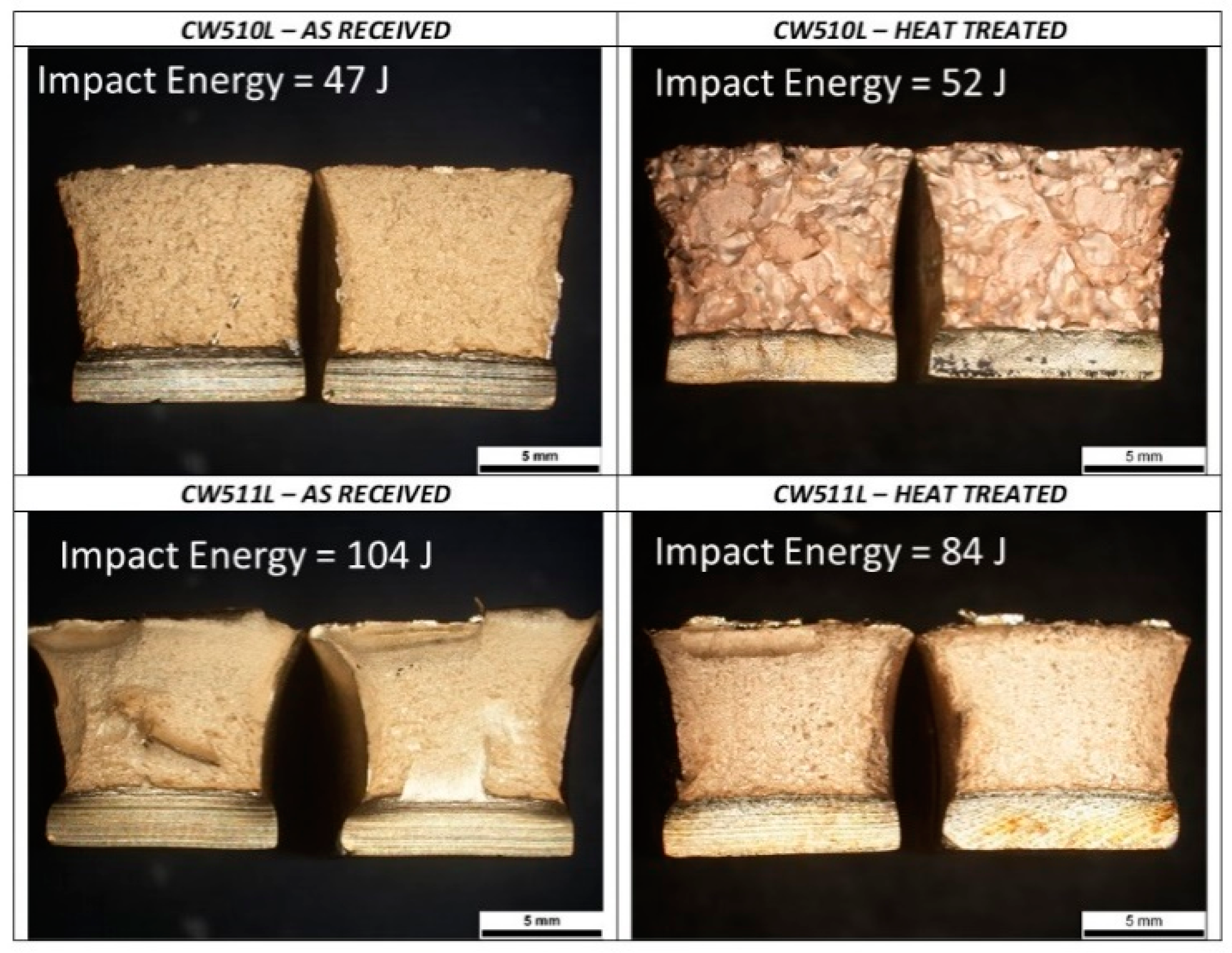
The CuZn42 alloy shows an increasing tendency (from 47 to 52 J).
-
The CuZn38As alloy shows a decreasing tendency (from 104 to 84 J)
The fracture surfaces of the respective Charpy specimens have also been studied in detail in [35]. The CuZn42 alloy sample in the as-received condition exhibited a typical, ductile fracture failure mechanism with multiple size dimples, while after the heat treatment it principally showed an intergranular fracture topography, with minute dimples on the grain facets. In the CuZn38As alloy sample, a fully ductile behaviour with multiple size dimples and large, deep voids was observed in the as-received condition as compared to the heat treated condition, where finer and shallower dimples were evident [35].
The present study is exclusively focused on electron backscatter diffraction (EBSD), in order to seek potential fracture–texture relationships that could justify the eminent evolution of fracture behaviour and crack propagation modes in the as-received and heat treated brass alloys. More specifically, further attention was placed on the salient interpretation of the observed “paradox” demonstrated by the CuZn42 sample, described as follows:
“The CuZn42 alloy after heat treatment exhibited improved fracture toughness, even though (i) the fully β-phase microstructure, established by the heat treatment, is expected to induce to fracture toughness deterioration and (ii) the obtained impact fracture topography presents an almost complete intergranular pattern which microscopically implies to lower impact energy.”
On the contrary, in the CuZn38As sample, the anticipated decrease in impact energy after the heat treatment was expected considering the attained phase transformations and the observed fracture mechanism demonstrated by the obtained fracture morphology which consists of smaller and shallower dimples.
To the best of the authors’ knowledge, there is no similar study concerning the investigation and interpretation of the fracture mechanisms of low-lead/lead-free brass alloys under various thermomechanical processing conditions (as-drawn and heat treated), using detailed texture and grain boundary analysis through electron backscatter diffraction (EBSD) analysis.

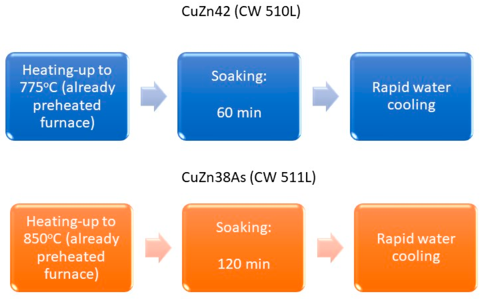
3. Materials and Methods

3.1. Brass Alloy Samples

Two distinct lead-free brass alloys were employed for the present study, namely CuZn42 (CW510L) and CuZn38As (CW511L). The chemical composition of the studied alloy samples is shown in Table 1 (see also [35]).
The samples are originated from 35 mm diameter extruded and drawn rods of two types of lead-free brass alloys, namely CuZn42 (CW510L) and CuZn38As (CW511L). The CuZn42 alloy rod was heat treated at 775 °C for 60 min and the CuZn38As at 850 °C for 120 min and they were both water quenched for maximization of the β-phase percentage and suppression of α-phase precipitation with the aim to improve machinability. A simple schematic showing the heat treatment processes for the different brass alloys is illustrated in Figure 1. The respective fracture surfaces after Charpy impact testing are shown in Figure 2.

3.2. Electron Backscatter Diffraction (EBSD)

EBSD analysis was performed in suitably sectioned impact-tested samples using an EDAX Hikari XP camera (EDAX, Mahwah, NJ, USA) mounted on a JEOL IT-800 HL (JEOL Ltd.,Tokyo, Japan) Scanning Electron Microscope (SEM), under 20 kV of accelerating voltage. A tilt of 70 degrees, 4 × 4 binning, and various magnifications and step sizes, depending on the grain size of the samples, prior to and following the heat treatment, were applied to assist in microstructure (phase structure), texture, and grain boundary analysis towards the interpretation of the alterations of fracture mechanisms.
Visualization of the strains caused by the impact tests, near the fracture surfaces, and examination of their distribution on the α- and β-phases, as well as the characterization and calculation of misorientation between adjacent grains, were performed. In the relative statistics, the 15° angle value was deployed as a distinction criterion of LAGBs from HAGBs.
Examination of the microstructure (phase structure) and fracture surface profile was performed in cross-sections parallel to the extrusion direction. The automatic collection and analysis of EBSD patterns was performed. Data mapping and information regarding the orientation, phase distribution, grain size, morphology, grain boundary, and local deformation of crystallographic regions was realized by using Orientation Image Mapping Software (OIM Analysis, version, EDAX, Mahwah, NJ, USA).
Coincident site lattice (CSL) boundaries are special character boundaries. These boundaries are classified in terms of Σ-values. The CSL boundaries are considered as special due to the fact that they possess a given fraction of atoms in the grain boundary plane which are coincident to both lattices which are separated by the grain boundary. The Σ-value denotes the fraction of atoms in coincidence. The detection of CSL boundaries is automatically performed by the OIM Analysis software.
The various EBSD settings used for the presented images/maps are summarized in Table 2.
Two representative EBSD scans per sample from the matrix in the as-drawn and heat treated conditions are shown concerning the phase structure examination. The following maps were acquired from each scan (the results are presented in Section 4.1):
  • An inverse pole figure (IPF-Z) map and texture plot for representation of the prevailing orientations. This was achieved after a 90° rotation of the original EBSD data, in order to create an equivalent to the transverse section image. Transverse sections are typically studied for the analysis of extruded and drawn products.
  • Phase mapping for calculation of the relative α- and β-phase volume fractions.
  • A grain boundary map for characterization of grain boundaries’ “character” and misorientation values between neighbouring grains.
One additional scan per sample of the fracture surface profile after Charpy impact testing in the as-drawn and heat treated conditions was performed and the retrieved results were as follows (the results are presented in Section 4.2):
  • Phase maps for the correlation of α- and β-phases with surface fracture topography.
  • Kernel average misorientation (KAM) maps for representation of the residual strains (deformation) underneath the fracture surface.

4. Results

4.1. Microstructure and Texture Characterization

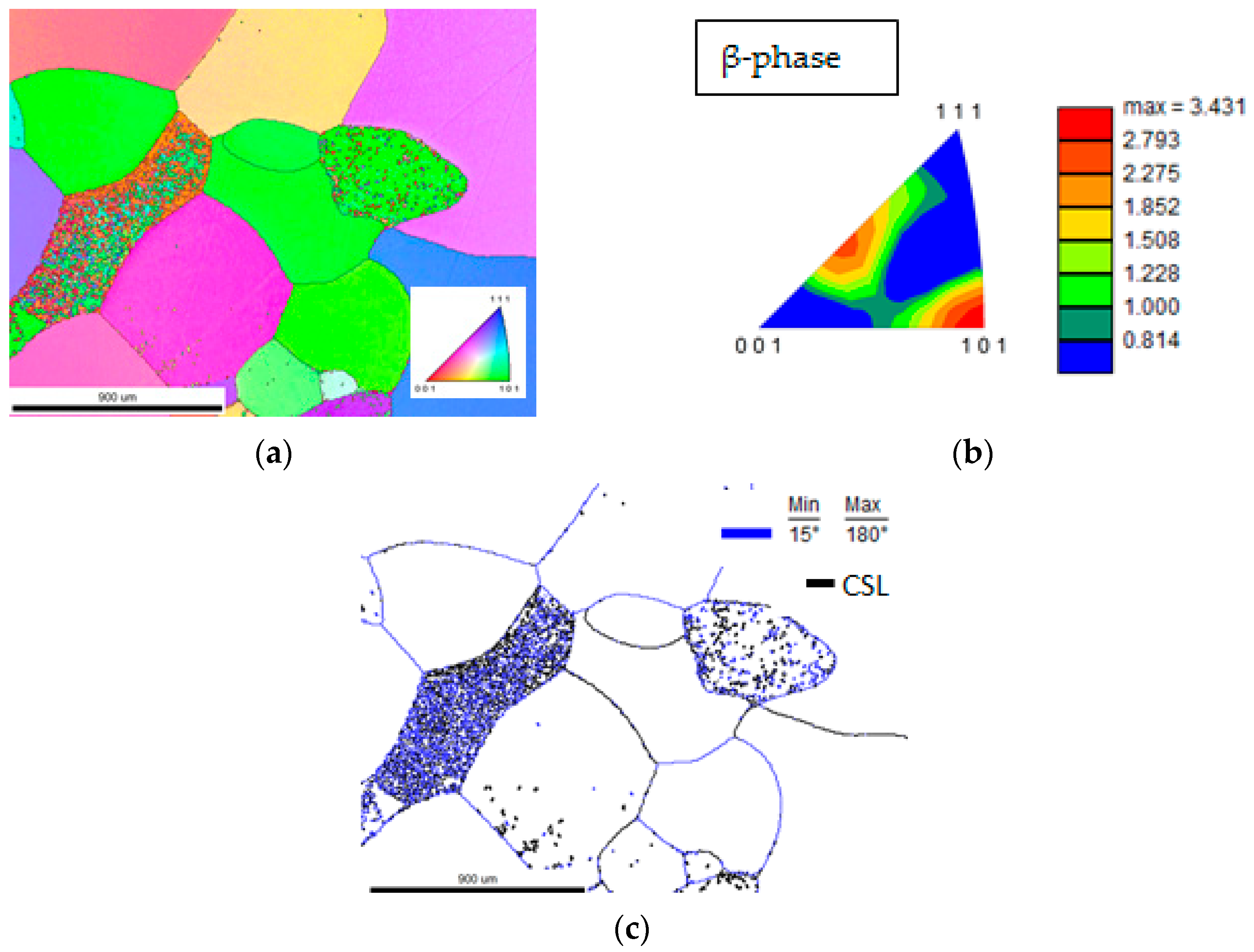
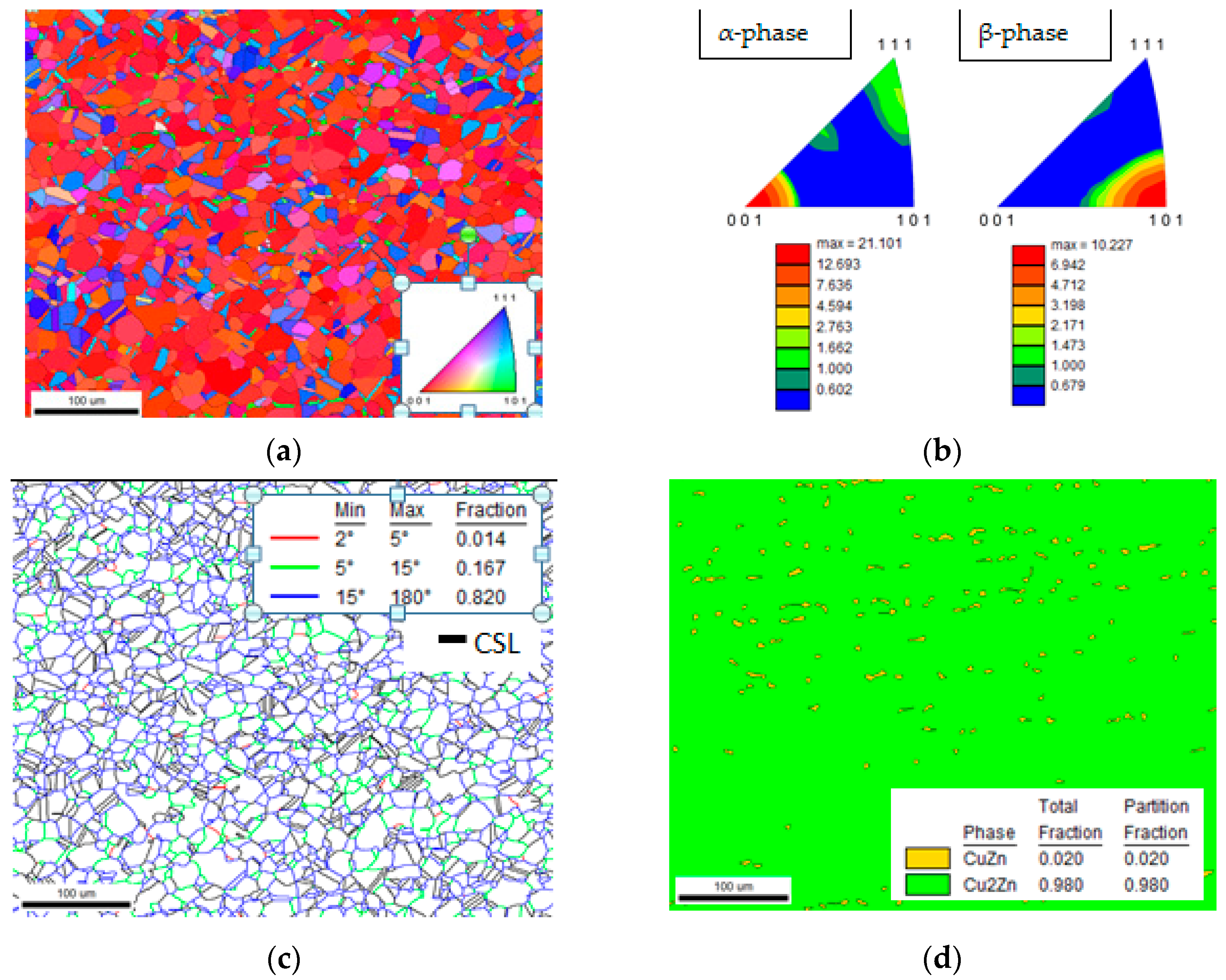
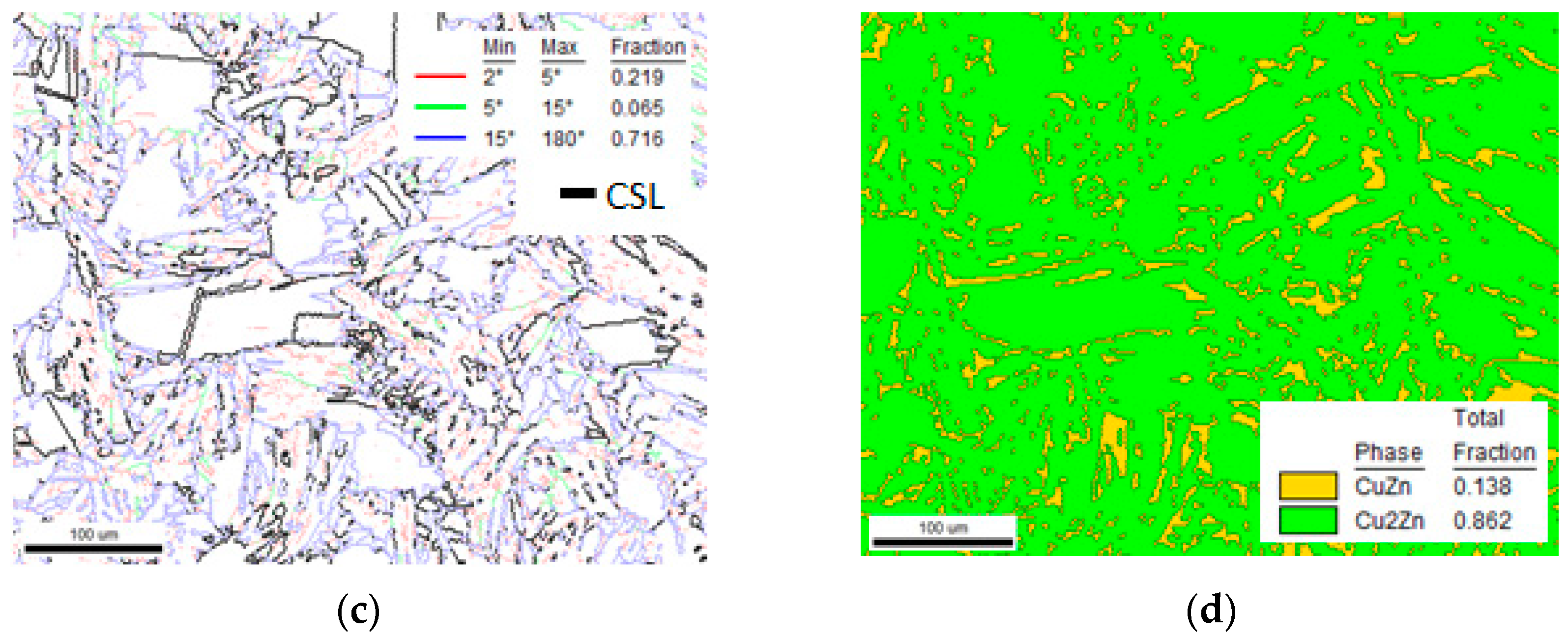
4.1.1. CuZn42—As-Drawn Condition

The texture and volume fraction percentages of the α- and β-phases in CuZn42 were determined by EBSD (see Figure 3 and Table 3). A (111) fibre structure was exhibited by the α-phase and a single (101) fibre with minor (335) preferred orientations structure was observed by the β-phase (see Figure 3a,b). The results showed a 46 vol.% fraction for the fcc (α-phase) and a 54 vol.% fraction for the bcc (β-phase) (see Figure 3d).
The α-phase appeared in various forms, mainly exhibiting an allotriomorphic morphology nucleated on the β-phase grain boundaries, but also as coarse intra-crystalline “islands”, typical of a slow cooling rate from a hot working temperature (Figure 3a). The mean grain size of both the α-phase and β-phases was 25 μm. A large fraction (20%) of the α-phase grains exhibited thermal or annealing twins. The microstructure was characterized by the presence of almost exclusively high angle grain boundaries (see Figure 3c and Table 4). No sub-grains (2–5 degrees) were detected, while low angle boundaries (5–15 degrees) were almost null and were located exclusively on α–α interface boundaries (see the green lines in Figure 3c). The high angle boundaries included 19% CSL boundaries, consisting of 10% Σ3 and the remaining 9% distributed to other CSL categories. All CSL high angle boundaries were related to the α-phase, while approximately half of them were located on α–β interphase boundaries, with the other half on α–α boundaries.

4.1.2. CuZn42—Heat Treated Condition

After the heat treatment, the microstructure consisted merely of macroscopic size (several thousand μm, i.e., mm) β-phase grains, while any α-phase precipitation had been suppressed by the rapid water quenching (Figure 4 and Table 3). A double (101) and (113) fibre structure was exhibited by the single β-phase alloy (Figure 4b). Exclusively high angle boundaries were observed (Figure 4c). The β-phase exhibited poor quality in EBSD scans in most of the grains, which rendered difficulties in processing the respective maps. This could be attributed to (i) the disorder–order transformation which led to fine ordered domain size and multiple orientations within a single grain or (ii) due to the minute lattice parameters deviation between the β- and β’-phase, which could not be resolved by the EBSD technique [36]. Interestingly, the examination showed that approximately 20% of the grain boundaries were CSL, with the higher percentage being Σ3 and the remainder being Σ7, Σ15, and Σ21 (Table 4). The coarse grain size is an indication of the exaggerated grain growth which took place during the heat treatment of the brass rod.
The quality of the β-phase regions in the EBSD maps in the as-drawn condition was higher than in the heat treated conditions, since any quenching effects resulting in fine domain sizes were avoided.

4.1.3. CuZn38As—As-Drawn Condition

The texture and microstructure of CuZn38As in the as-drawn condition is shown in Figure 5 and the summary of the results are listed in Table 3 and Table 4. The material was strongly textured with the (001) direction oriented parallel to the extrusion/drawing direction (Figure 5a,b). The microstructure consisted of partially recrystallized, equiaxed α-phase grains with a 14 μm mean grain size with a 98 vol.% fraction, while the β-phase was aligned parallel to the extrusion direction (longitudinal sections were performed). The volume fraction of the β-phase was 2% and its mean grain size was 3 μm (Figure 5d). An approximate 52% of α-phase grains exhibited thermal twins. A total of 1% of the grain boundaries constituted subgrain boundaries (2–5 degrees), 17% consisted of LAGBs, and the remaining 82% consisted of HAGBs (Figure 5c). The subgrain and LAGBs were detected within α-phase regions and could be considered as an indication of a fully recovered and partially recrystallized microstructure. The CSL fraction constituted 33% of the total boundaries, which were mainly encountered in the α-phase twins and on α–β interface boundaries in equal amounts. Approximately 22% of the total boundaries were Σ3, 3% were Σ5, and the remaining 8% was distributed to other categories (see Table 4).

4.1.4. CuZn38As—Heat Treated Condition

The texture and microstructure of CuZn38As in the heat treated condition are shown in Figure 6 and the results are summarized in Table 3 and Table 4. The α-phase exhibited a (001) and (335) double fibre texture with equal amounts of both directions while the β-phase was strongly textured with prevailing (101) directions and minor (112) (see Figure 6a,b).
After the heat treatment, the α-phase grains were coarsened, with a 23 μm mean grain size, and the fraction of the twinned grains was reduced to 21% (see Figure 6 and Table 3 and Table 4). The β-phase percentage was increased to 14% and the banding morphology was altered since a more uniform distribution of the β-phase was created. The β-phase mean grain size was 6 μm, which was double the size of that prior to the heat treatment condition, and it exhibited a plate-like, elongated morphology (Figure 6d). The grain boundaries’ character was also significantly altered by the heat treatment, i.e., 22% of the total boundaries were sub-grain boundaries, 7% were LAGBs, and the remaining 71% were HAGBs. Among them, 21% was characterized as CSL boundaries, with Σ3 and Σ49 occupying 8% of the total boundaries each, Σ5 and Σ9 occupying 3% in total, and the remainder being distributed to other categories (Table 4).

4.2. Microstructure Characterization of the Impact Specimens’ Fracture Surface Profile

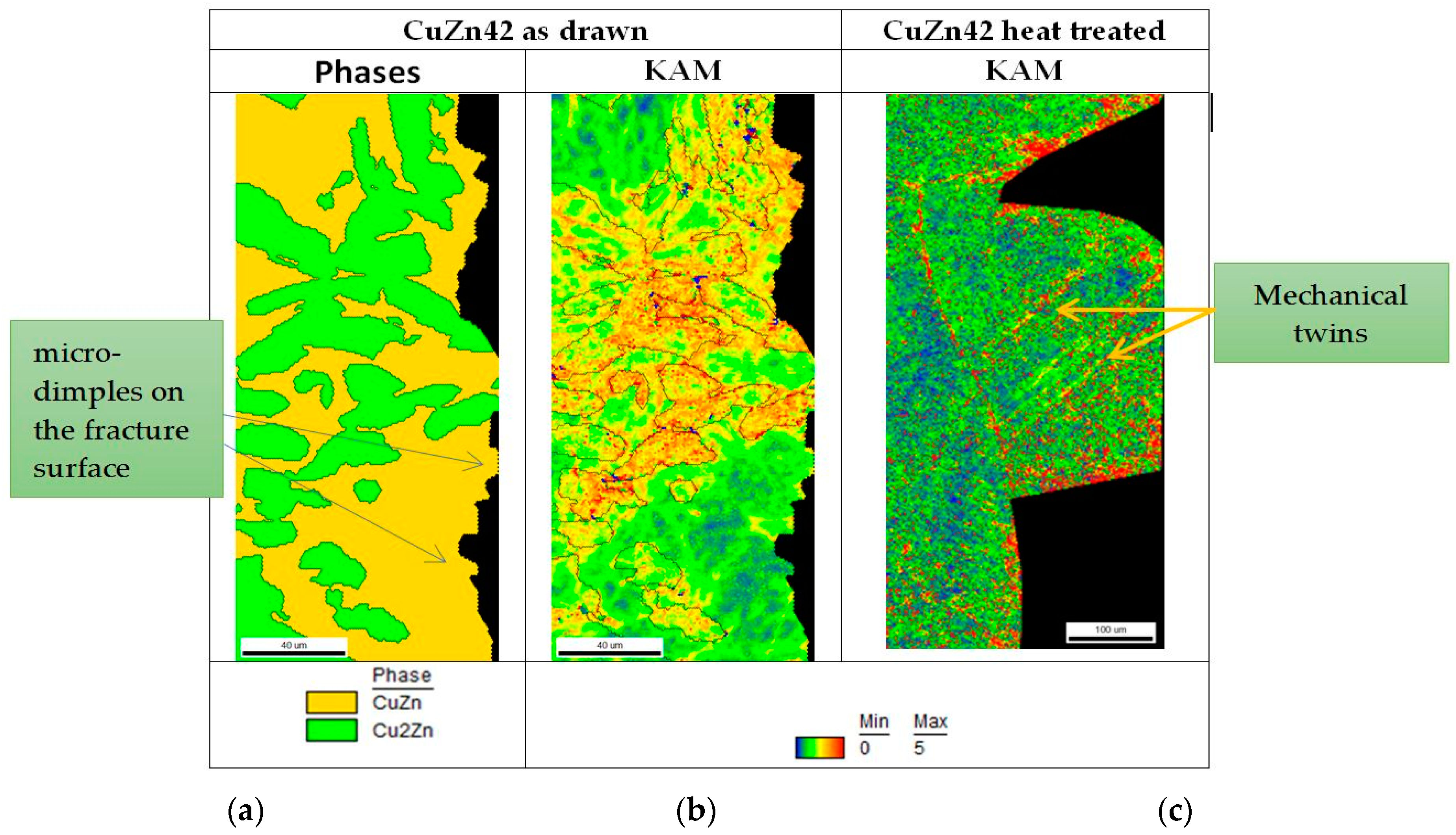
4.2.1. Sample CuZn42—As-Drawn and Heat Treated Conditions

The profile of the fracture surface of the impact test specimen in the as-drawn condition is shown in Figure 7a. The existence of micro-dimples was apparent as various size protrusions, not exceeding 2 μm. These protrusions did not exhibit the same amount of misorientation values in the KAM map, the latter being dependent on the phase where they were formed. The higher values were found by dimples formed within α-phase regions on the fracture surface or within the β-phase having a short distance from the α-phase, at maximum up to 10 μm. The α-phase network presented high misorientation values in the KAM map at even higher distances from the fracture surface.
In Figure 7c, the fracture surface profile of the CuZn42 alloy sample after the heat treatment is shown. It is typical of the occurrence of a brittle, intergranular fracture, with the presence of mechanical twins formed during the impact test. Mechanical twins can be produced in bcc metals under conditions of shock loading in decreased temperatures [31]. The “noise” in the map did not allow a definite recognition of deformed and non-deformed areas, but other than the angle boundaries which were high angle and lead to local high misorientation values, a uniform distribution of lattice rotations was observed, close and far from the fracture surface.
In Figure 8, lens-shaped twins are shown extending across the width of the grain (deformation twins do not extend to adjacent grains). This is the main existing deformation mechanism exhibited by the coarse, single β-phase brass alloy, since the crack tip created a limited plastic zone size compared to the grain size, hindering the activation of multiple sets of slip systems in adjacent grains, and dislocation emission was impeded by the existing microstructural barriers, causing dislocation pile-up to the activated slip systems and grain boundaries [37]. Twinning behaviour in bcc alloys is considered important in orientation changes that enable the activation of new slip systems in order to allow deformation by slip. In the intergranular crack, shown in Figure 8, on both the fracture surface and across the secondary crack, no appreciable deformation has occurred, leading to the hypothesis that mechanical twinning produced by the shock loading was the predominant deformation mechanism, explaining the reason for the uniform misorientation values for the same grain close and far from the fracture surface.

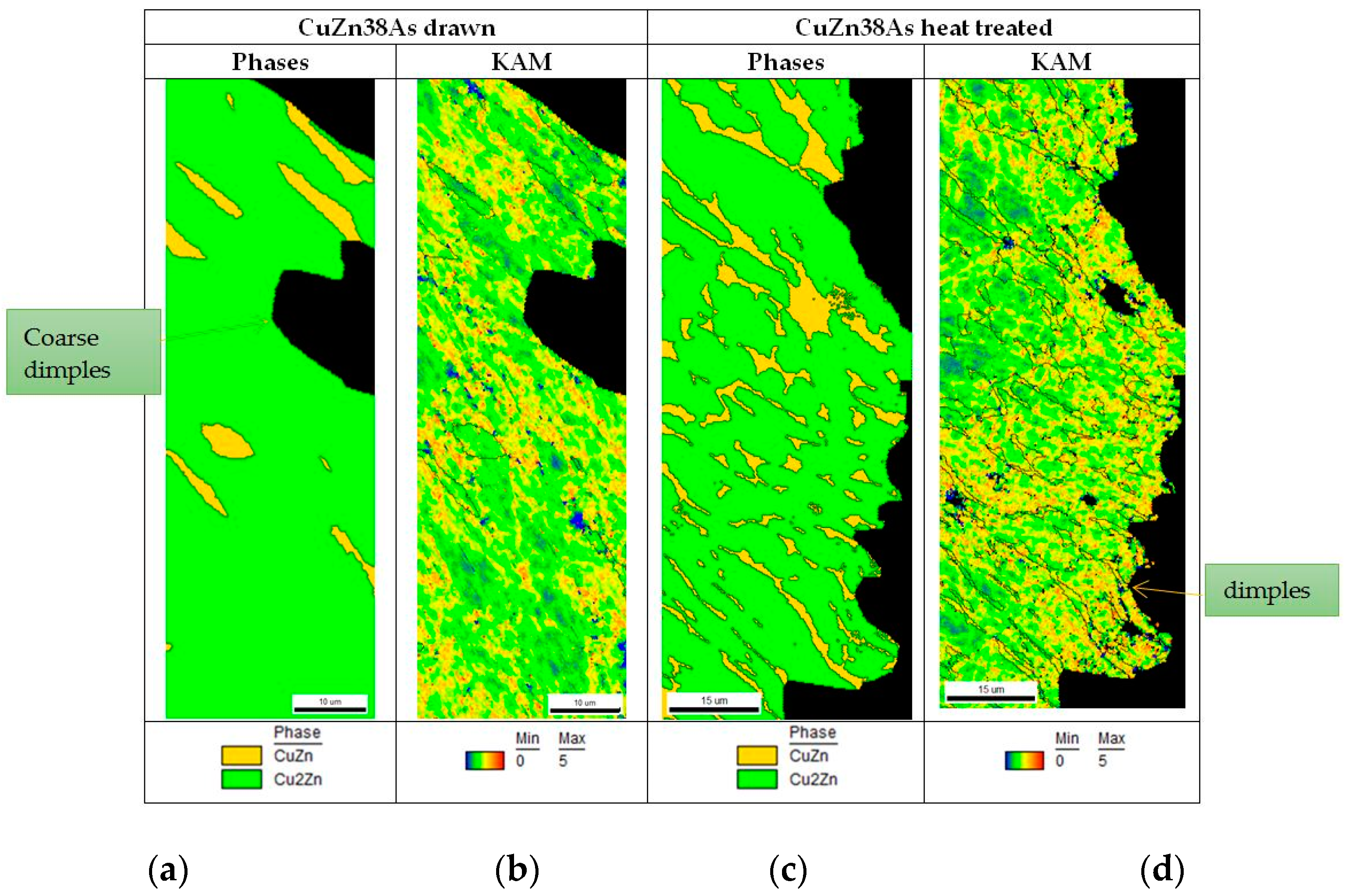
4.2.2. CuZn38As—As-Drawn and Heat Treated Conditions

The fracture surface profile of the sample in the as-drawn condition is shown in Figure 9a,b. It manifested appreciable ductility and the coarse formation of dimples reaching a size of 30 μm, which is multiple times the size of the dimples of the CuZn42 alloy in the same metallurgical condition. The equiaxed α-phase grains exhibited extensive strain markings close to the fracture surface as a contributing mechanism to the energy absorbance potential (Figure 10a). These constitute very fine deformation twins which are observed as a major deformation mechanism in low stacking-fault energy alloys such as the α-brass (20 mJ·m−2) [38]. The fine grain size of the α-phase grains contributed to improved ductility and the respective high energy values in the Charpy impact test (104 J).
In the heat treated condition, the fracture surface was also deformed, showing the presence of shallower dimples reaching a maximum size of 17 μm, since the more resistant to deformation β-phase did not allow the development of coarser dimples (Figure 9c,d). The α-phase grain structure, which was coarser (23 μm) than in the as-drawn condition, negatively affected the material’s deformation capacity during the impact test, leading to a lower energy absorption (84 J). Strain markings in the α-phase were also developed close to the fracture surface and were more readily observed in the coarser α-phase grains, especially in the heat treated condition (see Figure 10).

5. Discussion

The presented results, concerning the fracture behaviour of brass alloys, can be summarized and classified in two main categories: single-phase alloys and dual-phase (α + β) alloys.

5.1. Single-Phase Alloys: CuZn42, Heat Treated and CuZn38As, As-Drawn Condition

The CuZn38As sample, in the as-drawn condition, possessed a higher amount of α-phase (98 vol.%: it can be considered for simplicity purposes as a “single-phase” alloy) and a finer grain size, rendering a high deformation and energy absorbance capacity. Moreover, it contained the higher fraction of LAGBs and CSL boundaries (~50% in total), which promote ductile, transgranular fracture modes. The high extent of strain markings formation was an additional indication of a strained material with a high energy absorbance capacity.
The opposite condition was observed by the CuZn42 alloy sample in the heat treated condition, which showed a single β-phase structure and macroscopic grain size. These attributes favoured the development of mainly brittle intergranular cracking.
However, the average impact energy value for CuZn42 at the heat treated condition presented a slight increasing tendency (from 47 to 52 J; i.e., approximately 10%), compared with the same alloy at the as-drawn condition. The fact that CSL boundaries were detected (~20%) also led to the appearance of a minor transgranular crack propagation mode in the heat treated CuZn42 alloy. In addition, the occurrence of mechanical twinning constituted the dominant deformation mechanism of this sample with appreciable strain energy absorption during the shock loading. The incremental tendency of impact energy could potentially be explained by the following phenomena:
-
The presence of a significant fraction of CSL boundaries a (total of 20%, including a higher percentage of Σ3 boundaries up to 15%).
-
The mechanical twinning of the bcc β-phase.
In addition, the higher impact energy can be also supported by the higher hardness of the heat treated CuZn42 (fully β-phase) as compared to the as-drawn one, i.e., approximately 140 HV vs. 130 HV [35].
Grain boundaries are mostly influential on dynamic and static mechanical properties behaviour and can act as preferred locations for crack initiation and propagation. HAGBs hinder dislocation motion as a result of their high degree of misorientation, leading to dislocation pile-up and localized stress concentration that can induce failure [39]. In contrast, the slip systems of neighbour grains at LAGBs possess a higher alignment which favours dislocation mobility and retain slip homogeneity across the grain boundaries. Conclusively, LAGBs resist intergranular fracture, which tends to propagate along HAGBs [39].

5.2. Dual-Phase (α + β) Alloys: CuZn38As, Heat Treated Condition and CuZn42, As-Drawn Condition

Concerning the samples of CuZn42 in the as-drawn condition and CuZn38As in the heat treated condition, which constitute dual-phase alloys, the significant difference in energy absorbance capacity and dimple size, which are indicators of higher plasticity (for CuZn38As), seem to be related to the following factors (see also Table 3 and Table 4):
  • The increasing volume fraction of the α-phase (the CuZn42 alloy contains 46 vol.% α-phase and the CuZn38As alloy contains 86 vol.% α-phase) results in the amplification of impact energy from 47 and 84 J, respectively.
  • A decreasing β-phase mean grain size (25 μm for CuZn42 and 6 μm for CuZn38As) leads to a higher toughness (47 J and 84 J, respectively).
  • For the total amount of LAGBs plus CSL boundaries, a higher amount leads to a higher impact toughness (19% for CuZn42 as compared to 28% for CuZn38As), which promotes transgranular ductile fracture.
  • The existence of a subgrain structure (subgrain boundaries were mostly detected in CuZn38As under the heat treated condition, summed up to 22%).

6. Conclusions and Further Research

From the crystallographic examination of the single- and dual-phase brass rods, the following conclusions could be derived:
  • There is a strong tendency for energy absorbance in Charpy impact tests to be related to the amount of the sum of subgrains, LAGBs, and CSL boundaries. It is characteristic that the CuZn38As alloy under as-drawn and heat treated conditions, possessing in total 50% of the above interfaces, had the largest energy absorbance values (>80 J).
  • Σ3 was the predominant type of CSL boundary occurring in all the studied metallurgical conditions: (i) extruded and drawn and (ii) heat treated in the single-phase region and quenched.
  • Post processing heat treatment led to a single β-phase structure for CuZn42 alloy and a 12 vol.% increase for the β-phase in the CuZn38As alloy. The augmentation of the β-phase volume fraction inherits a negative effect on impact toughness for dual-phase brasses (α + β brasses).
  • The size of dimples and the prevalence of transgranular fracture mode in the Charpy impact test specimens’ fracture surfaces are strongly related with the amount of the α-phase volume fraction. Strain is also preferentially concentrated in α-phase regions on the fracture surfaces compared with the more brittle β-phase. KAM maps are advantageous in revealing the phases–strains relationships near the fracture surfaces.
  • In the absence of an α-phase, as in the case of CuZn42-heat treated condition, the fraction of dimpled fractures is negligible. On the other hand, in samples of CuZn42 in the as-drawn condition, CuZn38As in the heat treated condition, and CuZn38As in the as-drawn condition, as the α-phase volume fraction increases, the size of micro-dimples, viewed transverse to fracture surface sections, respectively increases.
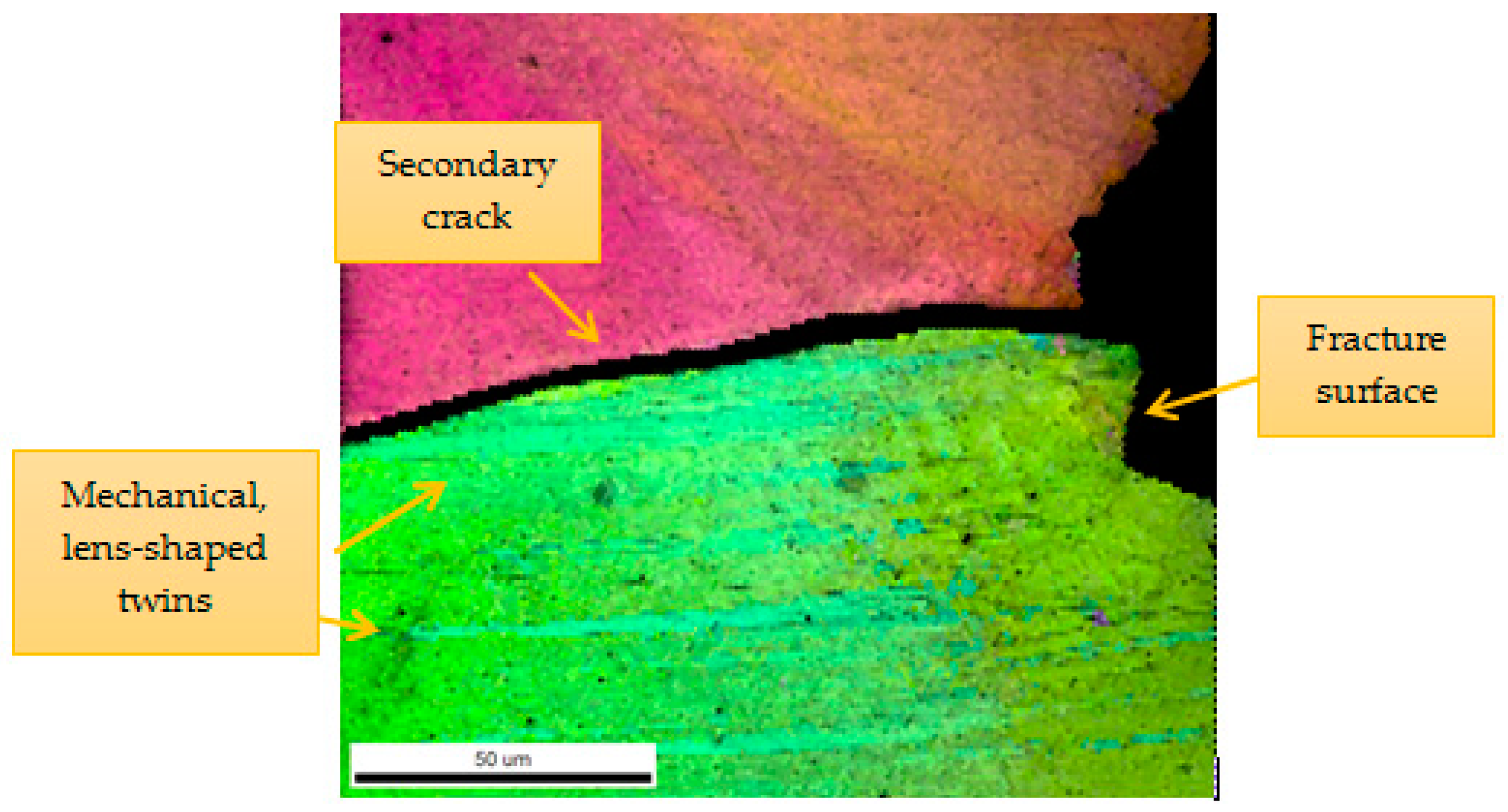
  • Interestingly enough, as it was obtained from the systematic impact energy results, the presence of a full β-phase microstructure could have a potential beneficial contribution to fracture toughness, due to the combination of higher hardness with the activation of the mechanical twinning process under shock loading conditions, while the limited size of the plastic zone ahead of the crack tip in combination with the coarse β-phase grains promotes intergranular crack propagation.
  • The increase of mean grain size of α- and β-phases offers a negative effect on strength and impact toughness in CuZn38As brass.
  • The texture of the α-phase in the as-received condition was different in the two different alloys, a single (111) in CuZn42 and (001) in CuZn38As, revealing a process and/or chemical composition relationship with the resulting texture. The dominant texture of the β-phase was (101) in both alloys and metallurgical conditions.
The fact that CSL boundaries were also observed in the single β-phase CuZn42 heat treated alloy, constituted mostly by Σ3 boundaries, offers a promising ground for further research since the investigation of the influence of texture on single β-phase properties will provide valuable knowledge towards the development of advanced copper alloys with superior mechanical behaviour and machinability.

Author Contributions

Conceptualization, A.V. and G.A.P.; primary materials testing and methodology, A.V., A.R. and A.I.T.; sample preparation, A.R.; writing—original draft preparation, A.V.; writing—review and editing, A.I.T. and G.A.P.; project supervision and management, G.A.P. All authors have read and agreed to the published version of the manuscript.

Funding

This research received no external funding.

Institutional Review Board Statement

Not applicable.

Informed Consent Statement

Not applicable.

Data Availability Statement

The data supporting the findings of this study are available upon request from the corresponding author.

Acknowledgments

The encouragement and support of ELKEME management is highly appreciated.

Conflicts of Interest

The authors declare no conflict of interest.

References

  1. Achiţei, D.C.; Minciună, M.G.; Vizureanu, P.; Sandu, A.V.; Cimpoeşu, R.; Istrate, B. Study on structure and properties of CuZnPb alloy. IOP Conf. Ser. Mater. Sci. Eng. 2019, 133, 012015. [Google Scholar] [CrossRef] [Green Version]
  2. Imai, H.; Kosaka, Y.; Kojima, A.; Li, S.; Kondoh, K.; Umeda, J.; Atsumi, H. Characteristics and machinability of lead-free P/M Cu60–Zn40 brass alloys dispersed with graphite. Powder Technol. 2010, 198, 417–421. [Google Scholar] [CrossRef]
  3. La Fontaine, A.; Keast, V.J. Compositional distributions in classical and lead-free brasses. Mater. Charact. 2006, 57, 424–429. [Google Scholar] [CrossRef]
  4. Wolfenden, A.; Wright, P.K. Role of lead in free-machining brass. Met. Technol. 1979, 6, 297–302. [Google Scholar] [CrossRef]
  5. Stoddart, C.T.H.; Lea, C.; Dench, W.A.; Green, P.; Pettit, H.R. Relationship between lead content of Cu-40Zn, machinability, and swarf surface composition determined by auger electron spectroscopy. Met. Technol. 1979, 6, 176–184. [Google Scholar] [CrossRef]
  6. Pantazopoulos, G. Leaded brass rods C 38500 for automatic machining operations: A technical report. J. Mater. Eng. Perform. 2002, 11, 402–407. [Google Scholar] [CrossRef]
  7. Johansson, J.; Alm, P.; M’Saoubi, R.; Malmberg, P.; Ståhl, J.-E.; Bushlya, V. On the Function of Lead (Pb) in Machining Brass Alloys. Res. Sq. 2022, Preprint. [Google Scholar] [CrossRef]
  8. Toulfatzis, A.; Pantazopoulos, G.; David, C.; Sagris, S.; Paipetis, A. Final heat treatment as a possible solution for the improvement of machinability of Pb-free brass alloys. Metals 2018, 8, 575. [Google Scholar] [CrossRef] [Green Version]
  9. Toulfatzis, A.I.; Pantazopoulos, G.A.; Paipetis, A.S. Microstructure and properties of lead-free brasses using post-processing heat treatment cycles. Mater. Sci. Technol. 2016, 32, 1771–1781. [Google Scholar] [CrossRef]
  10. Toulfatzis, A.I.; Pantazopoulos, G.A.; David, C.N.; Sagris, D.S.; Paipetis, A.S. Machinability of eco-friendly lead-free brass alloys: Cutting-force and surface-roughness optimization. Metals 2018, 8, 250. [Google Scholar] [CrossRef] [Green Version]
  11. Schultheiss, F.; Johansson, D.; Bushlya, V.; Zhou, J.; Nilsson, K.; Ståhl, J.E. Comparative study on the machinability of lead-free brass. J. Clean. Prod. 2017, 149, 366–377. [Google Scholar] [CrossRef]
  12. Nobel, C.; Klocke, F.; Lung, D.; Wolf, S. Machinability enhancement of lead-free brass alloys. In Proceedings of the 6th CIRP International Conference on High Performance Cutting, Berkeley, CA, USA, 23–25 June 2014; pp. 95–100. [Google Scholar]
  13. Atsumi, H.; Imai, H.; Li, S.; Kondoh, K.; Kousaka, Y.; Kojima, A. The effect of solid solutionizing Ti element on microstructural and mechanical properties of extruded Cu-40Zn-Ti ternary alloy. Trans. JWRI 2011, 40, 67–71. [Google Scholar]
  14. Suksongkarm, P.; Rojananan, S.; Rojananan, S. Bismuth formation in lead-free Cu-Zn-Si yellow brass with various bismuth-tin alloy additions. Mater. Trans. 2018, 59, 1747–1752. [Google Scholar] [CrossRef] [Green Version]
  15. Adineh, M.; Doostmohammadi, H. Microstructure, mechanical properties and machinability of Cu-Zn-Mg and Cu-Zn-Sb brass alloys. Mater. Sci. Technol. 2019, 35, 1504–1514. [Google Scholar] [CrossRef]
  16. Vilarinho, C.; Davim, J.P.; Soares, D.; Castro, F.; Barbosa, J. Influence of the chemical composition on the machinability of brasses. J. Mater. Processing Technol. 2005, 170, 441–447. [Google Scholar] [CrossRef] [Green Version]
  17. Rajabi, Z.; Doostmohammadi, H. Effect of addition of tin on the microstructure and machinability of α-brass. Mater. Sci. Technol. 2018, 34, 1218–1227. [Google Scholar] [CrossRef]
  18. Stavroulakis, P.; Toulfatzis, A.I.; Pantazopoulos, G.A.; Paipetis, A.S. Machinable leaded and eco-friendly brass alloys for high performance manufacturing processes: A critical review. Metals 2022, 12, 246. [Google Scholar] [CrossRef]
  19. Toulfatzis, A.I.; Pantazopoulos, G.A.; Paipetis, A.S. Fracture behavior and characterization of lead-free brass alloys for machining applications. J. Mater. Eng. Perform. 2014, 23, 3193–3206. [Google Scholar] [CrossRef]
  20. Toulfatzis, A.I.; Pantazopoulos, G.A.; Paipetis, A.S. Fracture Analysis of Eco-Friendly Brass Alloys: Comparison Study and Preliminary Assessment. In Proceedings of the 14th International Conference on Fracture (ICF 14), Rhodes, Greece, 18–23 June 2017. [Google Scholar]
  21. Pantazopoulos, G.A.; Toulfatzis, A.I. Fracture modes and mechanical characteristics of machinable brass rods. Metallogr. Microstruct. Anal. 2012, 1, 106–114. [Google Scholar] [CrossRef] [Green Version]
  22. Laporte, V.; Mortensen, A. Intermediate temperature embrittlement of copper alloys. Int. Mater. Rev. 2009, 54, 94–116. [Google Scholar] [CrossRef] [Green Version]
  23. Wolley, D.J.; Fox, A.G. The embrittlement of leaded and unleaded α+β (60-40) brasses in the temperature range 300 to 500 °C. J. Mater. Sci. Lett. 1988, 7, 763–765. [Google Scholar] [CrossRef]
  24. Felli, A.; Brotzu, A.; Pilone, P. Analysis of the fracture criticality of biphasic brass. Proc. Struct. Integr. 2016, 2, 2959–2965. [Google Scholar] [CrossRef] [Green Version]
  25. Mapelli, C.; Venturini, R. Dependence of the mechanical properties of an α/β brass on the microstructural features induced by hot extrusion. Scr. Mater. 2006, 54, 1169–1173. [Google Scholar] [CrossRef]
  26. Pantazopoulos, G. A review of defects and failures in brass rods and related components. Pract. Fail. Anal. 2003, 3, 14–22. [Google Scholar] [CrossRef]
  27. Pantazopoulos, G.; Vazdirvanidis, A. Identification of corrosion and damage mechanisms by using Scanning Electron Microscopy and Energy Dispersive X-ray Microanalysis: Contribution to Failure Analysis Case Histories. IOP Conf. Ser. Mater. Sci. Eng. 2014, 55, 012015. [Google Scholar] [CrossRef] [Green Version]
  28. Pantazopoulos, G.; Toulfatzis, A.I. Failure analysis of a machinable brass connector in a boiler unit installation. Case Stud. Eng. Fail. Anal. 2013, 1, 18–23. [Google Scholar] [CrossRef] [Green Version]
  29. Pantazopoulos, G.; Vazdirvanidis, A. Failure analysis of a fractured leaded-brass (CuZn39Pb3) extruded hexagonal rod. J. Fail. Anal. Prev. 2008, 8, 218–222. [Google Scholar] [CrossRef]
  30. Copper and Copper Alloys Specialty Handbook; ASM International: Materials Park, OH, USA, 2001.
  31. Dieter, G.E. Mechanical Metallurgy; McGraw-Hill Book Company: New York, NY, USA, 1988. [Google Scholar]
  32. Voort, G.F.V. ASM Handbook, Vol. 9; ASM International: Materials Park, OH, USA, 2004. [Google Scholar]
  33. Al-Fadhalah, K.J.; Aleem, R.M.; Nicky, T. Microstructure and texture development in thermomechanically processed leaded brass. Metals 2021, 11, 998. [Google Scholar] [CrossRef]
  34. Watanabe, T. Structural effects on grain boundary segregation, hardening and fracture. J. Phys. Colloques 1985, 46, C4-555–C4-566. [Google Scholar] [CrossRef]
  35. Toulfatzis, A.I.; Pantazopoulos, G.A.; Paipetis, A.S. Fracture mechanics properties and failure mechanisms of environmentally-friendly brass alloys under impact, cyclic and monotonic loading conditions. Eng. Fail. Anal. 2018, 90, 459–517. [Google Scholar] [CrossRef]
  36. Regina, J. Ordered Structures. In ASM Handbook, Volume 9: Metallography and Microstructures; ASM International: Materials Park, OH, USA, 2004. [Google Scholar]
  37. Janssen, M.; Zuidema, J.; Wanhill, R. Fracture Mechanics, 2nd ed.; SPON Press: Oxford, UK, 2004. [Google Scholar]
  38. Humphrey, F.J.; Hatherly, M. Recrystallization and Related Annealing Phenomena; Elsevier: Amsterdam, The Netherlands, 2004. [Google Scholar]
  39. Bond, D.; Zikry, M.A. Microstructural modeling of intergranular fracture in tricrystals with random low- and high-angle grain boundaries. JOM 2017, 69, 856–862. [Google Scholar] [CrossRef]
Figure 1. Simple schematic diagram showing the performed heat treatment processes (blue blocks for CuZn42 and orange blocks for CuZn38As alloy samples). Heat treatment conditions—CuZn42: 775 °C for 60 min followed by water quenching; CuZn38As: 850 °C for 120 min followed by water quenching.
Metals 12 00569 g001
Figure 2. Macroscopic fracture surfaces after impact fracture toughness tests (Charpy) before and after heat treatment of CW510L and CW511L brass alloys. The average values of the induced impact energies are referred too.
Metals 12 00569 g002
Figure 3. CuZn42 alloy in the as-drawn condition. (a) Inverse pole figure (IPF-Z) map and (b) texture plots. (c) Misorientation and (d) phase maps. The α-phase is precipitated in various morphologies from the β-grains. Note: CuZn (β-phase), Cu2Zn (α-phase). Unit: μm.
Metals 12 00569 g003
Figure 4. CuZn42 alloy in the heat treated condition. (a) Inverse pole figure (IPF-Z) map and (b) texture plot. (c) Misorientation map. The poor quality of the map was attributed to fine domain size within the macroscopic β-phase grains. Unit: μm.
Metals 12 00569 g004
Figure 5. CuZn38As alloy in the as-drawn condition. (a) Inverse pole figure (IPF-Z) map and (b) texture plot. (c) Misorientation and (d) phase map. Note: CuZn (β-phase), Cu2Zn (α-phase). Unit: μm.
Metals 12 00569 g005
Figure 6. CuZn38As alloy in the heat treated condition. (a) Inverse pole figure (IPF-Z) map and (b) texture plot. (c) Misorientation and (d) phases map. Note: CuZn (β-phase), Cu2Zn (α-phase). Unit: μm.
Metals 12 00569 g006aMetals 12 00569 g006b
Figure 7. Phase and KAM maps of the fracture surface profile of Charpy impact tested CuZn42 alloy samples: (a) phase map, (b) KAM map in the as-drawn condition, and (c) KAM map in the heat treated condition. Unit: μm.
Metals 12 00569 g007
Figure 8. Mechanical twins developed on the fracture surface of β-phase grains after Charpy impact test; CuZn42 alloy sample in heat treated condition, section transverse to fracture surface. Combined image quality and IPF map. Unit: μm.
Metals 12 00569 g008
Figure 9. Phase and KAM maps of the fracture surface profile of Charpy impact tested CuZn38As alloy samples in the (a,b) as-drawn and (c,d) heat treated conditions. Unit: μm.
Metals 12 00569 g009
Figure 10. Strain markings close to the fracture surface of (a) CuZn38As as-drawn and (b) CuZn38As heat treated alloy sample. EBSD image quality map. Unit: μm.
Metals 12 00569 g010
Table 1. Chemical composition of the brass alloy rods under examination (analysis by optical emission spectroscopy, elemental contents are expressed in wt.%).
Alloy (Spec. Limits)CuSnPbFeNiAlSbAsZn
CuZn4257.50.0060.100.030.0030.00020.0030.00142.4
(CW510L)
EN 1216457–590.30 max0.20 max0.30 max0.30 max0.050 max--Rem.
CuZn38As62.050.0040.090.020.0010.00020.0030.0337.8
(CW511L)
EN 1216461.5–63.50.10 max0.20 max0.10 max0.30 max0.050 max-0.02–0.15Rem.
Table 2. List of settings (scanned area, magnification, step size) used for the collection of the relevant EBSD patterns.
FigureScanned Area (μm2)MagnificationStep Size (μm)
Figure 3707 × 693100×3
Figure 41780 × 230050×7
Figure 5400 × 500150×0.8
Figure 6400 × 500150×2
Figure 7a,b100 × 240300×1
Figure 7c330 × 710100×2
Figure 8140 × 150370×1
Figure 930 × 90500×0.3
Figure 10a125 × 170180×0.4
Figure 10b70 × 75500×0.3
Table 3. Results of EBSD scans, % phase volume fractions, mean grain size, % twinned grains, and mechanical testing data.
AlloyMetallurgical ConditionPhasesMean Grainα-PhaseCharpy Test Results [35]
Twinned
Size (μm)Grains
vol.% αvol.% βαβ(%)Impact Energy (J)Fracture mode
CuZn42 (CW510L)As-drawn465425252047Ductile,
dimpled fracture
Heat treated-100-Macro (several thousand μm, i.e., mm) 52Intergranular
(predominantly)
CuZn38As (CW511L)As-drawn98214352104Ductile, dimpled
fracture (also including large, deep voids)
Heat treated86142362184Ductile, dimpled fracture (mostly shallow dimples)
Table 4. Results of EBSD scans, distribution of grain boundaries’ angles (%).
AlloyMetallurgical ConditionSub-Grain BoundariesLow AngleHigh AngleCSL
(2–5°)(5–15°)(>15°)
CSLRem.Σ3Σ5Σ9Σ49Rem.
CuZn42 (CW510L)As-drawn 1981102232
Heat treated 208015 5 (Σ7, Σ15, and Σ21)
CuZn38As (CW511L)As-drawn1173349223 8
Heat treated 227215081282
Publisher’s Note: MDPI stays neutral with regard to jurisdictional claims in published maps and institutional affiliations.

