Review

A Review of Corrosion under Insulation: A Critical Issue in the Oil and Gas Industry

1
Curtin Corrosion Centre, Curtin University, Perth, WA 6102, Australia
2
Department of Materials Science and Engineering, Monash University, Melbourne, VIC 3800, Australia
3
Department of Materials Science and Engineering, Massachusetts Institute of Technology, Cambridge, MA 02139, USA
4
Woodside Energy, Perth, WA 6000, Australia
5
Advanced Sensor Team, Research & Development Centre, Saudi Aramco, Dhahran 34464, Saudi Arabia
6
College of Engineering and Computer Science, Australian National University, Canberra, ACT 2601, Australia
*
Author to whom correspondence should be addressed.
Metals 2022, 12(4), 561; https://doi.org/10.3390/met12040561
Submission received: 7 January 2022 / Revised: 17 February 2022 / Accepted: 21 March 2022 / Published: 25 March 2022

Abstract

:
Corrosion under insulation (CUI) is defined as any form of external corrosion that occurs on the underlying metal beneath insulated equipment, due to water ingress through the insulation layer. This type of corrosion is frequently observed in oil and gas production, where insulated piping is prevalent, and has historically remained a predominant materials integrity issue. The prediction and direct visualisation of CUI are challenging tasks because of the coverage of the insulation layer(s) and any external jacketing or cladding. Several factors, including the local/ambient environment, system design, and the piping installation process, can influence how CUI initiates and propagates. In this review, CUI background, CUI monitoring, and CUI mitigation strategies are discussed.

1. Introduction

Corrosion under insulation (CUI) refers to a form of corrosion that typically occurs on carbon, low-alloy, and austenitic stainless steel equipment (e.g., piping systems, pressure vessels, and tanks) that is encapsulated with thermal insulation. Corrosion under insulation is thus a form of external corrosion (as opposed to corrosion that may occur on internal pipe walls) because it takes place on the outside of the metallic piping but beneath the insulating coating. The root cause of CUI is the penetration of water or condensed moisture into the insulation, which permeates the insulation. In such a case, water/moisture will make direct contact with the underlying metallic substrate and therefore aqueous corrosion, CUI, ensues [1,2,3,4]. In petroleum and chemical processing plants, CUI is a significant problem from a materials degradation standpoint; however, it may also lead to losses associated with equipment maintenance and replacement. Statistics provided by ExxonMobil document the economic impact of CUI, which approximates to 40–60% of piping maintenance expenditures [5,6,7]. In the case of carbon steel, corrosion rates under the insulation can be up to 20 times higher than those in naturally aerated atmospheric conditions. Consequently, CUI can give rise to severe ramifications if the issue is left unattended [6]. For example, in 2006, a leak that occurred in an aging petrochemical plant, caused by CUI, led to a fire that burnt half the processing unit with a cost of ~USD 50 million and also irreversible damage to the environment [8].
Before the 1970s, thermal insulation was predominantly used in high-temperature (>150 °C) applications for energy conservation. Therefore, CUI-related issues did not arise due to moisture evaporation at high temperatures. The wide application of thermal insulation in oil and gas plants can be traced back to the petroleum shortage in the 1970s when the application of insulation on piping and vessels at temperatures below 150 °C became a common practice to reduce energy costs [9]. Consequently, CUI became a more prevalent issue because water tends to be retained within the insulation at lower temperatures. While early CUI cases were reported in the 1950s, the associated industrial awareness and efforts to mitigate CUI did not begin until the 1980s [10]. The standard practice RP0198, which provided informative knowledge about the industrial practices for CUI mitigation, was officially published by the NACE International (now rebranded as AMPP) in 1998 [11], reaffirmed in 2004 [12], revised as SP0198 in 2010 [13] and again in 2017 [6].

2. Corrosion of Piping System under Insulation

The largest fraction of the piping in petrochemical and refining plants is made of either carbon and low-alloy steel (i.e., A53/A106, A335) or stainless steel (i.e., 3XX series such as 304 and 316 grades and duplex stainless steel). Different steel microstructures determine the type of corrosion that manifests in a CUI scenario. Corrosion that occurs on carbon steel can be uniform or localised, whilst corrosion that manifests on stainless steel is mostly localised in the form of pitting and stress corrosion cracking [14]. Stainless steel contains a minimum of ~11% chromium, which enables the formation of a thin oxide passive layer of Cr2O3 on top of the metal substrate. Alloy impurities such as manganese sulfide (MnS) and the Cr depletion in the vicinity of MnS are hypothesised as the critical causes for stainless steel pitting corrosion [15]. Duplex stainless steel, having a metallurgical structure consisting of two roughly equal proportions of phases—austenite and ferrite—and high chromium content (20–28%), possesses prominent corrosion resistivity [15,16,17,18]. Therefore, the chances of stainless steel suffering from CUI attack decrease. CUI is initiated by the retention of moisture/water within the thermal insulation and usually accelerates when the insulated equipment is operated under cyclic temperature and wet–dry cycles [4,14,19,20,21,22]. Water or moisture can be sourced from the ambient environment, e.g., rainfall, cooling towers, sprinkler systems, or from a condensation process.
The insulation is usually loosely packed and thus gaps are present at the pipe–insulation interfaces. These gaps can retain moisture, making the underlying metal vulnerable to corrosion. It is frequently observed that CUI comes into play where water can accumulate by gravity. For example, material damage is often observed at the bottom (6 o’clock position) of processing piping lines [23]. The proper piping structure design of the insulated operating system is essential to delay the onset of CUI and mitigate the potentially detrimental consequences caused by CUI.
A typical insulated pipe comprises an external jacketing/cladding, an insulation layer, a preventative coating layer, and the steel pipe (Figure 1). All these components are critical to understanding a CUI cycle. As follows, all of the influencing factors will be discussed.

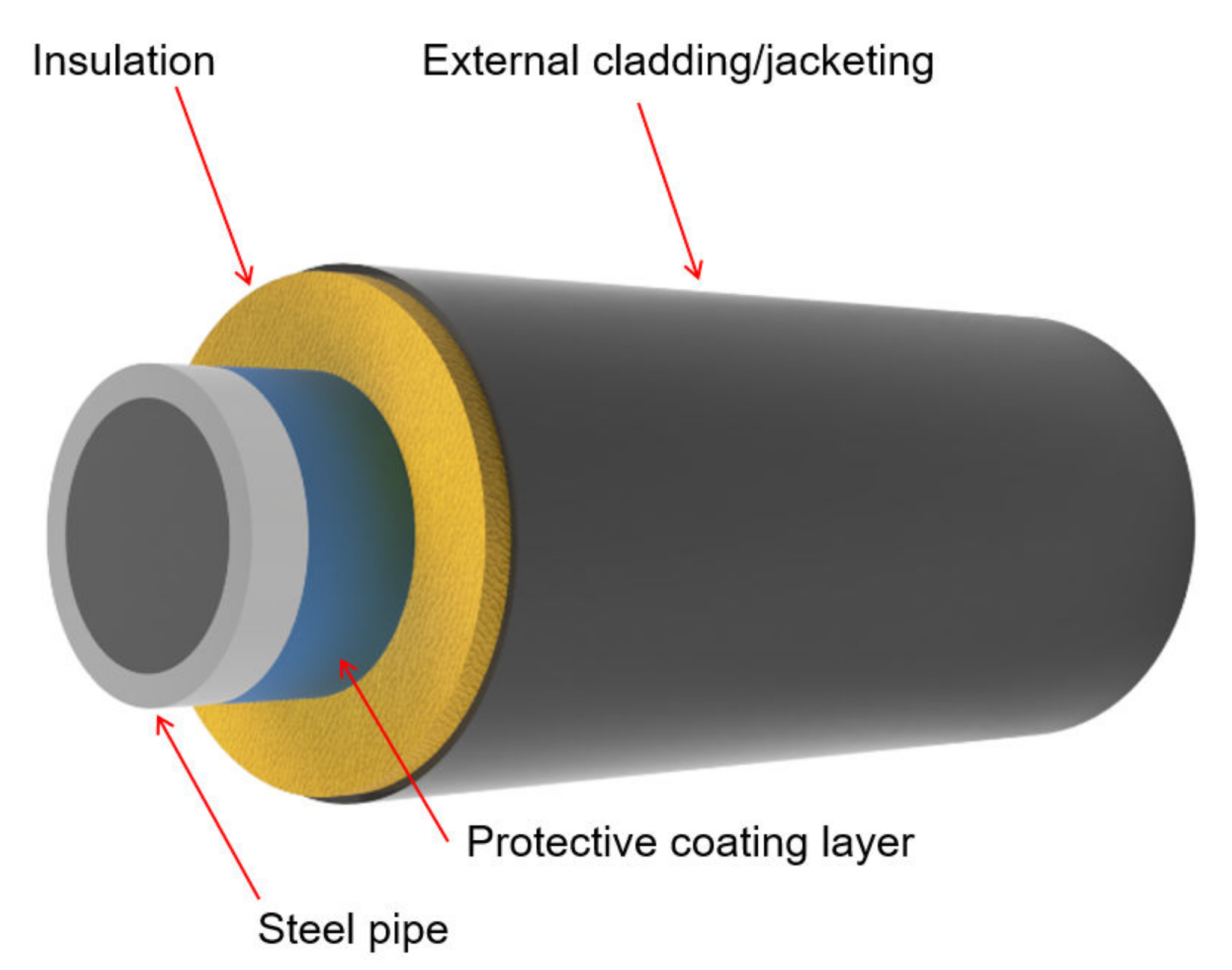
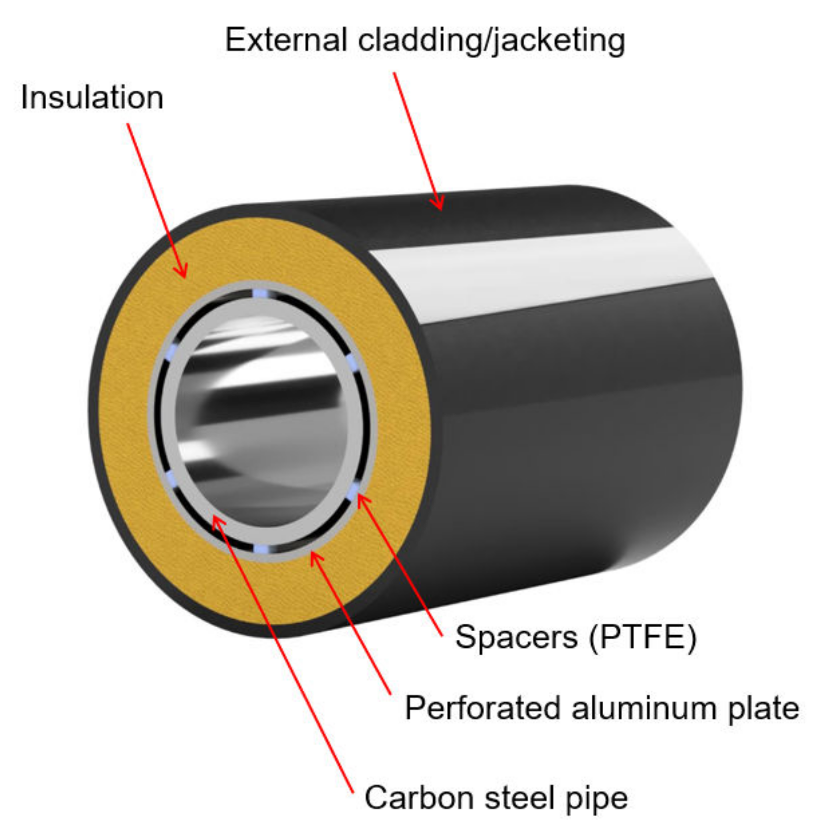
2.1. External Jacketing/Cladding

Jacketing/cladding provides external mechanical protection for pipes, valves, pumps, and other accessories. Jacketing is the first external line of defence of insulated equipment, with its other primary purpose to prevent water/moisture penetration into the existing insulated piping members. The American Petroleum Institute (API), in API RP 583 standard [24], classifies two major types of jacketing, namely, metallic and non-metallic. Metallic jacketing includes aluminium, galvanised steel, and stainless steel, while plastic/polymer jacketing is commonly used non-metallic jacketing (i.e., polyvinyl chloride) [24]. In general, non-metallic jacketing can be affected by UV radiation. Nowadays, aluminium, which has excellent formability, relatively high corrosion resistance, and low density (2.7 g/cm3), is a prevalently used metallic jacketing material. However, aluminium jacketing is susceptible to pitting corrosion and has low thermal durability [25,26,27]. Stainless steel, although costly, outperforms aluminium, especially under a severely corrosive environment and high-temperature atmospheres, where the use of aluminium is not recommended. Recently, fibre-reinforced polymer jacketing has been introduced in petrochemical plants as a new strategy to alleviate CUI. The new jacketing material is well known for its light weight, prominent corrosion resistance, and chemical resistance properties [28]. Recently, Mahdi et al. [29] applied an overwrap system to compare the corrosion protection efficiency offered by carbon-fibre-reinforced plastic (CFRP) and glass-fibre-reinforced plastic (GFRP). Four layers of corresponding CFRP and GFRP materials were wrapped around different steel pipes. The steel pipes were then subjected to immersion testing in 0.6 M NaCl for one year. The preliminary results show that the steel pipe was free of corrosion with a GFRP overwrap system [29].
Jacketing, joints, and other irregularities along the piping facility shall be adequately and carefully sealed. A high-quality sealing mitigates the ingress of ambient moisture. One case study reported a pipework failure in a chlorine distillation plant, where a significant amount of gaseous chlorine was released from the fractured pipe into the environment [14]. The leak was found from a perforation at the 3 o’clock position of the pipe. The deterioration of the sealing system was realised to be the root cause of the final failure. Consequently, water containing a high level of chlorides from the external atmosphere seeped through the degraded sealing materials and wetted the insulation, facilitating CUI.

2.2. Insulation Materials

Thermal insulation is a critical and essential component for energy conservation, fire protection, and personnel protection for petrochemical assets. Insulation materials are classified by their thermal properties, acoustic properties, water vapor permeability, hydrophobic properties, and fire protection capability [30]. The overall insulant thermal efficiency can be significantly reduced once water seeps into and is retained within the insulation. It is reported that the thermal conductivity of wet insulation is 15 times greater than that of dry insulation. CUI initiation and propagation rates are largely affected by the type of insulation used [4]. Presently, how to select the right insulation and how different insulation materials may affect the CUI cycles are arguably the least understood.
There is a wide range of insulation materials that are commercially available in the market, including fibreglass, mineral wool, cellulose ((C6H10O5)n), polyurethane (-NH-(C=O)-O- links the molecular units), polystyrene (aromatic hydrocarbon polymer made from the monomer styrene), foam glass, perlite (amorphous volcanic glasses), calcium silicate (Ca2SiO4) and aerogel blanket (an ultralight hydrophobic material) [31]. Of these, mineral wool is among the most prevalent, as it is more economical and readily available. Mineral wool is a fibrous material made from spinning and drawing molten rock [30].
Thermal conductivity, K, is often used to indicate the insulating capability of industrial thermal insulation. Thermal conductivity is defined as the total amount of heat that can be transferred through a unit area under a unit thickness during a certain time with the insulation assumed to be uniform [32,33]. In this regard, a small K value represents a better insulator performance in terms of energy saving [34]. K values of commercial insulations at varying temperature ranges are listed in Table 1. As seen, aerogel has the smallest K value and calcium silicate has the poorest insulation performance.
Appropriate thermal insulation selection is a major design concern because the type of insulation will determine the amount of water that can be absorbed and retained. Water vapor permeability evaluates the capability of a certain material to allow water vapor to pass through. Nash et al. [40] compared the water vapor permeability of various thermal insulation materials, among which mineral wool has the largest water vapor permeability (~170 × 10−12 kg/Pa·m·s at 23 °C). The ASTM C1511 standard offers a standard test method to quantify the water uptake characteristics of fibrous glass insulation, which could also be potentially employed to determine the water retention characteristics of other types of insulation [41].
Aerogel blanket—often considered “hydrophobic and breathable”, flexible and comparatively easy for installation—has been increasingly adopted for commercial and industrial applications [42,43]. The properties of aerogel insulation can vary drastically depending on its manufacturing methods and raw components. Among all types of different formulas, aerogels made from silica exhibit the lowest K values [44]. Silica aerogel, firstly discovered by Samuel S. Kistler in 1931, has a high density of nanopores that constitute 98% of its unit volume. The special structure makes silica aerogel ultra-lightweight and imparts its low thermal conductivity [45]. Compared with other insulation materials, aerogels are more expensive per unit area, and the handling of aerogels will produce dust that requires further health and safety considerations [46].
A “non-contact”, also known as a “distance-insulation” system, was recently proposed to delay the onset of CUI. Non-contact insulation is achieved through the separation of the insulation layer and piping substrate by creating a cavity, which allows moisture/water to evaporate faster, therefore delaying CUI initiation and reducing CUI rates. As illustrated in Figure 2, Haraldsen [47] used polytetrafluoroethylene (PTFE) spacers and perforated aluminium plates simulating the “non-contact” system. Experimental results indicate that the rate of CUI was significantly decreased when insulation was not in direct contact with the underlying substrate.
It is indicated that certain types of insulation themselves may leach corrosive components, i.e., chlorides and sulfates, subsequently facilitating CUI [1]. The ASTM C795 standard recommends a methodology to quantitatively determine the contents of leachable ions within the insulation. Insulation materials that leach chloride and fluorine exceeding a threshold shall not be used on stainless steel pipework [48]. Recent findings from Cao et al. [49] revealed that the rate of CUI increases due to the release of metal ions (Fe3+, Ca2+, Mg2+, and K+) from the moist insulation (Figure 3), contributing to an increased solution conductivity. Another finding was related to the formation of differential aeration cells during the non-homogenous packing of the insulation. Oxygen diffusion arising from the formation of differential aeration cells could influence the form of corrosion and corrosion rates of metallic piping substrate [49].

2.3. Design and Installation Deficiencies

Appropriate equipment and piping design can alleviate CUI [50]. Features including flat horizontal surfaces, angle-iron brackets, insulation support rings, and I-beams can introduce breaks and spaces that create an ideal reservoir for water/moisture retention [1,22,50]. The installation of intrusive parts, such as supplementary nozzles, pressure gauges, and fixings, can break the continuity of the weatherproofing layer on piping. The installation of external jacketing/cladding, insulation material, and protective coating layers must strictly follow the standardised procedures to minimise water/moisture ingress, and therefore, reduce CUI risks [1].
Poor installation of thermal insulation can lead to water/moisture infiltration. Water ingress may occur at the initial stage of equipment design or at a later stage during an inspection, where replacement and re-installation of the insulation are required when CUI is realised. It is essential to ensure that the installation and assembly of all parts meet the industry standard, without any significant damage to the overall integrity of the equipment [51].
Detrimental asset loss caused by CUI was observed and reported from multiple chemical processing plants. In 2013, a pipework failure led to a fire and subsequent explosion at a refinery [23]. The failure was noticed at the bottom dead center of a pipe section, and the pipe wall thickness was reported to have a significant reduction from 8 to 0.5 mm. Further investigation of the incident pointed to the neglect of design standards as the root cause of the failure. In this regard, a walkway bracket was installed at a distance to the insulated pipe far below the distance suggested, as shown in Figure 4. Consequently, water was retained between the jacketing and walkway bracket, leaving water to be easily accumulated within the reservoir and eventually causing corrosion [23].

2.4. Environmental Impacts on CUI

The exposure environment can be very complex—for both onshore and offshore piping facilities. The rate of CUI in thermally insulated equipment is largely influenced by temperature, wet–dry cycle, insulation types, rainfall, etc. [2,52]. The difficulty to predict CUI hinges upon the uncertainties surrounding the role of those environmental factors in the corrosion process. The form of corrosion and rates vary throughout the pipe’s entire length, which may be located at different atmospheres with various levels of corrosive exposure conditions [53]. In the case of liquified natural gas (LNG) production, natural gas is liquified down to ~−160 °C. In the overall process of gas transportation from offshore to onshore sites, the operating temperature is a critical factor to take into consideration in a CUI cycle.
As documented in NACE SP0198 and API RP583 standards, the riskiest temperature range for incubating CUI on carbon steel and austenitic/duplex stainless steel is 50–175 °C. In one reported case, a severe form of corrosion with a rate of 1 mm/year was noticed when the operating temperature was between 60 and 120 °C [54]. To be noted herein, the corrosion rates reported from lab-based experiments and field studies need to be considered differently. Based on ASTM G189, the lab-simulated CUI test is an accelerated test using synthetic seawater [55]. In the field scenario, the exposure atmosphere is geographically dependent and the nature of the corrosive medium that is condensed and retained within the annular space can be more complex. Corrosion rates collected from lab experimental tests are based on an average corrosion rate calculated from Equation (1).
Average   corrosion   rate   ( m m y ) = Δ W g × K   T h × A cm 2 × ρ g cm 3
where ΔW—mass loss, T—exposure time, A—area, ρ—density, and K = 8.76 × 10⁴ [56]. However, corrosion rates obtained from the site are determined through the maximum corrosion depth divided by exposure time [57]. In addition, the uncertainty arising from coating breakdown complicates the in-the-field CUI scenario. In general, corrosion rates increase with increasing operating temperature [6,22,24]. In the context of steel, its corrosion rate under the insulation is reported to increase proportionally with increasing temperature, as shown in Figure 5 [6].
It is widely accepted that the penetration of water/moisture into the insulated metal causes CUI. The amount of water/moisture retained within the insulation and how the water/moisture is distributed influence the process of CUI progression [4,14,24]. The morphology of the corrosion products formed upon the steel substrate can be general or local, which largely depends on the moisture distribution within the insulation. Moisture distribution within the insulation tends to be homogeneous when the percentage of moisture content is high. Therefore, a more generally distributed corrosion will be observed. Matsuda et al. analysed the corrosion depth of pipes in a chemical plant under operation for 40 years. A 25 vol% moisture content was reported to be a critical threshold value for the onset and propagation of severe CUI issues, with a corrosion depth over 1 mm. Additionally, a routine piping inspection was highly recommended if water content within the insulation was detected >15 vol% [57].
The pH value of the infiltrated water/moisture is another factor that influences CUI. Changes in water pH are sourced from external environments such as acid rain or a condensation process [6,24]. For carbon steel, higher pH values allow the build-up of a passive layer [6,22,24]. The corrosion of iron (Fe) is found to be more severe at pH < 4 due to the fast dissolution of ferrous oxide (FeO) in an acidic environment [58,59]. The metal ions’ leaching process is highly dependent on electrolyte pH [49]. In this regard, recent studies by Cao et al. examined the effect of moisture pH on the selective dissolution of metal ions from the insulation in a mineral-insulated carbon steel system [49]. In this study, an acidic solution was found to enhance the leaching process of metal ions such as Fe3+, Ca2+, Mg2+, and K+. On the contrary, the amount of leaching metal ions detected was reduced in an alkaline environment.
Chlorides and sulfates that are sourced from external or internal (insulation material) environments are principal contaminants causing CUI [6]. The interplay between chlorides and steel substrate influences the subsequent composition of corrosion products—α-FeOOH and iron oxides are predominant corrosion products when chloride concentration is at a low level; γ-FeOOH and β-Fe8O8(OH)8Cl1.35 are mainly found in the corrosion products when chloride concentration is high [59,60]. Sulfate (SO42−) species alter the redox potentials and promote the reaction of SO42−(aq) + Fe(S) ↔ FeSO4(aq) + 2e, accelerating the corrosion process [61]. In addition, several studies reported materials that contain silicate being used as corrosion inhibitors, especially for stainless steel, to combat stress corrosion cracking (SCC) [13,62,63]. Sodium silicate, for instance, is one of the most commonly used corrosion inhibitors. The dissolution of silicate ions increases the solution pH and promotes the formation of Fe2(SiO3)3—a protective layer that prevents chloride ions from attacking the stainless steel substrates [48]. Armstrong et al. [63] revealed that a modified silicate (CaO·xSiO2·nH2O) was capable of steel corrosion mitigation by releasing polysilicate anions, which can be further adsorbed at the steel surface to protect the substrate from ongoing corrosion.

3. CUI Inspection and Monitoring

Effective management, especially on the CUI high-risk regions (e.g., 6 o’clock location of insulated pipe, piping joint area, and the insulated facility near the sprinkler system, etc.), is essential to maintain the overall integrity of the insulated equipment. A lack of or insufficient inspection schemes can result in gas leaks and the loss of production. Nowadays, the major methodology used in the oil and gas industry to locate CUI is visual inspection, which requires partial or complete removal of the insulation. A typical process to conduct visual inspection requires inspectors to physically remove the external jacketing/cladding and strip off the insulation, then evaluate and assess the equipment’s surface condition, as shown in Figure 6. However, collateral costs associated with scaffold building, insulation removal, and reinstallation can be enormous [9]. Non-destructive testing (NDT) provides an effective and economic approach for end users to conduct corrosion detection without causing a major impact during operation. Some of the NDT methods enable CUI detection without removing external jacketing and insulation material. Commonly considered NDTs include infrared thermography, radiography examination, ultrasonic inspection, and eddy current, which will be detailed in the following sections.

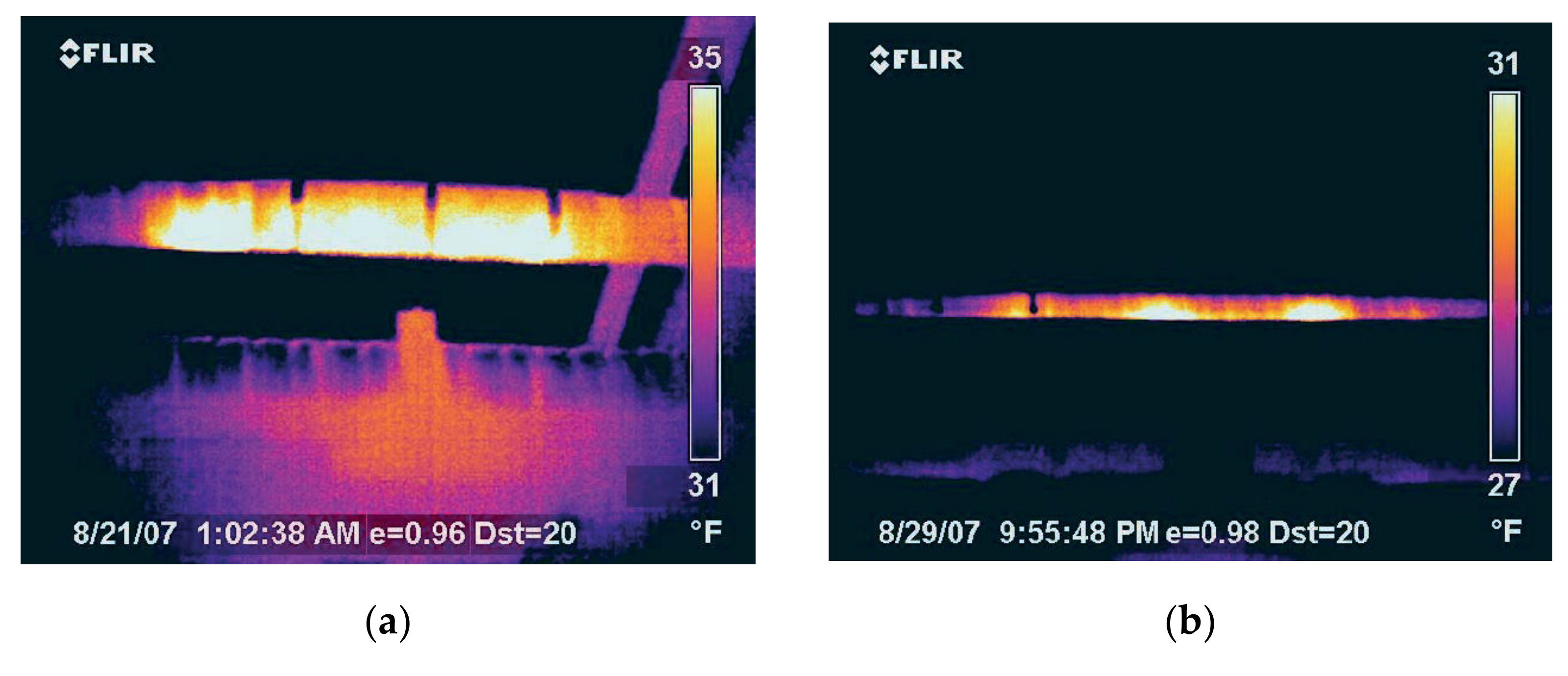
3.1. Infrared (IR) Thermography

IR thermography identifies locations that potentially experience CUI by analysing the temperature difference between dry and wet insulation. An IR camera can detect the infrared energy emitted from different objects and convert the energy information to a thermal temperature image. Temperature mapping can therefore indicate the location of wet insulation because wet or dry insulation conserves different thermal energy. Cadelano et al. showed that IR thermography has better accuracy and sensitivity to detect water close to the pipe surface (more internal location) than water that is located near the jacketing (more external location) [65]. IR thermography can be carried out remotely to diagnose CUI with apparatus installed on-site temporarily. However, the accuracy of IR thermography can be largely influenced by temperature, wind speed, insulation material, and pipe diameter, etc. [66]. It is also comparatively less economic than other types of NDT equipment [67,68]. Burleigh et al. [66] reported a field case of using the IR technique in Alaska. Images captured by the IR camera are shown in Figure 7, where the bright image region indicates the presence of water. A recent patent by Amer et al. [69] presented an advanced IR system that combined a modular vehicle and dual locomotion sensory systems (an infrared module and a pulsed eddy current module) to detect CUI.

3.2. Radiography Examinations

There are four types of commonly known radiography techniques: real-time radiography (X-rays), profile radiography (either X-rays or gamma rays), computed radiography (X-rays), and digital detector array (X-rays). Real-time radiography (RTR) uses X-rays or gamma rays to produce digital images [70]. X-rays can penetrate through the metallic objects and reflect on a receiver panel (e.g., C-arm), which contains microelectronic sensors to produce the image signals, as shown in Figure 8. Areas that experience external corrosion and subsequent wall thinning can be identified from the colour contrast of collected images. Thinner objects allow more radiation to pass through, hence, a larger amount of light can be emitted from the receiver panel, reflecting a lighter colour contrast on the image.
Profile radiography is an effective evaluation technique for wall thickness loss measurement. However, the overall measurement process is complex, involving extensive personnel contributions. The diameter of the pipe that can be examined with profile radiography is restricted to below eight inches, which limits the application of this type of NDT [9,71,72]. With a combination of real-time and profile radiography techniques, more accurate inspection results can be obtained [9].
Computed radiography uses a special photostimulable phosphor plate to collect incoming radiation, followed by the conversion of raw data to digital signal output using a photomultiplier. It produces high-quality images and meets the challenges to store and analyse data with a higher efficiency [73,74]. A digital detector array is known to be able to produce images with superior quality and less radiation impact [75].

3.3. Ultrasonic Inspection

Ultrasonic testing is a versatile non-destructive testing method for CUI inspection. Ultrasonic inspection can be performed locally in a confined area through point testing. Additionally, long-range ultrasonic testing can be used to inspect long pipes. Screening probes generate ultrasonic pulses to transmit through the objects. When ultrasonic waves encounter discontinuities such as water or a reduction in pipe wall thickness, these waves will be reflected back, collected, and further analysed [76]. The inspection coverage limit of long-range guided wave ultrasonic testing is 50 m [77]. In common practices, the frequencies of ultrasonic waves range from 0.1 to 50 MHz. Once the waves interfere with discontinuities, a different waveguide impedance can be detected [78,79]. The data interpretation is complex and must be delivered by a skilled technician [1,9,80]. Likewise, this technique is not suitable to examine parts having rough and non-homogeneous surface morphology [81]. An ultrasonic thickness gauge is often used as a fast-screening tool to detect the wall thickness loss; however, although it is more feasible in terms of point (local small area) detection, the results are not sufficiently reliable and representative for the whole equipment [82].

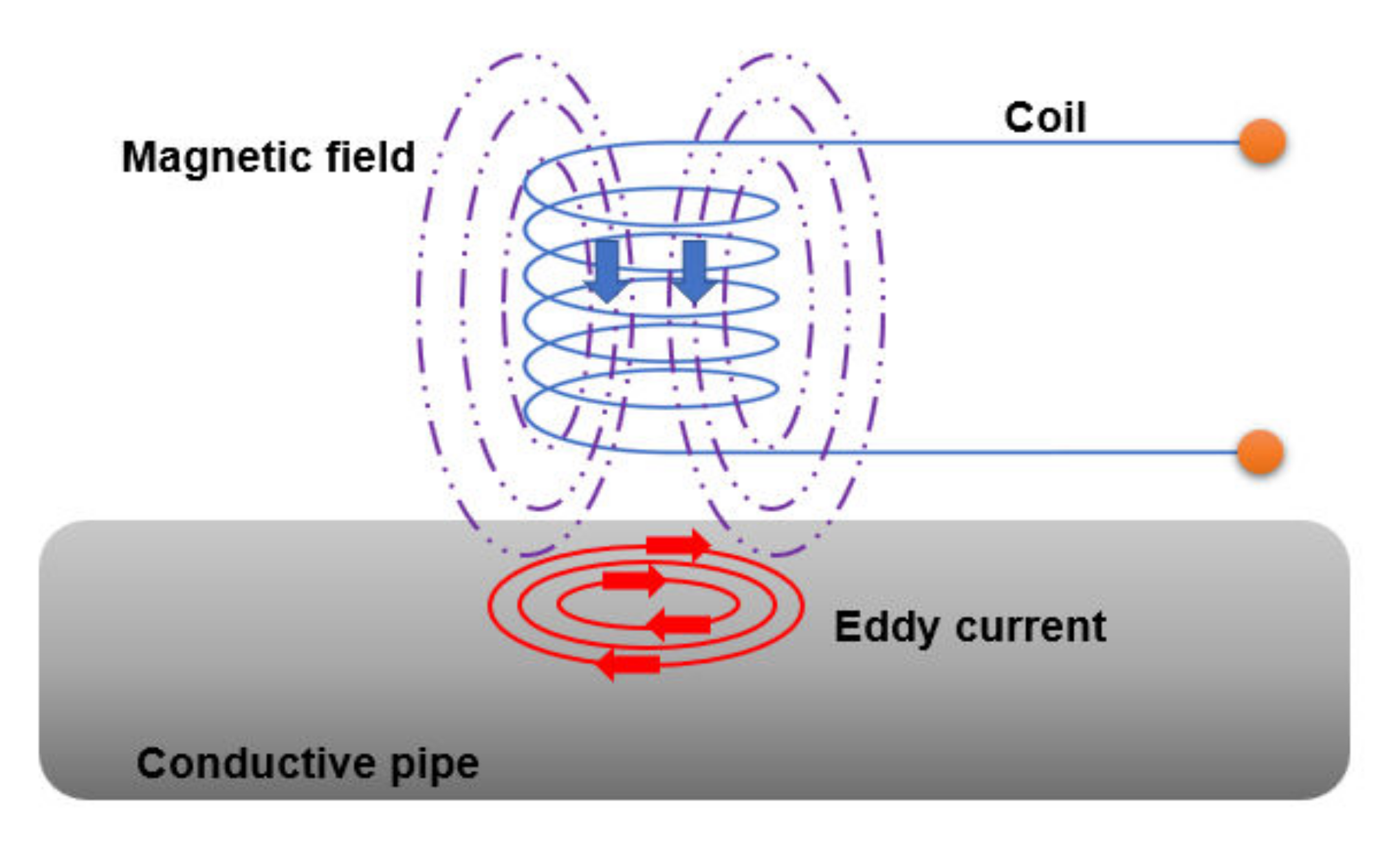
3.4. Pulsed Eddy Current

Pulsed eddy current measures wall thickness loss of piping by distinguishing variations in electromagnetic signals. Pulsed eddy current incorporates coil sensors and magnetic field sensors to locate CUI, as schematically depicted in Figure 9 [83,84]. By emitting an eddy current from an excitation coil towards the as-specified objects, a time-varying magnetic field signal can be reflected and further collected by the receiver coil. The magnetic field will change if defects or flaws exist [84,85,86]. Cheng et al. [85] reported a correlation between the signal decay coefficient and piping wall thickness loss; the feasibility of using a pulsed eddy current on different cladding materials was determined via mathematic simulation. Preliminary results indicate that the output signal was more intensive when the cladding material had a higher conductivity. It was also reported in the research that stronger signals were detected when aluminium alloy was used as cladding material rather than stainless steel cladding. In the case of insulated pipe with stainless steel cladding, the detected magnitude of electromagnetic signals was found to decrease with increasing piping wall thickness loss [85,87]. Compared with radiography, the eddy current technique has a higher inspection efficiency and poses a reduced occupation hazard risk. A highly skilled operator and essential training are required when conducting the measurement. Lastly, eddy current methods are inadequate to detect localised corrosion [82].

3.5. Neutron Backscatter

Neutron backscatter is a non-destructive technique that identifies the presence of moisture within the insulation, an indirect estimator of CUI risk. The functionality of the neutron backscatter technique is based on a collision between high-energy neutrons and nuclei of the specified material (e.g., carbon steel pipe surface) [88]. Those neutrons will bounce back after a collision and be collected by a detector. There is a high energy loss when neutrons interact with light atoms, such as the hydrogen nuclei within the water. Neutron backscatter is particularly sensitive to detect the presence of water and the amount of water within the insulation, hence, the subsequent likelihood of CUI [89,90]. The equipment can usually access congested areas and is easy to operate.

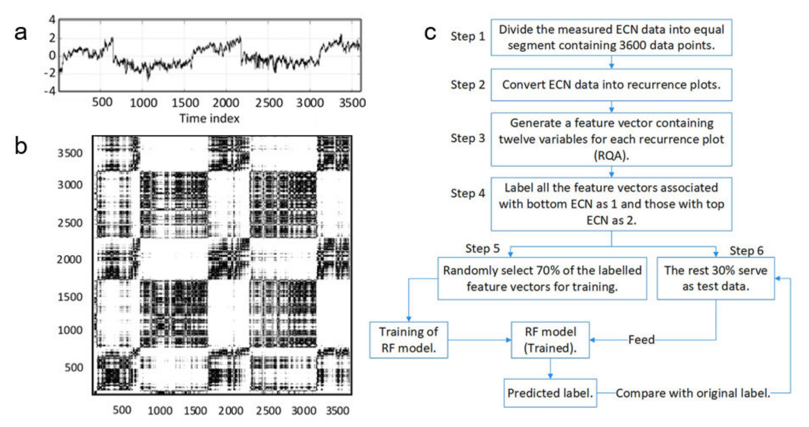
3.6. Electrochemical and Electrical Methods

Electrochemical noise and electrical resistance techniques have gained increasing consideration for CUI monitoring—especially in the scope of laboratory testing. Recently, Aung et al. [91] developed a novel electrochemical method through the invention of wire beam electrodes (WBE) and the combination of electrochemical noise signature analysis. Each WBE is a working electrode (material: aluminium AA1100), which consists of 100 wires for current and potential distribution measurement. The electrochemical noise activity is determined through the open circuit potential measurement between each wire against a saturated calomel reference electrode. It was found that the WBE sensor was able to distinguish the corrosivity of contact electrolyte via the vibrant potential/current changes caused by the direct corrosion of wire beams. Electrochemical current noise techniques have demonstrated their popularity in localised corrosion identification [92,93]. Hou et al. used the electrochemical current noise methodology, in combination with recurrence quantification analysis, to develop a random forest model for the identification of the form of corrosion present beneath the mineral wool insulation [94]. The key steps included training a random forest model using noise data as input, converting data into the recurrence plot, extracting feature variables, training the model, and validating the model accuracy. The detailed procedure is listed in Figure 10a–c.
The electrical resistance (ER) technique is capable of monitoring the wall thickness loss and corrosion rates of any metallic equipment. Metal substrate wall thinning is related to a proportionate increase in its electrical resistance value. The versatile ER method enables corrosion measurement in an electrolyte that has poor and non-continuous conductivity [95]. ER methods are predominantly employed for spot corrosion examination; therefore, to cover long-range piping inspection, multiple sensors are required to be installed at expected locations. From a cost and safety perspective, sensors should be intrinsically safe and cost effective to be used in an oil and gas plant.

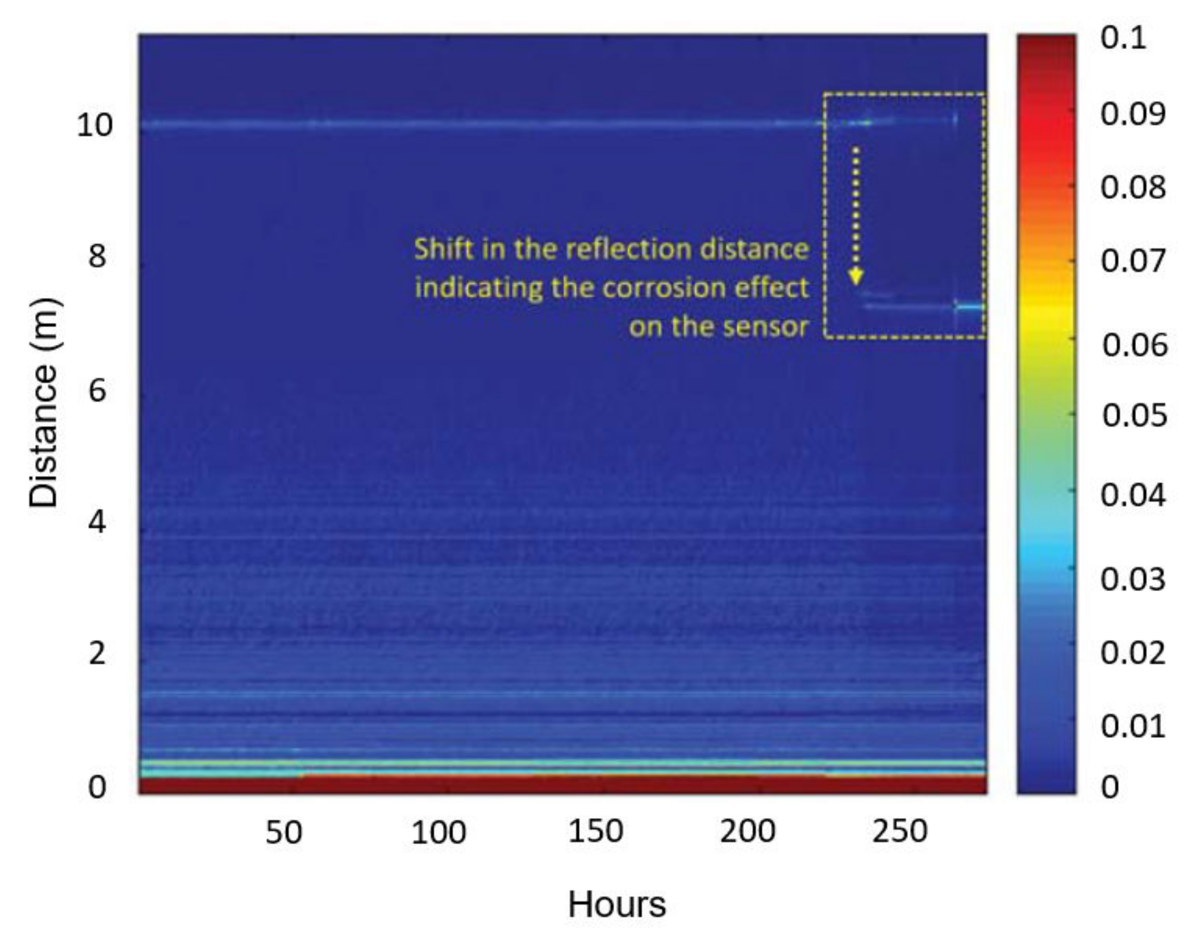
3.7. Water Sensing Technology

In the past few decades, optical fibre has been used to sense humidity within the insulation and detect the potential occurrence of CUI [96]. Thomas et al. [97] designed and employed a distributed fibreoptic sensor system for the continuous inspection of insulation water uptake. The sensor system consisted of two cables—one for humidity measurement and the other cable functionalised as a temperature reference. Two cables were closely wired and fixed at the 6 o’clock position of the pipes. The insulation material used in the study was aerogel insulation. The working mechanism of the specified sensor system was based on Rayleigh scattering. Optical fibre cable that is coated with a hygroscopic coating material is sensitive to variation sourced from ambient moisture content. Extra strain will be generated and loaded on optical fibres when environmental humidity increases, which instantly leads to a pathway shift of the travelling lights from their central location. This technology was reported to have an accurate sensitivity in regard to moisture concentration with a detection limit down to 10 mL per meter.
A drain plug is a water indicator that can be installed at the bottom location of a pipe to sense water leaching from the insulation. Water flows towards the 6′oclock position of the pipes due to gravity, and accumulates within the drain holder, triggering its popping to indicate the presence of water.
In 2017, CorrosionRadar Ltd. [98] developed a patented sensor to detect the presence of moisture within the insulation and the onset of CUI. The systems combine wave reflection time-of-flight technology and industrial Internet of Things (IIoT) application to locate and monitor corrosion under insulation. The sensor wire is layered with a thin film of sacrificial material that tends to corrode in the presence of water. When sacrificial material corrodes, the electromagnetic wave that travels through the wire is reflected and detected remotely. In one of the case studies, corrosion under insulation was detected on insulated equipment after 230 h at a location 7 m away from the wire’s original installation spot. The spectrogram of the reflected signals, as shown in Figure 11, indicates the CUI initiation location.

3.8. CUI Prediction Modelling

Modelling has been employed to predict CUI. The implementation of an appropriate mathematical model can be used to estimate the onset of corrosion and the rate of corrosion propagation. Modelling contributes information in asset management and strategic decision making. The input data are usually collected and retrieved from either field testing or simulated testing in a lab environment. In such a case, the quantity and quality of input data assets play a pivotal role in the performance of a model.
Burhani et al. [99] investigated the effect of input data on the model performance and corrosion prediction accuracy. In one case study, an artificial neural network was used to analyse combined data collected from lab-based experimental testing (as per ASTM G189-07) and field testing. The applied neural network had a three-layer configuration. There are two input nodes in the first layer, one input node in the second layer that collects parameters such as piping age and operating temperature, and one output node in the third layer. Preliminary results indicate a difference in the resultant values of CUI rate, from experimental and field data, respectively. The rate of CUI, based on a prediction of 20 years’ piping operating time, was noted to be significantly lower when employing the in-lab experimental database as input data sources compared with employing data sourced from filed testings. It was reported from the case study that prediction accuracy was enhanced when using combined data sources from lab testing and field testing. Other commonly used models proposed by researchers include logistic regression [100], Bayesian networks [101], and hygrothermal models [102], etc. The details of each model have been thoroughly reviewed by Hou et al. [103].

3.9. Recently Patented CUI Detection Techniques

3.9.1. Thermography and Machine Learning to Detect CUI

A patent written by Amer et al. [104] described a CUI detection method using an automated system that combined the infrared radiography technique and machine learning application. A two-step machine learning system was used to achieve high detection accuracy. The first machine learning system filtered thermographs captured from the infrared camera, and the second machine learning system was employed to analyse thermal images. Input data included thermographs, information on material structure, ambient temperature, etc. The other patent delivered by Amer et al. [69] developed an innovative approach using an unmanned vehicle (drone) integrated with an aerial infrared detector and pulsed eddy current sensor to monitor CUI remotely.

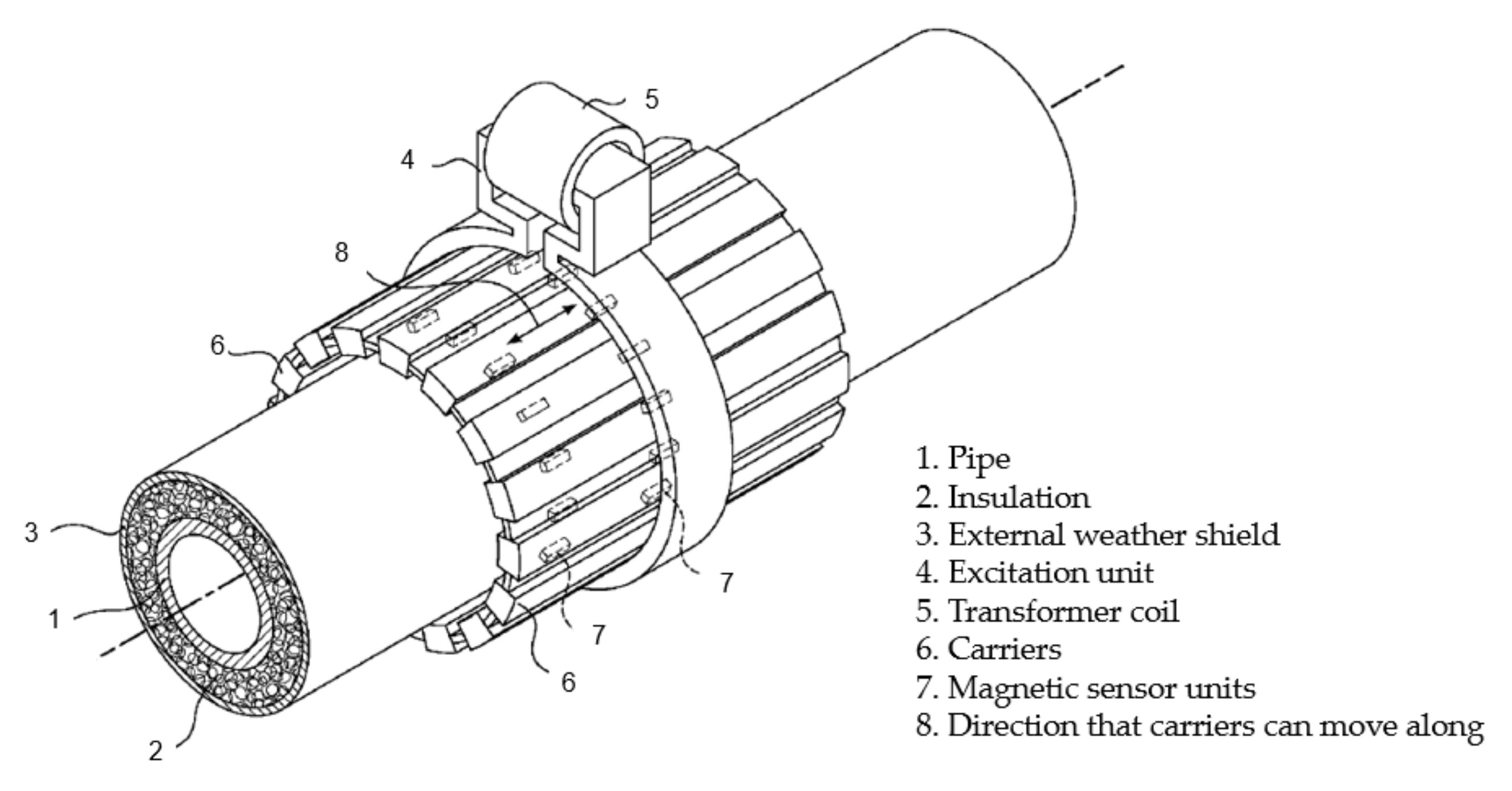
3.9.2. Excitation Methodology to Detect CUI

Bondurant et al. introduced equipment applying an electrically conductive excitation unit to detect CUI. The excitation unit comprises an electrical excitation coil and a power source, as shown in Figure 12. The power source generates an alternating current and CUI can be detected from the changes in magnetic flux that are created by the alternating current [105].
In summary, the advantages and limitations of each CUI monitoring technique are listed in Table 2. All the above-mentioned CUI detection techniques shall be selected and used depending on varying testing scenarios. Practically, through the combined application of different detection methodologies, the detection accuracy can be largely improved.

4. CUI Mitigation

4.1. Coatings

The application of protective coating material is considered a highly effective method to mitigate CUI. Coating isolates metallic substrate and acts as the last barrier to prevent the rapid corrosion of the metallic substrate [6]. A protective coating layer can protect steel substrate from the infiltration of oxygen, moisture, and corrosive electrolytes, hence, retarding the electrochemical reactions that occur on the metallic substrates [96,97,98]. Nevertheless, a poorly applied coating can be detrimental, as coating defects retain contaminants, exacerbating CUI [1]. An example of CUI coating is thermal spray aluminium (TSA), as shown in Figure 13, a type of metallic coating that can be applied on process equipment, storage vessels, and piping. TSA has a long service life of more than 25 years and is able to provide good adhesion and cathodic protection to the exposed steel substrates [50,106]. The integrity of TSA can be affected by multiple factors with recorded premature coating failure (e.g., cracking, blistering, and detachment) reported due to poor surface preparation and coating application [51,106,107]. TSA coating can be applied through a combustion wire-fed system or the twin wire arc method, with both processes involving flame generation. Therefore, partial processing unit shutdown is required when TSA is used for repair, to avoid potential ignition risk.
Organic coatings are also commonly used. NACE SP0198 recommended epoxy phenolic (aromatic organic compounds with the formula C6H5OH), epoxy novolac (polymers derived from phenols and formaldehyde), and high-build epoxy as typical protective coating systems for austenitic and duplex stainless steels under thermal insulation [6]. Epoxy phenolic coatings have outstanding performance in terms of long-term protection against CUI at a temperature range from 3 to 230 °C. Coatings may undergo a certain level of degradation when operating temperatures are outside of the before-mentioned range [9]. Polysiloxane (polymers comprising synthetic compounds of repeating siloxane units) or so-called high-build silicones have excellent temperature tolerance and UV resistance. Reynolds et al. [108] introduced a polysiloxane thermal coating for CUI mitigation. Nevertheless, any coating will degrade over time, especially when insulation is wet, and moisture is retained within the annular space, which is a natural reservoir for water retention. Water or corrosive electrolyte can further deteriorate metal substrate if any defects in coating are left unattended either during the application or after exposure. The average service life of the protective coating is 5–13 years and most coating systems in old insulated equipment are now near the end of their service life, requiring repair or replacement [51].
Coating applications should meet the minimum industrial requirement in regard to substrate surface preparation, specified coating wet film thickness, and dry film thickness, which are essential to a coating’s final performance. Coating will not provide its intended service life if it is applied over salt/corrosive medium due to contamination (lack of surface preparation). The adhesion strength between coating and substrate will be largely reduced if substrate surface preparation is inappropriate. Coating applied on pipework that is processed under elevated temperatures and intermittent duty can introduce a complex degradation process, as both moisture and thermally induced stress can be another contributing factor. In a hot oil line case study, CUI was found in the form of chained pitting, as shown in Figure 14. The coating used on the inlet line was noticed to have been heavily degraded, with clear flaking and rusting observed. It was inferred that the applied coating had a temperature tolerance below the piping operating temperature at 240 °C [109]. Ingressed saltwater was considered to be another contributing factor, especially when chlorides can concentrate when electrolytes evaporate at high temperatures. A subsequent solution to the problem was to replace the protective coating system with a heat-resistant cold spray aluminium coating.
Currently, there is no standardised testing protocol for CUI coating evaluation [3]. ISO19277 provides a reference methodology to determine corrosion performance under thermal insulation. A variety of test setups were used by researchers to evaluate coating performance in a CUI scenario. Marie Halliday et al. [110] employed a vertical pipe to study coating performance under insulation. The insulated pipe was placed on a hot plate and coating performance under insulation was examined along the overall length of the pipe at a temperature gradient. Dik Betzig [111] developed a test apparatus to investigate coating under insulation at elevated temperatures using a square-shaped pipe. Kristian Haraldsen implemented a steam heating system in conjunction with a test loop to evaluate three types of coatings at 140 °C. The results show that phenolic epoxy coating had the best performance among all the coatings tested [47]. Yang et al. [3] introduced a new coating evaluation protocol to assess coating integrity by examining and rating the form of degradation—blistering, cracking, and rusting appearance—to compare coating performance. A cyclic test plan that combines wet and dry, heating and cooling, and periodic exposure to the corrosive electrolyte (e.g., sodium chloride and ammonium sulfate solution to simulate inland industrial environment), is recommended for the best simulation of the synergistic interaction impact from the field environmental factors [112]. ASTM D5894 [113], proposed ISO 20340 [114], and modified NACE TM-0184 [115] are commonly used standards to evaluate painted metal under cyclic weathering conditions. However, these standards are not specific to CUI and do not replicate the key CUI process. Currently, there is still no agreement on standardised test apparatus and cyclic conditions. Design and application towards a standardised coating evaluation testing methodology in the case of corrosion under insulation is a future task.

4.2. Risk-Based Inspection

Risk-based inspection (RBI), an optimal decision-making methodology, has been widely incorporated into CUI evaluation, offering informative recommendations for CUI mitigation [116]. The technique collects and analyses historical data, related to the operational and structural conditions of insulated equipment, to determine CUI risk level. The accuracy of the input data set is critical in an RBI analysis. Usually, a complete RBI cycle for CUI evaluation includes four major components: quality prioritisation set-up, data validation, information on the insulation type, and RBI assessment [1]. RBI-based inspection can be carried out in either a quantitative or qualitative manner. Quantitative RBI employs a numeric model for data input and output to estimate the overall impact of corrosion risk. Qualitative RBI evaluates each inspection step and offers respective and descriptive ranking [117,118]. The validation of input data is critical because poorly recorded historical data can lead to a deviation/error of corrosion evaluation and prediction [57]. Data that require validation include wall thickness loss, protective coating information, and insulation wetting frequency [117]. Erickson et al. [119] employed the Weibull distribution as a statistical means to predict the cumulative damage of the insulated piping equipment over time. However, the field application of RBI requires immense resources of information input, and the output accuracy is also largely influenced by the procedures of data collection. The overall procedure is costly and may not be suitable for CUI inspection in a small-scale plant.

4.3. Other Solutions for CUI Mitigation

Pojtanabuntoeng et al. [120] elucidated the efficacy of drilling holes through the external jacketing of an insulated pipe at the top and bottom locations, to allow trapped water to evaporate faster. CUI was found to be significantly reduced when hydrophobic insulation was used and drain holes were employed. Future studies on how those drain holes can be retrofitted and the resultant improvement efficiency on enhancing CUI protection are still of interest.
A strategy implementing a zinc rod as sacrificial cathodic protection (CP) for CUI remediation has been trialled and validated as a proof-of-concept for CUI mitigation [121]. The results reveal that sacrificial zinc can be used to mitigate CUI when moisture content within the insulation is over 25 vol%. An increasing level of ion migration was found when moisture content within the insulation was sufficient. Experimental results reveal a 63% CP efficiency was achieved when zinc was in direct contact with mild steel substrate and insulation was fully saturated (Figure 15). Zinc could therefore be potentially implemented at the six o’clock location of an insulated pipe where moisture is prone to accumulate. However, the suitability of sacrificial protection using zinc for high-temperature applications is not recommended because zinc will reverse its polarity, from anode to cathode, at high temperatures. Consequently, the metallic substrate will corrode more severely.

5. Conclusions

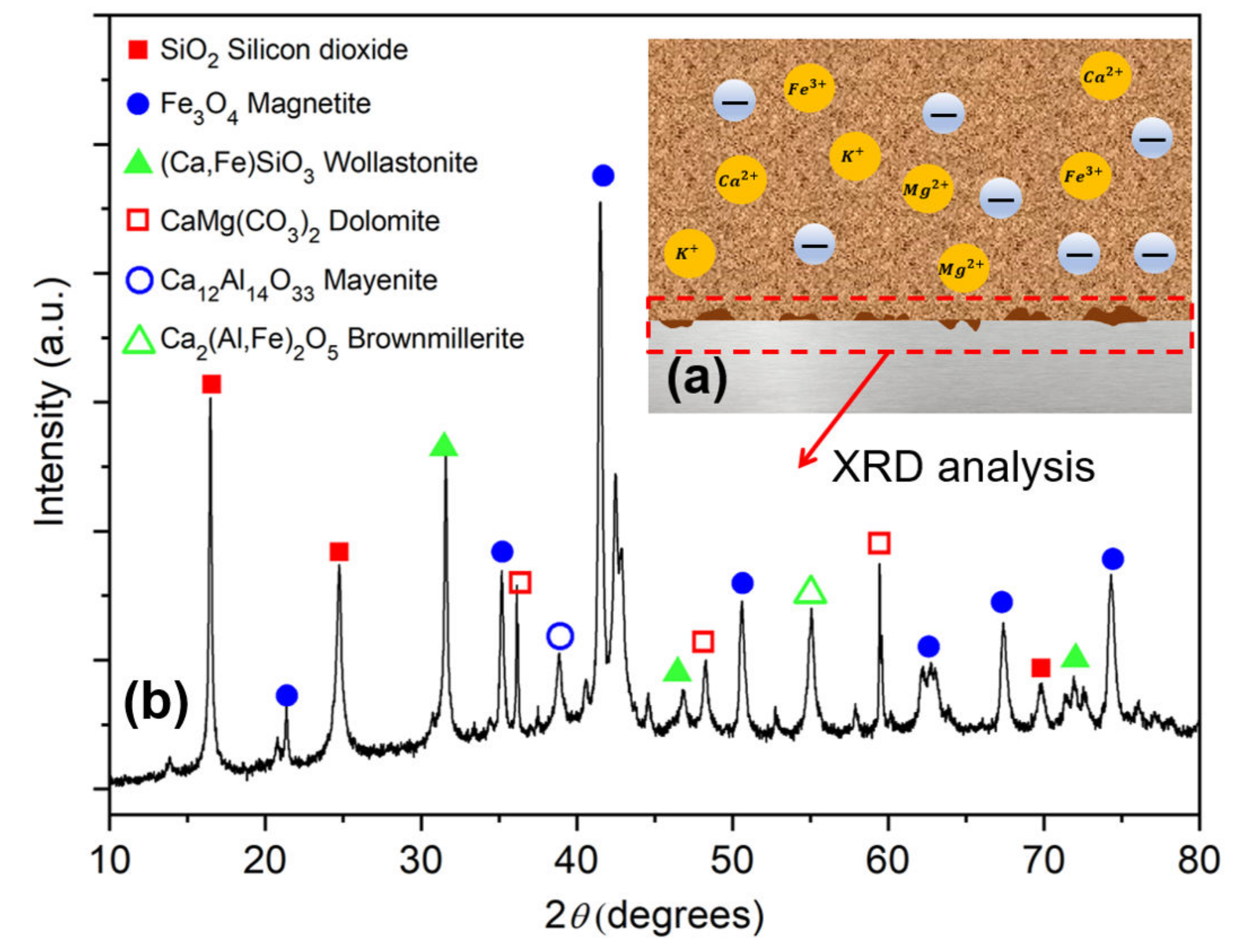
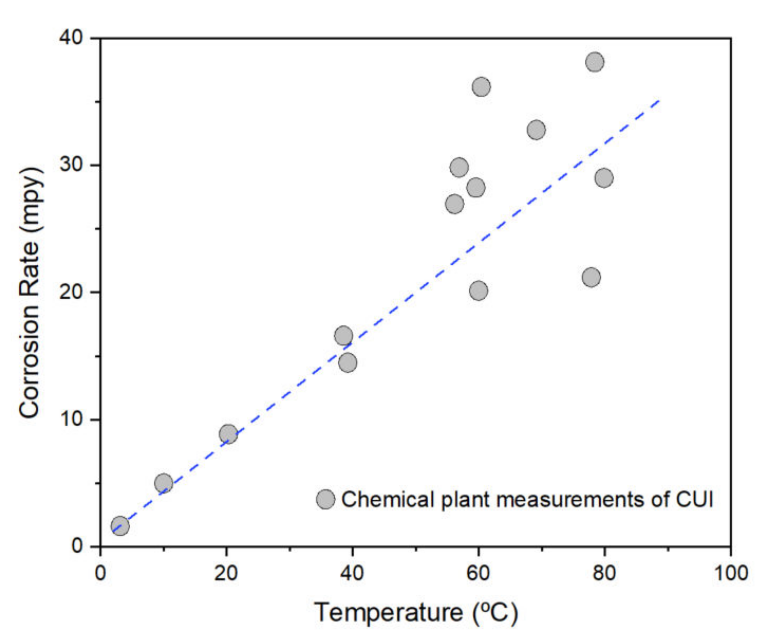
  • Corrosion under insulation is caused by the penetration of moisture/water through jacketing and insulation, causing final direct contact with the underlying metallic substrate. A variety of environmental factors can influence the rate of CUI, which include operating temperature, solution pH, and contaminants, etc.
  • At present, the only method that ensures the effective screening of CUI is to remove external jacketing/cladding and inspect piping conditions visually. NDT is an economical and efficient corrosion detection technique that can be employed without damaging pristine materials. Each type of NDT technique has its own advantages and drawbacks. Radiography and ultrasonic techniques are widely used to detect CUI. A recent trend is the use of an electrochemical probe to detect local corrosion, and the employment of modelling to predict CUI. Machine learning has been developed to collect data and train the model for better accuracy.
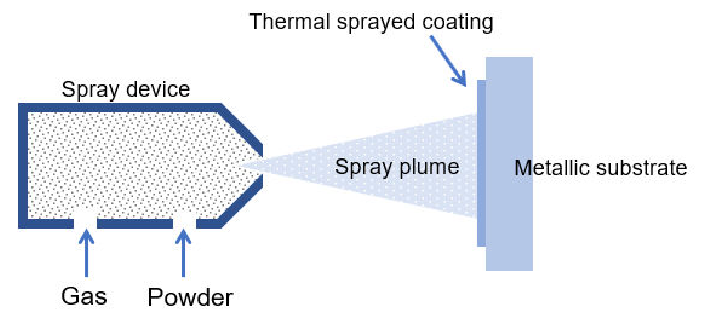
  • Protective coating, either metallic or organic, is the last barrier to prevent and inhibit the metallic piping substrate from external corrosion attacks. Thermal sprayed aluminium and epoxy-phenolics are commonly used in oil and gas piping due to their versatile temperature tolerance and outstanding service life. Recently, new generations of thermal insulation coating (i.e., polysiloxane-based) are recommended as advanced coating systems to alleviate CUI effectively. Any coatings will degrade over time, and therefore, coating materials with exceptional resistance to corrosion, chemical, and weathering processes are promptly required.
  • Risk-based inspection is a widely sought-after methodology for CUI prediction and mitigation; however, in sectors where there are severe consequences for corrosion failure, RBI may not be sufficiently reliable.
  • Drain holes can be implemented at the bottom of a pipe to release water retained within the insulation and hence reduce CUI.

Author Contributions

Q.C. undertook the detailed review of the research papers and drafted the manuscript. T.P., M.E. and N.B. provided thorough proofreading and editing of the manuscript. S.T. and M.B. provided review of the manuscript. A.A. undertook the review of the CUI monitoring section. All authors have read and agreed to the published version of the manuscript.

Funding

This research received no external funding.

Data Availability Statement

Not applicable.

Acknowledgments

The support from Woodside Energy and Curtin Corrosion Centre is gratefully acknowledged. Q.C. thanks Kate Narin, Mariano Iannuzzi, and Peter Bock for proofreading and Yu (Louis) Long for image editing. M.E. also thanks the Swedish Research Council and Helge Ax: son Johnsons Stiftelse (Sweden) for the support. A.A. thanks the Research & Development Center, Oil and Gas Network Integrity Division, Advanced Sensors Team of Saudi Aramco for their support in publishing this paper.

Conflicts of Interest

The authors declare no conflict of interests.

References

  1. Winnik, S. Corrosion Under Insulation (CUI) Guidelines, 2nd ed.; Elsevier: Cambridge, UK, 2015. [Google Scholar]
  2. Delahunt, J.F. Corrosion Under Thermal Insulation and Fireproofing—An Overview. In Proceedings of the Corrosion 2003, San Diego, CA, USA, 16–20 March 2003. [Google Scholar]
  3. Yang, Y.; Bodington, A.B.; Chang, B.T.A. Evaluation of protective coatings to mitigate corrosion under insulation. In Proceedings of the Corrosion 2016, Vancouver, BC, Canada, 6–10 March 2016. [Google Scholar]
  4. Hoffman, A. Moisture as a cause of CUI. Corros. Mater. 2017, 42, 46–47. [Google Scholar]
  5. Swift, M. Corrosion under insulation on industrial piping—A holistic approach to insulation system design. In Proceedings of the Corrosion 2019, Nashville, TN, USA, 24–28 March 2019. [Google Scholar]
  6. NACE Standard SP0198; Control of Corrosion under Thermal Insulation and Fire Proofing Materials—A Systems Approach. NACE: Houston, TX, USA, 2017.
  7. Koch, G.; Varney, J.; Thompson, N.; Moghissi, O. International measures of prevention, application, and economics of corrosion technologies study. NACE Int. Impact Rep. 2016, 216, 2–3. [Google Scholar]
  8. Anderson, S.A. Out of sight, out of mind. Hydrocarb. Eng. 2010, 15, 64–69. [Google Scholar]
  9. Wilds, N. Corrosion under insulation. Trends Oil Gas Corros. Res. Technol. Prod. Transm. 2017, 17, 409–429. [Google Scholar]
  10. Abayarathna, D.; Ashbaugh, W.G.; Kane, R.D.; McGowan, N.; Heimann, B. Measurement of corrosion under insulation and effectiveness of protective coatings. In Proceedings of the Corrosion 97, New Orleans, LA, USA, 9–14 March 1997. [Google Scholar]
  11. NACE Standard RP0198; The Control of Corrosion Under Thermal Insulation and Fireproofing Materials—A Systems Approach. NACE: Houston, TX, USA, 1998.
  12. NACE Standard RP0198; The Control of Corrosion Under Thermal Insulation and Fireproofing Materials—A Systems Approach. NACE: Houston, TX, USA, 2004.
  13. NACE Standard RP0198; The Control of Corrosion Under Thermal Insulation and Fireproofing Materials—A Systems Approach. NACE: Houston, TX, USA, 2010.
  14. Geary, W.; Parrott, R. Two corrosion under insulation case studies. Loss Prev. Bull. 2016, 250, 2–6. [Google Scholar]
  15. Chao, Q.; Cruz, V.; Thomas, S.; Birbilis, N.; Collins, P.; Taylor, A.; Hodgson, P.D.; Fabijanic, D. On the enhanced corrosion resistance of a selective laser melted austenitic stainless steel. Scr. Mater. 2017, 141, 94–98. [Google Scholar] [CrossRef]
  16. Sedriks, A.J. Corrosion of Stainless Steel, 2nd ed.; Wiley-Interscience: New York, NY, USA, 1996. [Google Scholar]
  17. Jiang, D.; Gao, X.; Zhu, Y.; Hutchinson, C.; Huang, A. In-situ duplex structure formation and high tensile strength of super duplex stainless steel produced by directed laser deposition. Mater. Sci. Eng. A 2021, 833, 142557. [Google Scholar] [CrossRef]
  18. Olsson, J.; Snis, M. Duplex—A new generation of stainless steels for desalination plants. Desalination 2007, 205, 104–113. [Google Scholar] [CrossRef]
  19. Eltai, E.; Alkhalifa, K.; Al-Rayashi, A.; Mahdi, E.; Hamouda, A.M.S. Investigating the corrosion under insulation (CUI) on steel pipe exposed to Arabian gulf sea water drops. Key Eng. Mater. 2016, 689, 148–153. [Google Scholar] [CrossRef]
  20. Caines, S.; Khan, F.; Shirokoff, J.; Qiu, W. Experimental design to study corrosion under insulation in harsh marine environments. J. Loss Prev. Process Ind. 2015, 33, 39–51. [Google Scholar] [CrossRef]
  21. Liss, V.M. Preventing corrosion under insulation. Natl. Board Boil. Press. Vessel Insp. 1998, 94, 97–98. [Google Scholar]
  22. Fruge, D.; Bishop, K. Corrosion under Insulation. In Proceedings of the 20th Annual Ethylene Producers Conference, New Orleans, LA, USA, 7–10 April 2008. [Google Scholar]
  23. Geary, W. Analysis of a corrosion under insulation failure in a carbon steel refinery hydrocarbon line. Case Stud. Eng. Fail. Anal. 2013, 1, 249–256. [Google Scholar] [CrossRef] [Green Version]
  24. API RP 583; Corrosion Under Insulation and Fireproofing. American Petroleum Institute: Washington, DC, USA, 2021.
  25. Hatch, J.E. Aluminum: Properties and Physical Metallurgy; ASM International: Novelty, OH, USA, 1984. [Google Scholar]
  26. Davis, J.R. Aluminum and Aluminum Alloys; ASM International: Novelty, OH, USA, 1993. [Google Scholar]
  27. Ashkenazi, D. How aluminum changed the world: A metallurgical revolution through technological and cultural perspectives. Technol. Forecast. Soc. Chang. 2019, 143, 101–113. [Google Scholar] [CrossRef]
  28. Mohammed, A.A.; Manalo, A.C.; Ferdous, W.; Zhuge, Y.; Vijay, P.V.; Alkinani, A.Q.; Fam, A. State-of-the-art of prefabricated FRP composite jackets for structural repair. Eng. Sci. Technol. Int. J. 2020, 23, 1244–1258. [Google Scholar] [CrossRef]
  29. Mahdi, E.; Eltai, E. Development of cost-effective composite repair system for oil/gas pipelines. Compos. Struct. 2018, 202, 802–806. [Google Scholar] [CrossRef]
  30. Vrána, T. Impact of Moisture on Long Term Performance of Insulating Products Based on Stone Wool. Licentiate Thesis, KTH Royal Institute of Technology, Stockholm, Sweden, 2007. [Google Scholar]
  31. Denniel, S.; Blair, C. Aerogel insulation for deepwater reelable pipe-in-pipe. In Proceedings of the Offshore Technology Conference, Houston, TX, USA, 3–6 May 2004. [Google Scholar]
  32. ASTM C1696; Standard Guide for Industrial Thermal Insulation Systems. ASTM International: West Conshohocken, PA, USA, 2020.
  33. Turner, W.C.; Malloy, J.F. Handbook of Thermal Insulation Design Economics for Pipes and Equipment; Krieger Pub Co.: Malabar, FL, USA, 1980. [Google Scholar]
  34. Kelly, M. Insulation—Terms, Definitions & Formula. Trade Ind. Insul. 2014, 4, 3–12. [Google Scholar]
  35. Wang, S.; Qiu, J. Enhancing thermal conductivity of glass fiber/polymer composites through carbon nanotubes incorporation. Compos. Part B Eng. 2010, 41, 533–536. [Google Scholar] [CrossRef]
  36. Cellular Glass—Foam Glass—Thermal Insulation. 2020. Available online: https://www.nuclear-power.net/nuclear-engineering/heat-transfer/heat-losses/insulation-materials/foam-glass-cellular-glass/ (accessed on 24 December 2021).
  37. Thermal Conductivity of Polyurethane Foam. 2020. Available online: https://www.nuclear-power.net/nuclear-engineering/heat-transfer/heat-losses/insulation-materials/thermal-conductivity-of-polyurethane-foam/ (accessed on 23 December 2021).
  38. Insulating Materials Thermal Properties. 2020. Available online: https://www.engineersedge.com/heat_transfer/insulating_materials_13858.htm (accessed on 24 December 2021).
  39. Herrmann, G.; Iden, R.; Mielke, M.; Teich, F.; Ziegler, B. On the way to commercial production of silica aerogel. J. Non. Cryst. Solids 1995, 186, 380–387. [Google Scholar] [CrossRef]
  40. Nash, A. Permeability of Common Building Material to Water Vapor. 2017. Available online: http://cespubs.uaf.edu/index.php/download_file/1012/ (accessed on 6 January 2022).
  41. ASTM C1511; Standard Test Method for Determining the Water Retention (Repellency) Characteristics of Fibrous Glass Insulation (Aircraft Type). ASTM International: Houston, TX, USA, 2015.
  42. Williams, O.E.J. The influence of insulation materials on corrosion under insulation. In Proceedings of the 2010 NACE Northern Area Western Conference: Going for Gold in Corrosion Prevention, Calgary, AB, Canada, 15–18 February 2010. [Google Scholar]
  43. Fesmire, J.E.; Ancipink, J.B.; Swanger, A.M.; White, S.; Yarbrough, D. Thermal conductivity of aerogel blanket insulation under cryogenic-vacuum conditions in different gas environments. IOP Conf. Ser. Mater. Sci. Eng. 2017, 278, 1–9. [Google Scholar] [CrossRef]
  44. Cohen, E.; Glicksman, L. Thermal Properties of Silica Aerogel Formula. J. Heat Transfer. 2015, 137, 081601. [Google Scholar] [CrossRef] [Green Version]
  45. KISTLER, S.S. Coherent expanded aerogels and jellies. Nature 1931, 127, 741. [Google Scholar] [CrossRef]
  46. Miros, A.; Psiuk, B.; Szpikowska-Sroka, B. Aerogel insulation materials for industrial installation: Properties and structure of new factory-made products. J. Sol-Gel Sci. Technol. 2017, 84, 496–506. [Google Scholar] [CrossRef] [Green Version]
  47. Haraldsen, K. Corrosion under insulation—Testing of protective systems at high temperatures. In Proceedings of the Corrosion 2010, San Antonio, TX, USA, 14–18 March 2010. [Google Scholar]
  48. ASTM C795-08; Standard Specification for Thermal Insulation for Use in Contact with Austenitic Stainless Steel. ASTM International: West Conshohocken, PA, USA, 2013.
  49. Cao, Q.; Esmaily, M.; Liu, R.L.; Birbilis, N.; Thomas, S. Corrosion of mild steel under insulation—The effect of dissolved metal ions. Corros. Eng. Sci. Technol. 2020, 55, 322–330. [Google Scholar] [CrossRef]
  50. Javaherdashti, R. Corrosion under insulation (CUI): A review of essential knowledge and practice. J. Mater. Sci. Surf. Eng. 2014, 1, 36–43. [Google Scholar]
  51. Bock, P. Service life, reliability and reparability of systems for preventing corrosion under insulation. In Proceedings of the Corrosion 2012, Salt Lake City, UT, USA, 11–15 March 2012. [Google Scholar]
  52. Mohsin, K.M.; Mokhtar, A.A.; Tse, P.W. A fuzzy logic method: Predicting corrosion under insulation of piping systems with modelling of CUI 3D surfaces. Int. J. Press. Vessel. Pip. 2019, 175, 103929. [Google Scholar] [CrossRef]
  53. Dey, P. A risk-based model for inspection and maintenance of cross-country petroleum pipeline. J. Qual. Maint. Eng. 2001, 7, 25–43. [Google Scholar] [CrossRef]
  54. Mitchell, M.J. Corrosion under insulation—New approaches to coating and insulation materials. In Proceedings of the Corrosion 2003, San Diego, CA, USA, 16–20 March 2003. [Google Scholar]
  55. ASTM G189; Standard Guide for Laboratory Simulation of Corrosion Under Insulation. ASTM International: Houston, TX, USA, 2013.
  56. Pojtanabuntoeng, T.; Machuca, L.L.; Salasi, M.; Kinsella, B.; Cooper, M. Influence of drain holes in jacketing on corrosion under thermal insulation. Corrosion 2015, 71, 1511–1520. [Google Scholar] [CrossRef]
  57. Matsuda, H.; Ichi Sakai, J. Application of effective maintenance for CUI (Corrosion Under Insulation) of pipes in chemical plants. In Proceedings of the Corrosion 2015, Dallas, TX, USA, 15–19 March 2015. [Google Scholar]
  58. Pechacek, R.W. NDT inspection of insulated vessels and piping for interior corrosion and corrosion under insulation. Mater. Perform. 2004, 43, 28–32. [Google Scholar]
  59. Prawoto, Y.; Ibrahim, K.; Wan Nik, W.B. Effect of pH and chloride concentration on the corrosion of duplex stainless steel. Arab. J. Sci. Eng. 2009, 34, 116–127. [Google Scholar]
  60. Dillmann, P.; Mazaudier, F.; Hœrlé, S. Advances in understanding atmospheric corrosion of iron. I. Rust characterisation of ancient ferrous artefacts exposed to indoor atmospheric corrosion. Corros. Sci. 2004, 46, 1401–1429. [Google Scholar]
  61. Abdel-Karim, R.; Nabil, M.; Reda, Y.; El-Raghy, S. Corrosion Characteristics of ASTM A106 Grade B Carbon Steel Pipelines Exposed to Sodium Sulfate Solutions; ASTM International: Houston, TX, USA, 2018; Volume 7. [Google Scholar]
  62. Mueller, A.P. Corrosion-Inhibiting Thermal Insulation for Stainless Steel. U.S. Patent 3,639,276, 1 February 1972. [Google Scholar]
  63. Armstrong, R.D.; Zhou, S. The corrosion inhibition of iron by silicate related materials. Corros. Sci. 1988, 28, 1177–1181. [Google Scholar] [CrossRef]
  64. Amer, A.; Cunningham, V.; Alshehri, A.; Al-Taie, I. Inspection challenges for detecting corrosion under insulation (CUI) in the oil and gas industry. In Proceedings of the 17th Middle East Corrosion Conference and Exhibition (MECC), Al Khobar, Saudi Arabia, 30 September–3 October 2018. [Google Scholar]
  65. Cadelano, G.; Bortolin, A.; Ferrarini, G.; Agnellini, B.M.; Giantin, D.; Zonta, P.P.; Bison, P. Corrosion detection in pipelines using infrared thermography: Experiments and data processing methods. J. Nondestruct. Eval. 2016, 35, 1–11. [Google Scholar] [CrossRef]
  66. Burleigh, D.; Sanders, H. Infrared evaluation of insulated pipelines to detect water that could cause corrosion under insulation (CUI). Int. Soc. Opt. Eng. 2012, 8354, 21. [Google Scholar]
  67. Maldague, X. Introduction to NDT by active infrared thermography. Mater. Eval. 2002, 60, 1060–1073. [Google Scholar]
  68. Subramainam, B.; Lahiri, B.B.; Saravanan, T.; Philip, J.; Jayakumar, T. Infrared thermography for condition monitoring—A review. Infrared Phys. Technol. 2013, 60, 35–55. [Google Scholar]
  69. Amer, A.; Shehri, A. Two-Stage Corrosion under Insulation Detection Methodology and Modular Vehicle with Dual Locomotion Sensory Systems. U.S. Patent 10,139,372, 27 November 2019. [Google Scholar]
  70. Higgins, J. Corrosion under Insulation Detection Methods and Inspection; NACE International: Orlando, FL, USA, 2013. [Google Scholar]
  71. Callister, W.C. Profile radiography by gamma rays. Non-Destr. Test. 1972, 5, 214–219. [Google Scholar] [CrossRef]
  72. Pechacek, R.W. Advanced NDE methods of inspecting insulated vessels and piping for ID corrosion and corrosion under insulation (CUI). In Proceedings of the Corrosion 2003, San Diego, CA, USA, 16–20 March 2003. [Google Scholar]
  73. Rowlands, J.A. The physics of computed radiography. Phys. Med. Biol. 2002, 47, 123–166. [Google Scholar] [CrossRef]
  74. Samei, E.; Seibert, J.A.; Willis, C.E.; Flynn, M.J.; Mah, E.; Junck, K.L. Performance evaluation of computed radiography systems. Med. Phys. 2001, 28, 361–371. [Google Scholar] [CrossRef]
  75. Lee, D.L.Y.; Cheung, L.K.; Jeromin, L.S. New digital detector for projection radiography. In Proceedings of the SPIE 2432, Medical Imaging 1995: Physics of Medical Imaging, San Diego, CA, USA, 8 May 1995; pp. 237–249. [Google Scholar]
  76. Bray, A.V.; Corley, C.J.; Fischer, R.B.; Rose, J.L.; Quarry, M.J. Development of guided wave ultrasonic techniques for detection of corrosion under insulation in metal pipe. In Proceedings of the 1998 ASME Energy Sources Technology Conference, Houston, TX, USA, 2–4 February 1998; pp. 1–3. [Google Scholar]
  77. Jones, R.; Simonetti, F.; Lowe, M.; Bradley, I. Use of microwaves for the detection of corrosion under insulation: A sensitivity study. AIP Conf. Proc. 2011, 1335, 1714–1721. [Google Scholar]
  78. Krautkrämer, J.; Krautkrämer, H. Ultrasonic testing by determination of material properties. In Ultrasonic Testing of Materials; Springer: Berlin/Heidelberg, Germany, 1990; pp. 528–550. [Google Scholar]
  79. Lohr, K.R.; Rose, J.L. Ultrasonic guided wave and acoustic impact methods for pipe fouling detection. J. Food Eng. 2003, 56, 315–324. [Google Scholar] [CrossRef]
  80. Zhu, W.; Rose, J.L.; Barshinger, J.N.; Agarwala, V.S. Ultrasonic guided wave NDT for hidden corrosion detection. J. Res. Nondestruct. Eval. 1998, 10, 205–225. [Google Scholar] [CrossRef]
  81. Singh, R. Ultrasonic testing. Appl. Weld. Eng. 2012, 6, 293–304. [Google Scholar]
  82. Demers-Carpentier, V. Corrosion Under Insulation: The 7 Inspection Methods You Must Know About. 3 April 2016. Available online: https://blog.eddyfi.com/en/corrosion-under-insulation-the-7-inspection-methods-you-must-know-about/ (accessed on 23 December 2021).
  83. Burke, S.K.; Hugo, G.R.; Harrison, D.J. Transient eddy-current NDE for hidden corrosion in multilayer structures. In Review of Progress in Quantitative Nondestructive Evaluation; Springer: Boston, MA, USA, 1998; pp. 307–314. [Google Scholar]
  84. Sophian, A.; Fan, M. Pulsed eddy current non-destructive testing and evaluation: A review. Chinese J. Mech. Eng. 2017, 30, 1474. [Google Scholar] [CrossRef]
  85. Cheng, W.; Komura, I. Pulsed eddy current testing of a carbon steel pipe’s wall-thinning through insulation and cladding. J. Nondestruct. Eval. 2012, 31, 215–224. [Google Scholar]
  86. Brett, C.R.; Raad, J.A. Validation of a pulsed eddy current system for measuring wall thinning through insulation. Proc. SPIE. 1996, 2947, 211–222. [Google Scholar]
  87. Angani, C.S.; Park, D.G.; Kim, C.G.; Leela, P.; Kollu, P.; Cheong, Y.M. The pulsed eddy current differential probe to detect a thickness variation in an insulated stainless steel. J. Nondestruct. Eval. 2010, 29, 248–252. [Google Scholar] [CrossRef]
  88. Lenka, S. Corrosion under insulation (CUI)-inspection technique and prevention. Non-Destr. Eval. 2017, 6, 97–103. [Google Scholar]
  89. Hart, T. Neutron Backscatter versus Gamma Transmission Analysis for Coke Drum Applications. Available online: https://tools.thermofisher.com/content/sfs/brochures/EPM-ANCoker-0215.pdf (accessed on 20 December 2021).
  90. Eltai, E.O.; Musharavati, F.; Mahdi, E. Severity of corrosion under insulation (CUI) to structures and strategies to detect it. Corros. Rev. 2018, 37, 553–564. [Google Scholar] [CrossRef]
  91. Aung, N.; Wai, W.; Tan, Y.-J. A novel electrochemical method for monitoring corrosion under insulation. Anti-Corros. Methods Mater. 2006, 53, 175–179. [Google Scholar] [CrossRef]
  92. Hladky, K.; Dawson, J.L. The measurement of localized corrosion using electrochemical noise. Corros. Sci. 1981, 21, 317–322. [Google Scholar] [CrossRef]
  93. Kiwilszo, M.; Smulko, J. Pitting corrosion characterization by electrochemical noise measurements on asymmetric electrodes. J. Solid State Electrochem. 2009, 13, 1681–1686. [Google Scholar] [CrossRef]
  94. Hou, Y.; Pojtanabuntoeng, T.; Iannuzzi, M. Use of electrochemical current noise method to monitor carbon steel corrosion under mineral wool insulation. Npj Mater. Degrad. 2020, 4, 39. [Google Scholar] [CrossRef]
  95. Metal Samples Electrochemcial Resistance (ER) Monitoring. 2021. Available online: https://www.alspi.com/erintro.htm (accessed on 20 December 2021).
  96. Alwis, L.; Sun, T.; Grattan, K.T.V. Optical fibre-based sensor technology for humidity and moisture measurement: Review of recent progress. Measurement 2013, 46, 4052–4074. [Google Scholar] [CrossRef]
  97. Thomas, P.J.; Hellevang, J.O. A distributed fibre optic approach for providing early warning of Corrosion Under Insulation (CUI). J. Loss Prev. Process Ind. 2020, 64, 104060. [Google Scholar] [CrossRef]
  98. CorrosionRADAR Ltd. CorrosionRadar-CUI Monitoring System. Materials Performance 2019 Award Nomination. 25 March 2019. Available online: http://resources.nace.org/pdfs/mp-awards/CorrosionRADAR-CUI-Monitoring-System.pdf (accessed on 6 January 2022).
  99. Burhani, N.R.A.; Muhammad, M.; Rosli, N.S. Combined experimental and field data sources in a prediction model for corrosion rate under insulation. Sustainability 2019, 11, 6853. [Google Scholar] [CrossRef] [Green Version]
  100. Burhani, N.R.A.; Muhammad, M.; Mokhtar, A.A.; Ismail, M.C. Application of logistic regression in resolving influential risk factors subject to corrosion under insulation. In Proceedings of the 2016 International Conference on Industrial Engineering and Operations Management, Kuala Lumpur, Malaysia, 8–10 March 2016; pp. 8–10. [Google Scholar]
  101. Kumar, N.K.; Mackenzie, B.; Løken, K.H. Using advanced analytics to identify the most probable locations of corrosion under insulation. In Proceedings of the SPE Offshore Europe Conference and Exhibition, Aberdeen, UK, 3–9 September 2019; pp. 3–9. [Google Scholar]
  102. Venkateswaran, S.P.; Desjarlais, A.O.; Shrestha, S.S.; Bieri, T. Use of hygrothermal models for understanding water transport in corrosion under insulation applications. Paper presented at the Corrosion 2019, Nashville, TN, USA, 24–28 March 2019. [Google Scholar]
  103. Hou, Y.; Pojtanabuntoeng, T. Prediction of corrosion under insulation: A review. Corros. Prev. 2021, 1–11. [Google Scholar]
  104. Amer, A.A.; Shehri, A.; Parrott, B. Thermography Image Processing with Neural Networks to Identify Corrosion under Insulation (CUI). U.S. Patent 10,551,297, 4 February 2020. [Google Scholar]
  105. Bondurant, P.D.; Mactutis, A.; Hunze, A.; Bailey, J. Excitation and Sensing Systems and Methods for Detecting Corrosion under Insulation. U.S. Patent 16/071,892, 31 January 2019. [Google Scholar]
  106. Shrestha, S.; Sturgeon, A. Characteristics and electrochemical corrosion behaviour of thermal sprayed aluminium (TSA) coatings prepared by various wire thermal spray processes. EUROCORR 2005, 1–8. [Google Scholar]
  107. Galedari, S.A.; Mahdavi, A.; Azarmi, F.; Huang, Y.; McDonald, A. A comprehensive review of corrosion resistance of thermally-sprayed and thermally-diffused protective coatings on steel structures. J. Therm. Spray Technol. 2019, 28, 645–677. [Google Scholar] [CrossRef]
  108. Reynolds, J.; Bock, P. Third generation polysiloxane coatings for CUI mitigation. In Proceedings of the Corrosion 2018, Phoenix, AZ, USA, 15–19 April 2018. [Google Scholar]
  109. Ifezue, D.; Tobins, F.H.; Nettikaden, V.C. CUI failure of a hot oil line due to intermittent operations. J. Fail. Anal. Prev. 2014, 14, 13–16. [Google Scholar] [CrossRef] [Green Version]
  110. Halliday, M. Development & testing of new generation high temperature corrosion resistant coatings. In Proceedings of the Corrosion 2005, Houston, TX, USA, 3–7 April 2005. [Google Scholar]
  111. Chang, B.T.A.; Moosavi, A.N. Critical pre-qualification test protocol for external high temperature pipeline coatings. In Proceedings of the Corrosion 2014, San Antonio, TX, USA, 9–13 March 2014. [Google Scholar]
  112. Korobov, Y.; Moore, D.P. Performance testing methods for offshore coatings: Cyclic, EIS and stress. In Proceedings of the Corrosion 2004, New Orleans, LA, USA, 28 March–1 April 2004. [Google Scholar]
  113. ASTM D5894; Standard Practice for Cyclic Salt Fog/UV Exposure of Painted Metal, (Alternating Exposures in a Fog/Dry Cabinet and a UV/Condensation Cabinet). ASTM International: West Conshohocken, PA, USA, 2016.
  114. ISO Standard 12944; Paints and Varnishes—Corrosion Protection of Steel Structures by Protective Paint Systems—Part 9: Protective Paint Systems and Laboratory Performance Test Methods for Offshore and Related Structures. ISO: Geneva, Switzerland, 2018.
  115. NACE TM-0184; Accelerated Test Procedures for Screening Atmospheric Surface Coating Systems for Offshore Platforms and Equipment. NACE International: Houston, TX, USA, 1994.
  116. Wiggen, F.; Justnes, M.; Espeland, S. Risk Based Management of Corrosion Under Insulation. In Proceedings of the SPE International Oilfield Corrosion Conference and Exhibition, Virtual, 16–17 June 2021. [Google Scholar]
  117. Rachman, A.; Ratnayake, R.M.C. Machine learning approach for risk-based inspection screening assessment. Reliab. Eng. Syst. Saf. 2019, 185, 518–532. [Google Scholar] [CrossRef]
  118. Tien, S.-W.; Hwang, W.-T.; Tsai, C.-H. Study of a risk-based piping inspection guideline system. ISA Trans. 2007, 46, 119–126. [Google Scholar] [CrossRef] [PubMed]
  119. Erickson, T.H.; Dash, L.C.; Murali, J.J.; Ayers, R. Predicting the progression of wetness and corrosion under insulation damage in aboveground pipelines. In Proceedings of the Corrosion 2010, San Antonio, TX, USA, 14–18 March 2010. [Google Scholar]
  120. Pojtanabuntoeng, T.; Ehsani, H.; Kinsella, B.; Brameld, M. Comparison of insulation materials and their roles on corrosion under insulation. In Proceedings of the Corrosion 2017, New Orleans, LA, USA, 26–30 March 2017. [Google Scholar]
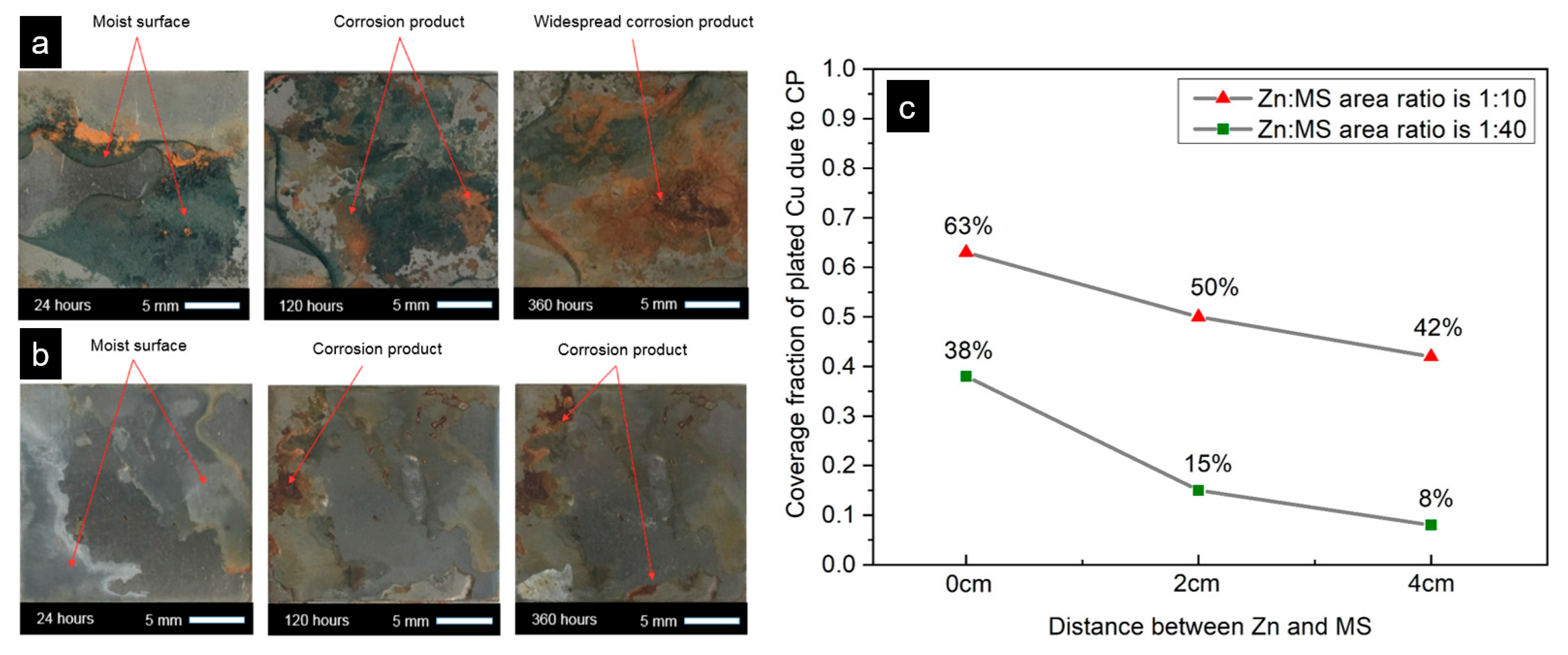
  121. Cao, Q.; Brameld, M.; Birbilis, N.; Thomas, S. On the mitigation of corrosion under insulation (CUI) of mild steel using local cathodic protection. Corrosion 2019, 75, 1541–1551. [Google Scholar] [CrossRef]
Figure 1. Schematic of a typical insulated pipe, which consists of an external cladding/jacketing, insulation material, a protective coating layer, and a steel pipe itself.
Metals 12 00561 g001
Figure 2. Schematic of “non-contact” or “distance-insulation” system [47].
Metals 12 00561 g002
Figure 3. (a) Schematic of metal ions (Fe3+, Ca2+, K+, and Mg2+) that leach out from the insulation and (b) X-ray diffraction characterisation of corrosion products formed upon the steel pipe during its interaction with moist insulation, analysed by Cao et al. [49].
Metals 12 00561 g003
Figure 4. CUI failure in a refinery plant: (a) pipework fracture detail with a huge hole and (b) the installation of walkway bracket touching the pipework. Reprinted with permission from Ref. [23]. Copyright 2013 Elsevier.
Metals 12 00561 g004
Figure 5. Effect of temperature on steel corrosion in water [6].
Metals 12 00561 g005
Figure 6. Four major steps involved in a CUI inspection process: (a) visual inspection, (b) partial or complete removal of insulation, (c) ultrasonic testing and (d) reinstallation of insulation material. Reprinted with authors’ permission from Ref. [64].
Metals 12 00561 g006
Figure 7. Water detection using an infrared thermal imaging technique. The bright area in the thermal image reveals the presence of water. Examples of obtained thermal images taken during the daytime (a,c); and taken during the night time (b,d). Reprinted with permission from Ref. [66]. Copyright 2012 Society of Photo-Optical Instrumentation Engineers (SPIE).
Metals 12 00561 g007aMetals 12 00561 g007b
Figure 8. Radiography technique to image the wall thickness loss using C-arm equipment. (a) Operator holds the C-arm machine to check potential piping damage; (b) Radiography images showing pipe wall thickness loss. Reprinted with authors’ permission from Ref. [64].
Metals 12 00561 g008
Figure 9. Schematic of eddy current used to inspect the occurrence of corrosion under insulation on a conductive steel pipe.
Metals 12 00561 g009
Figure 10. The procedure of employing electrochemical noise data as input to build a random forest model for the identification of CUI types. (a) Electrochemical noise data collected from an experimental CUI rig. (b) Recurrence plot produced from electrochemical noise data input. (c) Steps for training a random forest model to identify the form of CUI. Reprinted with permission from Ref. [94]. Copyright 2020 Springer Nature.
Metals 12 00561 g010
Figure 11. The spectrogram of reflected signals collected from a corrosion sensor, which indicates the location of the corrosion initiation part of a pipe. Reprinted with permission from Ref. [98] CorrosionRadar.
Metals 12 00561 g011
Figure 12. Apparatus sketch for CUI detection equipment that consists of an electrically conductive excitation coil and an electrical power source. Reprinted with authors’ permission from Ref. [105].
Metals 12 00561 g012
Figure 13. Schematic of thermal sprayed aluminium (TSA) coating process, which involves projecting small molten particles onto a prepared surface and achieving a continuous coating with strong surface adhesion.
Metals 12 00561 g013
Figure 14. Coating degradation in the form of chained pitting. Reprinted with permission from Ref. [109] Copyright 2013 Springer Nature.
Metals 12 00561 g014
Figure 15. CUI mitigation using cathodic protection, (a,b) a proof-of-concept that cathodic protection using sacrificial Zn can mitigate CUI on mild steel, in which (a) represents mild steel surface morphologies in the absence of Zn protection, (b) represents mild steel surface morphologies with Zn protection and (c) represents the achievable cathodic protection area (represented by the Cu plated region) on steel test plates under different Zn to MS contact modes (0 cm, 2 cm, and 4 cm contact distances) and different Zn to MS area ratios (1:10 and 1:40). Samples and data were analysed by Cao et al. [121].
Metals 12 00561 g015
Table 1. K values of commonly used industrial thermal insulation materials.
Insulation MaterialK Value (W/m·K)
Mineral wool0.037–0.111 [1]
Glass fibre~0.05 [35]
Calcium silicate0.055–0.092 [1]
Cellular glass0.038–0.055 [36]
Polyurethane foam0.022–0.035 [37]
Perlite0.039–0.045 [38]
Aerogel~0.016 [39]
Table 2. A summary of the advantages and limitations of current CUI monitoring techniques.
CUI Monitoring TechniquesAdvantagesLimitations
Visual inspectionIt can achieve 100% screening at locations where cladding and insulation are stripped off.Time-consuming, limited window for inspection usually during shutdown,
associated enormous collateral costs.
Infrared thermographyRemote control, comparatively easy data interpretation.Sensitive to the atmospheric conditions, i.e., temperature, wind speed, insulation materials, pipe diameter, etc.
RadiographyHigh-quality images and able to provide information on wall thickness reduction, good accuracy, fast analysis.Complex operation process,
labour-intensive,
radiation impact, limited to pipes with small diameter.
Ultrasonic inspectionLong-range coverage, wall thickness measurement capability.Complicated data interpretation, not suitable to examine parts with rough surface.
Pulsed eddy currentHigh efficiency and reduced occupational hazard risk. Inadequate in terms of localised corrosion detection.
Neutron backscatterHigh sensitivity, quantitative analysis to determine water content within the insulation, easy to operate.Cannot detect or measure corrosion rates, limited to small areas of measurement.
Electrochemical and electrical resistanceFast detection, easy data interpretation.Mostly for lab-based applications, electrochemical noise measurement is sensitive to external noise.
Water indicatorDrain plug: low cost, easy installation process.
Sensor wires: remotely controlled, high sensitivity,
Drain plug: limited to localised corrosion detection, cannot determine corrosion rates.
Sensor wires: need to be installed under the insulation, cannot determine corrosion rates.
Publisher’s Note: MDPI stays neutral with regard to jurisdictional claims in published maps and institutional affiliations.

