Article

Characteristics of Welding Residual Stress Distribution in Dissimilar Weld Joints

1
Department of Naval Architecture and Engineering, Chosun University, Gwang-ju 61452, Korea
2
Department of Civil Engineering, Chosun University, Gwang-ju 61452, Korea
3
Department of Quality Management, Hyundai Heavy Industries, Ulsan 44032, Korea
4
Korea Marine Equipment Research Institute (KOMERI), Mokpo 58762, Korea
5
Technical Research Laboratory, POSCO, Pohang 37859, Korea
*
Authors to whom correspondence should be addressed.
Metals 2022, 12(3), 405; https://doi.org/10.3390/met12030405
Submission received: 9 February 2022 / Revised: 20 February 2022 / Accepted: 22 February 2022 / Published: 25 February 2022
(This article belongs to the Special Issue Residual Stress Analysis of Welded Structure)

Abstract

:
For the construction of ecofriendly ships, fuels such as liquefied natural gas (LNG), ammonia, and hydrogen are being discussed as alternatives. LNG fuel has recently been applied to shipbuilding. The most important aspect of an LNG propulsion ship is the LNG storage tank, because LNG is stored at a high pressure and low temperature. Cryogenic steels are needed to evaluate safety in weld joints, especially the LNG storage tank which has a dissimilar weld joint with a STS pipe. The dissimilar weld joint has a complex welding residual stress distribution. It is necessary to evaluate the effects of temperature changes that occur during the loading–unloading process of LNG. In this study, the residual stress distribution characteristics of heterogeneous welding parts welded to STS pipes using 9% Ni steel, STS, and high-manganese austenitic steel in an LNG storage tank were investigated through experimental and analytical methods. The thermal stress due to the difference in thermal expansion coefficient between cryogenic steel and the STS pipe occurred with a small amount in loading–unloading of LNG. When high-manganese austenitic steels and the STS pipe were joined, tensile stress was generated at the dissimilar weld joint owing to the temperature difference generated during the LNG loading–unloading process. STS has a homogenous weld joint and identical thermal expansion coefficients; therefore, the shrinkage and expansion were not affected by the temperature change. The welding residual stress at the dissimilar weld joints was measured via an experimental cutting method, and the results indicated that the tensile residual stress had distribution similar to the yield stress of the material. The stress generated by the temperature change and the welding residual stress overlapped and occurred during the loading–unloading process of the LNG tank; however, the final tensile stress below the tensile stress was distributed in the storage tank.

1. Introduction

The problem of environmental pollution has risen worldwide, and concerns about environmental pollution at sea have increased. Developed countries such as the United States, Japan, and the European Union have already managed greenhouse-gas emission control areas [1]. As a result, the International Maritime Organization (IMO, 2020) significantly reduced the upper limit of the sulfur content in ship fuel (from 3.5% to 0.5%) [2]. Accordingly, shipping companies intend to operate ships that satisfy IMO 2020 by selectively applying alternatives, e.g., 0.5% low-sulfur oil, desulfurization devices, and ecofriendly fuels [3].
For the construction of ecofriendly ships, fuels such as liquefied natural gas (LNG), ammonia, and hydrogen are being discussed as alternatives [4,5]. Efforts to apply ammonia and hydrogen are in progress, and LNG fuel is applicable to shipbuilding [6,7]. In contrast to conventional fossil fuels, for the application of LNG as fuel, a storage tank that can operate safely in a high-pressure and low-temperature environment is required [6]. Only three types of materials are currently available: Al alloy steel, austenitic steel (STS304, STS316, etc.), and 9% Ni steel [8,9]. In addition, high-manganese austenitic steel was recently developed and applied to an LNG storage tank. High-manganese austenitic steel with an Mn content of approximately 22% and excellent toughness along with a high strength was developed [10]. In general, cryogenic steels can be used only after they are listed in the IMO’s IGC (International Code for the Construction and Equipment of Ships Carrying Liquefied Gases in Bulk)/IGF (International Code of Safety for Ships Using Gases or Other Low-Flash Point Fuels) code [11,12]. High-manganese austenitic steel, which is a new development steel, has been listed by the interim guideline as a cryogenic steel since 2018 [13]; therefore, high-manganese austenitic steel can be used in LNG storage tanks [14,15,16].
The LNG storage tank should be maintained at a cryogenic temperature (−165 °C) for natural-gas liquefaction [17]. The materials used to manufacture LNG inner tanks are regulated by the Maritime Safety Committee (MSC) [18,19]. In the case of cryogenic steel used in conventional LNG storage tanks, the LNG storage tank and STS pipe are connected for LNG cargo handling [20,21,22,23,24]. When the LNG storage tank is manufactured, most STS pipes are connected to it with dissimilar welding. The dissimilar joint has complex stress distribution because of the differences in mechanical behavior due to the difference in the thermal coefficients of the two steels.
In this study, the welding residual stress distribution was evaluated for dissimilar weld joints. Cryogenic steels such as high-manganese austenitic steel and STS have different thermal coefficients; therefore, they exhibit complex welding residual stress distribution in dissimilar joints [25]. It is necessary to evaluate the effects of temperature changes that occur during the loading–unloading process of LNG. The objective of this study was to ensure safety through the evaluation of the stress-distribution characteristics generated by the temperature difference during the loading–unloading operations that can occur in the storage tank during the life of the carrier. In addition, the welding residual stress distributions in dissimilar joints were investigated.

2. Materials and Test Methods

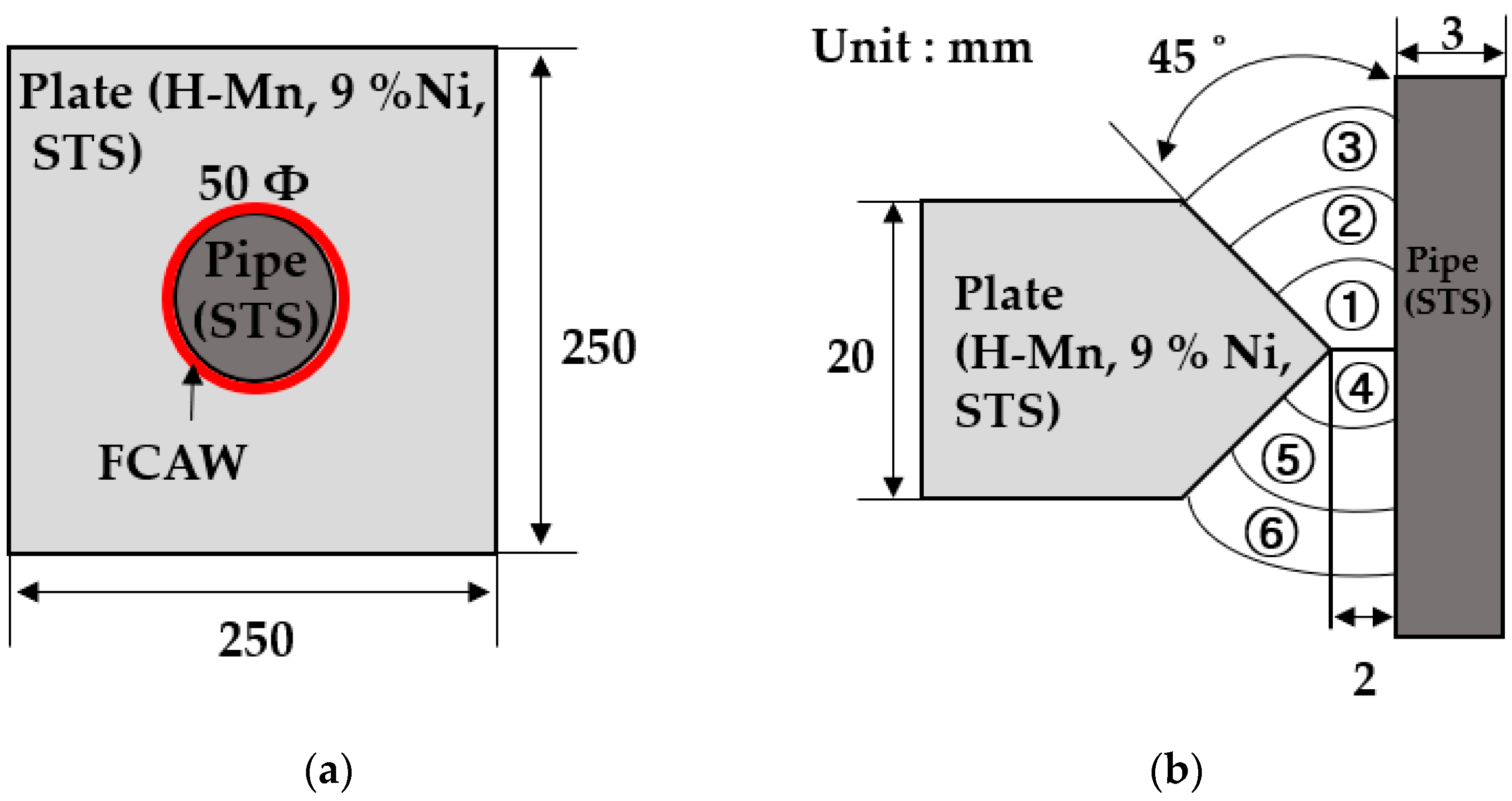
2.1. Specimen Preparation

The materials used in the experimental examination were conventional cryogenic steels, i.e., 9% Ni steel, STS, and high-manganese austenitic steel, and they were welded with an STS pipe. Table 1 and Table 2 present the chemical compositions and mechanical properties of each type of steel. Figure 1 shows the shape of the specimen and the groove shape. The dimensions of the plate used were 250 mm × 250 mm × 20 mm (length × width × thickness). The groove was K-shaped with an angle of 45° on both sides. Moreover, the pipe thickness was 3 mm, and the diameter was 50 mm. The welded joints were subjected to multi-layer flux-cored arc welding (FCAW) with a K-groove (Figure 1b), which is a welding process widely used in LNG storage tank construction. The top of the plate was welded, and the bottom was welded with the same procedure. The inter-pass temperature was 110 °C.
Table 3 presents the welding conditions used in this study. Table 4 and Table 5 present the chemical composition and mechanical properties of the welding consumables. For each specimen, different welding consumables were matched, and suitable commercial welding consumables were selected. The STS specimens show the over-matching joint, and the high-manganese austenitic steels and 9% Ni steel show the undermatching joint. The high-manganese austenitic steels and 9% Ni steel had similar yield strengths and tensile strengths (nearly 1 GPa); however, there was no suitable welding consumable. Therefore, undermatching joints were manufactured using both materials.

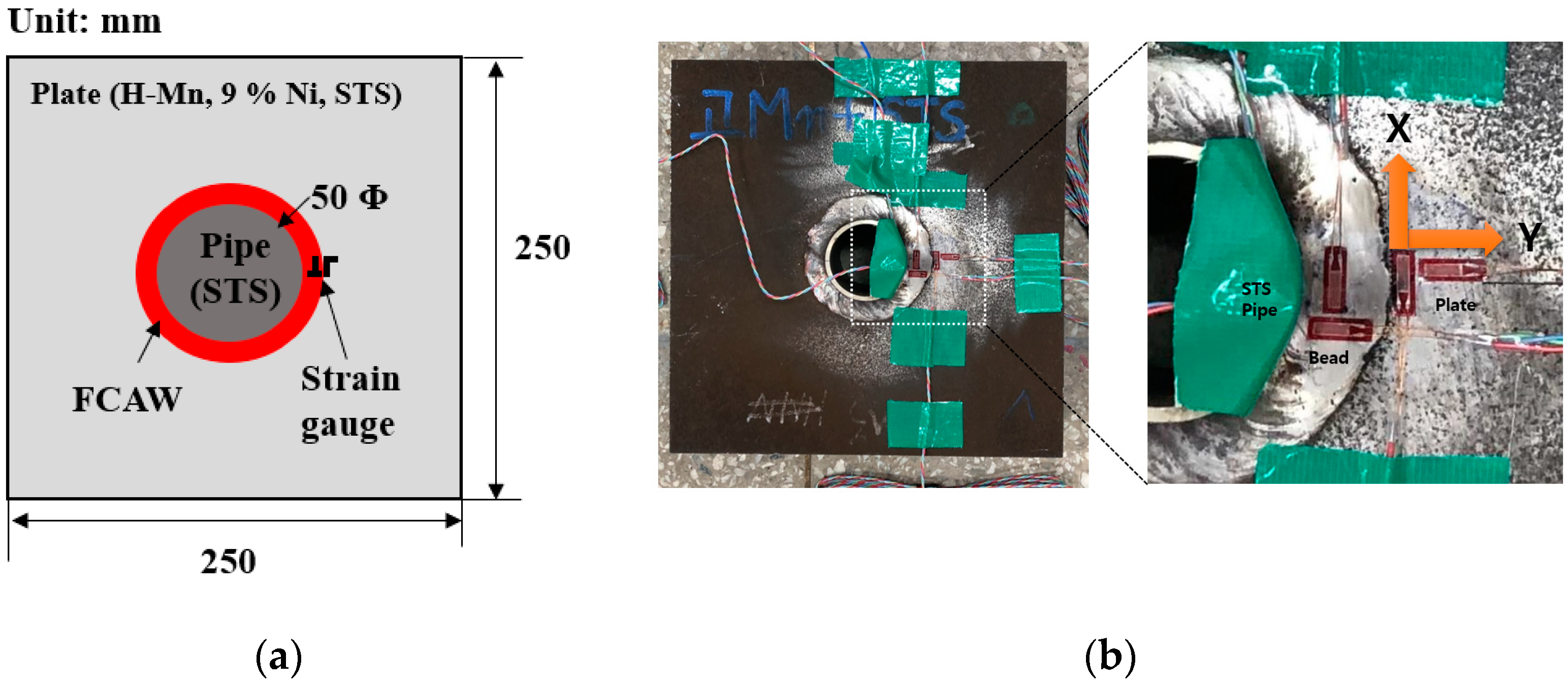
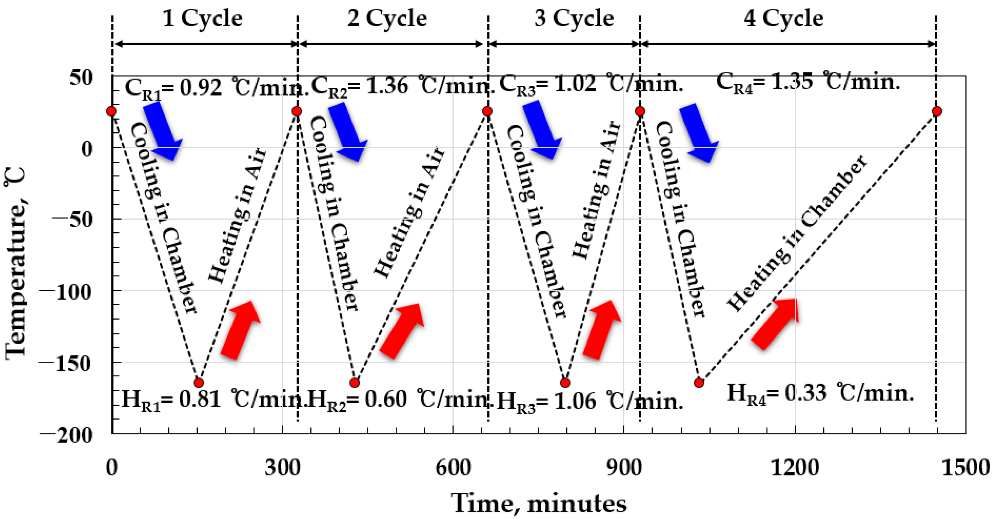
2.2. Measurement of Stress Change via Thermal Cycles

Because all the cryogenic steels used in this study had different thermal expansion coefficients, the shrinkage and expansion according to the temperature change were different. The thermal expansion coefficients of the high-manganese austenitic steels, 9% Ni steel, and STS were 5, 8, and 12.5 μm/(m·°C), respectively. In the case of dissimilar bonding, stress was generated according to the amount of thermal expansion. To evaluate the effect of the temperature on the stress, a test specimen was prepared, as shown in Figure 2. STS304 pipes were joined to three types of cryogenic plates to simulate the unloading process of LNG gas and repeated loading–unloading while examining the stress change at the dissimilar material joint. The thermal stress was measured using a strain gauge in the plate, weld bead, and pipe during the loading–unloading process. A dynamic datalogger was used to record the temperature changes during the experiment to observe the strain change according to the change in temperature. In the experiment, the thermal stress of the cryogenic steel plate was analyzed to examine the thermal stress caused by the influence of the difference in the thermal expansion coefficients of the dissimilar weld joints. Figure 3 shows the process of simulating the loading–unloading process of LNG, indicating the cooling and heating conditions. Liquid nitrogen was used to cool the specimen in a cooling chamber. The test temperature in the cooling chamber was controlled automatically. The cooling temperature was set to −165 °C with consideration of the temperature when the LNG was in storage. After the cooling, the door of the chamber was opened to simulate the unloaded state of LNG, and the temperature was increased to room temperature. To observe the change when the temperature increased to room temperature inside the chamber, the temperature in the cooling chamber was increased in the last (fourth) cycle. After cooling, a separate heating system was not used to increase the temperature in all the cycles.
A total of four cycles were performed, and the heat and cooling rates in each process are indicated in Figure 3. The cooling and heating rates were not specified before the experiment, and the experiments were conducted under similar environmental conditions. The cooling and heating rates were similar, as shown in Figure 3. The cooling rate (CR) was 0.92–1.35 °C/min, and the heating rate (HR) was 0.33–1.06 °C/min. The experiment was started at room temperature; the temperature was subsequently reduced to −165 °C and then increased to room temperature in air. This process was repeated four times.

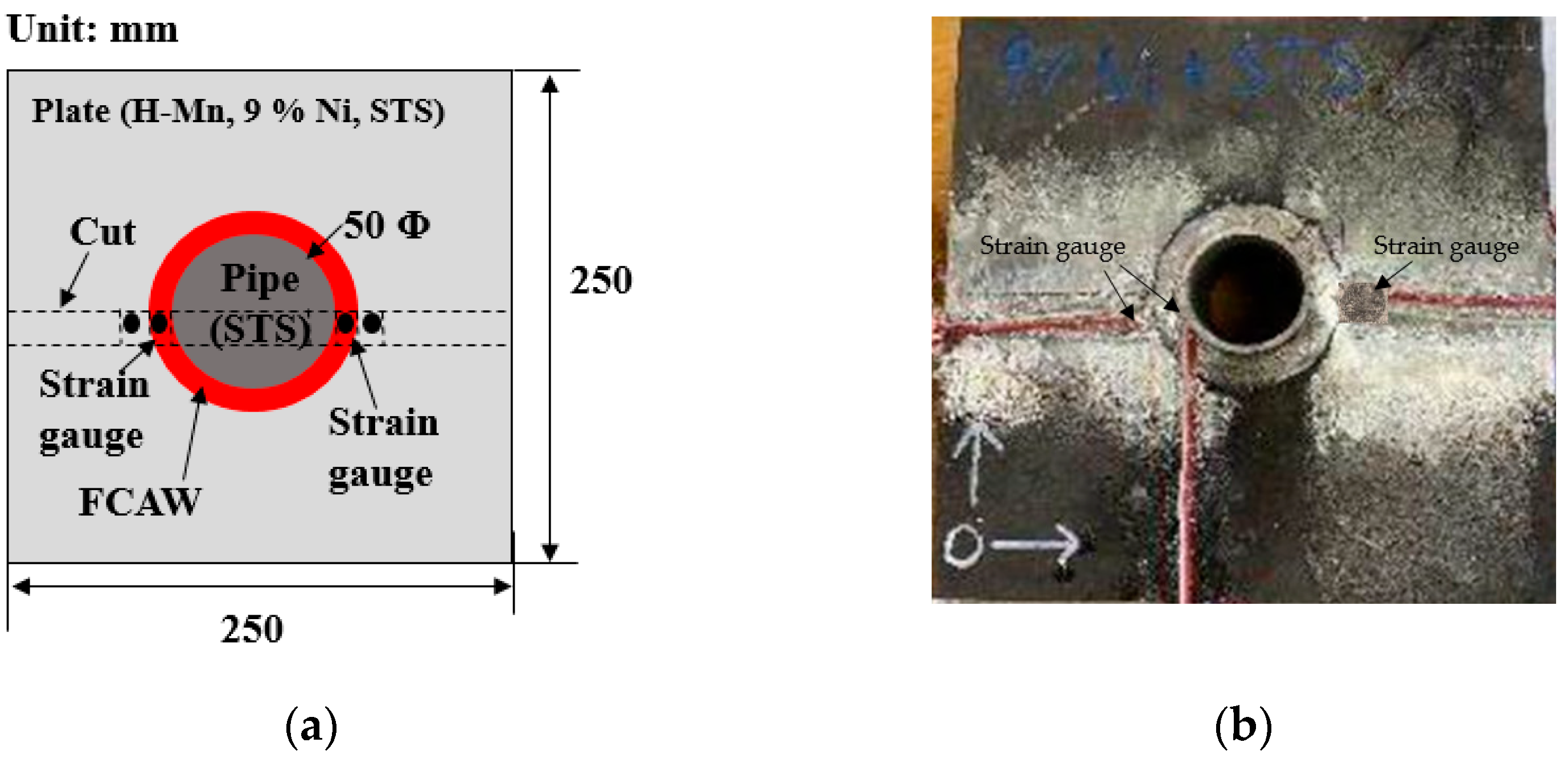
2.3. Welding Residual Stress Measurements

There are several methods for measuring the welding residual stresses in weld joints. The experimental methods include destructive and nondestructive methods. A destructive method was used in this study to measure the welding residual stress because destructive methods are the most widely used and accurate methods. Destructive methods include the hole-drilling method, cutting method, and X-ray method, and the cutting method was used in this experiment because it is the most reliable destructive method. Figure 4 shows the position of welding residual stress measurement using a two-axis strain gauge. The welding residual stress was measured in the fusion line of the pipe and plate because the strength mismatch area was the worst position in the bond line. In addition, the strain gauge was attached to a symmetric position to ensure the reliability of the measured residual stress value. The specifications of the strain gauges are presented in Table 6. FCA-1 is a two-axis strain gauge for cryogenic temperature conditions. The gauge length, width, face dimension, and resistance were 1 mm, 0.7 mm, 4.5 Φ, and 120 Ω, respectively. The welding residual stress was measured using the cutting method with the plate and pipe of the weld joints. When measuring the welding residual stress via the cutting method, it was necessary to control the heat generated by setting the cutting speed. Therefore, the cutting speed was maintained at 2 mm/min, and the heat generated during cutting was controlled using oil and water. To completely remove the welding residual stress distributed in the weld zone, cutting was performed along the longitudinal, width, and thickness directions. Finally, after cutting in all the directions, the strain was measured, and the initial welding residual stress was calculated using Hooke’s law.

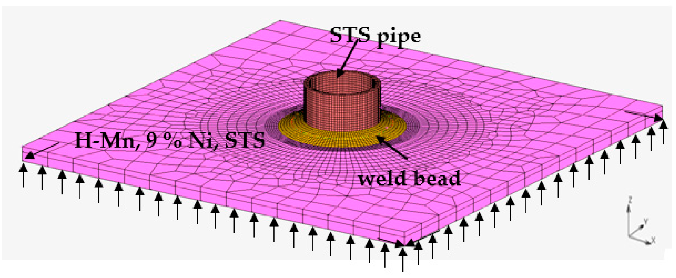
2.4. Finite-Element Analysis of Welding Residual Stress

A three-dimensional thermoelastic analysis was performed using the commercial software MSC Marc 2018 to determine the residual stress distribution characteristics of the dissimilar material welds. The model used for the finite-element (FE) analysis is shown in Figure 5. It had the same shape and dimensions as the test specimens. The Goldak model was used as the heat source model to perform a thermal–elastic–plastic FE analysis. A symmetric condition was applied in the FE analysis, and the symmetric path was fixed in all directions. The mechanical properties, including the yield stresses, tensile strengths, elastic moduli, and thermal expansion coefficients, of the base metals and welding consumables are presented in Table 2 and Table 5, respectively. The material properties of the base metals and welding consumables were experimentally derived; however, the thermal expansion coefficients of the welding consumables were applied of same value of base metals, because the materials of the welding consumables were similar to those of the base metals. The effects of the temperature change on the tensile strength and yield stress were significant; therefore, the strength due to temperature change was used in the FE analysis.

3. Test Results and Discussion

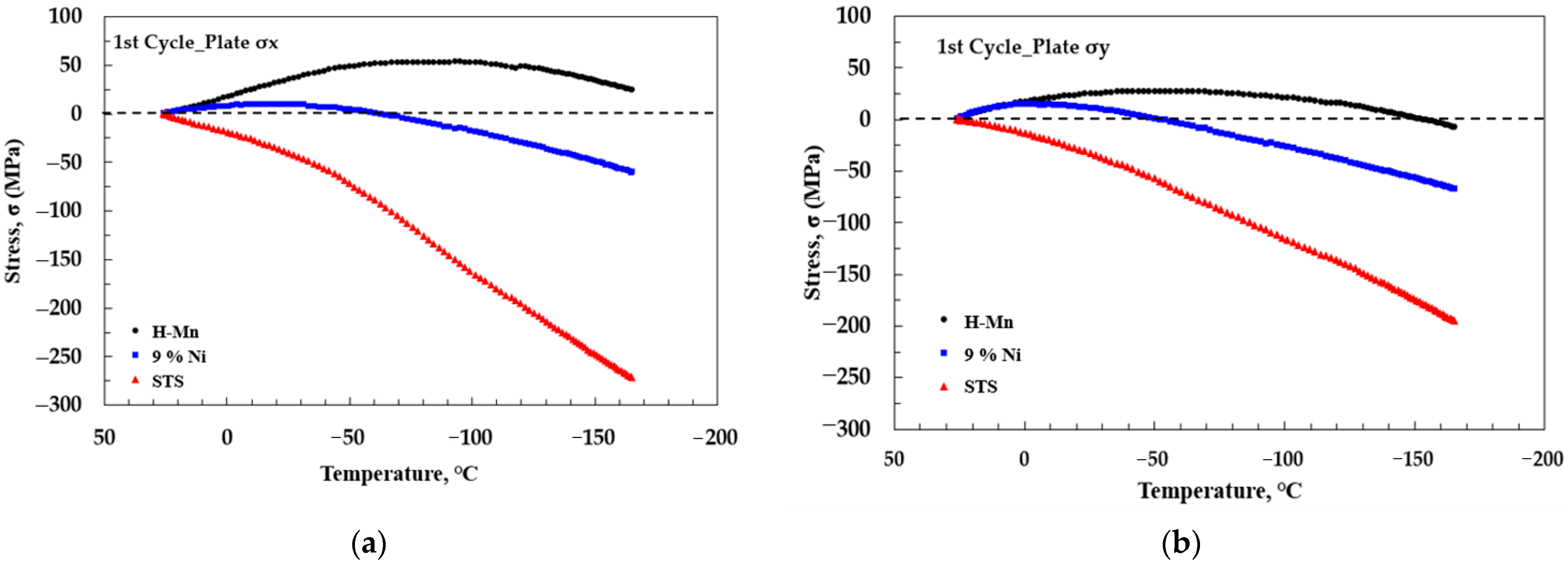
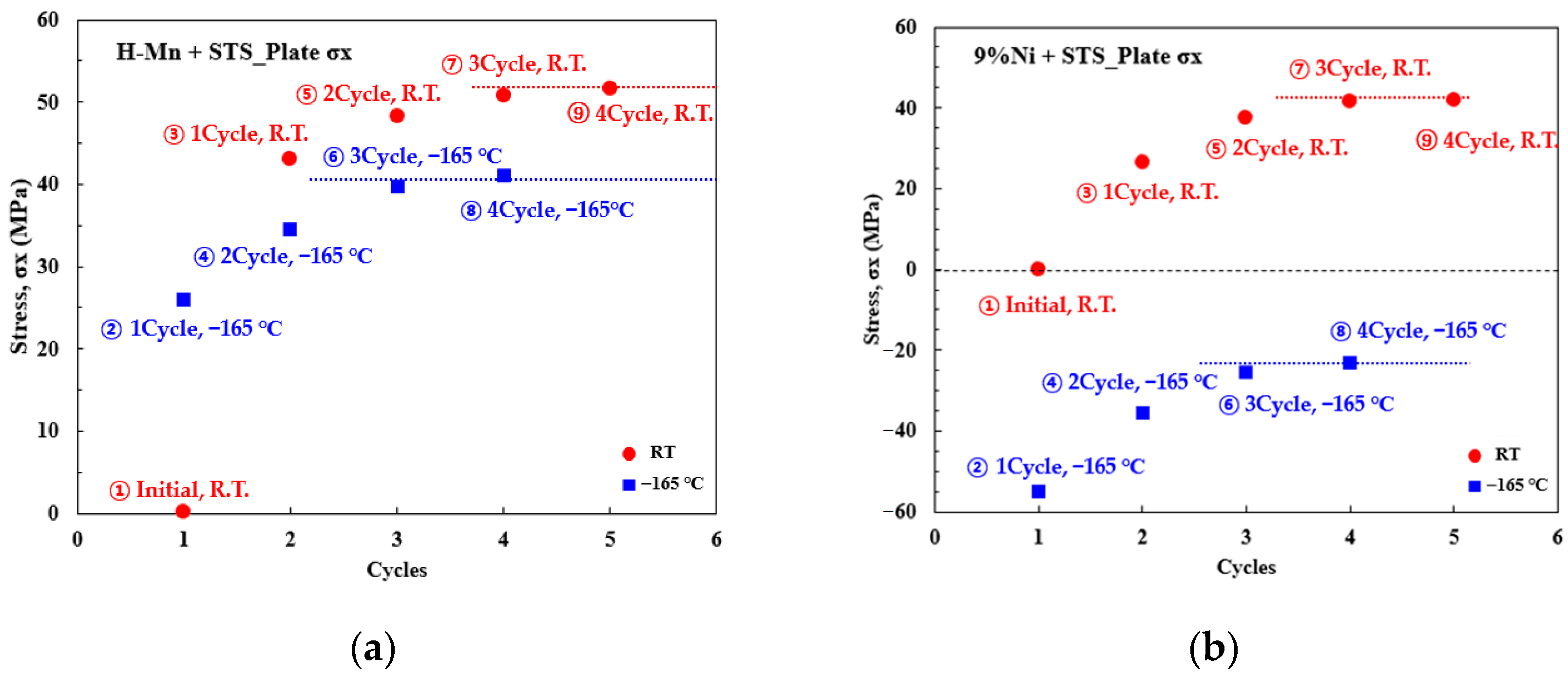
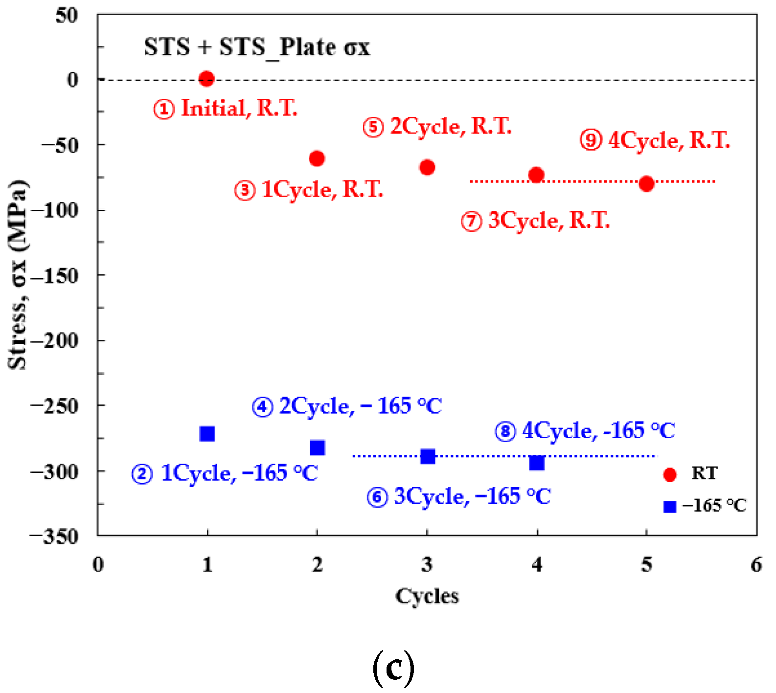
3.1. Stress Distribution according to LNG Loading–Unloading Simulation

The stress changes occurring at dissimilar weld joints during the loading–unloading process of the LNG storage tank were evaluated. Because dissimilar weld joints have different thermal expansion coefficients, stress is generated according to the temperature change.
Figure 6 shows the stress behaviors of σx and σy for the three types of cryogenic steels. The loading–unloading test was performed four times at room temperature and –165 °C, and the results of one test cycle are presented in Figure 7. The graph shows the process of stress generation with respect to the temperature.
The high-manganese austenitic steels (with the smallest thermal expansion coefficient) exhibited mostly tensile stress with the temperature change. In the case of STS (with the largest thermal expansion coefficient), compressive stress was generated as the temperature decreased, and the compressive stress was maximized at −165 °C. Because it was the same type of welding as that of the STS pipe, it had the same thermal expansion coefficient; therefore, expansion at cryogenic temperatures was freely generated, and a high compressive stress was generated. In contrast, because the thermal expansion coefficient of the 9% Ni steel was between those of the high-manganese austenitic steels and STS, the stress behavior was distributed between the two steel types. The tensile stress was distributed up to approximately −55 °C, and the compressive stress was distributed at temperatures below −55 °C. Because the value of the thermal expansion coefficient was smaller than that of the STS pipe, the degree of shrinkage depended on the temperature change. Therefore, the compressive stress was more widely distributed than that of the high-manganese austenitic steels, and the compressive stress was lower than that of the STS. The transverse stress component (σy) exhibited behavior similar to σx.
The heat-cycle experiment was performed four times, and Figure 7 shows the final stress values at each cycle for the three cryogenic steels. At room temperature, the initial stress was set to zero by ignoring the residual stress caused by welding. For the high-manganese austenitic steels, a tensile stress of approximately 26 MPa was distributed at an LNG storage temperature of −165 °C. In general, compressive stress is generated by shrinkage in a low-temperature environment. However, in the case of dissimilar welding, a significant amount of shrinkage occurred in the STS pipe owing to the difference in the thermal expansion coefficient. Therefore, it is believed that the tensile stress was dis-tributed in the high-manganese austenitic steels. When all the LNG was unloaded from the LNG storage tank and the temperature increased from −165 °C to room temperature, a higher tensile stress of approximately 43 MPa was distributed owing to the expansion caused by the temperature rise. This phenomenon occurred during the fourth cycle, and from the third cycle, the stress in the cooling and heating processes converged to a constant value. However, for the 9% Ni steel, compressive stress was generated during the cooling process, and tensile stress was generated during the heating process. The thermal expansion coefficient of the 9% Ni steel was smaller than that of the high-manganese austenitic steels and larger than that of the STS; therefore, tension and compression were observed in the loading–unloading process. In contrast, for the STS, because it has the same thermal expansion coefficient as the STS pipe, the shrinkage and expansion were not affected by the temperature change. In the cooling process, a compressive stress of approximately −270 MPa was generated owing to contraction, and even when the temperature was increased to room temperature again, the compressive stress generated during the cooling process was not recovered and approximately −60 MPa of compressive stress remained. After three cycles, the compressive stress converged to a constant value, as for other cryogenic steels. For the STS, which had homogeneous welding, −60 MPa of compressive stress remained at room temperature, despite the initial stress being zero at room temperature, owing to the influence of the welding consumable. Because it is difficult to use the same material as the welding consumable, it is considered that the compressive stress remains. In general, assuming that the minimum life of an LNG storage tank is 20 years, approximately 1000 operations are repeated. As a result of simulating the loading–unloading process four times in this experiment, it converged to a certain value from three or more times; therefore, it is believed that it will converge to the same value in further repeated experiments. In the case of high-manganese austenitic steels, the stress of 40 to 50 MPa is distributed during the loading–unloading process of LNG; in the case of 9% Ni steel, the stress of −23 to 42 MPa is believed to be distributed; and in the case of STS, the stress of –290 to −80 MPa is believed to be distributed. The stresses caused by the temperature change distributed in the cryogenic steels were all below the yield stress, and the stress generated during the loading–unloading process at the dissimilar weld was not considered a major safety problem.

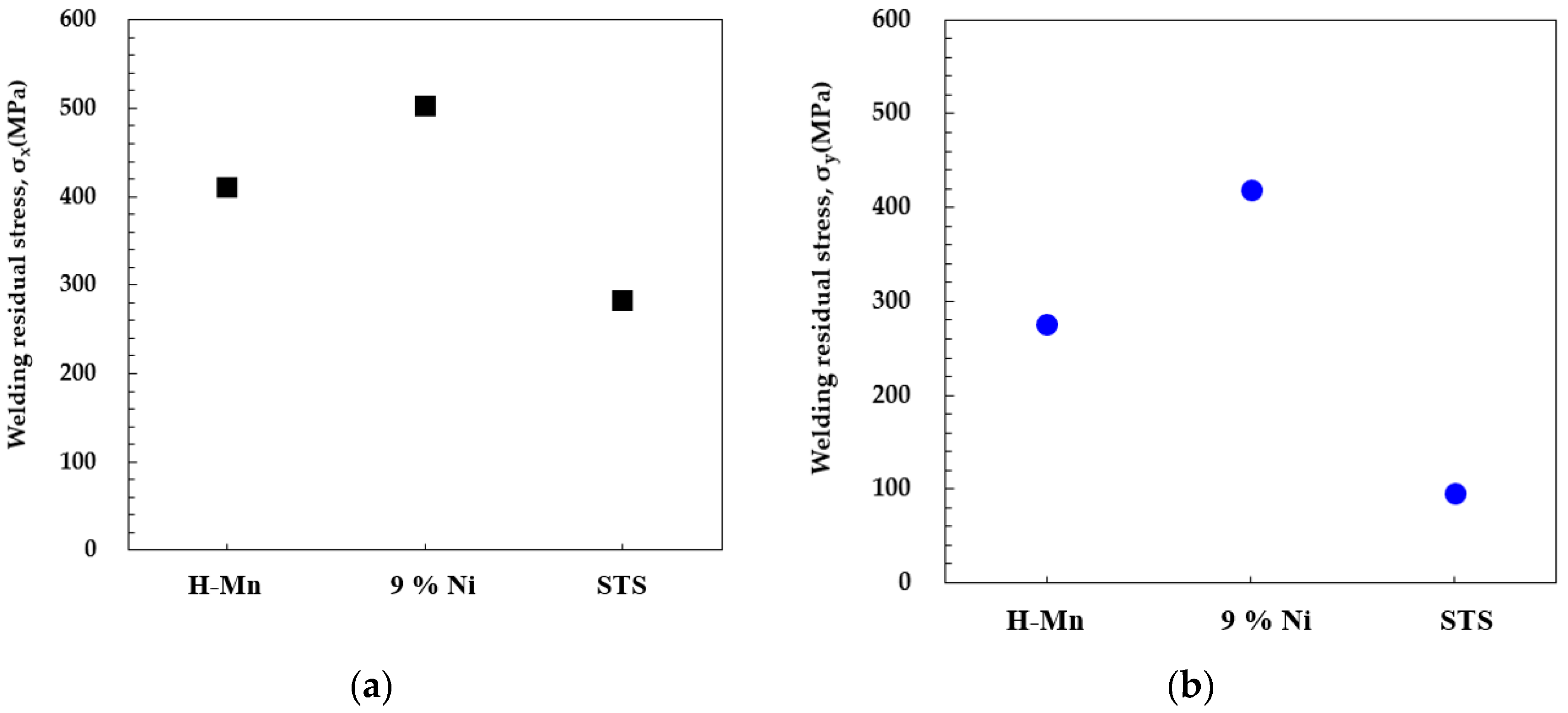
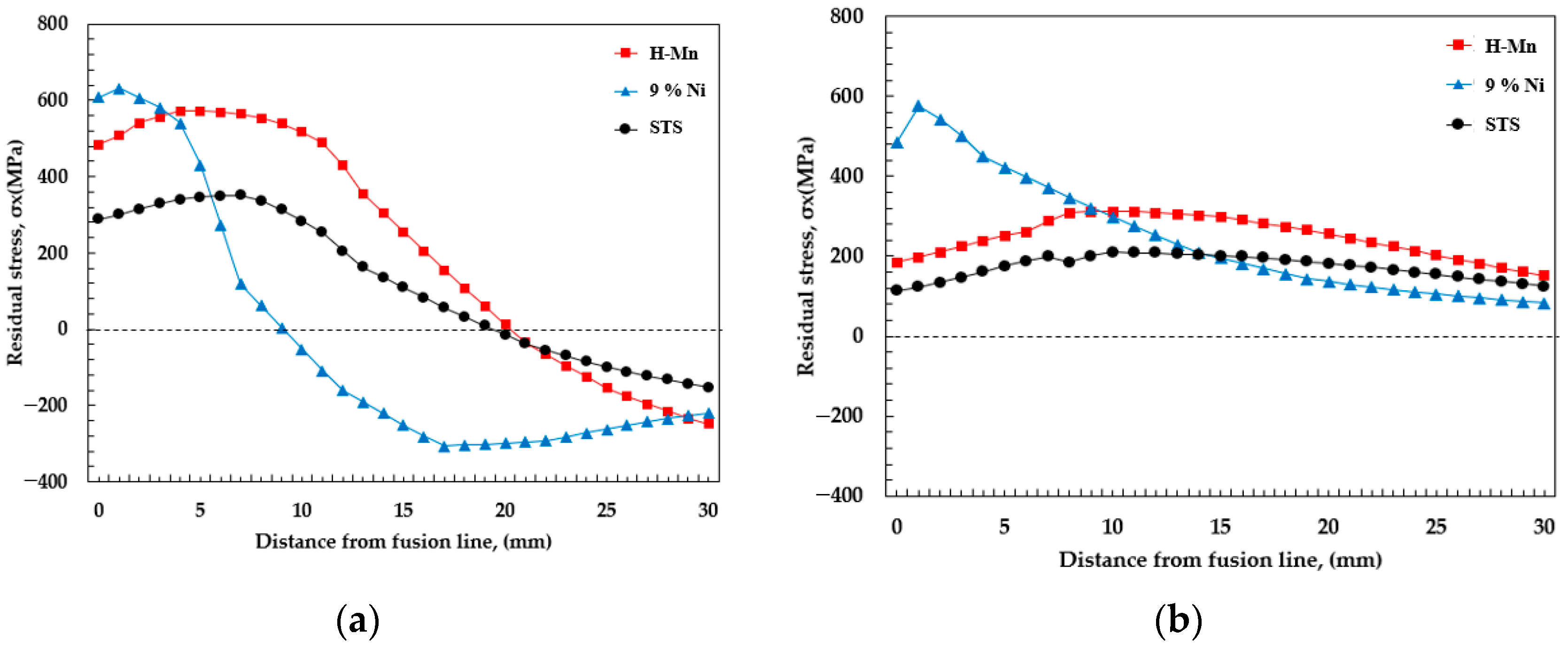
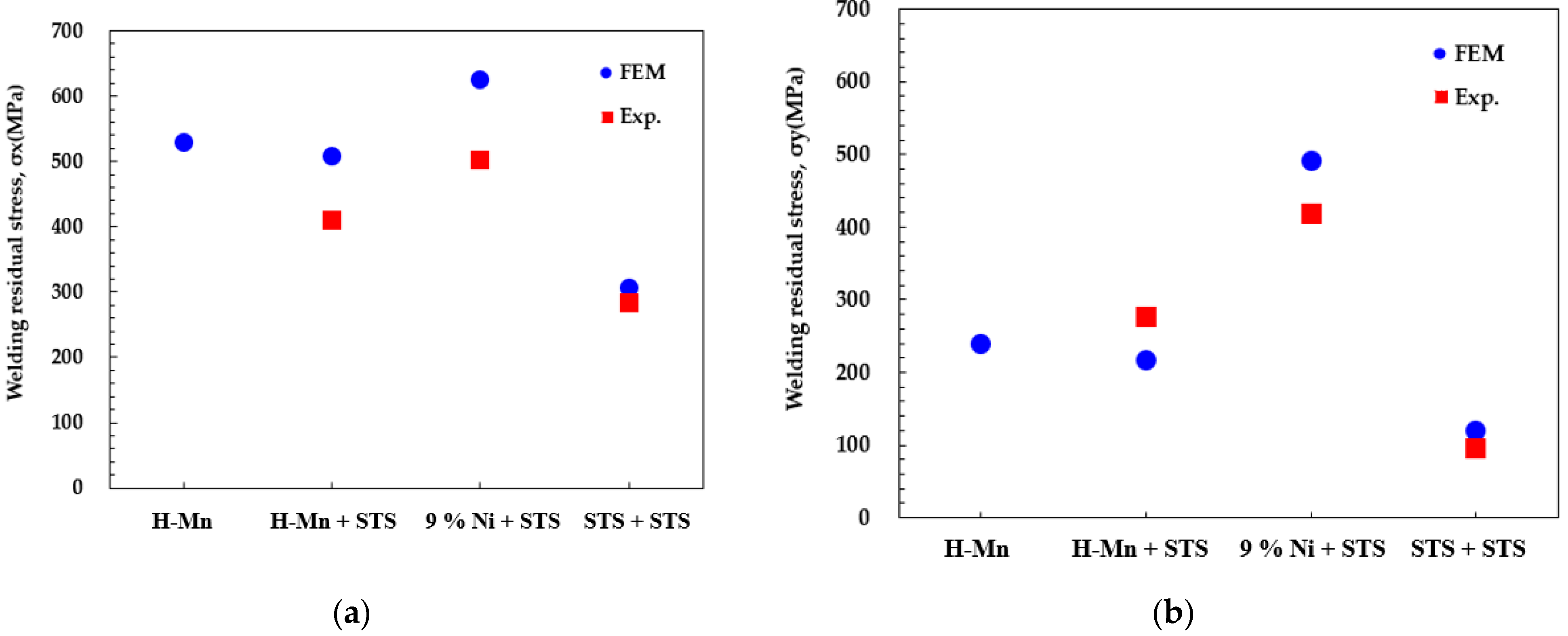
3.2. Welding Residual Stress Distribution in Dissimilar Weld Joints

In the case of homogenous welding, the thermal expansion coefficients of the materials are identical, and because the materials contract and expand to the same degrees, the residual stress in the weld was believed to be the same as that in the previous research. Because the amounts of shrinkage and expansion are also different, the distribution of residual stress is different from that of the homogenous weld. For example, in the case of high-manganese austenitic steels and STS304 dissimilar material welding, the thermal expansion coefficient of high-manganese austenitic steels is smaller than that of STS304 at the same temperature; therefore, the amount of expansion due to the temperature change was smaller in the high-manganese austenitic steels than in the STS304. Figure 8a shows the welding residual stress in the weld line direction, i.e., σx, for high-manganese austenitic steels, 9% Ni steel, and STS. The three materials exhibited the maximum tensile stress on the fusion line, which was almost equivalent to the yield stress. The residual stress value, i.e., σx, was 410 MPa for the high-manganese austenitic steels, 502 MPa for the 9% Ni steel, and 282 MPa for the STS. Figure 8b shows the welding residual stress in the transverse direction, i.e., σy, for high-manganese austenitic steels, 9% Ni steel, and STS. The welding residual stress exhibited almost the same behavior as σx. The residual stress, i.e., σy, was 276 MPa for the high-manganese austenitic steels, 491 MPa for the 9% Ni steel, and 120 MPa for the STS. The maximum welding residual stresses were identical among the different material yield stresses.
In the loading–unloading process, the stresses caused by the temperature difference and welding residual stress are considered to overlap. An FE analysis was performed to evaluate the welding residual stress distribution for dissimilar weld joints. The residual stress measurement point was identical to the measurement point in the cutting method. The residual stress distributions for the three types of materials are shown in Figure 9. The residual stress distribution in the welding line direction (σx) is shown in Figure 9a, and the high tensile residual stress exceeding the yield stress was distributed in the HAZ, including F/L, for all three types of steels. The maximum tensile residual stress was distributed on the fusion line, and the tensile stress decreased from the weld line to the base metal, exhibiting a typical welding residual stress distribution. The residual stress was 484 MPa for high-manganese austenitic steels, 603 MPa for 9% Ni steel, and 288 MPa for STS. For the high-manganese austenitic steels and STS, the area where the tensile residual stress was distributed was wide. For the 9% Ni steel, the highest tensile residual stress was observed; however, the area where the tensile residual stress was distributed was narrower than those for the two other steels. Figure 9b shows the transverse-direction stress, i.e., σy, which represented the tensile stress in all the materials. Figure 10 shows a comparison of the residual stresses obtained from the experiment and FE analysis. The FE-analysis stress value was high; however, the difference from the experimental value was insignificant. Additionally, in the FE analysis, the welding residual stresses of the homogenous high-manganese austenitic steels were slightly higher than those for dissimilar welding; however, the difference was insignificant. It is believed that there is no significant difference in the welding residual stress distribution between homogeneous and dissimilar weld joints. From this result, it was determined that in the case of dissimilar welding, the stress caused by the residual stress is higher than the temperature difference.

4. Conclusions

In this study, experimental and analytical research was performed to evaluate the stress distribution in an LNG storage tank under loading–unloading conditions with high-manganese austenitic steels, 9% Ni steel, and STS, having dissimilar STS pipe weld joints. The stress was generated at the dissimilar joint during the loading–unloading process owing to the different thermal expansion coefficients. The following results were obtained by examining the characteristics of the stress occurring at the joint during the LNG loading–unloading process and the characteristics of the welding residual stress occurring at the dissimilar material weld.
(1)
When high-manganese austenitic steels and the STS pipe were joined, a tensile stress was generated at the dissimilar weld joint owing to the temperature difference generated during the LNG loading–unloading process. For the high-manganese austenitic steels, little shrinkage occurred; therefore, tensile stress was generated even at cryogenic temperatures. STS has a homogenous weld joint and identical thermal expansion coefficients; therefore, the shrinkage and expansion were not affected by the temperature change. High compressive stress was generated at cryogenic temperatures.
(2)
The measurement of the welding residual stress of the dissimilar weld joint indicated that the stress value was close to the yield stress of each material. A numerical analysis confirmed that there was no significant difference between the maximum residual stresses of the homogeneous and dissimilar welds.
(3)
It is believed that the stress generated by the temperature change and the welding residual stress overlapped and occurred during the loading–unloading process of the LNG tank; however, the final tensile stress was about 430 MPa, which below the yield stress was distributed in the storage tank, and it did not affect the safety of the structure.

Author Contributions

G.A. and J.P. jointly conceived and designed the experiment, performed the experiment, and conducted the data analysis. G.A., H.P. and W.L. analyzed the data, plotted the figures, and wrote this paper. J.P. and I.H. provided scientific guidance. All authors have read and agreed to the published version of the manuscript.

Funding

This study was funded by Chosun University (grant number 2021). This research was supported by the Basic Science Research Program through the National Research Foundation of Korea (NRF) funded by the Ministry of Education (NRF-2017R1D1A1B04029150).

Institutional Review Board Statement

Not applicable.

Informed Consent Statement

Not applicable.

Data Availability Statement

Data sharing is not applicable.

Acknowledgments

This study was supported by a research grant awarded by Chosun University in 2021. This research was supported by the Basic Science Research Program through the National Research Foundation of Korea (NRF), funded by the Ministry of Education (NRF-2017R1D1A1B04029150).

Conflicts of Interest

The authors declare no conflict of interest.

References

  1. Zhao, T.; Yun, K.; Lee, H. A Study on Estimating Ship Emission-Focusing on Gwangyang Port and Ulsan Port. J. Korea Port. Econ. Assoc. 2019, 35, 93–108. [Google Scholar] [CrossRef]
  2. Paula, S. From maritime salvage to IMO 2020 strategy: Two actions to protect the environment. Mar. Pollut. Bull. 2021, 170, 112590. [Google Scholar]
  3. Park, H.; Park, H.; Ha, S.; Park, S.; Lee, K. A Study on the Industrial Competitiveness of Ballast Water Management System in Compliance with the International Maritime Organization Ballast Water Management Convention in Korea. J. Korean Soc. Mar. Environ. Saf. 2020, 26, 483–492. [Google Scholar] [CrossRef]
  4. Seddiek, I.S.; Elgohary, M.M. Eco-friendly selection of ship emissions reduction strategies with emphasis on SOx and NOx emissions. Int. J. Nav. Archit. Ocean. 2014, 6, 737–748. [Google Scholar]
  5. Awad, O.I.; Ma, X.; Kamil, M.; Ali, O.M.; Ma, Y.; Shuai, S. Overview of polyoxymethylene dimethyl ether additive as an eco-friendly fuel for an internal combustion engine: Current application and environmental impacts. Sci. Total Environ. 2020, 715, 1–16. [Google Scholar] [CrossRef] [PubMed]
  6. Jiubing, S.; Siyuan, Y.; Zhichao, L.; Yanping, X.; Tan, N. Design and analysis of boil-off gas reliquefaction processes for the LNG-fueled ships. Appl. Therm. Eng. 2021, 199, 1–10. [Google Scholar]
  7. Park, S.; Paik, J. A hybrid method for the safety zone design in truck-to-ship LNG bunkering. Ocean. Eng. 2022, 243, 1–10. [Google Scholar] [CrossRef]
  8. Machida, S.; Deguchi, A.; Kagawa, H. Brittle fracture characteristics of heavy gauge 9% Ni steel plate for large scale LNG strage tank. J. High. Press. Inst. Jpn. 1993, 31, 31–38. [Google Scholar]
  9. Niu, W.; Lina, J.; Ju, Y.; Fu, Y. The daily evaporation rate test and conversion method for a new independent type B LNG mock-up tank. Cryogenics 2020, 111, 1–11. [Google Scholar] [CrossRef]
  10. Kang, S.; Kim, M.; Kim, Y.; Shin, Y.; Lee, H. A Study on the Fracture Toughness Characteristics of FCAW Weldment of Steel for Offshore Structures. J. Korea Weld. Join. Soc. 2004, 22, 57–63. [Google Scholar]
  11. IGC Code. Code for the Construction and Equipment of Ships Carrying Liquefied Gases in Bulk; International Maritime Organization: London, UK, 2020.
  12. IGF Code. International Code of Safety for Ships Using Gases or Other Low-Flashpoint Fuels; International Maritime Organization: London, UK, 2020.
  13. Interim Guidelines on the Application of High Manganese Austenitic Steel for Cryogenic Service; International Maritime Organization: London, UK, 2018.
  14. An, G.; Hong, S.; Park, J.; Ro, C.; Han, I. Identification of Correlation Between Fracture Toughness Parameters of Cryogenic Steel Weld Joints. J. Weld. Join. 2017, 35, 82–87. [Google Scholar] [CrossRef] [Green Version]
  15. Han, I.; Lee, B. Microstructure and Mechanical Properties of Cryogenic High-Manganese Steel Weld Metal. Int. J. Offshore Polar Eng. 2017, 27, 260–265. [Google Scholar] [CrossRef]
  16. Lee, J.; Kim, K.; Kim, Y.; Yu, C. Fatigue Strength Assessment of High Manganese Steel for LNG CCS. J. Soc. Nav. Archit. Korea 2014, 51, 246–253. [Google Scholar] [CrossRef] [Green Version]
  17. Lee, Y.; Lho, B. Improvement of Insulation System for LNG Storage Tank Base Slab. J. Korea Inst. Struct. Maint. Insp. 2010, 14, 141–147. [Google Scholar]
  18. RESOLUTION MSC.370(93). Amendments to The International Code for The Construction and Equipment of Ships Carrying Liquefied Gases in Bulk. 2014. Available online: https://www.palaureg.com/product/resolution-msc-37093-amendments-to-the-international-code-for-the-construction-and-equipment-of-ships-carrying-liquefied-gases-in-bulk-igc-code/ (accessed on 8 February 2022).
  19. RESOLUTION MSC.391(95). Adoption of The International Code of Safety for Ships using Gases or Other Low-Flashpoint Fuels. 2015. Available online: https://www.imo.org/en/KnowledgeCentre/IndexofIMOResolutions/Pages/MSC-2014-15.aspx (accessed on 8 February 2022).
  20. Han, X.; Tan, J.; Wang, R.; Yin, W. A study on welding residual stress in elliptical tube to tube sheet joint of a phthalic anhydride switch condenser. Procedia Eng. 2015, 130, 544–551. [Google Scholar] [CrossRef] [Green Version]
  21. Machida, S.; Ishikura, N.; Kubo, N.; Katayama, N.; Muramoto, S.; Hagiwara, Y.; Arimochi, A. Brittle fracture characteristics of heavy thickness 9% Ni steel plate and its applicability to large scale LNG storage tanks. J. High. Press. Inst. Jpn. 1991, 29, 25–39. [Google Scholar]
  22. Jin, D.; Hou, C.; Shen, L. Effect of welding residual stress on the performance of CFST tubular joints. J. Constr. Steel Res. 2021, 184, 1–15. [Google Scholar] [CrossRef]
  23. Chiocca, A.; Frendo, F.; Bertini, L. Evaluation of residual stresses in a pipe-to-plate welded joint by means of uncoupled thermal-structural simulation and experimental tests. Int. J. Mech. Sci. 2021, 199, 1–15. [Google Scholar] [CrossRef]
  24. Huang, B.; Lu, M.; Cao, Y.; Yang, F. Experimental study on residual performance of welded hollow spherical joints subjected to axial compression after a fire. Structures 2021, 30, 996–1005. [Google Scholar] [CrossRef]
  25. Lim, Y.; Morisada, Y.; Liu, H.; Fujii, H. Ti-6Al-4V/SUS316L dissimilar joints with ultrahigh joint efficiency fabricated by a novel pressure-controlled joule heat forge welding method. J. Mater. Process. Technol. 2021, 298, 1–11. [Google Scholar] [CrossRef]
Figure 1. Test specimen dimensions and groove shape: (a) configuration of the test specimen; (b) groove shape.
Metals 12 00405 g001
Figure 2. Location of strain-gauge attachment: (a) schematic and (b) specimen photograph used to measure the stress history in the loading and unloading conditions.
Metals 12 00405 g002
Figure 3. Heating and cooling rates in the loading and unloading conditions.
Metals 12 00405 g003
Figure 4. Location of strain-gauge attachment: (a) schematic and (b) specimen photograph.
Metals 12 00405 g004
Figure 5. FE-analysis model and boundary conditions.
Metals 12 00405 g005
Figure 6. Stress behaviors of (a) σx and (b) σy with the three types of cryogenic steels in the 1st thermal cycle of the experiment.
Metals 12 00405 g006
Figure 7. Stress values at each cycle for (a) high-manganese austenitic steel, (b) 9% Ni steel, and (c) STS at room temperature and −165 °C in the experiment.
Metals 12 00405 g007aMetals 12 00405 g007b
Figure 8. Welding residual stresses in the (a) weld line direction, i.e., σx, and (b) transverse direction, i.e., σy, for high-manganese austenitic steels, 9% Ni steel, and STS specimens prepared via the cutting method.
Metals 12 00405 g008
Figure 9. Welding residual stress distributions for the three types of materials: (a) weld line-direction stress, i.e., σx, and (b) transverse-direction stress, i.e., σy, obtained from the FE analysis.
Metals 12 00405 g009
Figure 10. Comparison of the residual stresses obtained from the experiment and the FE analysis: (a) weld line-direction stress, i.e., σx, and (b) transverse-direction stress, i.e., σy.
Metals 12 00405 g010
Table 1. Chemical compositions of the cryogenic steels.
MaterialsChemical Composition (Mass, %)
CSiMnNiPSCr
H-Mn0.35–0.550.10–0.5022.5–25.50-Max. 0.03Max. 0.01-
9% Ni0.0510.2520.6609.4480.0100.001-
STS3040.0160.211.728.260.0290.02019.25
Table 2. Mechanical properties of the cryogenic steels.
MaterialsYield Strength (MPa)Tensile Strength (MPa)Elastic Modulus (GPa)Thermal Expansion Coefficient (μm/(m·°C))
25 °C−165 °C25 °C−165 °C25 °C−165 °C25 °C−165 °C
H-Mn432773879131217518695
9% Ni6689257071046195205128
STS30427543266815272012141612.5
Table 3. Welding conditions.
Welding ConditionsFCAW
Heat input8–10 KJ/cm
Groove shapeK-groove
Welding consumableSize Φ (mm)1.2
Welding parametersCurrent (A)180
Voltage (V)28–29
Speed (cm/min)30–35
Position1G
Shielding gasGas type80 % Ar/20 % CO2
Table 4. Chemical compositions of the welding consumables.
MaterialsChemical Composition (wt.%)
CSiMnNiPS
PT-400HM0.25-18–244.0–8.0--
DW-N709SP0.010.122.463.40.0120.003
K-316LT0.030.651.2012.7--
Table 5. Mechanical properties of the welding consumables.
MaterialsYield Strength
(MPa)
Tensile Strength
(MPa)
Elastic Modulus
(%)
Thermal Expansion Coefficient (μm/(m·°C))
PT-400HM≥400≥660≥229
DW-N709SP4407124312
K-316LT4205603816
Table 6. Specifications of the strain gauges.
Gauge
Pattern
Basic TypeGauge LGauge WBacking LBacking WResistance
Metals 12 00405 i001FCA-11 mm0.7 mm4.5 Φ4.5 Φ120 Ω
Publisher’s Note: MDPI stays neutral with regard to jurisdictional claims in published maps and institutional affiliations.

