Review

Recent Advances in Magnetostrictive Tb-Dy-Fe Alloys

State Key Laboratory for Advanced Metals and Materials, University of Science and Technology Beijing, Beijing 100083, China
*
Author to whom correspondence should be addressed.
Metals 2022, 12(2), 341; https://doi.org/10.3390/met12020341
Submission received: 31 December 2021 / Revised: 8 February 2022 / Accepted: 10 February 2022 / Published: 15 February 2022
(This article belongs to the Special Issue Advances in Metal-Containing Magnetic Materials)

Abstract

:
As giant magnetostrictive materials with low magnetocrystalline anisotropy, Tb-Dy-Fe alloys are widely used in transducers, actuators and sensors due to the effective conversion between magnetic energy and mechanical energy (or acoustic energy). However, the intrinsic brittleness of intermetallic compounds leads to their poor machinability and makes them prone to fracture, which limits their practical applications. Recently, the addition of a fourth element to Tb-Dy-Fe alloys, such as Ho, Pr, Co, Nb, Cu and Ti, has been studied to improve their magnetostrictive and mechanical properties. This review starts with a brief introduction to the characteristics of Tb-Dy-Fe alloys and then focuses on the research progress in recent years. First, studies on the crystal growth mechanism in directional solidification, process improvement by introducing a strong magnetic field and the effects of substitute elements are described. Then, meaningful progress in mechanical properties, composite materials, the structural origin of magnetostriction based on ferromagnetic MPB theory and sensor applications are summarized. Furthermore, sintered composite materials based on the reconstruction of the grain boundary phase also provide new ideas for the development of magnetostrictive materials with excellent comprehensive properties, including high magnetostriction, high mechanical properties, high corrosion resistance and high resistivity. Finally, future prospects are presented. This review will be helpful for the design of novel magnetostrictive Tb-Dy-Fe alloys, the improvement of magnetostrictive and mechanical properties and the understanding of magnetostriction mechanisms.

1. Introduction

The physical effect of the magnetostriction of Tb-Dy-Fe alloys is utilized to realize their application in sensors, transducers and actuators through the conversion of magnetoelastic properties and mechanical energy.
Clark et al. [1,2] discovered that the magnetization and magnetocrystalline anisotropy of composite rare-earth compounds composed of R′Fe2 and R″Fe2 (R′ and R″ denote different rare-earth elements) had a superposition effect. In particular, the λ111 of pseudobinary TbxDy1−xFe2 compounds (0 < x < 1) could reach 1600–2400 × 10−6, and the external magnetic field intensity required to achieve saturation magnetization was only 1.6 × 10³ kA/m. Due to the large anisotropy of magnetostriction in the Tb-Dy-Fe single crystal, the magnetostrictive strain in the <111> easy axis is the largest. However, <111> is not the easy growth direction of the crystal. It is necessary to develop directional solidification technology to bring the grain orientation closer to the easy magnetization direction <111> [3]. Tb-Dy-Fe alloys in <110> and <112> orientations are usually prepared by directional solidification [4,5].
During the last years, many efforts have been dedicated to enhancing magnetostriction to reduce costs, such as alloying with other elements and improving the preparation process [6,7,8,9]. In previous research, the partial substitution of Tb and Dy by Ho was investigated to reduce the magnetocrystalline anisotropy and effectively decrease the hysteresis [10]. Some multicomponent alloys, such as (Tb0.7Dy0.3)0.7Pr0.3(Fe1−xCox)1.85 (0 ≤ x ≤ 0.6) and Tb0.3Dy0.7(Fe1−xSix)1.95 (x = 0.025), also presented good low-field magnetostriction performance [10,11,12]. However, intrinsic brittleness and large eddy-current loss at high frequency still limit the application range of Tb-Dy-Fe alloys.
The magnetostriction of Tb-Dy-Fe alloys is related to the magnetocrystalline anisotropy of rare-earth compounds. It is also considered to be derived from the interaction between 4f electrons of rare-earth elements and 3d electrons of transition-metal ions [13]. Since the (Tb, Dy)Fe2 pseudobinary alloy system was proposed, there has been little effective progress in the understanding of its magnetostriction mechanism. To explore the great enhancement of its properties, an in-depth understanding of its physical nature is urgently needed. In recent years, the concept and implication of the morphotropic phase boundary (MPB) have been introduced to the ferromagnetic material system, which provides a new perspective for the research of the magnetostrictive effect of Tb-Dy-Fe alloys and the development of high-performance magnetostrictive materials [14,15,16]. Furthermore, the emergence and development of a new generation of synchrotron and light sources could more accurately detect the position change of atoms in the crystal, which would be conducive to the study of the magnetostriction mechanism of Tb-Dy-Fe alloys [17,18].
Based on previous works, this review focuses on the research progress of Tb-Dy-Fe alloys in recent years. In Section 2, the study of the crystal growth mechanism in directional solidification and the introduction of a strong magnetic field for process improvement are introduced. The effects of substitute elements are discussed in Section 3, and then the meaningful progress made in recent years in understanding the mechanical properties, composites and ferromagnetic MPB of Tb-Dy-Fe alloys is summarized in Section 4, Section 5 and Section 6, respectively. Finally, the latest progress in the application of high-sensitivity sensors designed with Tb-Dy-Fe alloys is discussed.

2. Grain Orientation and Properties of Directionally Solidified Tb-Dy-Fe Alloys

In order to achieve the large magnetostriction of Tb-Dy-Fe compounds in a low magnetic field, directional solidification technology needs to be used to orient the grains in the easy magnetization direction as much as possible due to the anisotropy of magnetostriction.

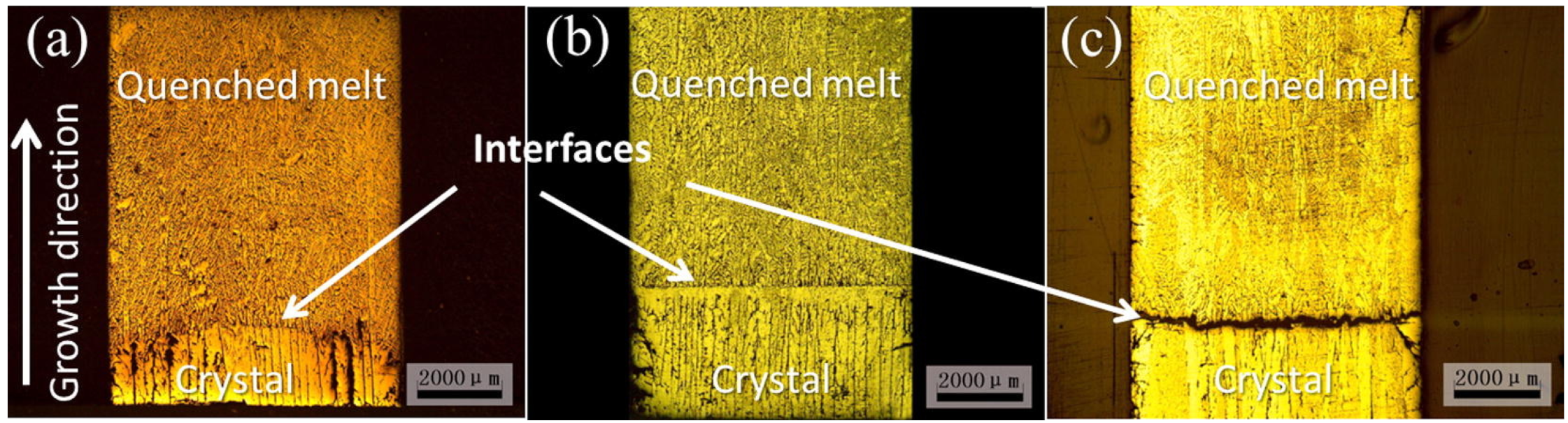
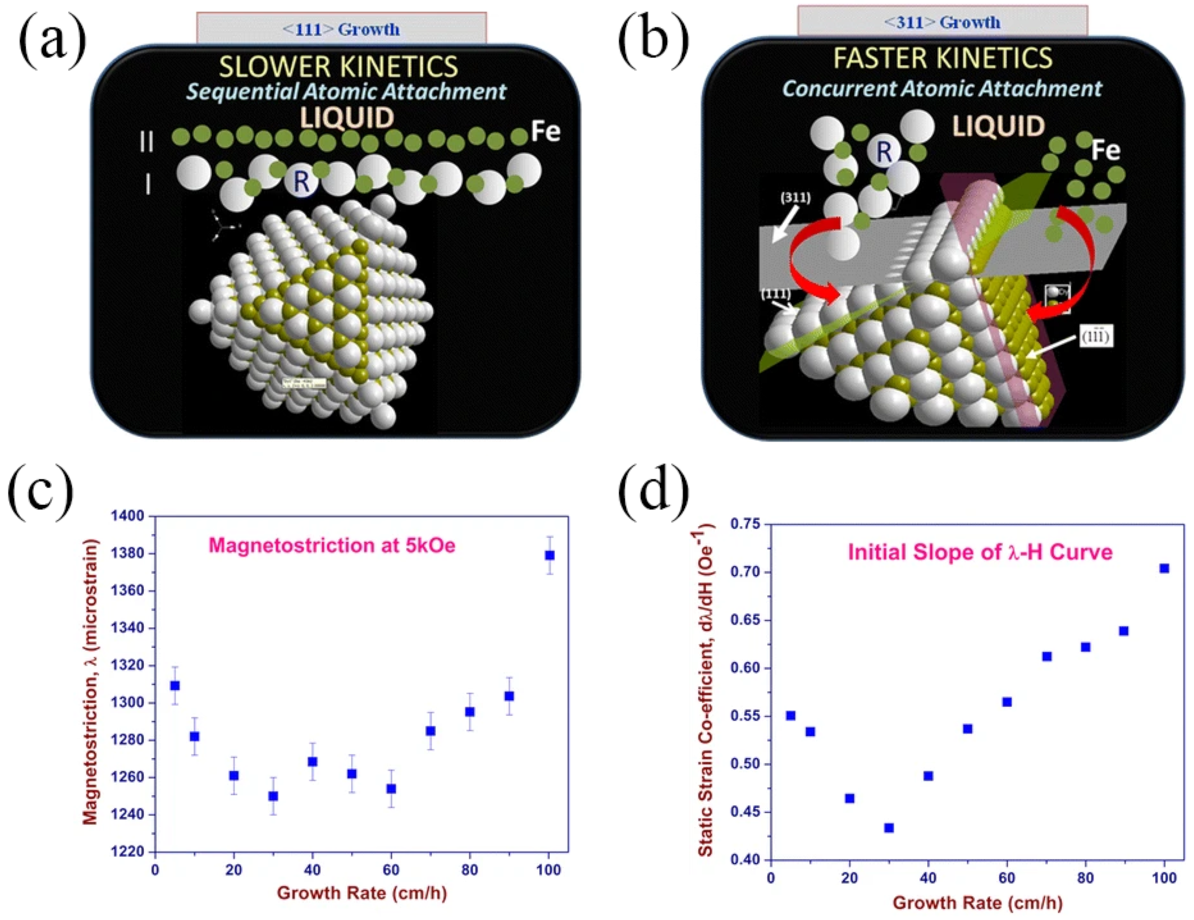
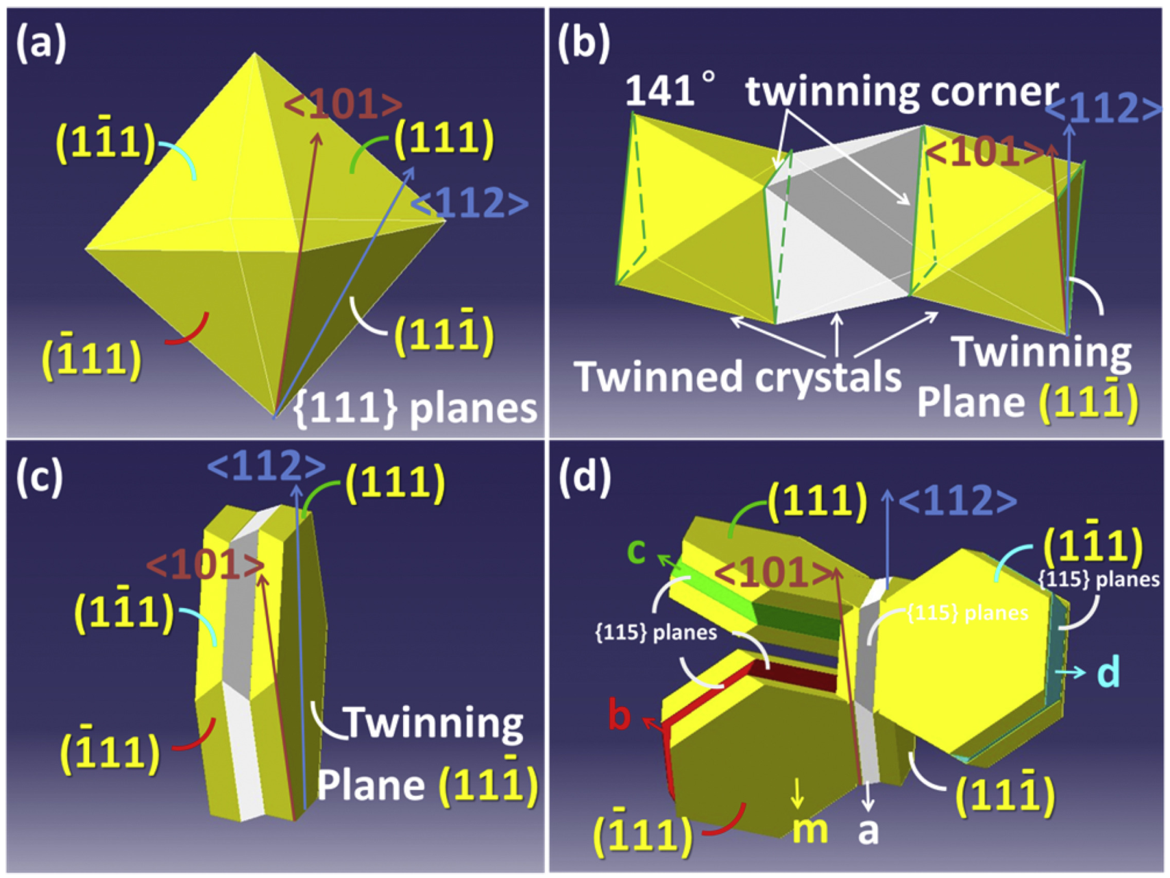
2.1. Grain Growth and Orientation Control during Directional Solidification Process

The growth process of crystals in directional solidification directly affects the final orientation of grains. Therefore, it is necessary to understand the crystal growth mechanism and orientation selection mechanism during this process; for example, the solid–liquid interface morphology and atomic adhesion kinetics should be researched.
The solid–liquid interface morphology plays a key role in single-crystal growth. By controlling the zone-melting length using a modified optical zone-melting method, Kang et al. [19] obtained three forms of solid–liquid interface morphologies, namely, convex, flat and concave interfaces, as shown in Figure 1. They successfully prepared an <110> axial oriented Tb-Dy-Fe twinned single crystal without radial composition segregation. Although the convex interface was conducive to single-crystal growth, it would produce radial component segregation; that is, the shape of the solid–liquid interface could affect the radial component distribution. By establishing their theoretical models, the effects of the temperature gradient, growth rate and zone-melting length on radial component segregation were qualitatively described.
Generally, solidification parameters, such as the temperature gradient and solidification rate, influence the evolution of texture during the directional solidification process. By comparing the texture at different distances from the onset of solidification, Palit et al. [20] found that the transition in the preferred growth direction from <110> to <112> occurred through intermediate <123> texture components. Furthermore, plane-front solidification morphology and irregular peritectic coupled growth were observed in a wide range of solidification rates (5–80 cm/h), while the preferred direction changed from <311> to <110> to <112> at 5–100 cm/h solidification rates [21]. The {111} planes in Figure 2a were composed of two different types of atomic layers, in which one layer was all Fe, which increased the obstacle of atomic arrangement in the growth process. At the same time, the {311} planes could be attached to the two {111} planes, as shown in Figure 2b. Therefore, although {111} planes had higher atomic bulk density, the preferred orientation at low solidification rates (5–30 cm/h) was <311>. In addition, the highest magnetostriction was achieved in the sample with a solidification rate of 100 cm/h due to the <112> preferred orientation, as shown in Figure 2c,d.
The growth twins of Tb-Dy-Fe alloys changed the crystal orientation, which was related to the crystal orientation of mirror symmetry [22]. Previous studies have shown that different solidification rates correspond to different solidification morphologies; that is, with the increase in the solidification rate, the preferred axial orientation changed from <101> to <112> and was then reoriented to <101> [23]. Recently, 3D spatial extension and transformation of the whole grain were asserted to be the key to interpreting the transformation of the preferred axial orientation. As a polyhedral material with a face-centered cubic structure, Tb-Dy-Fe alloy dendrites grow in the form of twin-related lamellae. In this case, when the crystal grows in a cellular form, the initial dendritic arms of the <110> axially oriented crystal have two extension directions, which will occupy more space and obtain preferential growth (Figure 3). Therefore, the transformation of the preferred axial orientation was explained by the different space-occupying capacities caused by the different morphological configurations for <101> and <112> axially oriented grains [24].

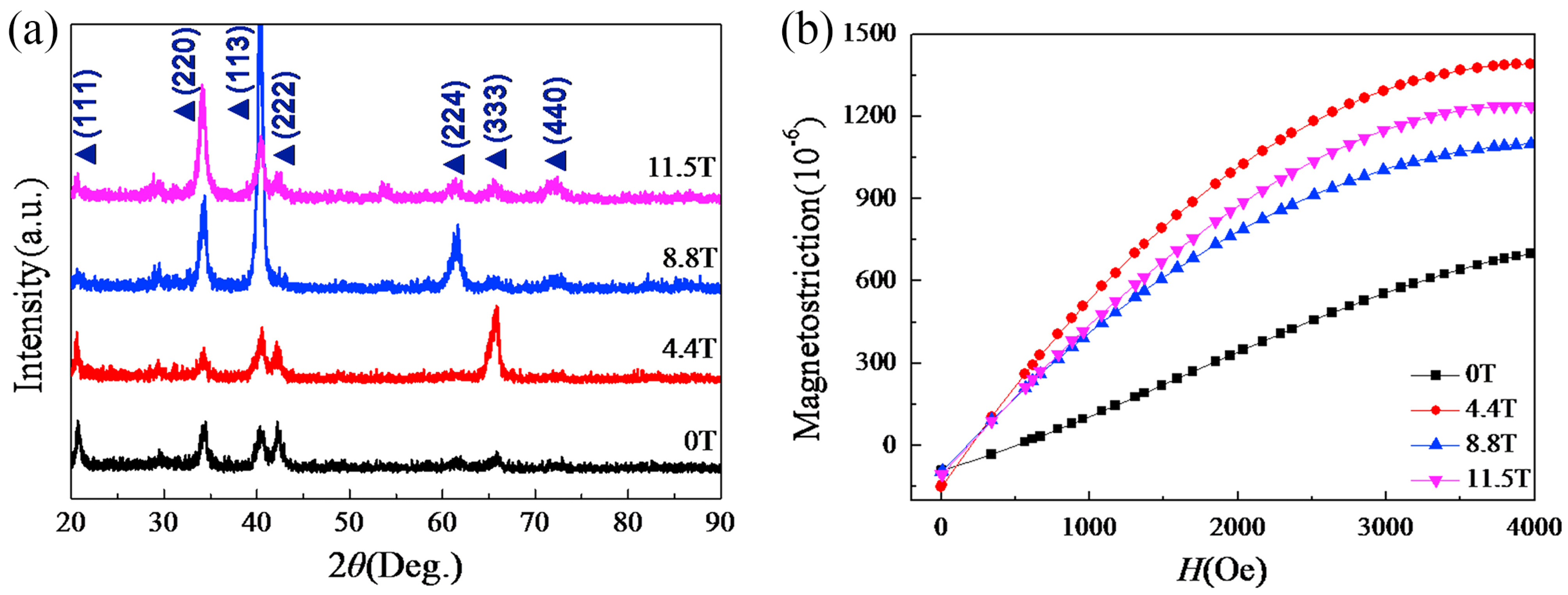
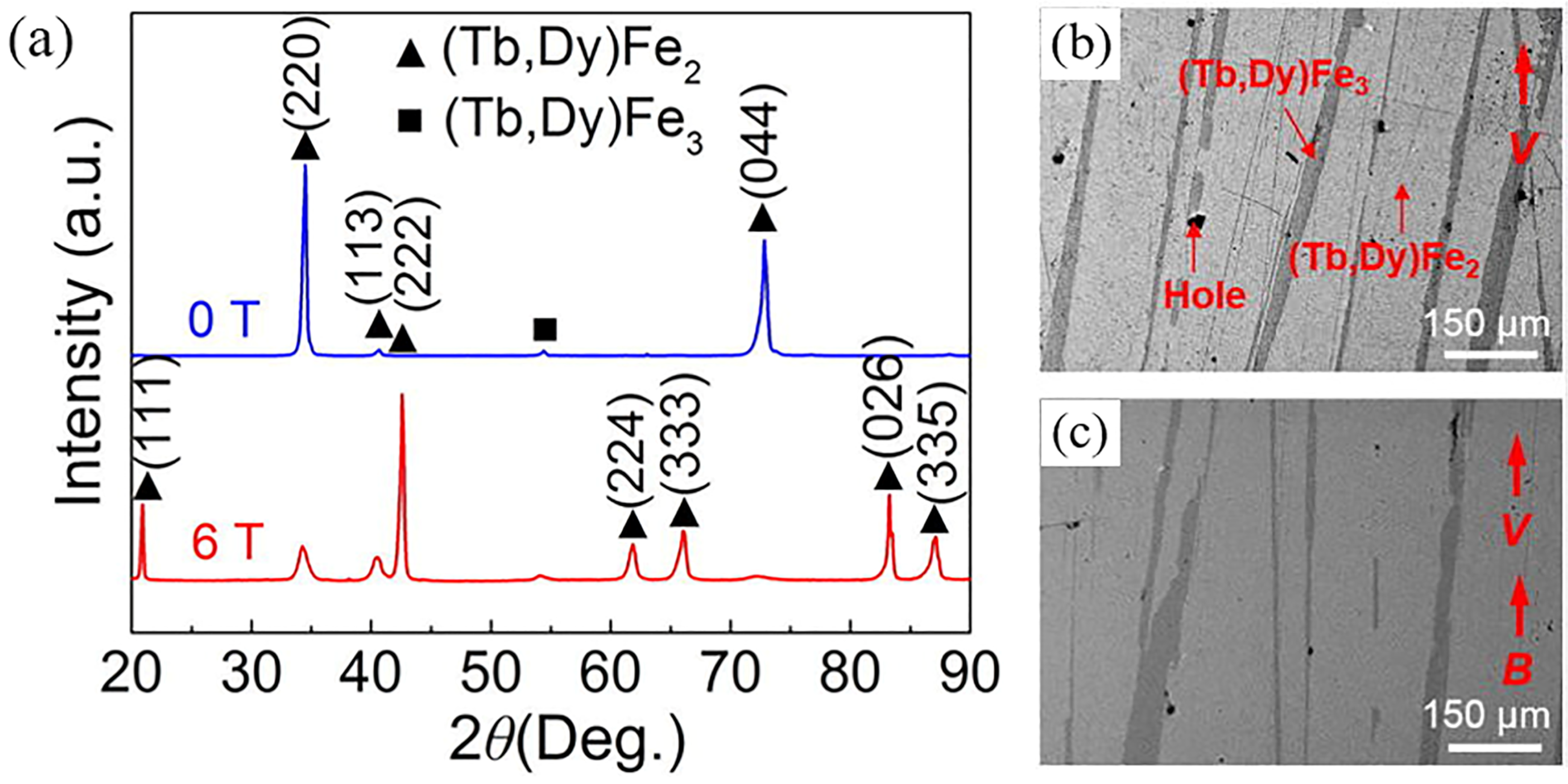
2.2. <111>-Oriented Tb-Dy-Fe Alloys Prepared by Directional Solidification in Magnetic Fields

Aiming to prepare Tb-Dy-Fe alloys with preferred orientation along <111> or close to <111>, researchers introduced a strong magnetic field to induce the crystal orientation in a specific direction during the directional solidification process. According to the relevant theory of crystal orientation induced by a magnetic field [25], if there is sufficient action time and rotation space, grains of materials with magnetocrystalline anisotropy will rotate and be oriented under the action of a strong magnetic field through Lorentz force, magnetic force and the magnetic moment of materials.
A high magnetic field in the horizontal direction was directly applied to the directional solidification process [26]. Liu et al. [27,28,29,30,31] obtained a higher <111> orientation and improved magnetostrictive properties by applying a constant magnetic field of 4.4 T during the solidification process of Tb0.27Dy0.73Fe1.95 alloy, as shown in Figure 4. In addition, the best contrast of the domain image and the widest magnetic domain were obtained in the sample prepared under a 4.4 T magnetic field [27]. The required magnetic field in the range of 4–10 T to achieve <111> orientation increased with the increase in the cooling rate [28].
Recently, researchers obtained both orientation and alignment along <111> by multiple magnetic field effects of the liquid phase and solid phase, as shown in Figure 5 [29,30]. In addition, magnetostrictive and mechanical properties were increased by adjusting the content, morphology and distribution of the (Tb, Dy)Fe3 phase and WSP by coupling directional solidification with a high magnetic field [31].
Furthermore, when a gradient magnetic field strongly dependent on the cooling rate was applied during cooling and solidification, magnetic gradient Tb0.27Dy0.73Fe1.95 alloy with gradient magnetostriction and saturation magnetization was obtained, as shown in Figure 6, which was attributed to the increase in the gradient of the orientation degree [32,33,34].

3. Effects of Substitute Elements on Magnetostriction of Tb-Dy-Fe Alloys

Cubic RFe2 compounds usually have large magnetostriction at room temperature, but their magnetocrystalline anisotropy is also large. In this case, a strong external magnetic field is frequently required to achieve high performance in practical applications, which hinders the application of magnetostrictive RFe2 materials. Initially, aiming to reduce magnetocrystalline anisotropy as well as maintain large magnetostriction, pseudobinary RR′Fe2 compounds with an anisotropy compensation function were developed, that is, by alloying RFe2 compounds with the same magnetostriction symbol but opposite anisotropy symbol. Furthermore, with a Laves phase structure, the magnetic properties of this alloy can be easily changed by various substitutions in rare-earth and 3d transition-metal sublattices.

3.1. Alloy System Containing Other Rare-Earth Elements
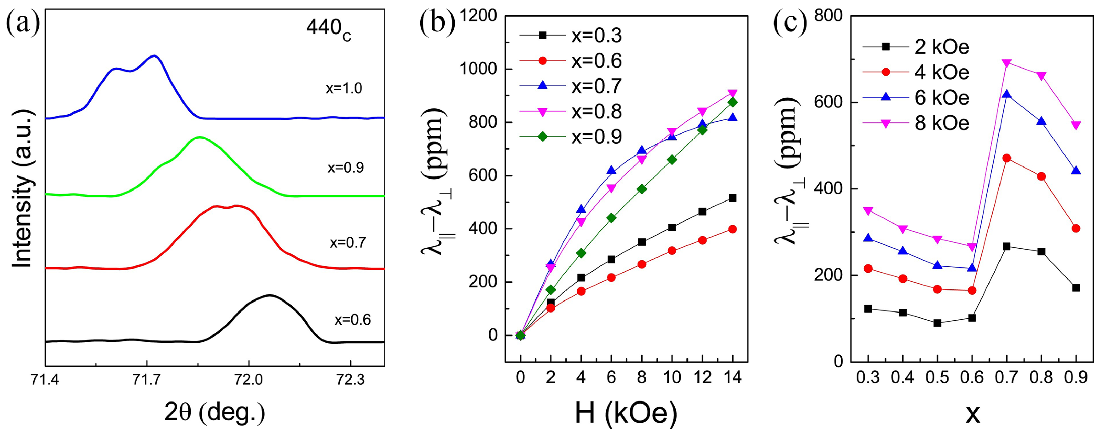
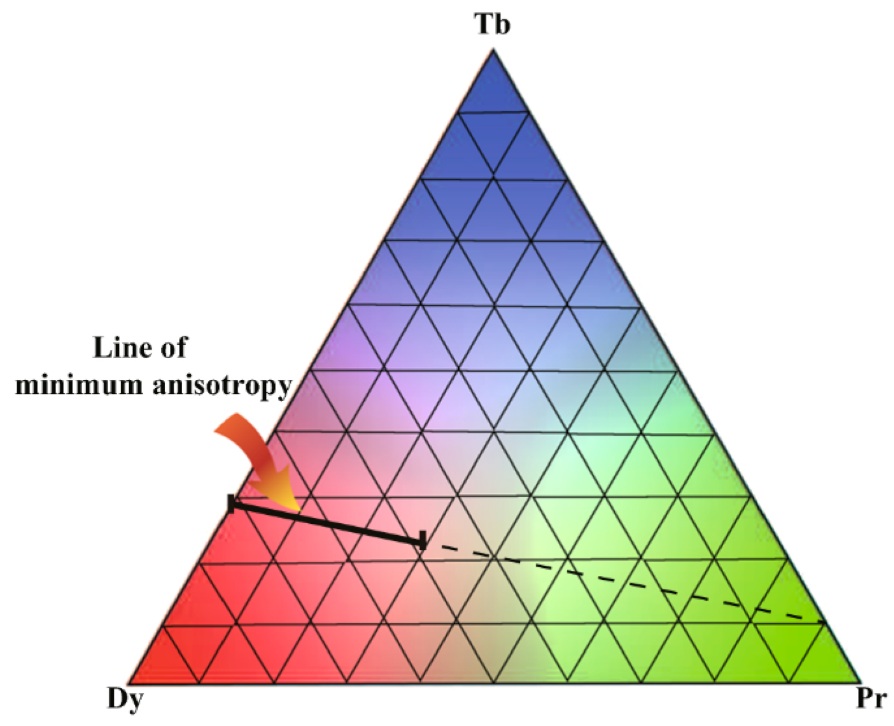
The introduction of the third rare-earth element can provide additional degrees of freedom for the (Tb,Dy)Fe2 system, minimizing the first-order anisotropy constant (K1) and the second-order anisotropy constant (K2), which is considered as an approach to improve the magnetostriction of Tb-Dy-Fe alloys.

3.1.1. Pr

PrFe2 has a very high magnetostrictive coefficient (about 5600 ppm at 0 k), and the high Pr content is also conducive to anisotropic compensation. However, Tb1−xPrxFe2 is a noncubic phase when the Pr content exceeds 20% due to the large Pr3+ radius, while high Pr content is conducive to anisotropic compensation [13]. During the last years, some studies have confirmed that (Tb, Pr, Dy) Fe2 series compounds are an anisotropic compensation system [35,36,37].
One way to improve the performance of the (Tb, Pr, Dy)Fe2 system is to replace Fe by adding Co, B and other elements. For instance, (Tb0.7Dy0.3)0.7Pr0.3(Fe1−xCox)1.85 (0 ≤ x ≤ 0.6) was composed of a MgCu2-type C15 cubic Laves phase, with a small amount of a PuNi3-type phase and rare-earth-rich phase [11]. The second phase of Dy1−x(Tb0.2Pr0.8)xFe1.93 (0 ≤ x ≤ 0.5) obtained by atmospheric pressure annealing appeared when x exceeded 0.3 [37]. Shi et al. successively synthesized PrxTb1−xFe1.9 (0 ≤ x ≤ 1) [38], Pr(Fe1−xCox)1.9 (0 ≤ x ≤ 0.5) [39], Dy1−xPrxFe1.9 (0 ≤ x ≤ 1) [40] and Pr1−xDyx(Fe0.8Co0.2)1.93 (x = 0.00, 0.05, 0.10, 0.20 and 0.30) [36] single cubic Laves compounds by high-pressure annealing. The magnetostriction of Pr0.95Dy0.05(Fe0.8Co0.2)1.93 alloy at 3kOe was 648 ppm, which is twice that of Tb0.2Dy0.58Pr0.22(Fe0.9B0.1)1.93 (about 300 ppm) [35].
The 440C XRD profiles and magnetostriction of (Tb0.2Pr0.8)xDy1−xFe1.93 (x = 0.00, 0.05, 0.10, 0.20 and 0.30) single Laves phase compounds synthesized by high-pressure annealing are shown in Figure 7 [41]. Based on the consideration of anisotropy compensation and thermodynamic energy flattening, a rare-earth sublattice was designed, and the ternary composition phase diagram and the minimum anisotropy composition are shown in Figure 8 [42].

3.1.2. Nd

Similar to Pr, many studies [43,44,45,46,47,48,49,50,51,52] have shown that the appropriate replacement of heavy rare-earth Tb and Dy with light rare-earth Nd is an effective approach to decrease magnetocrystalline anisotropy and improve magnetostriction. For example, the Tb0.4Dy0.5Nd0.1Fe1.93 compound possessed the large magnetostriction value of 1300 ppm at 5 kOe [47]. Pan et al. [45,48] obtained good magnetoelasticity in Tb0.3Dy0.6Nd0.1(Fe0.8Co0.2)1.93 by improving the annealing process.
Tb0.2Nd0.8(Fe0.8Co0.2)1.9 ribbons with high Nd content were prepared by melt spinning and low-temperature annealing, which provided another effective method for the synthesis of a C15 cubic Laves phase structure with high Nd content [49]. The results indicated that a higher solidification rate is conducive to the elimination of the (Tb, Nd)Fe3 phase. A single cubic Laves phase with a <111> easy magnetization direction at room temperature was obtained at 45 m/s runner speed and 773 K annealing temperature [50]. Subsequently, a series of Tb0.2Nd0.8(Fe1−xCox)1.9 (0 ≤ x ≤ 0.4) compounds were fabricated by rapid melt quenching in order to study the effects of Co substitution for Fe. It was found that the lattice parameter decreased with increasing x, and the (λ) of ribbons with x = 0.1–0.2 at 10 kOe was 306 ppm and 321 ppm, respectively [51]. That is, an appropriate amount of Co instead of Fe could promote the formation of a single Laves phase and improve the magnetostrictive properties of Tb0.2Nd0.8(Fe1−xCox)1.9 ribbons.
Recently, the spin configuration phase diagram (Figure 9a) of Tb0.27Dy0.73−xNdxFe2 (0 ≤ x ≤ 0.4) was designed based on the experimental results of magnetization with varying temperature, magnetic susceptibility and XRD analysis [52]. In this case, it was found that the Curie temperature, spin reorientation temperature, saturation magnetization and magnetostriction (Figure 9b) of the Tb0.27Dy0.73−xNdxFe2 compound decreased with the increase in Nd concentration. Moreover, a value of λ111 = 1700 ppm in the Tb0.27Dy0.63Nd0.1Fe2 Laves phase compound was obtained by high-pressure annealing.

3.1.3. Ho

Substituting a small amount of Ho for Tb and Dy in Tb0.3Dy0.7Fe2 can significantly decrease anisotropy and hysteresis loss [53]. Moreover, the addition of Ho also narrowed the temperature range between the liquidus temperature and the peritectic temperature, which was beneficial for reducing the pre-peritectic of the (Tb, Dy, Ho) Fe3 phase. Tb0.26Dy0.49Ho0.25Fe1.9 had both large magnetostriction and small hysteresis under a low magnetic field. Furthermore, it has also been found that magnetic annealing effectively increases magnetostriction [54]. Figure 10 shows the anisotropic compensation effects of Ho and Pr in Tb0.1Ho0.9−xPrx(Fe0.8Co0.2)1.93 alloys and the effects of their components on the phase structure and magnetostriction [55].
Moreover, the addition of Ho reduced the saturated magnetic field (220 kA/m) and dynamic magnetic loss of Tb-Dy-Fe fiber composites [56], and the maximum magnetostriction of the Tb-Dy-Ho-Fe/epoxy composite was 695 ppm when the Ho content x = 0.31 [57].

3.2. Alloy System Containing Other Elements

In a system containing light rare-earth elements, an appropriate amount of Co instead of Fe promoted and stabilized the formation of the cubic Laves phase [51,58,59]. In addition, 20 at% Co instead of Fe was found to increase the Curie temperature and saturation magnetization and improve the magnetostriction of Tb0.2Nd0.8Fe1.9 ribbons [51]. Co substitution for Fe was able to extend the operating temperature range for Tb0.36Dy0.64Fe2 by increasing the Curie temperature (Tc) or decreasing the spin reorientation temperature (Tr) [60,61]. Recently, Yang et al. found a new “Griffiths-like transition” in Tb0.3Dy0.7(Co1−xFex)2 when x < 0.8 and suggested that its disappearance was due to the interaction between Fe and Co [62]. In addition, enhanced magnetostriction (818 ppm) and high Tc (707 K) were obtained at x = 0.8. Theoretically, the doping of transition metals modulated the exchange action between 3d-3d and 3d-4f atoms, and it is expected to improve the elastic energy and magnetostatic energy.
Based on the different effects of the addition of elements on properties, Wang et al. [59] divided different elements into two types: those that readily formed phases with rare-earth elements and those that readily formed phases with the enthalpy of mixing between atomic pairs. After adding Nb, Ti and V elements, the second phases NbFe2, Fe2Ti and FeV, respectively, were dispersed in the Tb-Dy-Fe matrix alloy, as shown in Figure 11, which can inhibit the formation of the harmful RFe3 phase.

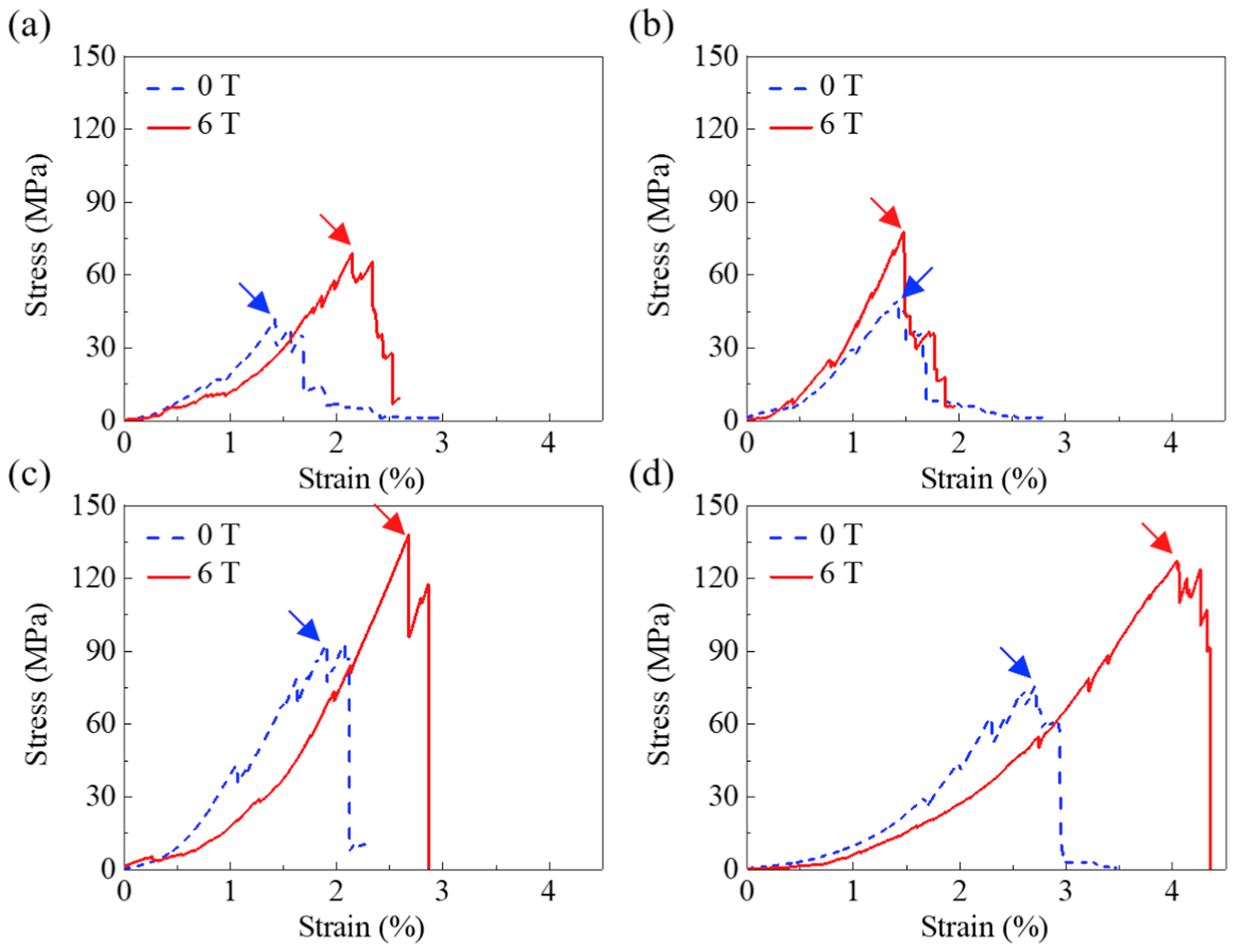
4. Mechanical Properties of Tb-Dy-Fe Alloys

The MgCu2-type RFe2 phase in the alloy provides a large magnetostrictive coefficient, but at the same time, the Laves phase is brittle and fractures easily at room temperature because of its topological close packing structure and lack of available slip system. There are also a large number of parallel acicular Widmanstatten precipitates (WSPs) in the Laves phase, that is, tiny (Tb, Dy)Fe3 phases [63,64]. The complex staggered distribution of WSPs and the lamellar distribution of (Tb, Dy)Fe3 phases in the matrix will adversely affect the mechanical properties.
As the Fe content decreases from a stoichiometric ratio of 2.0, the strength increases significantly, because the ductile rare-earth phase serving as the skeleton network delays crack propagation in the brittle matrix [65]. Heat treatment [6,66] can also improve the mechanical properties by controlling the dispersion and uniform distribution of the spherical rare-earth-rich phase.
In studies on alloying, the NbFe2 phase [67] and (Tb, Dy)Cu phase [68] were found to have the ability to prevent crack propagation, which was beneficial for the improvement of the mechanical properties of the Tb-Dy-Fe alloys. It was suggested that the existence of a soft phase in the alloy made the material exhibit inelastic strain under tensile or shear load. For instance, the soft (Tb, Dy)Cu phase played a key role in stopping or changing the direction of cracks, as shown in Figure 12. The addition of Cu increased the fracture toughness by 2–3 times, and the alloy with 1 at% Cu showed the best fracture toughness of 3.47 MPa·m1/2. With the addition of Nb, the fracture toughness was 1.5–5 times higher than that of Nb-free alloy.
Inspired by the ductility (Tb, Dy)Cu phase, the low-melting-point Dy-Cu alloy was introduced to the grain boundary phase of directionally solidified Tb0.3Dy0.7Fe1.95 alloy by grain boundary diffusion [69]. The results revealed that the magnetostrictive properties were maintained at 1021–1448 ppm, and the optimum bending strength was increased by nearly 2.6 times (Figure 13). The large magnetostriction was attributed to the matrix Laves phase structure and stable preferred orientation during the grain boundary diffusion process. In addition, the grain boundary phase was mainly composed of the ductile (Dy,Tb)Cu phase, which can retard crack propagation and improve the mechanical strength of Tb0.3Dy0.7Fe1.95 alloy.
The content, morphology and distribution of the (Tb, Dy)Fe3 phase and WSP in Tb0.3Dy0.7Fe1.95 alloy can be controlled by the effect of a magnetic field on grain orientation and element diffusion during the solidification process [31]. When the angle between the (Tb, Dy)Fe3 phase and the grain growth direction was the smallest and the WSP content was low, the alloy had better mechanical properties. The application of a 6T magnetic field during the solidification process improved the mechanical properties of the alloy at the same growth rate, as shown in Figure 14.

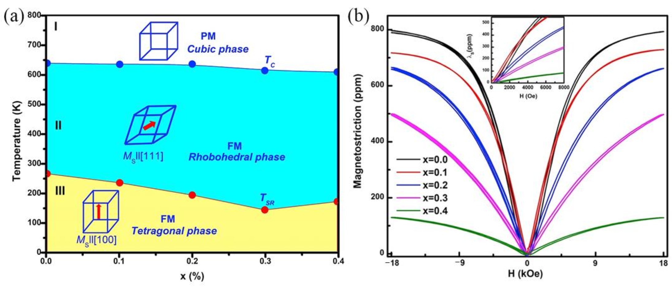
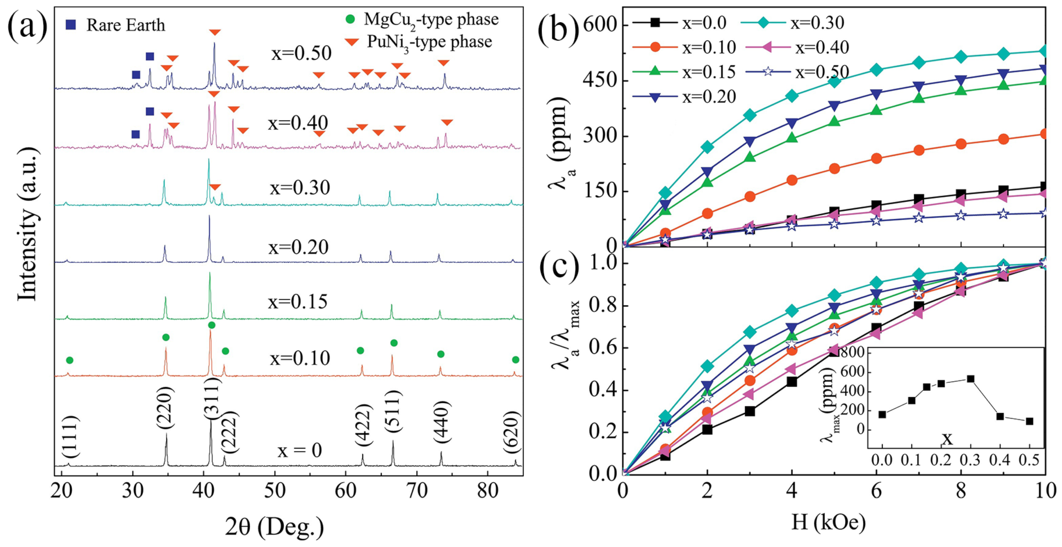
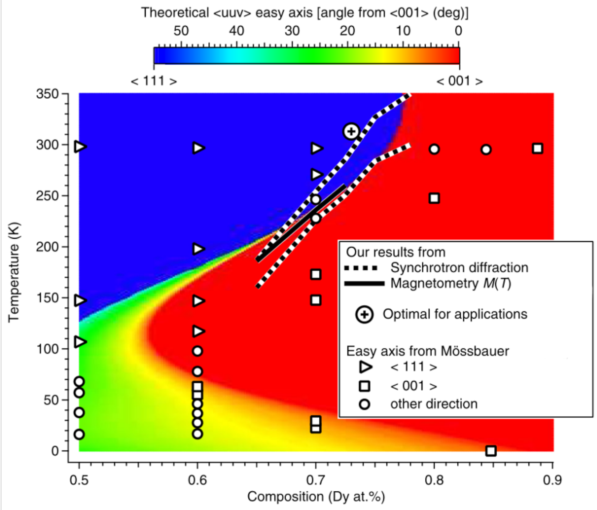
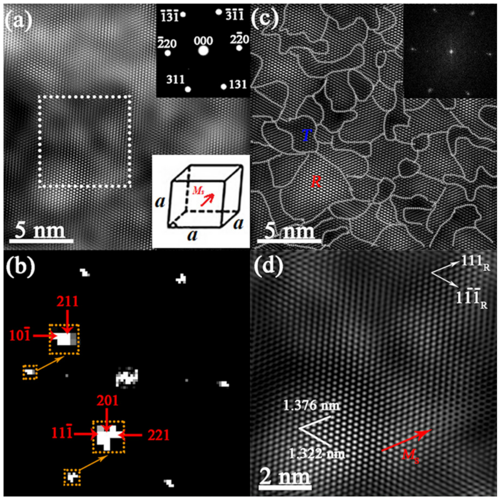
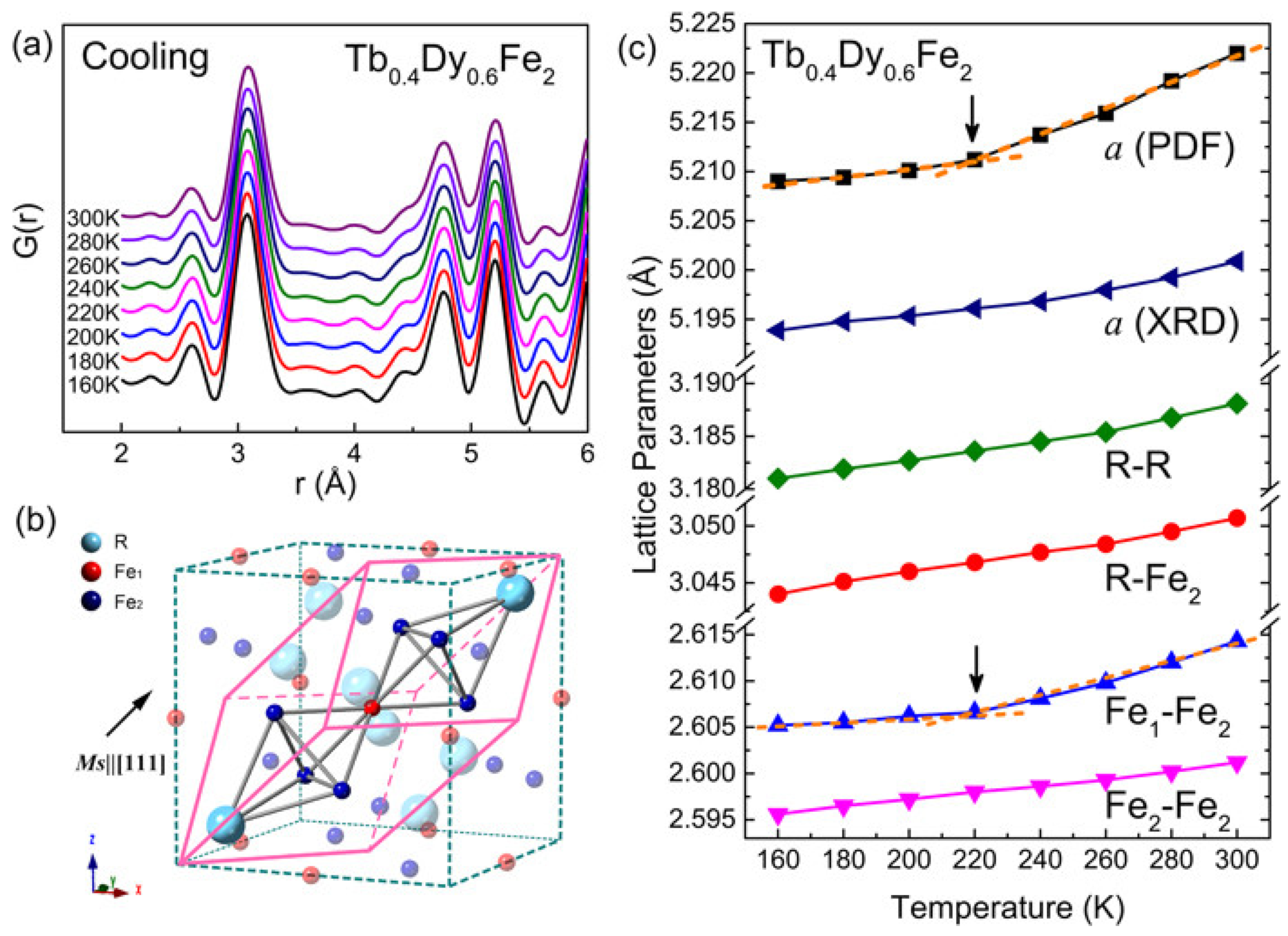
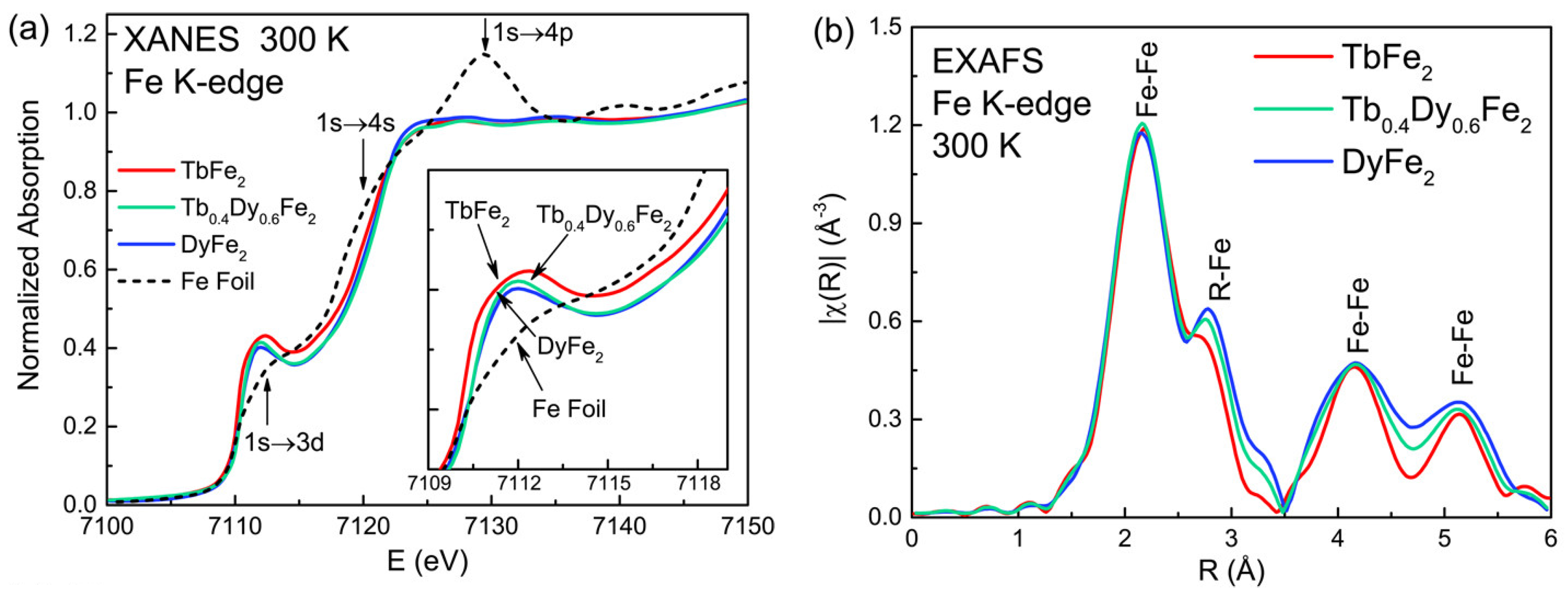
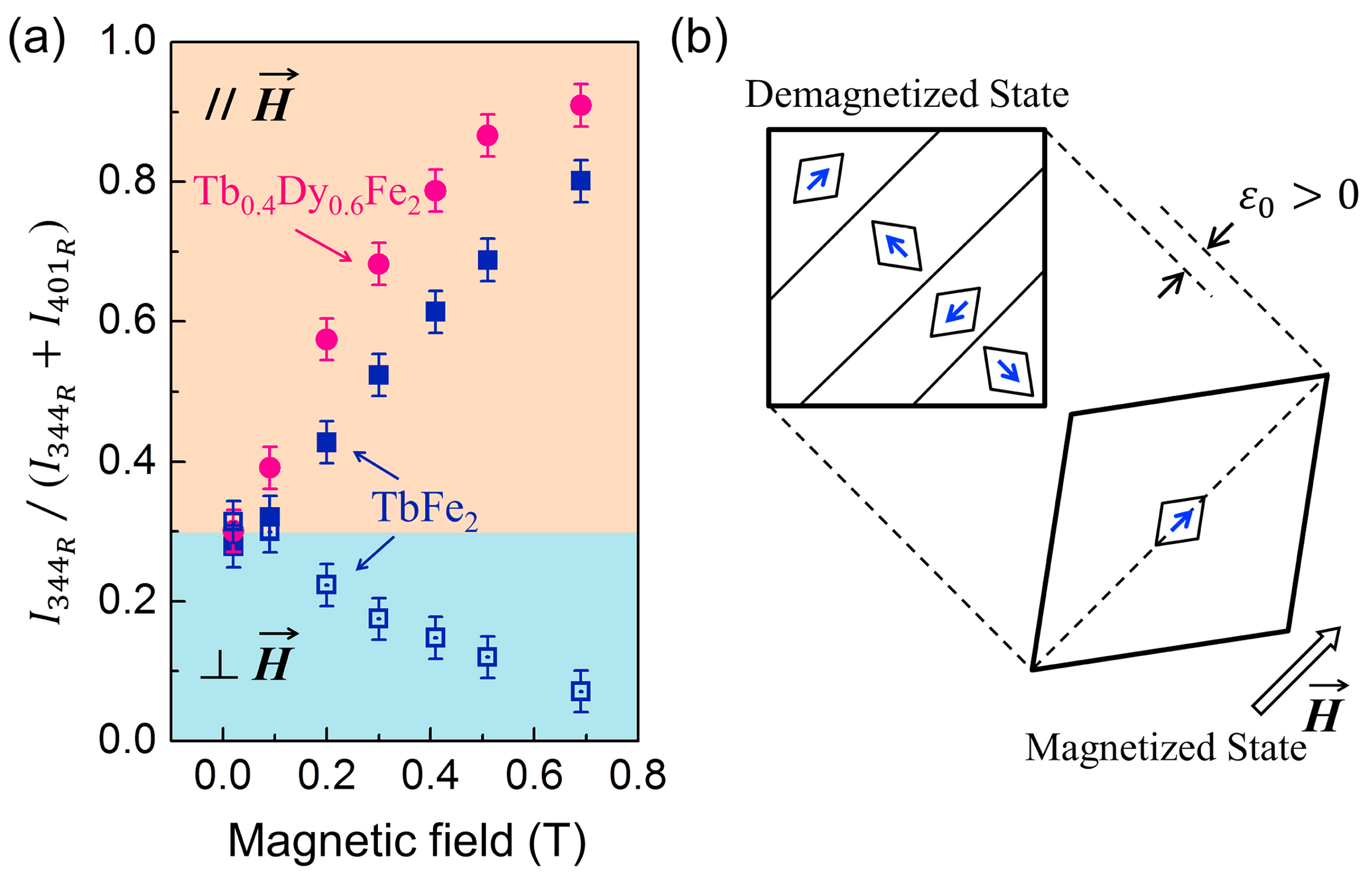
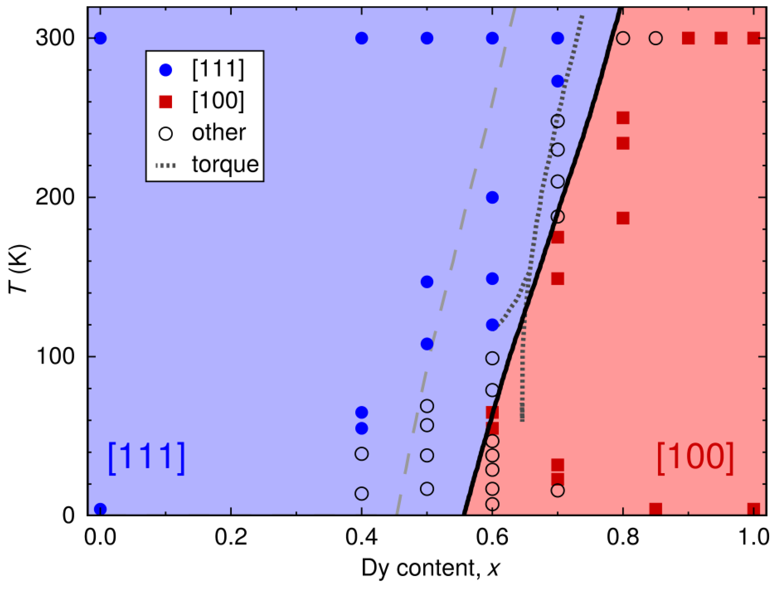
5. Structural Origin and Magnetic Morphotropic Phase Boundary (MPB) of Tb-Dy-Fe Alloys

To explore the more efficient Tb-Dy-Fe giant magnetostrictive material system, it is necessary to understand the basic principle of magnetostriction, rather than only having a phenomenological understanding. During the last years, with the development of high-resolution synchrotron radiation X-ray diffraction technology, it has been increasingly recognized that the ferromagnetic phase transition process is accompanied by a change in structural symmetry. Significantly, in-depth research of the magnetic morphotropic phase boundary (MPB) has been carried out. In previous research, the synchrotron radiation X-ray diffraction data of Tb0.3Dy0.7Fe2 at 300 K revealed that the {440} and {222} reflections were obviously split, reflecting rhombic symmetry and lattice stretching along the [111] direction. Structurally, this was the process of spin redirection from <001> to <111>, that is, the transition from the T phase with small lattice distortion along the <001> direction to the R phase with large lattice elongation along the <111> direction [70].
The phase diagram of Tb1−xDyxFe2 (Figure 15) was obtained through magnetometry and synchrotron XRD experiments [71,72,73]. It indicates that ferromagnetic MPB is composed of two crystal structures of the parent compounds TbFe2 and DyFe2, with a broadening MPB width at higher temperatures. Furthermore, a simulation based on the energy model demonstrated that the exchange energy narrowed the MPB region by affecting the magnetic phase transition process. This could also be used to explain the above abnormal phenomenon [72]. The exchange interaction was weakened with the increase in temperature, which corresponded to the broadening of the MPB region. In particular, the best point of magnetomechanical application was not centered on MPB but on one side of the rhombohedron. In addition, this local rhombohedral symmetry was further proved by high-resolution transmission electron microscopy. The local nanodomains of ferromagnetic rhombohedral and tetragonal phases coexist in Tb0.3Dy0.7Fe2, as shown in Figure 16 [74]. This is similar to the hierarchical nanodomain structure in ferroelectric materials.
The local stress environment generated by these randomly distributed tetragonal nanodomains in the rhombohedral matrix affected the interaction between Fe1 and Fe2 atoms and caused anomalies in the lattice, as shown in Figure 17 [18]. The weak Fe1-Fe2 bond was sensitive to the environment, which played an important role in the lattice characteristics of the rhombohedral phase. As a result, the lattice became more orderly with the increase in Dy and more stable Dy-rich phase, which was confirmed by X-ray absorption spectroscopy (XAS) techniques (Figure 18) [18].
These studies also enriched the understanding of the magnetic structure and the origin of large magnetostriction of Tb-Dy-Fe alloys. In detail, the maximum magnetostriction was related to the transition from the T phase with a smaller lattice along the <001> direction to the R phase with larger lattice elongation along the <111> direction.
It was proposed that the change in the magnetization direction under the action of an external magnetic field could be realized by field-preferred domain growth, which could contribute to explaining large magnetostriction in the low field [75]. The comparison of the diffraction peak intensity of TbFe2 and Tb0.4Dy0.6Fe2 compounds is shown in Figure 19. This magnetostriction of Tb0.4Dy0.6Fe2 was considered to be related to the reduction in rhombohedral distortion caused by replacing Tb by Dy, resulting in field-induced domain conversion, which was more sensitive to the external field [75].
The domain structure and transition near ferromagnetic MPB are also of great significance to understanding the large magnetostriction for Tb-Dy-Fe alloys. The micro-mechanism of domain strain behavior near ferromagnetic MPB was intuitively illustrated by the phase-field method, combining micromagnetic and micro-elastic theory. This large magnetostrictive strain was considered to be due to the low-energy rotation path of the local magnetization vector in the phase coexistence region. In particular, the tetragonal phase as the intermediate phase provided a low-energy rotation channel for the diamond phase domain from other directions to the external field direction [76,77]. Similar to ferroelectrics, it was believed that the flattening of thermodynamic energy should lead to the sensitive response of the ferromagnetic phase. Through the introduction of Tb0.1Pr0.9 to Co-doped Tb0.27Dy0.73Fe2 alloy, Hu et al. explored the feasibility of this assumption through phase-field simulation [42]. They provided a feasible strategy for the design of an ultrasensitive magnetostrictive response with minor metastable orthorhombic phases as bridging domains, as shown in Figure 20.
The optimum Dy content of x = 0.73 at room temperature was verified in Tb1−xDyxFe2 by first-principles calculations [78]. Combining first-principles calculations with the crystal-field approach, the critical Dy concentration was 0.78, and the corresponding magnetostrictive coefficient λ111 was 2700 ppm. The calculated spin-orientation diagram reproduced the experimental results for the [111] and [100] easy directions, as shown in Figure 21.

6. Progress on Tb-Dy-Fe Giant Magnetostrictive Composites

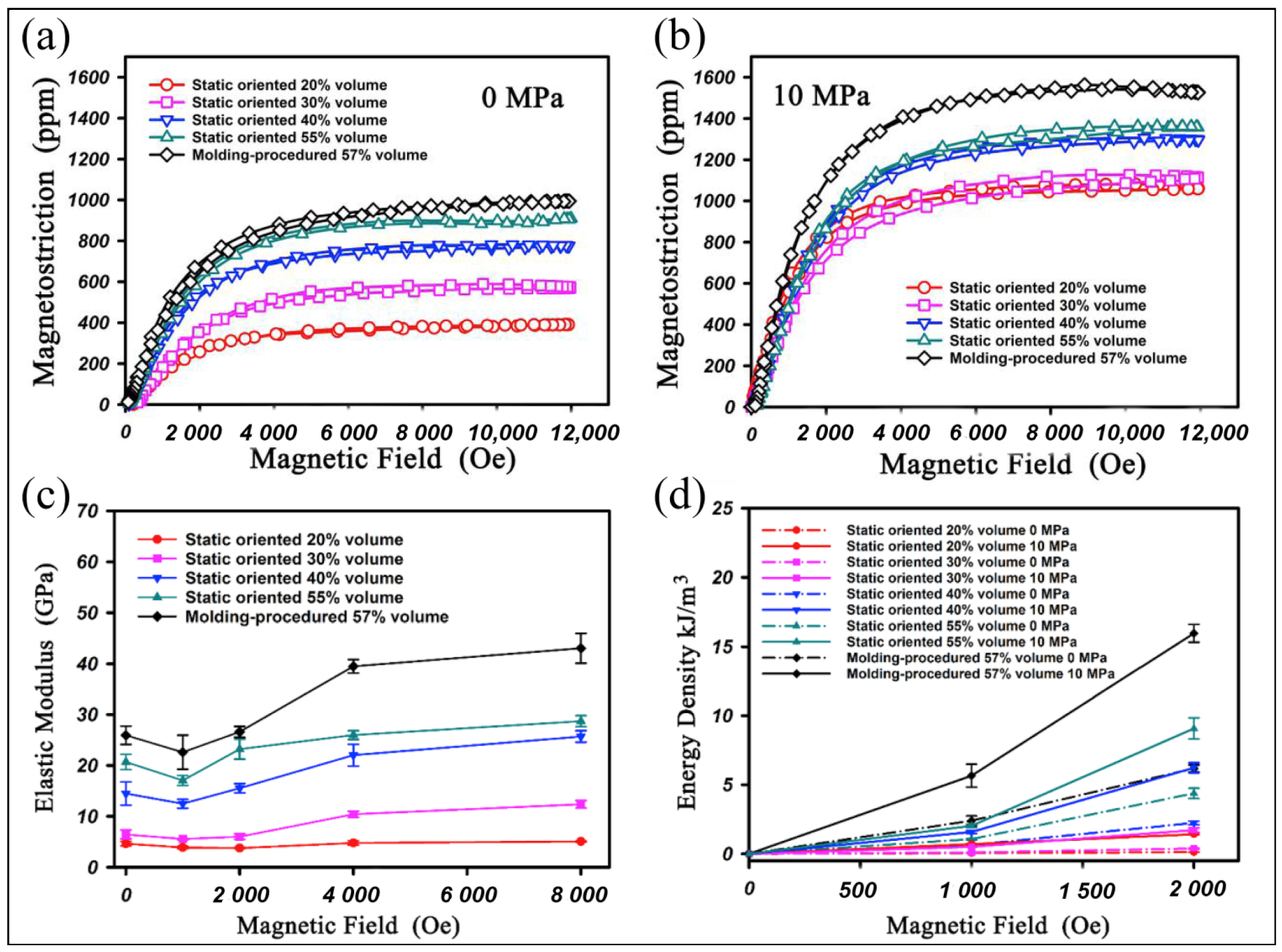
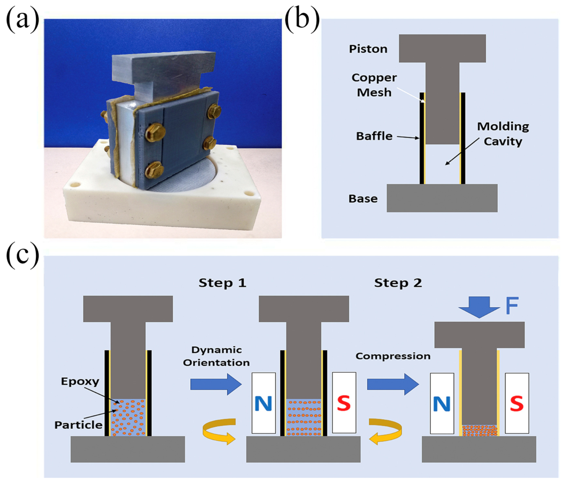
6.1. Polymer-Banded Tb-Dy-Fe Composite

Based on the requirements of device design, in recent years, some research has focused on giant magnetostrictive polymer composites (GMPCs) with high resistivity, a wide frequency response range and ease of formability. In a GMPC, Tb-Dy-Fe alloy particles were banded in the resin matrix in the form of particles or fibers. Tb-Dy-Fe alloy particles could be randomly dispersed (0–3 type) or arranged in a chain (1–3 type or pseudo-1–3 type) by applying different preparation methods [79]. The size, volume fraction and crystallographic orientation [80,81] of Tb-Dy-Fe alloy particles, as well as the bond strength [82] between the matrix and particles, will affect the magnetostrictive properties of the composite. After compounding, the eddy current was greatly reduced [83], which was conducive to the improvement of dynamic properties, and the mechanical properties were also greatly improved. The main characteristics of GMPCs of several Tb-Dy-Fe systems reported in the literature are summarized in Table 1.
Recently, GMPCs with a layered structure were prepared by dynamic orientation in an oscillating magnetic field [89]. Jiang et al. [87] further obtained a Tb-Dy-Fe/epoxy particle composite with a high alloy particle volume fraction (57%) and high saturation magnetostriction (1500 ppm) by using a two-step dynamic orientation method, as shown in Figure 22b, and the energy density shown in Figure 22d was markedly improved. From Figure 23, it can be seen that the Tb-Dy-Fe alloy particles were first dynamically magnetically oriented in the liquid epoxy resin and then molded and concentrated in the horizontal magnetic field to remove the excess resin before curing. In addition, the defect-free matrix and anisotropic layered structure prepared by this method can effectively transfer the strain.

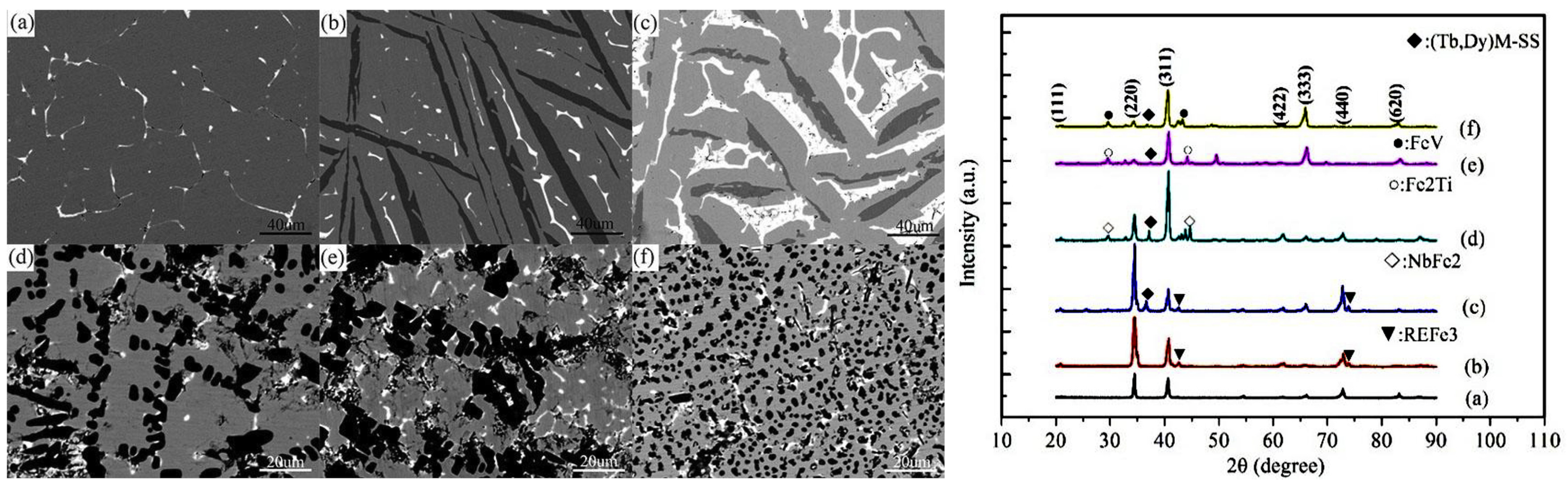
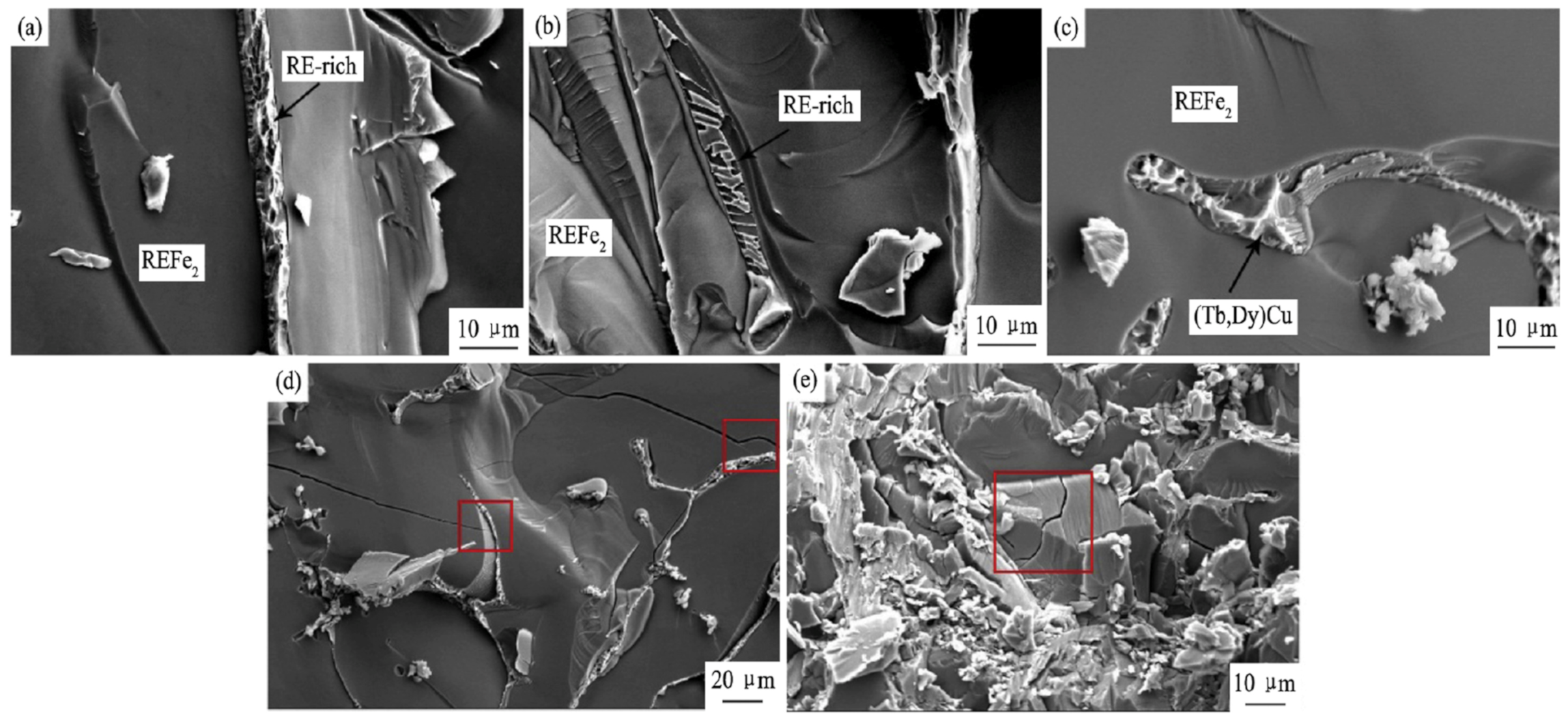
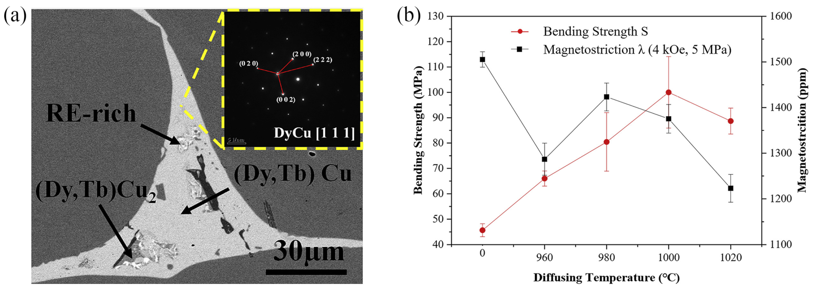
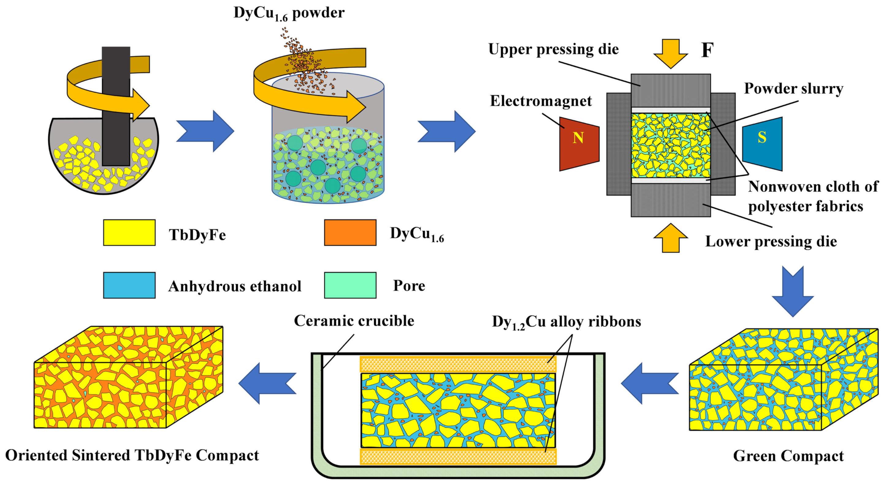
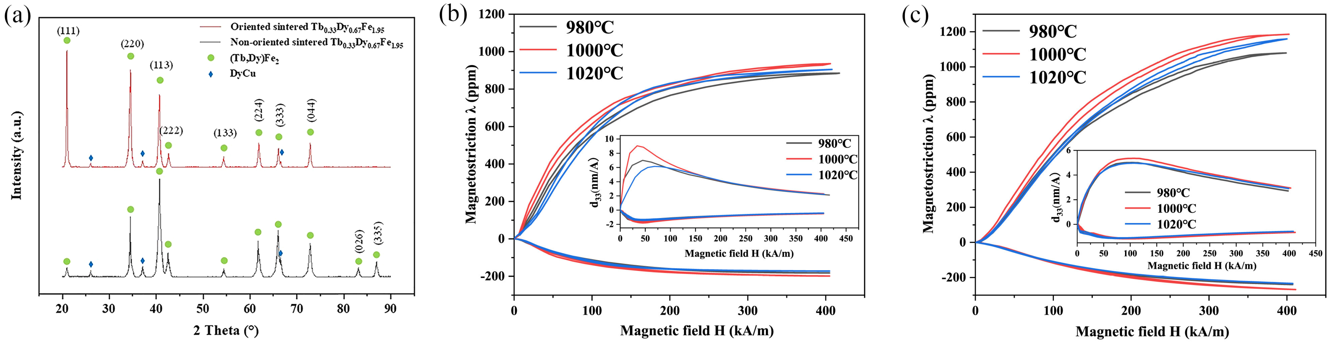
6.2. Sintered Tb-Dy-Fe Material Composited with Dy-Cu Alloys

For Tb-Dy-Fe composites with polymers, a high orientation degree and a higher content of particles in the composites cannot be achieved simultaneously, which limits the further improvement of energy density.
Recently, a new approach was proposed by Zhou et al. [90], which combined powder metallurgy with the magnetic field orientation. As shown in Figure 24, the powder slurry prepared with Tb0.33Dy0.67Fe1.95 single-crystal particles and low-melting-point DyCu1.6 alloy powders was wet pressed and oriented by a magnetic field. Subsequently, the compacts covered by Dy1.2Cu alloy thin ribbons were sintered at 1000 °C for 2 h. In this case, the DyCu1.6 alloy powders acted as a “binder” to wet Tb0.33Dy0.67Fe1.95 particles and provided a liquid channel for subsequent diffusion of Dy1.2Cu alloy, leading to an increase in the relative sintering density. Furthermore, a higher Tb-Dy-Fe particle content of above 90% was obtained in the sintered composites. Consequently, the <111> orientation and high sintering density effectively enhanced magnetostriction, as shown in Figure 25. More importantly, a major improvement of mechanical properties, with 176 MPa in bending strength and 71.3 MPa in tensile strength, was realized. This was attributed to the ductile Dy-Cu intergranular phase distributed along grain boundaries and the semicoherent interface between the Dy-Cu grain boundary phase and the brittle (Tb,Dy)Fe2 matrix phase. The low-melting-point Dy-Cu phase was introduced as the new grain boundary phase to the Tb-Dy-Fe alloys using the sintering method, and the <111> orientation degree was improved by magnetic field orientation combined with the adjustment of the Tb/Dy ratio and particle morphology. As a result, high mechanical properties and high magnetostrictive properties were obtained in the sintered Tb-Dy-Fe/Dy-Cu composites. Mechanically, the bending strength, fracture toughness and tensile strength were respectively 3.67, 2.41 and 2.55 times those of the directionally solidified polycrystalline Tb-Dy-Fe alloy [90].

7. Progress in Application of Tb-Dy-Fe Alloys

7.1. Tb-Dy-Fe Giant Magnetostrictive Thin Film

The research of small-scale magnetic structures is closely related to the design of microdevices and has attracted extensive attention. Tb-Dy-Fe thin film has certain applications in microelectromechanical systems (MEMS), such as microactuators and force sensors, because of its high sensitivity and large strain.
It was reported that films grown at higher substrate temperature have the combination of out-of-plane magnetic anisotropy and in-plane magnetic anisotropy [91]. Panduranga et al. obtained high-quality magnetoelastic film using sputtered Terfenol-D film after substrate heating and annealing crystallization at 450 °C [92]. In addition, another key problem of small-scale Tb-Dy-Fe materials is oxidation. It was found that the composition ratio of rare-earth oxides can be determined by the anomalous X-ray scattering method [93].
The magnetic properties of the films obtained by magnetron sputtering were similar to those of bulk single-crystal materials [92]. The magnetic properties of the micropatterned films obtained by photolithography and argon etching had little change relative to the continuous films, which was considered to be related to the oxidative passivation of the sidewall, as well as the strong dipole pair ratio of 3μm MFM and the strong blue color in the 20μm PEEM image in Figure 26. The results showed that it has a pseudo-single domain structure [94].
It was reported that the bimaterial cantilever structure of the magnetostrictive film prepared by electrodeposition had a large magnetostrictive coefficient of about 1250 ppm under an 11 kOe magnetic field (Figure 27), and the energy density was able to reach 100–165 kJ/m3 [95]. In microdevices with a cantilever structure, a multilayer structure was generally used for better device performance. For instance, Tb-Dy-Fe/graphene/Tb-Dy-Fe multilayer film was used to replace the traditional three-layer Tb-Dy-Fe film in recent research, which resulted in a reduction in the dynamic response delay time.

7.2. Application in Microsensors and Other Devices

Magnetostrictive materials are usually used in actuators and sonar transducers. Recently, Tb-Dy-Fe materials were used in various high-sensitivity magnetostrictive sensors, such as current sensors [96,97], magnetic sensors [98] and torque sensors [99]. To explore its application, some researchers sputtered Tb-Dy-Fe film on a Fe-Co substrate, and the composite film was expected to be used in high-precision nondestructive testing [100]. In recent years, an application in wireless temperature measurement was developed, in which Terfenol-D was used to increase the temperature coefficient of resonant frequency [101].
A Tb-Dy-Fe magnetostrictive transducer combined with an optical fiber sensor is able to improve the accuracy of magnetic field detection. A series of high-precision magnetic field sensors were prepared by combining them with a fiber Bragg grating (FBG) sensor [102,103,104] and phase-shifted fiber Bragg grating (PS-FBG) [105]. The high-sensitivity response of the device was improved by the design of different systems. Feng et al. prepared a high-finesse fiber-optic extrinsic Fabry–Perot interferometer (EFPI)-based sensor, and its sensitivity was significantly improved based on the design of a mechanical amplification structure [106].

8. Summary and Prospects

Improvements in the directional solidification preparation process, such as directional solidification with a strong magnetic field, are effective ways to obtain better orientation for directionally solidified Tb-Dy-Fe alloys. Tb-Dy-Fe composites prepared by the resin bonding method or low-melting-point alloy sintering method are more based on the improvement of high-frequency application properties and mechanical properties. At present, through the improvement of composite methods such as dynamic magnetic field orientation, the volume fraction and properties of Tb-Dy-Fe alloy particles have been greatly improved. In order to achieve better practical value, we need to constantly explore Tb-Dy-Fe series alloys with large magnetostriction, high mechanical properties, low loss and low cost. It is worth mentioning that the Dy-Cu phase was introduced as a new grain boundary phase to Tb-Dy-Fe alloys by the sintering method, and the <111> orientation was improved by the magnetic field orientation combined with the adjustment of the Tb/Dy ratio and particle morphology. High mechanical and magnetostrictive properties were achieved in sintered Tb-Dy-Fe/Dy-Cu composites. Meanwhile, sintered composite materials based on the reconstruction of the grain boundary phase also provide new ideas for the development of Tb-Dy-Fe materials with excellent comprehensive properties, including high magnetostriction, high mechanical properties, high corrosion resistance and high resistivity.
The studies of phase structure and ferromagnetic MPB, combined with domain structure, phase-field simulation and first-principles calculations, are very helpful to deeply understand the magnetostriction origin of Tb-Dy-Fe alloys. At the same time, such studies also facilitate an understanding of the influence of element substitution or developing a new alloy system. However, the mechanism and theoretical system still need more in-depth research to provide further support.
The research progress on the application of Tb-Dy-Fe alloys is extensive, especially in microdevices and various high-sensitivity sensors based on Tb-Dy-Fe films. However, bulk Tb-Dy-Fe materials could play a crucial role in a broader field on the basis of the effective improvement of comprehensive properties.

Author Contributions

Conceptualization, Z.Y. and J.L.; methodology, Z.Y. and J.L.; validation, Z.Y. and J.L.; formal analysis, Z.Y. and J.L.; investigation, Z.Y. and J.L.; resources, Z.Y. and J.L.; data curation, Z.Y. and J.L.; writing—original draft preparation, Z.Y. and J.L.; writing—review and editing, Z.Y., J.L., Z.Z. and J.G.; visualization, Z.Y. and J.L.; supervision, J.L. and X.G.; project administration, X.G.; funding acquisition, X.B. and X.G. All authors have read and agreed to the published version of the manuscript.

Funding

This research was funded by the National Key R & D Program of China, grant number 2021YFB3501403; the State Key Laboratory for Advanced Metals and Materials, grant numbers 2017Z-11 and 2018Z-07; and Fundamental Research Funds for the Central Universities, grant numbers FRF-GF-17-B2, FRF-GF-19-028B and FRF-GF-20-23B.

Institutional Review Board Statement

Not applicable.

Informed Consent Statement

Not applicable.

Data Availability Statement

Data available in a publicly accessible repository.

Acknowledgments

This work is supported by the National Key R & D Program of China (grant no. 2021YFB3501403), the State Key Laboratory for Advanced Metals and Materials (2017Z-11, 2018Z-07), and the Fundamental Research Funds for the Central Universities (FRF-GF-17-B2, FRF-GF-19-028B, and FRF-GF-20-23B).

Conflicts of Interest

The authors declare no conflict of interest.

References

  1. Clark, A.E. Magnetic and Magnetoelastic Properties of Highly Magnetostrictive Rare Earth-Iron Laves Phase Compounds. AIP Conf. Proc. 1974, 18, 1015–1029. [Google Scholar] [CrossRef]
  2. Clark, A.; Crowder, D. High temperature magnetostriction of TbFe2 and Tb0.27Dy0.73Fe2. IEEE Trans. Magn. 1985, 21, 1945–1947. [Google Scholar] [CrossRef]
  3. Zhou, S.Z.; Gao, X.X. Magnetostrictive Materials; Metallurgical Industry Press: Beijing, China, 2017. [Google Scholar]
  4. Zhou, S.Z.; Zhao, Q.; Zhang, M.C.; Gao, X.X.; Wang, Z.C.; Shi, Z.H. Giant magnetostrictive materials of Tb-Dy-Fe alloy with [110] axial alignment. Prog. Nat. Sci. 1998, 6, 83–86. [Google Scholar]
  5. Ma, T.; Jiang, C.; Xiao, F.; Xu, H. Magnetostriction of Tb0.36Dy0.64(Fe1−xCox)2 (x = 0-0.20) <112>-oriented crystals. J. Alloys Compd. 2006, 414, 276–281. [Google Scholar] [CrossRef]
  6. Wu, W.; Zhang, M.C.; Gao, X.X.; Zhou, S.Z. Effect of two-steps heat treatment on the mechanical properties and magnetostriction of <110> oriented TbDyFe giant magnetostrictive material. J. Alloys Compd. 2006, 416, 256–260. [Google Scholar] [CrossRef]
  7. Ren, W.J.; Zhang, Z.D. Progress in bulk MgCu2-type rare-earth iron magnetostrictive compounds. Chin. Phys. B 2013, 22, 077507. [Google Scholar] [CrossRef]
  8. Liu, J.H.; Zhang, T.L.; Wang, J.M.; Jiang, C.B. Giant Magnetostrictive Materials and Their Applications. Mater. China 2012, 31, 1–12. [Google Scholar]
  9. Pan, Z.B.; Liu, J.J.; Liu, X.Y.; Wang, J.; Du, J.; Si, P.Z. Structural, magnetic and magnetostrictive properties of Laves-phase compounds TbxHo0.9−xNd0.1Fe1.93 (0 ≤ x ≤ 0.40). Mater. Chem. Phys. 2014, 148, 82–86. [Google Scholar] [CrossRef]
  10. Wun-Fogle, M.; Restorff, J.B.; Clark, A.E. Hysteresis and magnetostriction of TbxDyyHo1-x-yFe1.95 [112] dendritic rods. J. Appl. Phys. 1999, 85, 6253–6255. [Google Scholar] [CrossRef]
  11. Guo, Z.J.; Busbridge, S.C.; Wang, B.W.; Zhang, Z.D.; Zhao, X.G. Structure and magnetic and magnetostrictive properties of (Tb0.7Dy0.3)0.7Pr0.3(Fe1−xCox)1.85 (0 ≤ x ≤ 0.6). IEEE Trans. Magn. 2001, 37, 3025–3027. [Google Scholar] [CrossRef]
  12. Xu, L.H.; Jiang, C.B.; Xu, H.B. Magnetostriction and electrical resistivity of Si doped Tb0.3Dy0.7Fe1.95 oriented crystals. Appl. Phys. Lett. 2006, 89, 192507. [Google Scholar] [CrossRef]
  13. Clark, A.E. Chapter 7 Magnetostrictive Rare Earth-Fe2 Compounds. In Handbook of Ferromagnetic Materials; Elsevier: Amsterdam, The Netherlands, 1980; Volume 1, pp. 531–589. [Google Scholar]
  14. Yang, S.; Bao, H.X.; Zhou, C.; Wang, Y.; Ren, X.B.; Song, X.P.; Matsushita, Y.; Katsuya, Y.; Tanaka, M.; Kobayashi, K. ChemInform Abstract: Structural Changes Concurrent with Ferromagnetic Transition. Chin. Phys. B 2013, 22, 046101. [Google Scholar] [CrossRef]
  15. Wei, S.R.; Song, X.P.; Yang, S.; Deng, J.K.; Wang, Y. Monte Carlo Simulation on the Magnetization Rotation near Magnetic Morphotropic Phase Boundary; SPIE: Shenzhen, China, 2012; Volume 8409. [Google Scholar] [CrossRef]
  16. Yang, S.; Bao, H.; Chao, Z.; Yu, W.; Gao, J. Large Magnetostriction from Morphotropic Phase Boundary in Ferromagnets. Phys. Rev. Lett. 2010, 104, 197201. [Google Scholar] [CrossRef]
  17. Fohtung, E. Magnetostriction Fundamentals. In Encyclopedia of Smart Materials; Rensselaer Polytechnic Institute: Troy, NY, USA, 2022; pp. 130–133. [Google Scholar] [CrossRef]
  18. Chang, T.; Zhou, C.; Chang, K.; Wang, B.; Shi, Q.; Chen, K.; Chen, Y.-S.; Ren, Y.; Yang, S. Local structure study on magnetostrictive material Tb1−xDyxFe2. J. Appl. Phys. 2020, 127, 235102. [Google Scholar] [CrossRef]
  19. Kang, D.Z.; Liu, J.H.; Jiang, C.B.; Xu, H.B. Control of solid-liquid interface morphology and radial composition distribution: TbDyFe single crystal growth. J. Alloys Compd. 2015, 621, 331–338. [Google Scholar] [CrossRef]
  20. Palit, M.; Banumathy, S.; Singh, A.K.; Pandian, S.; Chattopadhyay, K. Crystallography of solid-liquid interface and evolution of texture during directional solidification of Tb0.3Dy0.7Fe1.95 alloy. Intermetallics 2011, 19, 357–368. [Google Scholar] [CrossRef]
  21. Palit, M.; Banumathy, S.; Singh, A.K.; Pandian, S.; Chattopadhyay, K. Orientation Selection and Microstructural Evolution in Directionally Solidified Tb0.3Dy0.7Fe1.95. Metall. Mater. Trans. A 2016, 47, 1729–1739. [Google Scholar] [CrossRef] [Green Version]
  22. Kang, D.Z.; Liu, J.H.; Jiang, C.B.; Xu, H.B. Correlation between Growth Twinning and Crystalline Reorientation of Faceted Growth Materials during Directional Solidification. Cryst. Growth Des. 2015, 15, 3092–3095. [Google Scholar] [CrossRef]
  23. Jiang, C.B.; Zhou, S.S.; Zhang, M.C.; Run, W. The preferred orientation, microstructure and magnetostriction in directionally solidified TbDyFe alloys. Acta Metall. Sin. 1998, 34, 164–170. [Google Scholar]
  24. Kang, D.Z.; Zhang, T.L.; Jiang, C.B.; Xu, H.B. Preferred orientation transition mechanism of faceted-growth materials with FCC structure: Competitive advantage depends on 3D microstructure morphologies. J. Alloys Compd. 2018, 741, 14–20. [Google Scholar] [CrossRef]
  25. Sun, Z.H.I.; Guo, M.; Vleugels, J.; Van der Biest, O.; Blanpain, B. Strong static magnetic field processing of metallic materials: A review. Curr. Opin. Solid State Mater. Sci. 2012, 16, 254–267. [Google Scholar] [CrossRef]
  26. Wang, J.; Fautrelle, Y.; Ren, Z.M.; Li, X.; Nguyen-Thi, H.; Mangelinck-Noel, N.; Salloum, A.; Zhong, Y.B.; Kaldre, I.; Bojarevics, A. Thermoelectric magnetic force acting on the solid during directional solidification under a static magnetic field. Appl. Phys. Lett. 2012, 101, 1331–1333. [Google Scholar]
  27. Gao, P.F.; Liu, T.; Dong, M.; Yuan, Y.; Wang, Q. Magnetic domain structure, crystal orientation, and magnetostriction of Tb0.27Dy0.73Fe1.95 solidified in various high magnetic fields. J. Magn. Magn. Mater. 2016, 401, 755–759. [Google Scholar] [CrossRef]
  28. Gao, P.F.; Liu, T.; Chai, S.W.; Dong, M.; Wang, Q. Influence of magnetic flux density and cooling rate on orientation behavior of Tb0.27Dy0.73Fe1.95 alloy during solidification process. Acta Phys. Sin. Chin. Ed. 2016, 65, 335–342. [Google Scholar] [CrossRef]
  29. Dong, S.L.; Liu, T.; Dong, M.; Guo, X.Y.; Yuan, S.; Wang, Q. Enhanced magnetostriction of Tb–Dy–Fe via simultaneous <111>-crystallographic orientation and -morphological alignment induced by directional solidification in high magnetic fields. Appl. Phys. Lett. 2020, 116, 053903. [Google Scholar] [CrossRef]
  30. Wang, Q.; Liu, T.; Wang, K.; Gao, P.F.; Liu, Y.; He, J.C. Progress on High Magnetic Field-Controlled Transport Phenomena and Their Effects on Solidification Microstructure. ISIJ Int. 2014, 54, 516–525. [Google Scholar] [CrossRef] [Green Version]
  31. Dong, M.; Liu, T.; Guo, X.Y.; Liu, Y.R.; Dong, S.L.; Wang, Q. Enhancement of mechanical properties of Tb0.27Dy0.73Fe1.95 alloy by directional solidification in high magnetic field. Mat. Sci. Eng. A Struct. 2020, 785, 139377. [Google Scholar] [CrossRef]
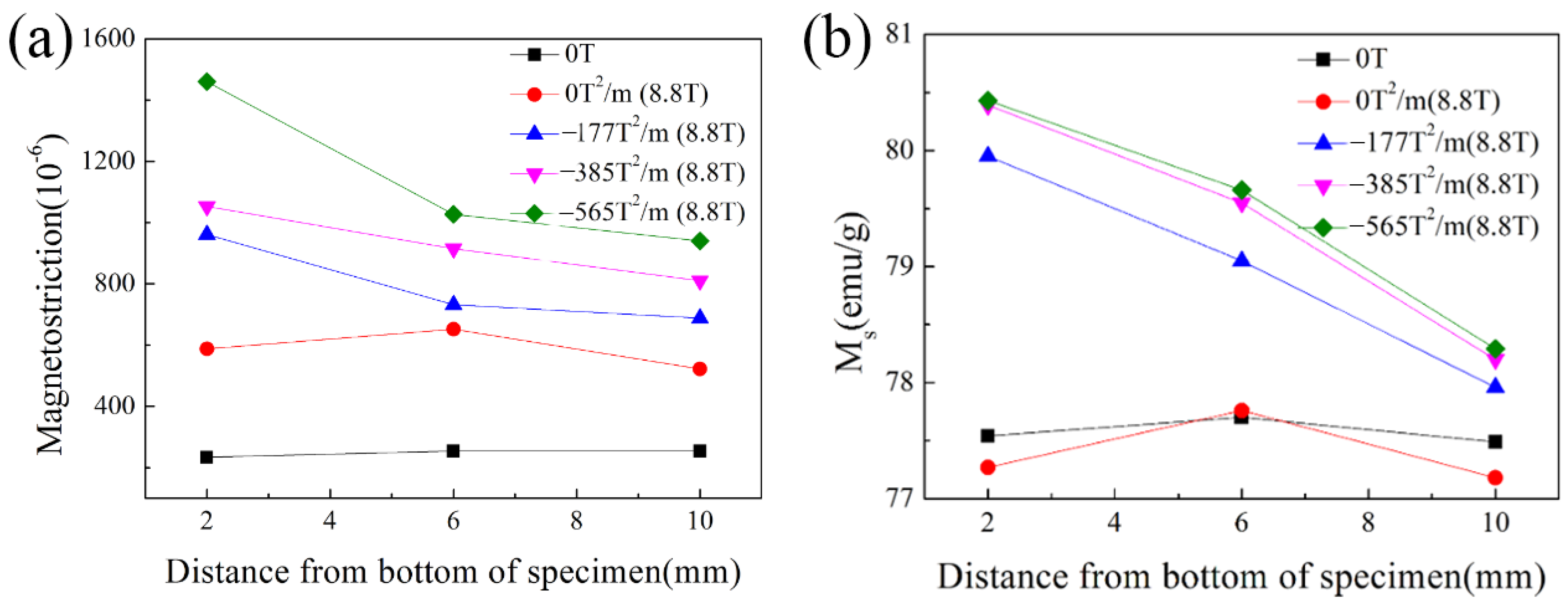
  32. Gao, P.F.; Liu, T.; Dong, M.; Yuan, Y.; Wang, K.; Wang, Q. Magnetostrictive gradient in Tb0.27Dy0.73Fe1.95 induced by high magnetic field gradient applied during solidification. Funct. Mater. Lett. 2016, 09, 1650003. [Google Scholar] [CrossRef]
  33. Gao, P.F. Evolution of Microstructure and Magnetostrictive Performance of Tb0.27Dy0.73Fe1.95 Alloy Solidified in High Magnetic Field Gradients. Ph.D. Dissertation, Northeastern University, Boston, MA, USA, 2015. [Google Scholar]
  34. Liu, T.; Gao, P.F.; Dong, M.; Xiao, Y.B.; Wang, Q. Effect of cooling rate on magnetostriction gradients of Tb0.27Dy0.73Fe1.95 alloys solidified in high magnetic field gradients. AIP Adv. 2016, 6, 056216. [Google Scholar] [CrossRef] [Green Version]
  35. Ren, W.J.; Liu, J.J.; Li, D.; Liu, W.; Zhao, X.G.; Zhang, Z.D. Direct experimental evidence for anisotropy compensation between Dy3+ and Pr3+ ions. Appl. Phys. Lett. 2006, 89, 122506. [Google Scholar] [CrossRef] [Green Version]
  36. Shi, Y.G.; Chen, Z.Y.; Wang, L.; Hu, C.C.; Pan, Q.; Shi, D.N. Synthesis and magnetostrictive properties of Pr1−xDyx(Fe0.8Co0.2)1.93cubic Laves compounds. AIP Adv. 2016, 6, 056207. [Google Scholar] [CrossRef] [Green Version]
  37. Zhang, G.B.; Zheng, W.G.; Cui, Y.; Shi, Y.G.; Shi, D.N. Structural, Magnetic, and Magentostrictive Properties of Dy1−x(Tb0.2Pr0.8)xFe1.93 (0 ≤ x ≤ 0.5) Compounds. J. Supercond. Novel Magn. 2017, 31, 2217–2220. [Google Scholar] [CrossRef]
  38. Shi, Y.G.; Tang, S.L.; Wang, R.L.; Su, H.L.; Han, Z.D.; Lv, L.Y.; Du, Y.W. High-pressure synthesis of giant magnetostrictive PrxTb1−xFe1.9 alloys. Appl. Phys. Lett. 2006, 89, 202503. [Google Scholar] [CrossRef]
  39. Shi, Y.G.; Tang, S.L.; Zhai, L.; Huang, H.B.; Wang, R.L.; Yu, J.Y.; Du, Y.W. Composition anisotropy compensation and magnetostriction in Pr(Fe1−xCox)1.9 (0 ≤ x ≤ 0.5) cubic Laves alloys. Appl. Phys. Lett. 2008, 92, 212507. [Google Scholar] [CrossRef]
  40. Shi, Y.G.; Tang, S.L.; Lv, L.Y.; Fan, J.Y. Magnetic and magnetostrictive properties in high-pressure synthesized Dy1−xPrxFe1.9 (0 ≤ x ≤ 1) cubic Laves alloys. J. Alloys Compd. 2010, 506, 533–536. [Google Scholar] [CrossRef]
  41. Zhang, G.B.; Liu, Y.D.; Kan, C.X.; Shi, Y.G.; Shi, D.N. Structure and magnetostriction in (Tb0.2Pr0.8)xDy1−xFe1.93 Laves compounds synthesised by high-pressure annealing. Mater. Res. Bull. 2019, 112, 174–177. [Google Scholar] [CrossRef]
  42. Hu, C.C.; Zhang, Z.; Cheng, X.X.; Huang, H.B.; Shi, Y.G.; Chen, L.Q. Ultrasensitive magnetostrictive responses at the pre-transitional rhombohedral side of ferromagnetic morphotropic phase boundary. J. Mater. Sci. 2020, 56, 1713–1729. [Google Scholar] [CrossRef]
  43. Hu, C.C.; Shi, Y.G.; Shi, D.N.; Zhou, X.G.; Fan, J.Y.; Lv, L.Y.; Tang, S.L. Optimization on magnetic transitions and magnetostriction in TbxDyyNdz(Fe0.9Co0.1)1.93 compounds. J. Appl. Phys. 2013, 114, 143906. [Google Scholar] [CrossRef]
  44. Liu, J.J.; Pan, Z.B.; Liu, X.Y.; Zhang, Z.R.; Song, X.H.; Ren, W.J. Large magnetostriction and direct experimental evidence for anisotropy compensation in Tb0.4−xNdxDy0.6(Fe0.8Co0.2)1.93 Laves compounds. Mater. Lett. 2014, 137, 274–276. [Google Scholar] [CrossRef]
  45. Yin, H.Y.; Liu, J.J.; Pan, Z.B.; Liu, X.Y.; Liu, X.C.; Liu, L.D.; Du, J.; Si, P.Z. Magnetostriction of TbxDy0.9−xNd0.1(Fe0.8Co0.2)1.93 compounds and their composites (0.20 ≤ x ≤ 0.60). J. Alloys Compd. 2014, 582, 583–587. [Google Scholar] [CrossRef]
  46. Shi, Y.G.; Tang, S.L.; Huang, Y.J.; Lv, L.Y.; Du, Y.W. Anisotropy compensation and magnetostriction in TbxNd1−xFe1.9 cubic Laves alloys. Appl. Phys. Lett. 2007, 90, 142515. [Google Scholar] [CrossRef]
  47. Jammalamadaka, S.N.; Markandeyulu, G.; Balasubramaniam, K. Magnetostriction and anisotropy compensation in TbxDy0.9−xNd0.1Fe1.93 (0.2 ≤ x ≤ 0.4). Appl. Phys. Lett. 2010, 97, 242502. [Google Scholar] [CrossRef]
  48. Pan, Z.B.; Liu, J.J.; Liu, X.Y.; Li, X.; Song, X.H.; Zhang, Z.R.; Ren, W.J. Structural, magnetic and magnetoelastic properties of Laves-phase Tb0.3Dy0.6Nd0.1(Fe1−xCox)1.93 compounds (0 ≤ x ≤ 0.40). Intermetallics 2015, 64, 1–5. [Google Scholar] [CrossRef]
  49. Chen, Z.Y.; Shi, Y.G.; Wang, L.; Pan, Q.; Li, H.F.; Shi, D.N. Structure and magnetic properties of melt-spun Tb0.2Nd0.8(Fe0.8Co0.2)1.9 compound. J. Alloys Compd. 2016, 656, 259–262. [Google Scholar] [CrossRef]
  50. Wang, L. Magnetostrictive Properties in (Pr,Nd)Modulated Laves Compounds. Master Dissertation, Nanjing University of Aeronautics and Astronautics, Nanjing, China, 2018. [Google Scholar]
  51. Shi, Y.G.; Wang, L.; Zheng, W.G.; Chen, Z.Y.; Shi, D.N. Effects of Co substitution for Fe on the structural and magnetostrictive properties of melt-spun Tb0.2Nd0.8Fe1.9 ribbons. J. Magn. Magn. Mater. 2017, 433, 116–119. [Google Scholar] [CrossRef]
  52. Murtaza, A.; Li, Y.B.; Mi, J.W.; Zuo, W.L.; Ghani, A.; Dai, Z.Y.; Yao, K.K.; Hao, C.X.; Yaseen, M.; Saeed, A. Spin configuration, magnetic and magnetostrictive properties of Tb0.27Dy0.73−xNdxFe2 compounds. Mater. Chem. Phys. 2020, 249, 122951. [Google Scholar] [CrossRef]
  53. Wang, B.; Lv, Y.; Li, G.; Huang, W.M.; Sun, Y.; Cui, B.Z. The magnetostriction and its ratio to hysteresis for Tb-Dy-Ho-Fe alloys. J. Appl. Phys. 2014, 115, 7282. [Google Scholar] [CrossRef]
  54. Wang, B.W.; Cao, S.Y.; Huang, W.M.; Sun, Y.; Weng, L.; Zhao, Z.Z. Phase Relationship and Magnetostriction of Tb-Dy-Ho-Fe Alloys. IEEE Trans. Appl. Supercond. 2016, 26, 1–4. [Google Scholar] [CrossRef]
  55. Pan, Z.B.; Liu, J.J.; Si, P.Z.; Ren, W.J. Magnetostriction of Laves Tb0.1Ho0.9−xPrx (Fe0.8Co0.2)1.93 alloys. Mater. Res. Bull. 2016, 77, 122–125. [Google Scholar] [CrossRef]
  56. Zhao, R.; Wang, B.M.; Huang, W.M.; Yan, J.W. High frequency magnetic properties of polymer-bonded Tb-Dy-Ho-Fe fiber composites. Ferroelectrics 2018, 530, 51–59. [Google Scholar] [CrossRef]
  57. Zhao, R.; Wang, B.W.; Cao, S.Y.; Xiao, J. Effect of Ho Doping and Annealing on Magnetostrictive Properties of Tb-Dy-Ho-Fe/Epoxy Composites. Chem. Eng. Trans. 2016, 55, 301–306. [Google Scholar] [CrossRef]
  58. Wang, N.J.; Liu, Y.; Zhang, H.W.; Chen, X.; Li, Y.X. Fabrication, magnetostriction properties and applications of Tb-Dy-Fe alloys: A review. China Foundry 2016, 13, 75–84. [Google Scholar] [CrossRef] [Green Version]
  59. Wang, N.J.; Liu, Y.; Zhang, H.W.; Chen, X.; Li, Y.X. Effect of Co, Cu, Nb, Ti, V on magnetostriction and mechanical properties of TbDyFe alloys. Intermetallics 2018, 100, 188–192. [Google Scholar] [CrossRef]
  60. Jiang, C.B.; Ma, T.Y.; Xu, H.B. A kind of wide operating temperature range giant magnetostrictive alloys. J. Alloys Compd. 2008, 449, 156–160. [Google Scholar] [CrossRef]
  61. Ma, T.Y.; Jiang, C.B.; Xu, X.; Zhang, H.; Xu, H.B. The Co-doped Tb0.36Dy0.64Fe2 magnetostrictive alloys with a wide operating temperature range. J. Magn. Magn. Mater. 2005, 292, 317–324. [Google Scholar] [CrossRef]
  62. Zhou, C.; Zeng, Y.Y.; Chang, T.Y.; Wang, Y.; Zhang, A.Z.; Liu, S.Y.; Tian, F.H.; Zhang, Y.; Song, X.P.; Yang, S. Ferromagnetic and magnetostrictive properties of Tb0.3Dy0.7(Co1−xFex)2 alloys. Jpn. J. Appl. Phys. 2019, 58, 050921. [Google Scholar] [CrossRef]
  63. Westwood, P.; Abell, J.S.; Pitman, K.C. Phase relationships in the Tb-Dy-Fe ternary system. J. Appl. Phys. 1990, 67, 4998–5000. [Google Scholar] [CrossRef]
  64. Bi, Y.J.; Abell, J.S.; Hwang, A.M.H. Defects in Terfenol-D crystals. J. Magn. Magn. Mater. 1991, 99, 159–166. [Google Scholar] [CrossRef]
  65. Peterson, D.T.; Verhoeven, J.D.; McMasters, O.D.; Spitzig, W.A. Strength of Terfenol-D. J. Appl. Phys. 1989, 65, 3712–3713. [Google Scholar] [CrossRef]
  66. Wu, W.; Tang, H.J.; Zhang, M.C.; Gao, X.X.; He, J.P.; Zhou, S.Z. Effect of heat treatment on the mechanical properties of <110> oriented TbDyFe giant magnetostrictive material. J. Alloys Compd. 2006, 413, 96–100. [Google Scholar] [CrossRef]
  67. Wang, N.J.; Liu, Y.; Zhang, H.W.; Chen, X.; Li, Y.X. Effect of Nb on magnetic and mechanical properties of TbDyFe alloys. J. Magn. Magn. Mater. 2018, 449, 223–227. [Google Scholar] [CrossRef]
  68. Wang, N.J.; Liu, Y.; Zhang, H.W.; Chen, X.; Li, Y.X. Effect of copper on magnetostriction and mechanical properties of TbDyFe alloys. J. Rare Earths 2019, 37, 74–79. [Google Scholar] [CrossRef]
  69. Zhou, Z.G.; Li, J.H.; Bao, X.Q.; Zhou, Y.Y.; Gao, X.X. Improvement of bending strength via introduced (Dy,Tb)Cu phase at grain boundary on giant magnetostrictive Tb-Dy-Fe alloy by diffusing Dy-Cu alloys. J. Alloys Compd. 2020, 826, 153959. [Google Scholar] [CrossRef]
  70. Yang, S.; Ren, X. Noncubic crystallographic symmetry of a cubic ferromagnet: Simultaneous structural change at the ferromagnetic transition. Phys. Rev. B 2008, 77, 014407. [Google Scholar] [CrossRef] [Green Version]
  71. Bergstrom, R., Jr.; Wuttig, M.; Cullen, J.; Zavalij, P.; Briber, R.; Dennis, C.; Garlea, V.O.; Laver, M. Morphotropic phase boundaries in ferromagnets: Tb1−xDyxFe2 alloys. Phys. Rev. Lett 2013, 111, 017203. [Google Scholar] [CrossRef] [PubMed] [Green Version]
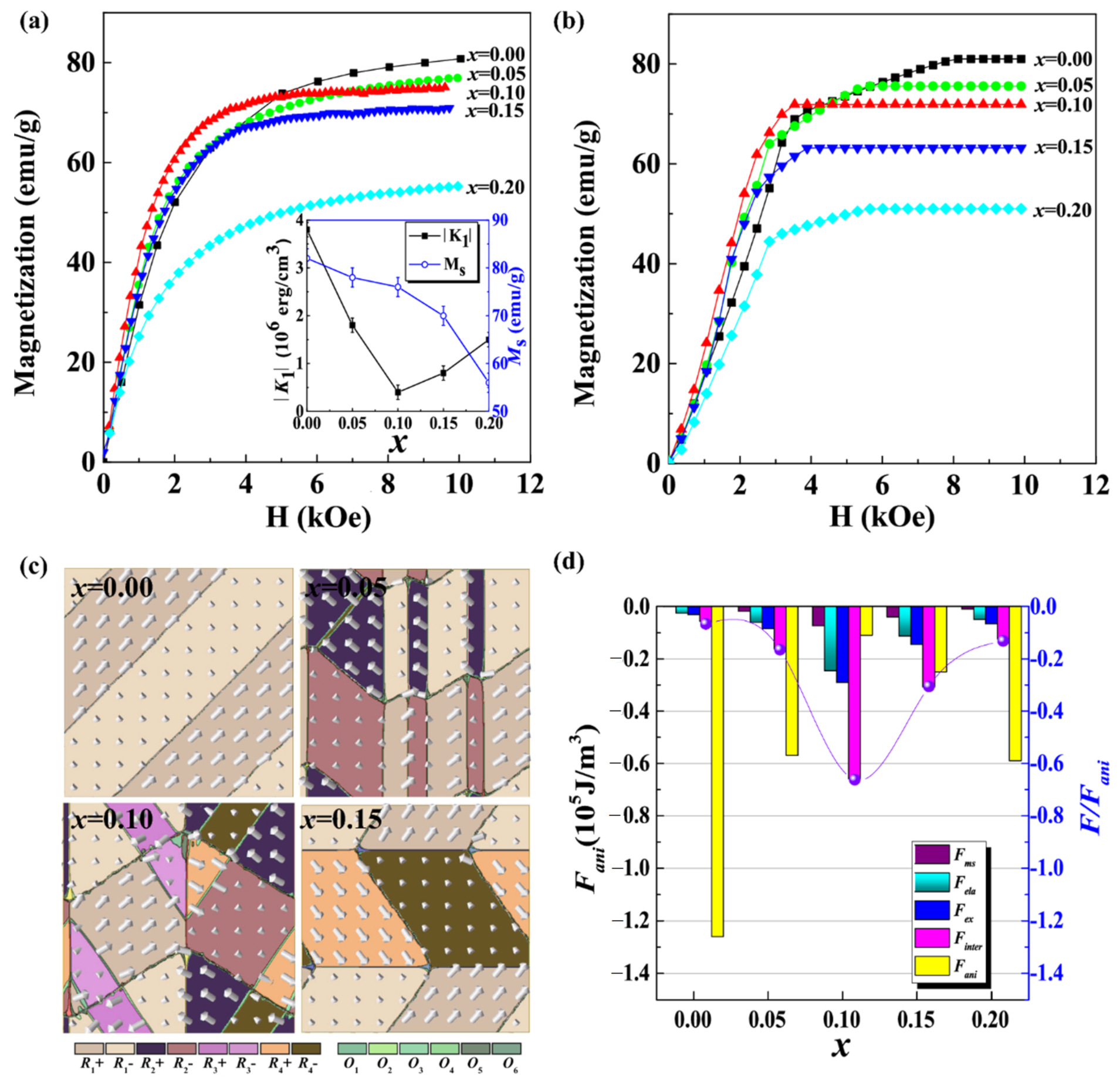
  72. Wei, S.; Liao, X.; Gao, Y.; Yang, S.; Wang, D.; Song, X. Simulation study on exchange interaction and unique magnetization near ferromagnetic morphotropic phase boundary. J. Phys. Condens. Matter 2017, 29, 445802. [Google Scholar] [CrossRef] [Green Version]
  73. Atzmony, U.; Dariel, M.P.; Dublon, G. Spin-orientation diagram of the pseudobinary Tb1−xDyxFe2 Laves compounds. Phys. Rev. B 1977, 15, 3565–3566. [Google Scholar] [CrossRef]
  74. Ma, T.Y.; Liu, X.L.; Pan, X.W.; Li, X.; Jiang, Y.Z.; Yan, M.; Li, H.Y.; Fang, M.X.; Ren, X.B. Local rhombohedral symmetry in Tb0.3Dy0.7Fe2 near the morphotropic phase boundary. Appl. Phys. Lett. 2014, 105, 192407. [Google Scholar] [CrossRef]
  75. Nie, Z.H.; Yang, S.; Wang, Y.D.; Wang, Z.L.; Liu, D.M.; Ren, Y.; Chang, T.T.; Zhang, R. In-situ studies of low-field large magnetostriction in Tb1−xDyxFe2 compounds by synchrotron-based high-energy x-ray diffraction. J. Alloys Compd. 2016, 658, 372–376. [Google Scholar] [CrossRef] [Green Version]
  76. Hu, C.C.; Yang, T.N.; Huang, H.B.; Hu, J.M.; Wang, J.J.; Shi, Y.G.; Shi, D.N.; Chen, L.Q. Phase-field simulation of domain structures and magnetostrictive response in Tb1−xDyxFe2 alloys near morphotropic phase boundary. Appl. Phys. Lett. 2016, 108, 141908. [Google Scholar] [CrossRef]
  77. Hu, C.C.; Zhang, Z.; Yang, T.N.; Li, W.; Chen, L.Q. Phase-field simulation of magnetic microstructure and domain switching in (Tb0.27Dy0.73)Fe2 single crystal. AIP Adv. 2021, 11, 015207. [Google Scholar] [CrossRef]
  78. Patrick, C.E.; Marchant, G.A.; Staunton, J.B. Spin Orientation and Magnetostriction of Tb1−xDyxFe2 from First Principles. Phys. Rev. Appl. 2020, 14, 014091. [Google Scholar] [CrossRef]
  79. Elhajjar, R.; Law, C.T.; Pegoretti, A. Magnetostrictive polymer composites: Recent advances in materials, structures and properties. Prog. Mater. Sci. 2018, 97, 204–229. [Google Scholar] [CrossRef]
  80. Lo, C.Y.; Or, S.W.; Chan, H.L.W. Large Magnetostriction in Epoxy-Bonded Terfenol-D Continuous-Fiber Composite with [112] Crystallographic Orientation. IEEE Trans. Magn. 2006, 42, 3111–3113. [Google Scholar] [CrossRef] [Green Version]
  81. Ho, K.K.; Henry, C.P.; Altin, G.; Carman, G.P. Crystallographically Aligned Terfenol-D/Polymer Composites for a Hybrid Sonar Device. Integr. Ferroelectr. 2006, 83, 121–138. [Google Scholar] [CrossRef]
  82. Dong, X.F.; Qi, M.; Guan, X.C.; Li, J.H.; Ou, J.P. Magnetostrictive properties of titanate coupling agent treated Terfenol-D composites. J. Magn. Magn. Mater. 2012, 324, 1205–1208. [Google Scholar] [CrossRef]
  83. Meng, H.; Zhang, T.L.; Jiang, C.B. Cut-off frequency of magnetostrictive materials based on permeability spectra. J. Magn. Magn. Mater. 2012, 324, 1933–1937. [Google Scholar] [CrossRef]
  84. Meng, H.; Zhang, T.L.; Jiang, C.B.; Xu, H.B. Grain-<111>-oriented anisotropy in the bonded giant magnetostrictive material. Appl. Phys. Lett. 2010, 96, 102501. [Google Scholar] [CrossRef]
  85. Kaleta, J.; Lewandowski, D.; Mech, R. Magnetostriction of field-structural composite with Terfenol-D particles. Arch. Civ. Mech. Eng. 2015, 15, 897–902. [Google Scholar] [CrossRef]
  86. Lin, L.L.; Liu, J.J.; Shen, W.C.; Ding, Q.L.; Wang, M.K.; Du, J.; Si, P.Z. Magnetomechanical behavior of Tb0.2Dy0.8−xPrx(Fe0.8Co0.2)1.93/epoxy pseudo-1-3 particulate composites. Appl. Phys. A 2018, 124, 706. [Google Scholar] [CrossRef]
  87. Li, B.C.; Zhang, T.L.; Wu, Y.Y.; Jiang, C.B. High-performance magnetostrictive composites with large particles volume fraction. J. Alloys Compd. 2019, 805, 1266–1270. [Google Scholar] [CrossRef]
  88. Lv, X.; Liu, J.; Ding, Q.; Wang, M.; Pan, Z. Textured Orientation and Dynamic Magnetoelastic Properties of Epoxy-Based TbxDy0.7−xPr0.3(Fe0.9B0.1)1.93 Particulate Composites. J. Supercond. Novel Magn. 2020, 33, 3857–3864. [Google Scholar] [CrossRef]
  89. Du, T.; Zhang, T.L.; Meng, H.; Zhou, X.M.; Jiang, C.B. A study on laminated structures in Terfenol-D/Epoxy particulate composite with enhanced magnetostriction. J. Appl. Phys. 2014, 115, 243909. [Google Scholar] [CrossRef]
  90. Zhou, Z.G.; Li, J.H.; Bao, X.Q.; Liu, M.; Gao, X.X. Improvement of mechanical properties of magnetostrictive Tb-Dy-Fe alloys via preparing sintered material with low-melting Dy-Cu alloy binder. J. Alloys Compd. 2022, 895, 162572. [Google Scholar] [CrossRef]
  91. Arout Chelvane, J.; Sherly, A.; Palit, M.; Talapatra, A.; Mohanty, J. Magnetic anisotropy and magnetostrictive properties of sputtered Tb-Dy-Fe-Co thin films. J. Mater. Sci. Mater. Electron. 2019, 30, 8989–8995. [Google Scholar] [CrossRef]
  92. Panduranga, M.K.; Lee, T.; Chavez, A.; Prikhodko, S.V.; Carman, G.P. Polycrystalline Terfenol-D thin films grown at CMOS compatible temperature. AIP Adv. 2018, 8, 056404. [Google Scholar] [CrossRef] [Green Version]
  93. Lee, C.H.; Chang, W.C.; Anbalagan, A.K. Anomalous X-ray scattering study on oxidized TbxDy1−xFe2-y thin films: Influence of thermal annealing on the oxide composition. Radiat. Phys. Chemistry 2020, 175, 108915. [Google Scholar] [CrossRef]
  94. Panduranga, M.K.; Xiao, Z.Y.; Schneider, J.D.; Lee, T.; Klewe, C.; Chopdekar, R.; Shafer, P.; N’Diaye, A.T.; Arenholz, E.; Candler, R.N.; et al. Single magnetic domain Terfenol-D microstructures with passivating oxide layer. J. Magn. Magn. Mater. 2021, 528, 167798. [Google Scholar] [CrossRef]
  95. Shim, H.; Sakamoto, K.; Inomata, N.; Toda, M.; Toan, N.V.; Ono, T. Magnetostrictive Performance of Electrodeposited TbxDy1−xFey Thin Film with Microcantilever Structures. Micromachines 2020, 11, 523. [Google Scholar] [CrossRef]
  96. Yu, C.Q.; Niu, R.; Peng, Z.D.; Li, H.; Luo, Y.M.; Zhou, T.J.; Dong, C.H. A Current Sensor Based on Capillary Microresonator Filled with Terfenol-D Nanoparticles. IEEE Photonics Technol. Lett. 2021, 33, 239–242. [Google Scholar] [CrossRef]
  97. Sun, Y.; Wang, W.; Jia, Y.N.; Fan, S.Y.; Liang, Y. Sensitivity Improvement of TbDyFe Thin-Film Coated Saw-Based Current Sensor. In Proceedings of the 2019 14th Symposium on Piezoelectrcity, Acoustic Waves and Device Applications (Spawda19), Shijiazhuang, China, 11–14 January 2019; pp. 519–522. [Google Scholar]
  98. Shen, X.L.; Sun, H.Y.; Sang, L.W.; Imura, M.; Koide, Y.; Koizumi, S.; Liao, M.Y. Integrated TbDyFe Film on a Single-Crystal Diamond Microelectromechanical Resonator for Magnetic Sensing. Phys. Status Solidi-Rapid Res. Lett. 2021, 15, 2100352. [Google Scholar] [CrossRef]
  99. Sakon, T.; Matsumoto, T.; Komori, T. Rotation angle sensing system using magnetostrictive alloy Terfenol-D and permanent magnet. Sens. Actuators A 2021, 321, 112588. [Google Scholar] [CrossRef]
  100. Zhu, L.L.; Li, K.S.; Luo, Y.; Yu, D.B.; Wang, Z.L.; Wu, G.Y.; Xie, J.J.; Tang, Z.F. Magnetostrictive properties and detection efficiency of TbDyFe/FeCo composite materials for nondestructive testing. J. Rare Earths 2019, 37, 166–170. [Google Scholar] [CrossRef]
  101. Rajagopal, M.C.; Sinha, S. Design and analysis of magnetostrictive sensors for wireless temperature sensing. Rev. Sci. Instrum. 2021, 92, 014901. [Google Scholar] [CrossRef]
  102. Kaplan, N.; Jasenek, J.; Cervenova, J.; Usakova, M. Magnetic Optical FBG Sensors Using Optical Frequency-Domain Reflectometry. IEEE Trans. Magn. 2019, 55, 1–4. [Google Scholar] [CrossRef]
  103. Kaplan, N.; Jasenek, J.; Cervenova, J. The Influence of Magnetic Field Applied on Fiber Bragg Gratings. Aip. Conf. Proc. 2018, 1996, 020024. [Google Scholar] [CrossRef]
  104. Karanja, J.M.; Dai, Y.T.; Zhou, X.; Liu, B.; Yang, M.H.; Dai, J.X. Femtosecond Laser Ablated FBG Multitrenches for Magnetic Field Sensor Application. IEEE Photonics Technol. Lett. 2015, 27, 1717–1720. [Google Scholar] [CrossRef]
  105. Shao, Z.H.; Qiao, X.G.; Rong, Q.Z.; Sun, A. Fiber-optic magnetic field sensor using a phase-shifted fiber Bragg grating assisted by a TbDyFe bar. Sens. Actuators A 2017, 261, 49–55. [Google Scholar] [CrossRef]
  106. Feng, X.X.; Jiang, Y.; Zhang, H. A mechanical amplifier based high-finesse fiber-optic Fabry-Perot interferometric sensor for the measurement of static magnetic field. Meas. Sci. Technol. 2021, 32, 125106. [Google Scholar] [CrossRef]
Figure 1. Three forms of solid–liquid interface morphologies under the condition of V = 15 mm/h with different half zone-melting lengths: (a) P = 60; L1/2 = 7 mm (convex); (b) P = 70; L1/2 = 10 mm (flat); (c) P = 80; L1/2 = 15 mm (concave) [19] (here, P is heating power) (Reprinted with permission from Ref. [19]. Copyright 2015 Elsevier).
Metals 12 00341 g001
Figure 2. Comparison of atomic attachment kinetics at (a) (111) and (b) (311) interfaces; (c) magnetostriction (λ) of directionally solidified samples measured at an applied field of 5 kOe and (d) the plot of slope (dλ/dH) of the initial λ-H plot, plotted as a function of growth rate [21] (Adapted with permission from Ref. [21]. 2016 Springer Nature).
Metals 12 00341 g002
Figure 3. Octahedral configuration: (a) a faceted equiaxed grain m bounded by eight {111} planes; (b) occurrence of double parallel twin boundaries on the (11 1 ¯ ) plane of the crystal; (c) twinned lamellas grow on the (11 1 ¯ ) plane; (d) twinned lamellas grow on four different {111} planes [24]. Reprinted with permission from ref. [24]. Copyright 2018 Elsevier.
Metals 12 00341 g003
Figure 4. (a) XRD patterns in the plane perpendicular to the magnetic field direction and (b) magnetostriction for Tb0.27Dy0.73Fe1.95 alloys solidified in various high magnetic fields [27]. Reprinted with permission from Ref. [27]. Copyright 2016 Elsevier.
Metals 12 00341 g004
Figure 5. (a) XRD patterns of Tb0.27Dy0.73Fe1.95 alloys on the transverse section; (b,c) SEM images of the alloy structures grown with (b) 0T and (c) 6 T magnetic field [29]. Reprinted with permission from ref. [29]. Copyright 2020 AIP Publishing.
Metals 12 00341 g005
Figure 6. (a) The maximum magnetostriction of alloys solidified in various high magnetic fields at 4000 Oe and (b) saturation magnetization through the depths of alloys solidified in various high magnetic fields [32]. Reprinted with permission from Ref. [32]. Copyright 2016 World Scientific Publishing Company.
Metals 12 00341 g006
Figure 7. (a) Typical step-scanned 440C XRD profiles of the (Tb0.2Pr0.8)xDy1−xFe1.93 Laves phase, and room temperature magnetostriction λas a function of (b) the applied field and (c) the composition [41]. Reprinted with permission from Ref. [41]. Copyright 2019 Elsevier.
Metals 12 00341 g007
Figure 8. Designed ternary composition phase diagram for the Tb-Dy-Pr system: the location between two bias diagonals of the rare-earth composition is indicated along the expected minimum anisotropy line [42]. Reprinted with permission from Ref. [42]. Copyright 2020 Springer Nature.
Metals 12 00341 g008
Figure 9. For Tb0.27Dy0.73−xNdxFe2: (a) spin configuration phase diagram accompanied by the cubic, rhombohedral and tetragonal crystal symmetries and (b) room temperature magnetostriction (λS) (x = 0.0, 0.1.0.2, 0.3, 0.4) [52]. Reprinted with permission from ref. [52]. Copyright 2020 Elsevier.
Metals 12 00341 g009
Figure 10. (a) XRD patterns and magnetic-field dependence of (b) magnetostriction and (c) normalized magnetostriction for Tb0.1Ho0.9−xPrx(Fe0.8Co0.2)1.93 alloys [55]. Reprinted with permission from Ref. [55]. Copyright 2016 Elsevier.
Metals 12 00341 g010
Figure 11. BSEM images and X-ray diffraction patterns of the alloys (a) Tb0.3Dy0.7Fe2; (b) (Tb0.3Dy0.7)0.3Fe0.6Co0.1; (c) (Tb0.3Dy0.7)0.3Fe0.6Cu0.1; (d) (Tb0.3Dy0.7)0.3Fe0.6Nb0.1; (e) (Tb0.3Dy0.7)0.3Fe0.6Ti0.1; (f) (Tb0.3Dy0.7)0.3Fe0.6V0.1 [59]. Reprinted with permission from ref. [59]. Copyright 2018 Elsevier.
Metals 12 00341 g011
Figure 12. SEM images of crack propagation and soft phase deformation during the compressive fracture process in alloys. (a,b) (Tb0.3Dy0.7)0.37Fe0.63; (c,d) (Tb0.3Dy0.7)0.37Fe0.62Cu0.01; (e) (Tb0.3Dy0.7)0.37Fe0.53Cu0.1 [68]. Reprinted with permission from ref. [68]. Copyright 2019 Elsevier.
Metals 12 00341 g012
Figure 13. (a) SEM images and (b) bending strength and magnetostrictive properties of the Tb0.3Dy0.7Fe1.95 alloy diffused by DyCu2 alloy at 980 °C for 3 h, followed by quenching to room temperature; the inset in (a) is SAED pattern of DyCu along the [111] zone axis [69]. Reprinted with permission from ref. [69]. Copyright 2020 Elsevier.
Metals 12 00341 g013
Figure 14. Stress–strain curves of Tb0.27Dy0.73Fe1.95 alloys that were solidified directionally at various growth velocities without and with a 6 T magnetic field: (a) 25 μm/s; (b) 50 μm/s; (c) 100 μm/s; (d) 200 μm/s [31]. Reprinted with permission from ref. [31]. Copyright 2020 Elsevier.
Metals 12 00341 g014
Figure 15. Phase diagram of Tb1−xDyxFe2. The background shading shows the magnetic easy axis direction calculated using anisotropy parameters from crystal field theory (see text) [71]. Overlayed is the morphotropic phase boundary determined from our synchrotron XRD (dotted lines) and magnetometry (solid line) measurements, as well as the easy axes reported previously on the basis of Mӧssbauer spectroscopy (open symbols) [73]. A cross in a circle indicates the optimal temperature (40 °C) for magnetomechanical device applications, as determined for Tb1−xDyxFe2 x = 0.73 [2].
Metals 12 00341 g015
Figure 16. Domains of Tb0.3Dy0.7Fe2 at 293 K revealed by HRTEM [74]. (a) HRTEM image taken along the [1 1 ¯ 4]C incident direction. Upper inset is the SAED pattern, and bottom inset is the schematic unit cell with spontaneous magnetization direction. (b) FFT of the white rectangle in (a) shows splitting reflection spots due to rhombohedral lattice distortion. (c) IFFT image by using the {311}C/{111}R reflections in the bottom inset of (a), corresponding to the same area in (a). The inset is the corresponding FFT spectrum. (d) IFFT image by using the {311}C/{111}R reflections from the FFT in (b). Adapted with permission from ref. [74]. Copyright 2014 Elsevier.
Metals 12 00341 g016
Figure 17. (a) Temperature-dependent pair distribution function (PDF) for Tb0.4Dy0.6Fe2; (b) the rhombohedral cell (pink solid) and cubic cell (teal dashed) for Tb1−xDyxFe2; (c) temperature-dependent lattice constants and bond lengths for Tb0.4Dy0.6Fe2 [18]. Reprinted with permission from ref. [18]. Copyright 2020 AIP Publishing.
Metals 12 00341 g017
Figure 18. (a) Room temperature Fe K-edge XANES spectra for Fe foil and Tb1−xDyxFe2 samples. (b) Room temperature Fe K-edge EXAFS spectra for Tb1−xDyxFe2 [18]. Reprinted with permission from ref. [18]. Copyright 2020 AIP Publishing.
Metals 12 00341 g018
Figure 19. (a) Integrated intensity fraction of (344)R diffraction peak and (b) schematic of the microstructural evolutions in TbFe2 and Tb0.4Dy0.6Fe2 compounds under an applied magnetic field [75]. Reprinted with permission from ref. [75]. Copyright 2016 Elsevier.
Metals 12 00341 g019
Figure 20. (a) Magnetization curves for (Tb0.27Dy0.73)1−x(Tb0.1Pr0.9)x(Fe0.9Co0.1)2 compounds (0 ≤ x ≤ 0.2). The inset shows the absolute values of the first-order anisotropy constant |K1| and saturation magnetization MS at room temperature. (b) The calculated average magnetization Mxy from phase-field simulation for the corresponding experimental compositions. (c) Snapshots of domain structures for the samples with 0.00 ≤ x ≤ 0.15. (d) Energy analysis for the samples with 0.00 ≤ x ≤ 0.20 [42]. Reprinted with permission from ref. [42]. Copyright 2020 Springer Nature.
Metals 12 00341 g020
Figure 21. The easy direction of magnetization of Tb1−xDyxFe2, calculated by minimizing E(û, ε, x, T) (red- and blue-shaded regions) [78]. Reprinted with permission from ref. [78]. Copyright 2020 American Physical Society.
Metals 12 00341 g021
Figure 22. Magnetostriction curves of static magnetically oriented GMPCs and GMPCs subjected to a molding procedure under (a) 0 MPa and (b) 10 MPa uniaxial pressure; (c) elastic modulus curves and (d) energy densities of GMPC samples [87]. Reprinted with permission from ref. [87]. Copyright 2019 Elsevier.
Metals 12 00341 g022
Figure 23. (a) The forming device; (b) schematic diagram of the forming device; (c) two-step molding procedure diagram [87]. Reprinted with permission from ref. [87]. Copyright 2019 Elsevier.
Metals 12 00341 g023
Figure 24. Schematic diagram of preparation procedure of the oriented sintered Tb0.33Dy0.67Fe1.95 compacts [90]. Reprinted with permission from ref. [90]. Copyright 2022 Elsevier.
Metals 12 00341 g024
Figure 25. (a) XRD of the diffraction patterns of oriented and nonoriented sintered Tb0.33Dy0.67Fe1.95 compacts at 1000 °C and λ//, λ magnetostriction curves, dependence of strain coefficient (d33) of the oriented sintered Tb0.33Dy0.67Fe1.95 compacts on magnetic field (H) under uniaxial pressure (b) 0 MPa, and (c) 10 MPa [90]. Reprinted with permission from ref. [90]. Copyright 2022 Elsevier.
Metals 12 00341 g025
Figure 26. M vs. H plots of patterned Terfenol-D microdisks measured over the course of 100 days. Bottom-right inset shows the normalized M vs. H plots of continuous, 20 µm diameter disks and 3 µm diameter disks. Top-right inset shows the schematic of Terfenol-D disk with sidewall oxidation. Top-left inset shows magnetic force microscope image of an individual 3 μm disk upon initializing with an in-plane saturation magnetic field of 0.5 T and PEEM image of 20 μm disk indicating the single domain state when measured with Dy-M5 edge [94]. Reprinted with permission from ref. [94]. Copyright 2021 Elsevier.
Metals 12 00341 g026
Figure 27. Magnetostriction coefficients of the Tb0.36Dy0.64Fe1.9 film obtained from three cantilevers with lengths 700, 1000 and 1100 µm [95]. Reprinted from ref. [94].
Metals 12 00341 g027
Table 1. Properties of various GMPCs reported in the literature.
CompositeOrientationPreparationMagnetostrictive Particle MorphologyMagnetostrictive Particle SizeParticle ContentMagnetostriction or CommentsReferences
Tb0.3Dy0.7Fe1.9/epoxy<111>8000 Oe magnetic field curingParticles;
pseudo-1–3 chain structure
>300 μm40 vol%1358 ppm (at 17 MPa)[84]
Tb0.3Dy0.7Fe1.92/epoxy-8000 Oe magnetic field curing-200–300 μm40 vol%Cut-off frequency is 6800 kHz; loss factor is only 4.3% of that for the monolithic Tb-Dy-Fe alloy (at 10 kHz and 10 mT)[83]
Tb0.4Dy0.5Nd0.1(Fe0.8Co0.2)1.93/epoxy<111>10 kOe magnetic field curingParticles;
pseudo-1–3 chain structure
≤150 μm20 vol%390 ppm (λa is 650 ppm at 6 kOe)[45]
Terfenol-D/epoxy<112>1885 Oe magnetic field curingPowder, particle;
pseudo-1–3 chain structure
5–300 μm70 vol%720 ppm (at 9 MPa)[85]
(Tb0.15Ho0.85Fe1.9)0.31 + (Tb0.3Dy0.7Fe1.9)0.69/epoxy Pressure curing moldingParticles;
pseudo-1–3 chain structure
75–180 μm94 wt%605 ppm[57]
Tb0.25Dy0.45Ho0.30Fe1.9/epoxy<110>120 ℃ bonding molding<110> staple fiber0.8 mm × 0.8 mm ×12 mm90 vol%220 kA/M saturated magnetic field; 5 kA/M coercivity; the total loss at 20 kHz is 115 W/m3[56]
Tb0.2Dy0.55Pr0.25(Fe0.8Co0.2)1.93/epoxy<110>8042 Oe magnetic field curingParticles;
pseudo-1–3 chain structure
75–150 µm30 vol%110 ppm (λ||, at 80 kA/m);
580 ppm (λa, at 950 kA/m)
[86]
Tb0.5Dy0.5Fe1.95/epoxy<111>Two-step method with 10 kOe dynamic magnetic orientationLamellar structure100–200 µm57 vol%1500 ppm[87]
TbxDy0.7−xPr0.3(Fe0.9B0.1)1.93/epoxy<111>8042 Oe magnetic field curingParticles;
pseudo-1–3 chain structure
60–150 μm30 vol%d33~2.2 nm/A (Hbias~80 kA/m)[88]
Publisher’s Note: MDPI stays neutral with regard to jurisdictional claims in published maps and institutional affiliations.

