Article

Effects of Long-Term Service on Microstructure and Impact Toughness of the Weld Metal and Heat-Affected Zone in CrMoV Steel Joints

1
Department of Mechanical Engineering, Tsinghua University, Beijing 100084, China
2
Key Laboratory for Advanced Materials Processing Technology, Ministry of Education, Beijing 100084, China
3
State Key Laboratory of Tribology, Tsinghua University, Beijing 100084, China
4
Collaborative Innovation Center of Advanced Nuclear Energy Technology, Tsinghua University, Beijing 100084, China
5
Fundamental Industry Training Center, Tsinghua University, Beijing 100084, China
*
Author to whom correspondence should be addressed.
Metals 2022, 12(2), 278; https://doi.org/10.3390/met12020278
Submission received: 10 January 2022 / Revised: 30 January 2022 / Accepted: 31 January 2022 / Published: 3 February 2022

Abstract

:
The microstructure and impact toughness of weld metals (WMs) and heat-affected zones (HAZs) of a low-alloy CrMoV steel gas turbine rotor which had served for 14 years were investigated. The ex-service joints in the turbine part (serving at 500–540 °C) and the compressor part (serving below 300 °C) of the rotor were selected for comparative research. The microstructure of the WMs and HAZs between the turbine part and the compressor part was similar, indicating that there was no significant deterioration in microstructure of the turbine part during service. However, compared with the compressor part WM, the impact energy of the turbine part WM decreased significantly, and FATT50 increased greatly. The degraded toughness of turbine part WM was related to more serious intergranular cracking caused by higher segregation level of phosphorus (P) at prior austenite grain (PAG) boundaries. Welding and post-weld heat treatment led to obvious segregation of P at PAG boundaries in WMs, and the segregation of P in turbine part WM was further aggravated during serving at 500–540 °C. Additionally, the inhomogeneous microstructure of the WMs also aggravated the segregation of P. The toughness of the HAZs in both turbine part and compressor part was high, which was because of fine grains. Furthermore, due to there being more grain boundaries and low P content, the segregation of P in HAZs was slight and its adverse effect on the toughness could be ignored.

1. Introduction

Due to the excellent elevated temperature strength, the good oxidation resistance, and the high hydrogen embrittlement resistance, low-alloy CrMoV steels are widely used for high-temperature applications in the power, chemical, and oil industries [1,2,3]. In the power industry, these steels are extensively used to manufacture critical components operated under the circumstances of high temperature, high pressure, and dynamic loads [1,2,3]. At present, thousands of thermal power generating units in China have been in service for more than ten to twenty years. The microstructure and mechanical properties of these steels might deteriorate during service, leading to threats to the service safety of critical components [1,2,3,4,5]. Thus, investigating the effects of service on the microstructure and the mechanical properties of low-alloy CrMoV steels is meaningful for ensuring service safety and assessing the remaining service life of critical components in generating units.
As the most critical components for energy conversion and torque transmission in the power units, turbine rotors experience huge centrifugal force, torsional force, and bending stress during operation [6,7]. Meanwhile, turbine rotors also generally experience tens to hundreds of start-ups and shut-downs per year [8], undergoing a temperature change of more than 500 °C in a short time, as well as the tremendous accompanying thermal stress and shock loads. Therefore, fracture failure during the start-up and shut-down process has become one of the main failure modes of rotors [7,8,9,10,11]. Therefore, high impact toughness is essential to ensure the safe service of rotors. However, the impact toughness of low-alloy CrMoV steels may deteriorate during serving under high-temperature conditions for long periods of time [1,2,4,5,12,13].
Previous studies [1,2,3,4,5,12,13] have shown that temperature is the most important factor affecting the degradation of low-alloy CrMoV steels in service. Generally, the microstructure and properties of CrMoV steels do not change when in service at temperatures below 300 °C [1,2]. With the increase of service temperature (generally to above 400 °C), CrMoV steels undergo reversible embrittlement caused by the segregation of P, Sn, As, and Sb at prior austenite grain (PAG) boundaries. The segregation of P, Sn, As, and Sb could result in a decrease in the impact toughness and an increase in the fracture appearance transition temperature (FATT50) [1,3,13]. As the service temperature increases further (generally to above 500 °C), softening and irreversible embrittlement might occur due to the coarsening of carbides and the precipitation of more stable carbides during service [1,2,4,5,12].
With the advantages of flexible material selection and low cost, welding is widely applied in the fabricating turbine rotors and other large critical components [7,9,10,11,14]. Nevertheless, owing to the complex welding heat process, the microstructure and the mechanical properties of weld metals (WMs) and heat-affected zones (HAZs) are inhomogeneous. Thus, the WMs and HAZs may become weak positions of components [9,14]. Furthermore, the inhomogeneous microstructure and properties also lead to the effects of service being more complicated. Despite this, there is only limited literature exploring the effects of long-term high-temperature service on the microstructure and the impact toughness of the WMs and HAZs in CrMoV steel turbine rotors.
In this paper, we investigate the impact toughness and FATT50 of the WMs and HAZs in the turbine part and the compressor part of an ex-service gas turbine welded rotor. The microstructure, fracture appearance, fracture path, and impurity element segregation at PAG boundaries of the specimens were systematically investigated. The effects of long-term high-temperature service on the microstructure, the toughness, and the cracking behaviors of the WMs and HAZs are discussed and clarified.

2. Materials and Methods
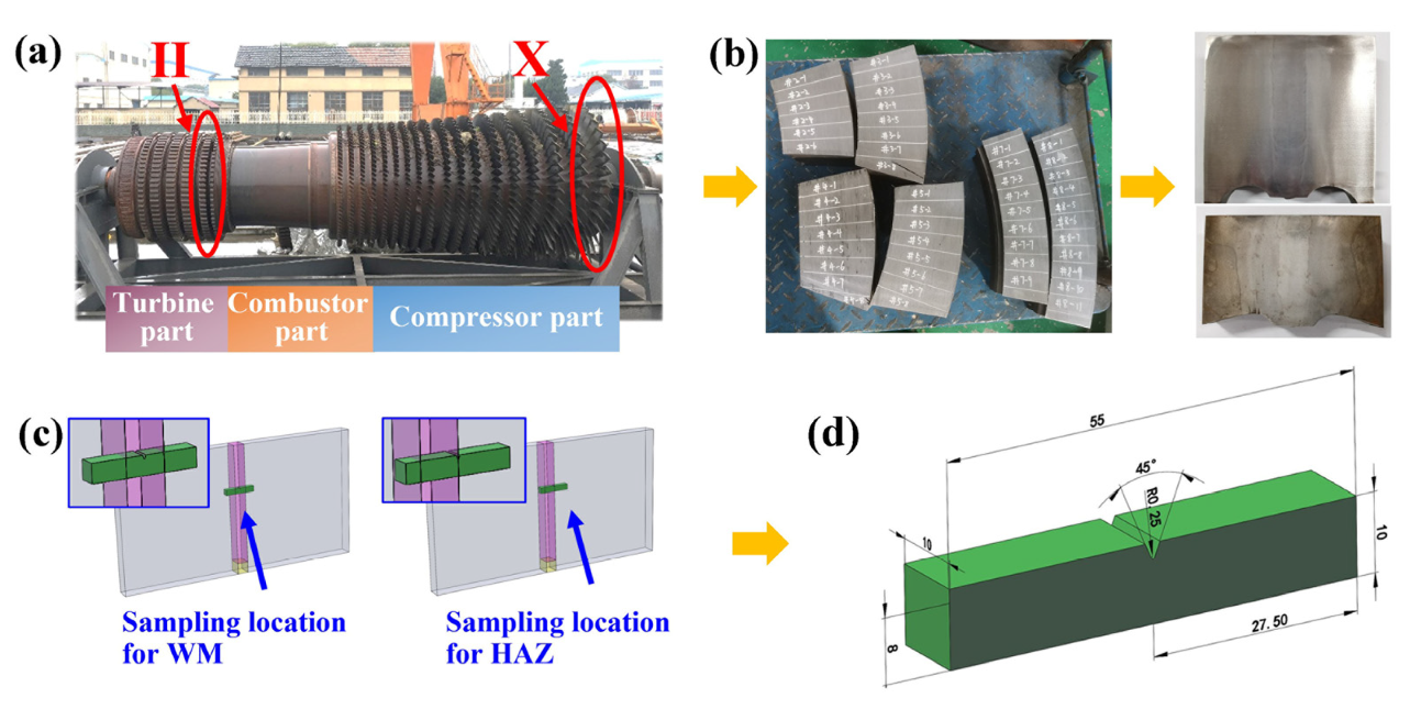
2.1. Materials

As shown in Figure 1a, the material studied in this research was a gas turbine welded rotor which had been in service for 14 years. Region II (II in Figure 1a) was located at the inlet of high-temperature gas with the highest service temperature (about 500–540 °C), which was called the turbine part. Region X (X in Figure 1a) was located at the inlet of compressed air with the lowest service temperature (below 300 °C), which was called the compressor part. The chemical composition, welding process, and post-weld heat treatment process between the turbine part and the compressor part were the same. Table 1 shows the chemical composition of base metals (BMs) and weld metals (WMs). The composition of the heat-affected zones (HAZs) is the same as that of the BMs. Generally, the microstructure and properties of CrMoV steels do not change during service below 300 °C [1,2]. Therefore, the compressor part was regarded as being in approximately the same state as before service. In this research, welded joints in the turbine part and the compressor part were selected to investigate the effects of long-term service on the microstructure and mechanical properties of the WM and HAZ.

2.2. Microstructure

The microstructure of the WMs and HAZs was observed and analyzed by optical microscope (OM), scanning electron microscope (SEM), and electron back-scattered diffraction (EBSD). Additionally, the chemical composition and the element mapping of carbides were analyzed by high-resolution energy-dispersive X-ray spectrometry (EDX). The specimens for OM, SEM, and EDX analysis were etched by the solution made up of nitric acid (4 mL) and ethanol (96 mL) for 20 s. The specimens for EBSD observations were electro-polished using a solution of phosphoric acid (60 mL), sulfuric acid (20 mL), glycerin (15 mL), and Cr2O3 (5 g) at a voltage of 6 V and a current of 1.2 A for 30 s. The step size for EBSD operation was 0.3 μm.

2.3. Toughness Tests

Standard Charpy V-notch impact tests were conducted at 25 °C to assess the impact toughness of the WMs and HAZs in the turbine part and the compressor part, according to the standard ISO 148-1: 2006 [15]. The sampling location and the specimen dimensions are shown in Figure 1c,d, respectively. The V-notch of the WM specimens was located at the weld center, where the weld beads overlapped (see in Figure 2b and Figure 3b). The V-notch of the HAZ specimens was located at the fine-grained HAZ (FGHAZ) (see Figure 4a and Figure 5a), where the area proportion was the largest in HAZ. In addition, FATT50 is an important indicator for evaluating the degree of embrittlement [16,17,18], so the FATT50 of the turbine part WM and the compressor part WM was also tested. Subsequently, the fracture morphology of the broken specimens was observed by SEM, and the crack growth path of the broken impact specimens was observed by OM.

2.4. Auger Electron Spectroscopy Analysis

To detect the segregation of impurity elements at prior austenite grain (PAG) boundaries in the WMs and HAZs, Auger electron spectroscopy (AES) analyses were conducted using an Axis Supra X-ray photoelectron spectrometer system. The geometry of AES specimens was a cylinder of 3 mm in diameter and 19.5 mm in length, with a notch of 2 mm in the center. The specimens were cooled by liquid nitrogen for more than 30 min in the Auger high vacuum chamber. Then, they were quickly impacted to get an intergranular fracture surface by the impact fracture device in the Auger high vacuum chamber. Subsequently, AES analysis was carried out as quickly as possible to avoid contamination in the vacuum chamber. Element content at PAG boundaries was calculated according to the method mentioned in relevant literature [16,17,18,19]. About 10–15 grain boundaries were analyzed for each specimen and the average value was taken as the segregated element concentration.

3. Results and Discussion
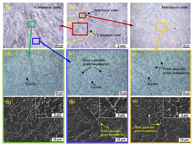
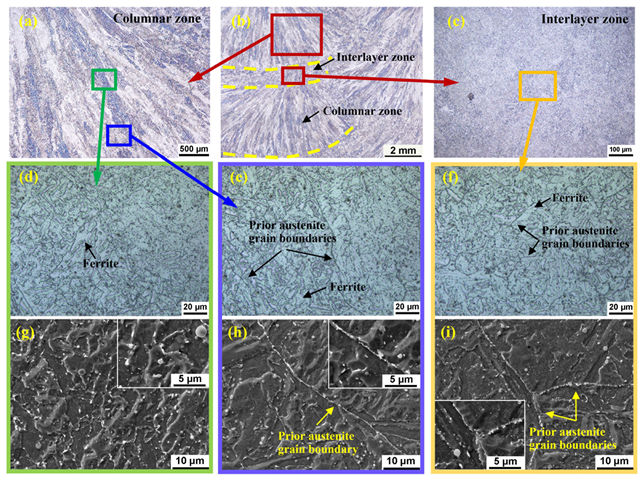
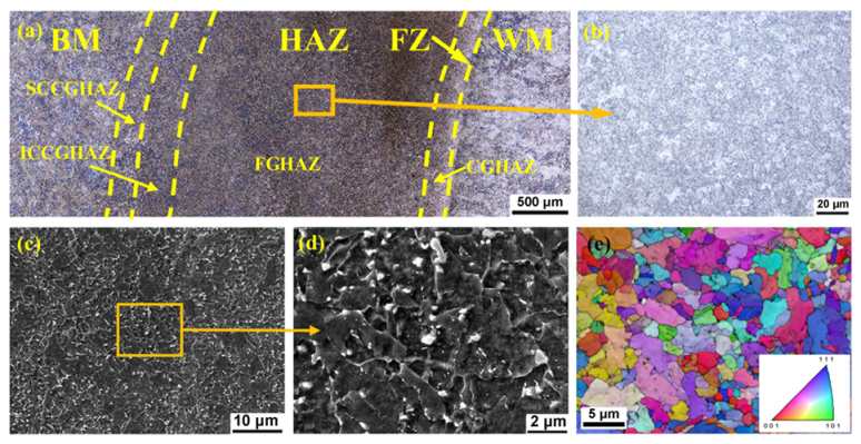
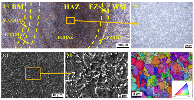
3.1. Microstructure

Figure 2 and Figure 3 show the microstructure of the WMs in the turbine part and the compressor part, respectively. The WMs were multi-layer and double-pass structures, consisting of the columnar zone and the interlayer zone. As shown in Figure 2d,e,g,h, due to complex thermal effects of the next weld on the previous weld, the microstructure in the columnar zone was inhomogeneous. There were no obvious prior austenite grain (PAG) boundaries in the upper part of columnar zone (see in Figure 2d,g), while PAG boundaries were obvious in the lower part of columnar zone (see in Figure 2e,h). The PAGs in the columnar zone were hundreds of microns in length and 50 μm to 100 μm in width. As shown in Figure 2c,f,i, the microstructure of the interlayer zone of the WM was equiaxed grains, and the diameter of PAGs was about 30 μm to 70 μm. The equiaxed grains were formed by the thermal effects from other layers and passes of the melted metal on the columnar grains formed previously. As shown in Figure 2d–f, the microstructure of turbine part WM was mainly bainite and a few massive ferrites. Figure 3 shows the microstructure in compressor part WM, microstructure types and PAGs sizes in the compressor part WM were similar to those in the turbine part WM.
Figure 4 and Figure 5 show the microstructure of the HAZs in the turbine part and the compressor part, respectively. The HAZs, with a width of about 3 mm, consist of coarse-grained HAZ (CGHAZ), fine-grained HAZ (FGHAZ), intercritically reheated coarse-grained HAZ (ICCGHAZ), and subcritically reheated coarse-grained HAZ (SCCGHAZ) [20]. As shown in Figure 4 and Figure 5, the microstructure in the HAZs was mainly fine grains and the area proportion of the FGHAZ was the largest. This was due to the complicated thermal cycles of multi-layer and multi-pass welding. Figure 4b–e show the microstructure details of the FGHAZ in turbine part HAZ. As shown in Figure 4b–d, the microstructure was fine grains and was mainly bainite. Because the sizes of fine grains were difficult to determine by OM and SEM, EBSD was employed to analyze grain sizes. As shown in Figure 4e, the sizes of grain in the FGHAZ were about 3–7 μm. Figure 5b–e show the microstructure details of the FGHAZ in the compressor part HAZ. The microstructure types and grain sizes in the compressor part HAZ were similar to those in the turbine part HAZ.
In addition, Figure 2, Figure 3, Figure 4 and Figure 5 show that both grain interiors and boundaries of the WMs and HAZs contain many carbides, and carbides at grain boundaries had a higher density and a larger size. To further compare the carbides between the turbine part and the compressor part, high-resolution EDX was used. Figure 6 and Figure 7 show the element distribution maps of the WMs and HAZs, respectively.
Figure 6a,d show carbides in the upper part of columnar zones in the turbine part WM and the compressor part WM, respectively. Carbides in these zones were mainly distributed in matrix, since there were little PAG boundaries. The sizes and the composition of carbides were similar, which were both hundreds of microns and rich in Cr and Mo. Figure 6b,e show that the carbides in the lower part of columnar zones were also similar. The carbides were mainly distributed along the PAG boundaries and rich in Cr and Mo. Figure 6c,f show that characteristics of carbides in the interlayer zone were similar to carbides in the lower part of columnar zone. Figure 7 show that carbides in the FGHAZs of turbine part and compressor part were also similar, which were both mainly distributed in matrix and rich in Cr and Mo. Therefore, compared with the compressor part WM and HAZ, no noticeable changes occurred in the microstructure of the turbine part WM and HAZ. Therefore, there was no obvious microstructure degradation in the turbine part WM and HAZ during serving at 500–540 °C for 14 years.

3.2. Impact Energy and FATT50

Table 2 shows the results of impact energy and FATT50 of the WMs and HAZs. The impact energy of the turbine part WM (15 J) decreased by 61% compared to that of the compressor part WM (38 J). While the impact energy of the turbine part HAZ (156 J) was just decreased by 12% compared to that of the compressor part HAZ (177 J). The impact energy of the WMs was much lower than that of the HAZs, indicating that the WMs were the weak positions of this rotor. Therefore, further attention was paid to the toughness of the WMs and their FATT50 was tested. FATT50 of the turbine part WM (138 °C) was higher than that of the compressor part WM (38 °C), indicating that the former was more embrittled. Therefore, the impact toughness of the turbine part WM decreased significantly during serving at 500–540 °C, while the impact toughness of the turbine part HAZ was only slightly decreased.

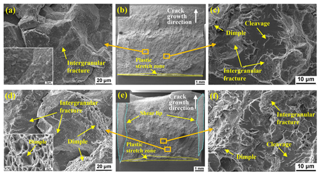
3.3. Fracture Morphology and Crack Growth Path

Figure 8 shows the impact fracture morphology of the WMs in the turbine part and the compressor part. As shown in Figure 8a–c, the dominant fracture mode of the turbine part WM was intergranular fracture as well as a little cleavage and dimples. Figure 8d–f show that the fracture mode of the compressor part WM was intergranular fracture, as well as some cleavage and dimples. The area ratio of intergranular fracture in the turbine part WM (about 85%) was higher than that in the compressor part WM (about 65%). As shown in Figure 8b,e, the plastic stretch zone of the turbine part WM specimen was very narrow and there was nearly no shear lip, while the plastic stretch zone and shear lip of the compressor part WM were larger. Therefore, the impact toughness of the turbine part WM was lower than that of the compressor part WM. The presence of intergranular fracture indicates that the grain boundary cohesive strength decreased significantly and was lower than the cleavage strength and yield strength of grains [18]. The decrease of grain boundary cohesive strength might be the main reason for the poor toughness of the WMs, especially the turbine part WM.
Figure 9 shows the impact fracture morphology of the HAZs. As shown in Figure 9a–c, the fracture morphology of the turbine part HAZ was mainly dimples, as well as a little cleavage, suggesting that the dominant fracture mode was ductile fracture. As shown in Figure 9d–f, the fracture mode of the compressor part HAZ was ductile fracture, with lots of dimples. The plastic stretch zone and shear lip of the HAZs were large. Therefore, the impact toughness of the turbine part HAZ and the compressor part HAZ was high, and the latter was higher than the former. In addition, no intergranular morphology was found, indicating that the grain boundary cohesive strength was still higher than the cleavage strength and yield strength of the grains [18].
The mixed morphology of intergranular fracture, cleavage, and dimples in the WM specimens might be owing to the inhomogeneous microstructure. To correlate the fracture mode and the microstructure of the WMs, the crack growth path and corresponding fracture morphology of the impact specimen in the turbine part WM were analyzed. The crack grew in a transgranular manner in the upper part of columnar zone (see in Figure 10b–d), but in an intergranular manner in the lower part of columnar zone (see in Figure 10e–g) and the interlayer zone (see in Figure 10h–j). The difference in the crack growth mode was related to PAG boundaries. As shown in Figure 10f,i, the secondary cracks distributed along the PAG boundaries indicated that the intergranular fracture occurred along the PAG boundaries. Nevertheless, for the upper part of the columnar zone with few PAG boundaries, the crack grew in a transgranular manner (Figure 10c).

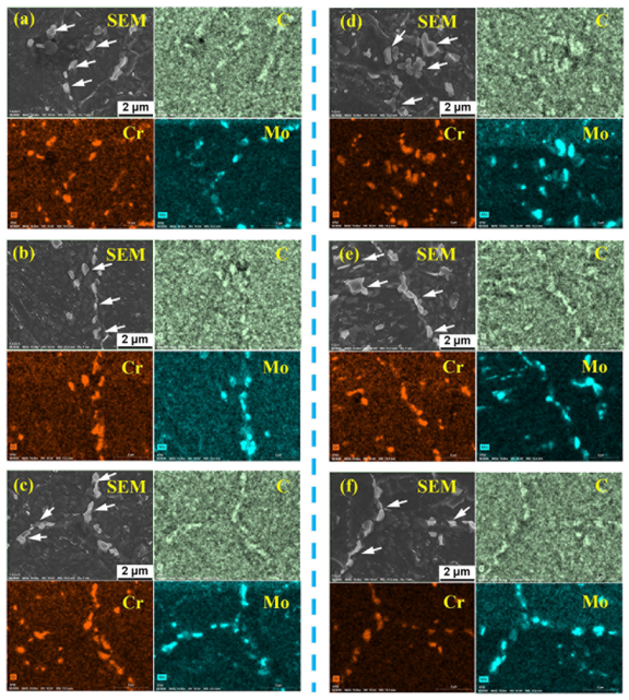
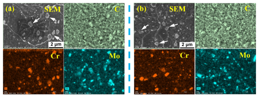
3.4. Element Distribution at Grain Boundaries and Its Effects on Toughness

3.4.1. P Segregation at PAG Boundaries

Intergranular fracture may be caused by the segregation of impurity elements at PAG boundaries. To analyze the segregation of impurity elements in WMs and HAZs, AES analysis was used. The fracture morphology of AES specimens in the WMs was mainly intergranular fracture, while the fracture morphology of AES specimens in the HAZs was dimples and cleavage. As shown in Figure 11, obvious P segregation at the PAG boundaries was found in the WMs. The P concentration segregated at PAG boundaries was calculated according to the method in literature [16,17,18,19]. A total of 10–15 zones in the PAG boundaries were analyzed for each specimen, and the average value was taken as the final segregation concentration. The final concentration of P at the PAG boundaries in the turbine part WM (20.5 at.%) was higher than that in the compressor part WM (13.2 at.%). The concentration of P at PAG boundaries in the HAZs was not obtained, because there was no intergranular fracture surface in the AES specimens. The dimples and cleavage morphology in the AES specimens of the HAZs indicated that the grain boundary cohesive strength was still high and the segregation level of P in the HAZs was slight.
The segregation of P decreases the grain boundary cohesion [17,18]. Therefore, the poor toughness of the WMs and intergranular cracking was caused by the high segregation level of P at PAG boundaries. Additionally, the obvious difference in toughness between the turbine part WM and the compressor part WM was mainly due to the different level of segregation of P. Nakata H et al. [21] found that the fracture mode changed from transgranular fracture to intergranular fracture at the P/Fe peak height ratio of 0.14 for low-alloy steels. The P/Fe peak height ratio refers to (height of P peak)/(height of Fe peak) of the Auger electron spectrum, which was used to roughly evaluate the segregation level of P in low-alloy steels [21]. Islam M A et al. [22] pointed out that the area fraction of intergranular fracture increased and the toughness decreased as P segregation level increased for 2.25Cr-1Mo steels. Song SH et al. [17,18] found that FATT50 increased linearly with increasing P segregation level in CrMo and NiCrMo steels. In this research, the segregation level of P in the turbine part WM was higher than that in the compressor part WM, resulting in a lower grain boundary cohesive strength in the turbine part WM than in the compressor part WM. Therefore, the impact energy of the former (15 J) was much lower than that of the latter (38 J), and FATT50 of the former (138 °C) was much higher than that of the latter (38 °C).
In addition, there were two special phenomena to be explained. (1) P atoms would not diffuse at temperatures below 300 °C, but significant segregation of P occurred in the compressor part WM when in service below 300 °C. (2) The toughness of the HAZs was still high and the segregation of P was slight in the turbine part HAZ when serving at temperatures of 500–540 °C. In the discussion below, these phenomena will be discussed in detail.

3.4.2. P Segregation in the WMs

The high segregation level of P in the compressor part WM might be related to the welding thermal cycle and post-weld heat treatment (PWHT) before service. The CrMoV steel welded rotor was manufactured by welding and then subjected to the PWHT to release residual stress. The multi-layer and multi-pass welding process and the accompanying rapid cooling after welding lead to obvious non-equilibrium segregation of P [23,24,25]. Subsequently, the PWHT was conducted at 600 °C for 20 h, and then the specimen was cooled to about 300 °C at a slow cooling rate (about 10 °C/h), which mainly caused obvious equilibrium segregation of P [24,25,26]. PWHT was the dominant process affecting the final segregation level of P [25]. Therefore, significant segregation of P in the compressor part WM was caused by the non-equilibrium and equilibrium segregation occurring during rapid cooling after welding and PWHT.
The chemical composition, welding, and PWHT process of the turbine part were the same as those of the compressor part, so the segregation level of P in the two parts before service was identical. The final segregation concentration of P in the turbine part WM (20.5 at.%) was higher than that in the compressor part WM (13.2 at.%). Because the segregation that occurred during the PWHT process did not reach the maximum equilibrium segregation level of P. Therefore, P continued to segregate at the PAG boundaries during service at 500–540 °C through equilibrium segregation. Therefore, the final segregation concentration of P in the turbine part WM consisted of the non-equilibrium and the equilibrium segregation occurring during fast cooling after welding, PWHT, and long-term service at 500–540 °C. Therefore, the segregation concentration of P was higher in the turbine part WM than that in the compressor part WM.
In addition, the equilibrium segregation concentration (Ceq) of P at PAG boundaries in iron was estimated according to McLean’s segregation model [27,28],
C e q = C b   exp ( Δ G / R T ) 1 + C b   exp ( Δ G / R T )
where Cb is the matrix concentration of the solute element, ΔG is the free energy change associated with segregation, T is the absolute temperature, and R is the gas constant. The P concentration in matrix (Cb(P)) of the WMs is 0.011 wt.% in weight and 0.020 at.% in atomic. According to the data provided in the literature [27,28], the P segregation free energy Δ G (P) at 500 °C and 540 °C are 43   KJ · mol 1 and 42   KJ · mol 1 , respectively. R = 8.314   J · ( mol · K ) 1 . Calculated according to Equation (1), the equilibrium segregation concentration C e q (P) of the WMs was 13.9 at.% at 500 °C and 9.1 at.% at 540 °C. Generally, the model was in good agreement with the experimental data [27,28]. However, the segregation concentration of P in the turbine part WM (20.5 at.%) was higher than the C e q ( P ) estimated by McLean’s model. This might be related to the inhomogeneous microstructure of the WMs (see in Figure 2). P tended to segregate at the PAG boundaries and there were little PAG boundaries in the upper part of columnar zone (see in Figure 2d,g). Therefore, P atoms in the upper part of columnar zone would diffuse to the PAG boundaries in the adjacent lower part of the columnar zone (see in Figure 2e,h) and the adjacent interlayer zone (see in Figure 2f,i) during service at 500–540 °C. The service time (14 years) was sufficient to achieve the full segregation of P at the PAG boundaries, because the time to achieve the maximum equilibrium segregation level of P at 500 °C is only thousands of hours [27,28]. Finally, the actual segregation concentration of P in the turbine part WM exceeded the C e q ( P ) estimated by McLean’s segregation model. In other words, the inhomogeneous microstructure of the WMs aggravated the segregation of P at the PAG boundaries.

3.4.3. High Toughness of the HAZs

The main differences between the WMs and the HAZs were the element content and the PAG sizes. Therefore, the high toughness of the HAZs might be due to the low impurity element content and the small PAG sizes. Watanabe et al. [29] proposed an empirical factor J to assess the sensitivity of steels to temper embrittlement:
J = ( Mn + Si ) · ( P + Sn ) · 10 4
J was a dimensionless factor related to the content of specified elements in wt.%. The susceptibility to temper embrittlement increased as J increased. For the low-alloy Cr-Mo steels, when J exceeded 100, temper embrittlement would occur under embrittlement conditions [29,30]. The content of Mn, Si, and P in WMs was 1.37, 0.53, and 0.011 wt.%, respectively. The content of Mn, Si, and P in HAZs was 0.42, 0.19, and 0.004 wt.%, respectively. The content of Sn both in the WMs and HAZs was not detected, and was set as 0 wt.%. Calculated according to Equation (2), the values of J in the WMs and the HAZs were 209 and 24, respectively. Therefore, temper embrittlement caused by P segregation at PAG boundaries occurred in the WMs, but not in the HAZs.
It should be noted that the J-factor was an empirical factor with limited accuracy. Therefore, another commonly used empirical factor X [31,32] for evaluating temper embrittlement susceptibility of steels was also introduced to improve accuracy:
X = ( 10 P + 5 Sb + 4 Sn + As ) / 100
X is a dimensionless factor related to the content of the specified elements in ppm. According to Equation (3), the X of the WM is 11, wh ile the X of the HAZ is 4. For low-alloy Cr-Mo steels, when X exceeds 10, temper embrittlement will generally occur under embrittlement conditions [31,32]. Therefore, temper embrittlement caused by the segregation of P occurred in the WM, but not in the HAZ.
In addition, the grain size is another significant factor affecting temper embrittlement [28,33,34]. The larger the size of the PAGs, the smaller the grain boundary area available for P segregation. The grain size of the HAZs was only about 3–7 μm and the grain boundary area available for P segregation was large. Therefore, it was not sufficient to achieve the critical amount of P monolayers needed to cause the temper embrittlement. Therefore, the toughness of the turbine part HAZ did not decrease significantly after serving at 500–540 °C for 14 years. Additionally, as is well known, fine grains could improve the strength and the toughness of steels [9]. Therefore, the toughness of the HAZs was high due to the toughening of fine grains.

4. Conclusions

The microstructure and the toughness of the weld metals (WMs) and heat-affected zones (HAZs) in the turbine part and the compressor part of a low-alloy CrMoV steel gas turbine rotor after 14 years of service were investigated. The turbine part was in service at 500–540 °C, while the compressor part was in service below 300 °C. On the basis of our results, our conclusions are as follows:
(1)
Compared with the compressor part WM and HAZ, there was no obvious difference in microstructure of the turbine part WM and HAZ, indicating that the microstructure in the turbine part WM and HAZ did not significantly degrade during service at 500–540 °C for 14 years.
(2)
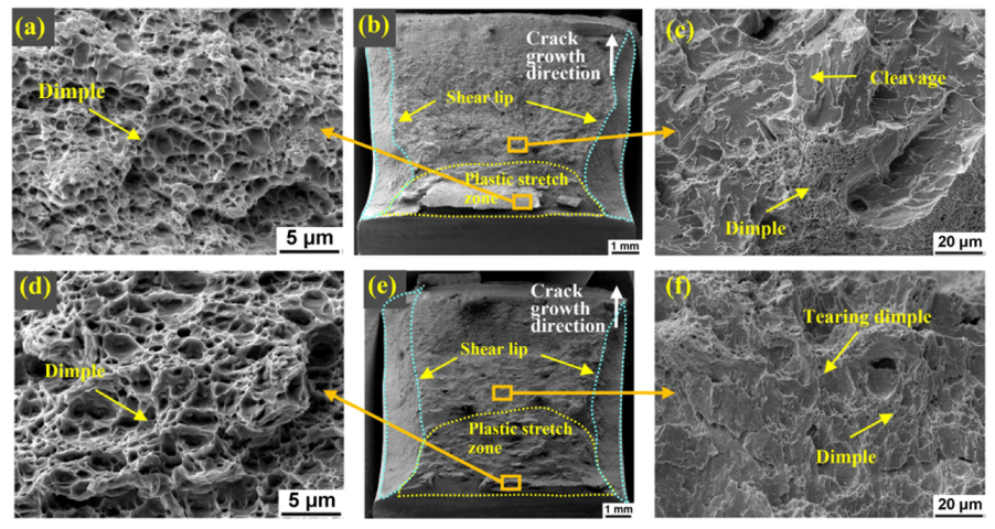
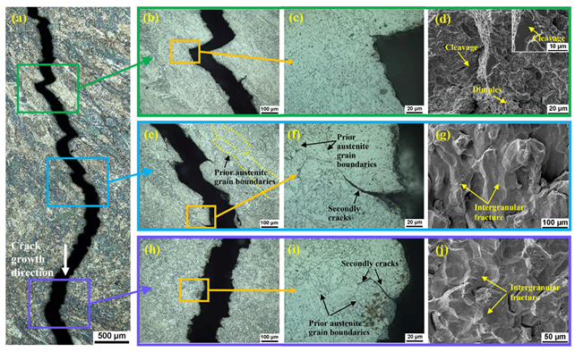
The impact toughness of the WMs with intergranular fracture morphology was much lower than that of the HAZs with dimple morphology, suggesting that the WMs were the weak positions of this rotor. Compared to the compressor part WM (38 J), the impact energy of the turbine part WM (15 J) decreased by 61%, and the FATT50 increased from 38 °C to 138 °C.
(3)
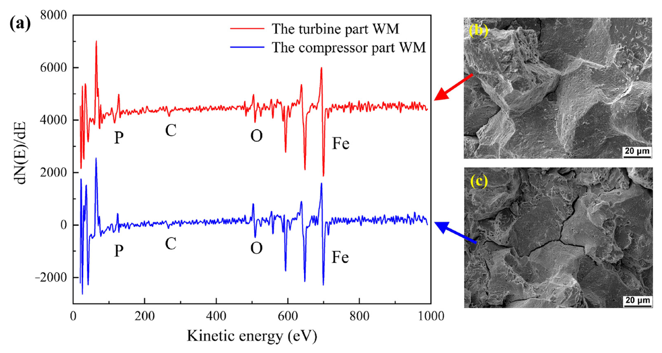
The low toughness in the WMs was due to the significant segregation of P at the prior austenite grain (PAG) boundaries in the turbine part WM (20.5 at.%) and the compressor part WM (13.2 at.%). The segregation of P decreased the toughness of the WMs, especially the turbine part WM. The segregation of P in the compressor part WM occurred during welding and post-weld heat treatment (PWHT), while the segregation of P in the turbine part WM occurred during welding, PWHT, and service at 500–540 °C. Additionally, the inhomogeneous microstructure in WMs would have aggravated the segregation of P.
(4)
The high impact energy in both the compressor part HAZ (177 J) and the turbine part HAZ (156 J) was mainly due to fine grains. In addition, the P element content in the HAZs was low, and the grain boundary area available for P segregation was large. Therefore, the segregation level of P at the PAG boundaries was low, and had little adverse effect on impact toughness.

Author Contributions

Conceptualization, Q.S.; Formal analysis, Q.S., X.L., K.L. and S.L.; Funding acquisition, K.L. and Z.C.; Methodology, Q.S., X.L., K.L., Z.C., J.P. and D.G.; Resources, K.L., Z.C. and D.G.; Validation, K.L., Z.C. and J.P.; Writing—original draft, Q.S.; Writing—review & editing, Q.S., X.L. and C.H. All authors have read and agreed to the published version of the manuscript.

Funding

This research was funded by the National Natural Science Foundation of China (No. 51901113 and 51775300).

Institutional Review Board Statement

Not applicable.

Informed Consent Statement

Not applicable.

Data Availability Statement

Data are contained within the article.

Acknowledgments

The authors are grateful for Rong Wang and Wenyan Yang, Senior Engineers in the State Key Laboratory of Tribology. They helped us finish the SEM and EDX experiments.

Conflicts of Interest

The authors declare no conflict of interest.

References

  1. Cheruvu, N.S. Degradation of mechanical properties of Cr-Mo-V and 2.25Cr-1Mo steel components after long-term service at elevated temperatures. Metall. Trans. A 1989, 20, 87–97. [Google Scholar] [CrossRef]
  2. Joarder, A.; Sarma, D.S.; Cheruvu, N.S. Effect of long-term service exposure on microstructure and mechanical properties of a CrMoV steam turbine rotor steel. Metall. Trans. A 1991, 22A, 1811–1820. [Google Scholar] [CrossRef]
  3. Cheruvu, N.S.; Seth, B.B. The influences of impurity content, tensile strength, and grain size on in-service temper embrittlement of CrMoV steels. Metall. Trans. A 1989, 20A, 2345–2354. [Google Scholar] [CrossRef]
  4. Zhao, S.Q.; Lin, F.S. Mechanical Properties of 30Cr1Mo1V HP-IP Rotor Steel After Long-term Service. J. Chin. Soc. Power Eng. 2012, 32, 414–419. [Google Scholar]
  5. Han, L.-Z.; Gu, J.-F.; Pan, J.-S. Microstructure investigation of Cr-Mo-V steel steam turbine rotor after long-term service. Heat Treat. Met. 2011, 36, 28–32. [Google Scholar]
  6. Ji, D.-M.; Sun, J.Q.; Sun, Q.; Guo, H.-C.; Ren, J.-x.; Zhu, Q.-j. Optimization of Start-up Scheduling and Life Assessment for a Steam Turbine. Energy 2018, 160, 19–32. [Google Scholar] [CrossRef]
  7. Xia, L.; Cai, Z.; Yang, S.; Feng, K.; Li, Z. Characterization on the Microstructure Evolution and Toughness of TIG Weld Metal of 25Cr2Ni2MoV Steel after Post Weld Heat Treatment. Metals 2018, 8, 160. [Google Scholar] [CrossRef] [Green Version]
  8. Swaminathan, V.P.; Viswanathan, R.; Clark, C.P. Material Property Studies of Two High-Pressure Turbine Rotors for Remaining Life Assessment. J. Eng. Mater. Technol. 1994, 116, 19–26. [Google Scholar] [CrossRef]
  9. Guo, Q.; Lu, F.; Xia, L.; Yang, R.; Cui, H.; Gao, Y. Correlation of microstructure and fracture toughness of advanced 9Cr/CrMoV dissimilarly welded joint. Mater. Sci. Eng. A 2015, 638, 240–250. [Google Scholar] [CrossRef]
  10. Zhu, M.-L.; Xuan, F.-Z. Effects of temperature on tensile and impact behavior of dissimilar welds of rotor steels. Mater. Des. 2010, 31, 3346–3352. [Google Scholar] [CrossRef]
  11. Li, X.; Li, K.; Li, S.; Wu, Y.; Cai, Z.; Pan, J. Microstructure and high-temperature fracture toughness of NG-TIG welded Inconel 617B superalloy. J. Mater. Sci. Technol. 2020, 39, 173–182. [Google Scholar] [CrossRef]
  12. Yan, Y.-M.; Hu, Z.-F.; Lin, F.-S.; Zhao, S.-Q. Fracture and fatigue properties of 30Cr1Mo1V rotor after long-term service and its microstructure evolution. Trans. Mater. Heat Treat. 2013, 34, 60–63. [Google Scholar]
  13. Golański, G.; Pietryka, I.; Słania, J.; Mroziński, S.; Jasak, J. Microstructure and mechanical properties of CrMoV steel after long-term service. Arch. Metall. Mater. 2016, 61, 51–54. [Google Scholar] [CrossRef]
  14. Guo, X.; Zhao, L.; Liu, X.; Lu, F. Investigation on the resistance to fatigue crack growth for weld metals with different Ti addition in near-threshold regime. Int. J. Fatigue 2019, 120, 1–11. [Google Scholar] [CrossRef]
  15. ISO 148-1; Metallic Materials—Charpy Pendulum Impact Test—Part 1: Test Method. ISO: Geneva, Switzerland, 2006.
  16. Wu, J.; Song, S.H.; Weng, L.Q.; Xi, T.H.; Yuan, Z.X. An Auger electron spectroscopy study of phosphorus and molybdenum grain boundary segregation in a 2.25Cr1Mo steel. Mater. Charact. 2008, 59, 261–265. [Google Scholar] [CrossRef]
  17. Song, S.H.; Zhuang, H.; Wu, J.; Weng, L.Q.; Yuan, Z.X.; Xi, T.H. Dependence of ductile-to brittle transition temperature on phosphorus grain boundary segregation for a 2.25Cr1Mo steel. Mater. Sci. Eng. A 2008, 486, 433–438. [Google Scholar] [CrossRef]
  18. Wang, K.; Guo, Y.; Song, S. Quantitative dependence of ductile-to-brittle transition on phosphorus grain boundary segregation for a novel Ni-Cr-Mo RPV steel. J. Mater. Res. Technol. 2021, 15, 6404–6414. [Google Scholar] [CrossRef]
  19. Davis, L.E.; Macdonald, N.C.; Palmberg, P.W.; Riach, G.E.; Weber, R.E. PHI Handbook of Auger Electron Spectroscopy; Perkin-Elmer Corporation: Eden Prairie, MN, USA, 1976. [Google Scholar]
  20. Katsuyama, J.; Tobita, T.; Nishiyama, Y.; Onizawa, K. Mechanical and Microstructural Characterization of Heat-Affected Zone Materials of Reactor Pressure Vessel. Press. Vessel. Technol. 2012, 134, 031402. [Google Scholar] [CrossRef]
  21. Nakata, H.; Fujii, K.; Fukuya, K.; Kasada, R.; Kimura, A. Grain Boundary Phosphorus Segregation in Thermally Aged Low Alloy Steels. J. Nucl. Sci. Technol. 2006, 43, 785–793. [Google Scholar] [CrossRef]
  22. Islam, M.A.; Knott, J.F.; Bowen, P. Critical Level of Intergranular Fracture to Affect the Toughness of Embrittled 2.25Cr-1Mo Steels. J. Mater. Eng. Perform. 2004, 13, 600–606. [Google Scholar] [CrossRef]
  23. Vorlicek, V.; Flewitt, P.E.J. Cooling induced segregation of impurity elements to grain boundaries in Fe-3 wt%Ni alloys, 214wt%Cr-1 wt%Mo steel and submerged arc weld metal. Acta Metall. Mater. 1994, 42, 3309–3320. [Google Scholar] [CrossRef]
  24. Zhai, Z.; Miyahara, Y.; Abe, H.; Watanabe, Y. Effects of Thermal History and Microstructure on Segregation of Phosphorus and Alloying Elements in the Heat-Affected Zone of a Low Alloy Steel. Metall. Mater. Trans. A 2014, 45, 6163–6172. [Google Scholar] [CrossRef]
  25. Maier, P.; Faulkner, R.G. Effects of thermal history and microstructure on phosphorus and manganese segregation at grain boundaries in C-Mn welds. Mater. Charact. 2003, 51, 49–62. [Google Scholar] [CrossRef]
  26. Zhao, Y.; Ma, Q.; Song, S. Hardening Embrittlement and Non-Hardening Embrittlement of Welding-Heat-Affected Zones in a Cr-Mo Low Alloy Steel. Metals 2018, 8, 405. [Google Scholar] [CrossRef] [Green Version]
  27. Vatter, I.A.; Hippsley, C.A.; Druce, S.G. Review of thermal ageing data and its application to operating reactor pressure vessels. Int. J. Press. Vessel. Pip. 1993, 54, 31–48. [Google Scholar] [CrossRef]
  28. Zhao, Y.; Song, S. Combined Effect of Phosphorus Grain Boundary Segregation, Yield Strength, and Grain Size on Embrittlement of a Cr–Mo Low-Alloy Steel. Steel Res. Int. 2018, 89, 1800096. [Google Scholar] [CrossRef]
  29. Watanabe, J.; Shindo, Y.; Murakami, Y. Temper embrittlement of 2-1/4 Cr-1Mo pressure vessel steel. In Proceedings of the ASME 29th Petroleum Mechanical Engineering Conference, Dallas, TX, USA, 15–18 September 1974. [Google Scholar]
  30. Roberto, R.; Michela, F. On the Step Cooling Treatment for the Assessment of Temper Embrittlement Susceptibility of Heavy Forgings in Superclean Steels. Metals 2016, 6, 239. [Google Scholar] [CrossRef] [Green Version]
  31. Mcgrath, J.T.; Chandel, R.S.; Orr, R.F.; Gianetto, J.A. A Review of Factors Affecting the Structural Integrity of Weldments in Heavy Wall Reactor Vessels. Can. Metall. Q. 2013, 28, 75–83. [Google Scholar] [CrossRef]
  32. Bruscato, R. Temper Embrittlement and Creep Embrittlement of 2.25%Cr–1%Mo shielded metal arc weld deposits. Weld. J. 1973, 49, 148–156. [Google Scholar]
  33. Ding, R.G.; Rong, T.S.; Knott, J.F. Phosphorus segregation in 2.25Cr–1Mo steel. Met. Sci. J. 2013, 21, 85–92. [Google Scholar] [CrossRef]
  34. Bulloch, J.H.; Hickey, J.J. Reverse temper embrittlement of turbine bolts during an outage. Theor. Appl. Fract. Mech. 1994, 20, 141–147. [Google Scholar] [CrossRef]
Figure 1. Gas turbine rotor and toughness test sampling: (a) the actual rotor after 14 years of service and its three parts; (b) the materials cut from the turbine part and the compressor part; (c,d) the sampling process and the dimensions (in mm) of the standard Charpy V-notch impact test specimens.
Metals 12 00278 g001
Figure 2. Microstructure of the turbine part WM: (b) the entire microstructure of the WM; (a) the columnar zone; (d,g) the upper part of columnar zone; (e,h) the lower part of columnar zone; (c,f,i) the interlayer zone.
Metals 12 00278 g002
Figure 3. Microstructure of the compressor part WM: (b) the entire microstructure of the WM; (a) the columnar zone; (d,g) the upper part of columnar zone; (e,h) the lower part of columnar zone; (c,f,i) the interlayer zone.
Metals 12 00278 g003
Figure 4. Microstructure of the turbine part HAZ: (a) the entire microstructure of the HAZ; (bd) the microstructure of FGHAZ; (e) the inverse pole figure of EBSD in the FGHAZ.
Metals 12 00278 g004
Figure 5. Microstructure of the compressor part HAZ: (a) the entire microstructure of the HAZ; (bd) the microstructure of FGHAZ; (e) the inverse pole figure of EBSD in the FGHAZ.
Metals 12 00278 g005
Figure 6. Carbides in the WMs: (ac) the turbine part; (df) the compressor part; (a,d) the upper part of the columnar zone; (b,e) the lower part of the columnar zone; (c,f) the interlayer zone. The white arrows point to carbides.
Metals 12 00278 g006
Figure 7. Carbides in the FGHAZs: (a) the turbine part; (b) the compressor part. The white arrows point to carbides.
Metals 12 00278 g007
Figure 8. The impact fracture morphology of the WMs: (ac) the turbine part (15 J); (df) the compressor part (38 J).
Metals 12 00278 g008
Figure 9. The impact fracture morphology of the HAZs: (ac) the turbine part (156 J); (df) the compressor part (177 J).
Metals 12 00278 g009
Figure 10. The crack growth path and the fracture morphology of the impact specimen in the turbine part WM: (a) the crack growth path; (bd) the upper part of columnar zone; (eg) the lower part of columnar zone; (hj) the interlayer zone.
Metals 12 00278 g010
Figure 11. The Auger analysis results of the WMs: (a) Auger electron spectroscopy; (b) the fracture surface of AES specimens in the turbine part WM; (c) the fracture surface of AES specimens in the compressor part WM. The C and O peaks were due to the contamination in the AES chamber.
Metals 12 00278 g011
Table 1. Chemical composition of BMs and WMs in the turbine part and the compressor part (wt.%).
ElementCCrMoNiMnVSiPSCuPbFe
BM (HAZ)0.201.320.920.660.420.280.190.0040.0010.110.04balance
WM0.091.660.890.131.370.040.530.0110.0090.120.03balance
Table 2. Impact energy and FATT50 of the WMs and HAZs in the turbine part and the compressor part.
Parts of the RotorZones of the JointImpact Energy at 25 °C (J)FATT50 (°C)
The turbine partWM15138
HAZ156\
The compressor partWM3838
HAZ177\
Publisher’s Note: MDPI stays neutral with regard to jurisdictional claims in published maps and institutional affiliations.

