Article

Residual Stress Properties of the Welded Thick Underwater Spherical Pressure Hull Based on Finite Element Analysis

1
Shanghai Engineering Research Center of Marine Renewable Energy, College of Engineering Science and Technology, Shanghai Ocean University, Shanghai 201306, China
2
Shanghai Engineering Research Center of Hadal Science and Technology, Shanghai Ocean University, Shanghai 201306, China
3
Project Management Office of China National Scientific Observatory, Tongji University, Shanghai 200092, China
4
Baoji Titanium Industry Co., Ltd., Baoji 721014, China
*
Authors to whom correspondence should be addressed.
Metals 2022, 12(11), 1958; https://doi.org/10.3390/met12111958
Submission received: 24 September 2022 / Revised: 10 November 2022 / Accepted: 11 November 2022 / Published: 16 November 2022
(This article belongs to the Special Issue Studies on Fatigue Behavior of Engineering Material and Structures)

Abstract

:
Residual stress inevitably occurs at the weld in the process of manufacturing thick pressure hulls for manned submersibles, which affects the bearing capacity of the hull. In this study, an electron-beam-welded 32 mm-thick Ti-6Al-4V plate specimen is first tested, then the measured data of residual stress distribution is applied to validate the accuracy of the simulation method. Accordingly, three-dimensional numerical analysis on the equator welding by electron beam method of a 32 mm-thick Ti-6Al-4V spherical pressure hull is conducted to obtain the variation tendency of residual stress during the welding process. The results indicate that both compressive and tensile stresses exist along the weld path on the outer surface of the hull comparing to total tensile stresses on the inner surface. The maximum tensile stress that occurs on the inner surface approximates to 850 MPa, which is almost equivalent to the yield stress of the material. Based on the acceptance criterion that the peak value of residual stress due to weld technique is restricted to be less than 40% of the material yield strength in room temperature, post-weld heat treatment must be performed. Simulation on post-weld heat treatment for optimizing process parameters can be done by taking the results of welding simulation in the present study as input.

1. Introduction

Manned and unmanned submersibles and other fixed and mobile ocean observation platforms are crucial for deep-sea resource exploration [1]. Spherical pressure hulls are the main components and pressure-bearing units in such equipment [2], and ensuring the strength and structural integrity of spherical pressure hulls is key for long-term safety of the equipment [3,4]. Titanium alloys have been widely applied in deep-sea spherical pressure hulls because they have high tensile strength, corrosion resistance, toughness, anti-fatigue performance, and good welding performance [5]. Most of the spherical pressure hulls of submersibles presently in service are made of titanium alloys [6]. The manufacturing of spherical pressure hulls generally involves welding together several large petal-shaped pieces or two hemispheres [7]. Some spherical pressure hulls, such as the manned cabin of a 4500 m-class submersible, contain 9 to 11 welds [8]. Spherical pressure hulls manufactured through the welding of hemispherical parts, such as the manned cabins of 11,000 m-class submersibles made in China [9], contain numerous welds at the observation windows, access openings, and through-thickness penetrating panels (Figure 1). Welding deformation and residual stress inevitably affect the mechanical properties of the structures of such hulls [10,11,12]. Residual stress properties such as the normalized peak value, tension/compression state, direction and existence position, and the distribution of the residual stresses due to welding on thick spherical hull made of Ti-6Al-4V must be paid attention to.
High-temperature heat treatment can improve the strength of a weld [13] and eliminate some residual stress. However, when high-temperature heat treatment is used in welding a spherical pressure hull, it may deform the hull, thus negatively affecting the hull’s overall performance [14]. Initial geometric deformation, welding residual stress, heat treatment temperature, material creep during insulation, and even the gravity of the pressure hull itself affect the degree of deformation resulting from heat treatment [15]. So, for the thick pressure hull with large dimension and openings, high temperature heat treatment after welding must be done carefully. Before doing this, it is necessary to evaluate the magnitude of welding residual stress to see if it is within the acceptable range, as heat treatment and welding are consecutive processes and should be arranged sequentially in a simulation. Although welding simulation has been thoroughly explored in previous studies [16], only some preliminary studies have explored simulations for thick spherical pressure hulls made of high-strength titanium alloys [17]. Xu et al. performed a numerical simulation of the welding residual stress in a Ti-6Al-4V spherical pressure hull with an internal diameter of 500 mm [18] and a thickness of approximately 9.6 mm and assessed the effect of the residual stress on the ultimate tensile strength of the hull. Li et al. studied the residual stress in a Ti80 spherical pressure hull with a thickness of 56 mm after wire-filling arc welding. Published results of simulations performed on titanium alloy hulls have remained limited [17]. Zhang et al. performed a numerical simulation of and experimental research on using the external pressure method to adjust the welding residual stress in a spherical pressure hull [19]; however, the hull was made from Q345 steel, and the heat source and grid size used in the simulation were not mentioned in their report [19]. Liu et al. conducted simulation in ANSYS to predict the residual deformation of a thick spherical pressure hull [20], performed a welding test on a sample, and evaluated the residual stress in and deformation of the hull after welding through thermal–mechanical coupling analysis [20]. However, the use of a Gaussian heat source in their study may have affected the measurement of residual stress. Yu et al. studied the residual stress in and deformation of spherical pressure hulls with different thickness-to-radius ratios during welding and performed a numerical simulation in ABAQUS to explore the underlying mechanisms [21]. However, their study also employed a Gaussian heat source, and reflect that the molten pool effect of the manufacturing material and high-energy electron beam welding heat source is difficult.
Furthermore, few studies have explored the welding properties and analytic methods relevant to the pure electron beam welding of thick titanium alloy spherical pressure hulls. To address this gap in the literature, in the present study, FORTRAN was used to write a DFLUX electron beam heat source subroutine in ABAQUS, and a welding experiment was performed on a thick plate sample with the same thickness as the Ti-6Al-4V spherical pressure hull. DFLUX is a user subprogram. In the heat transfer or mass diffusion analysis, the non-uniform distribution flux can be defined as a function of location, time, temperature, number of elements, integration points, etc. The program will call at each flux integration point for each element-based or surface-based non-uniform distribution flux definition (heat transfer only). First, the welding temperature field of a Ti-6Al-4V plate with a thickness of 32 mm was determined through a pure electron beam welding simulation. Thereafter, a thermal–mechanical coupling analysis was conducted, and the residual stress in and deformation of the plate after welding were calculated. The numerical simulation results were determined to be in good agreement with the experimental results. After validation of the simulation method and modelling parameters for the material, finite element analysis is conducted on the thick spherical pressure hull with residual stress distribution obtained. The changing tendency and the magnitude of the residual stress can provide basis for the subsequent heat treatment research on the whole spherical hull. The results of this study may serve as a reference for the development of high-precision methods for manufacturing titanium alloy spherical pressure hulls.

2. Validation of Simulation Method by Experiment on a 32-Mm-Thick Ti-6Al-4V Plate

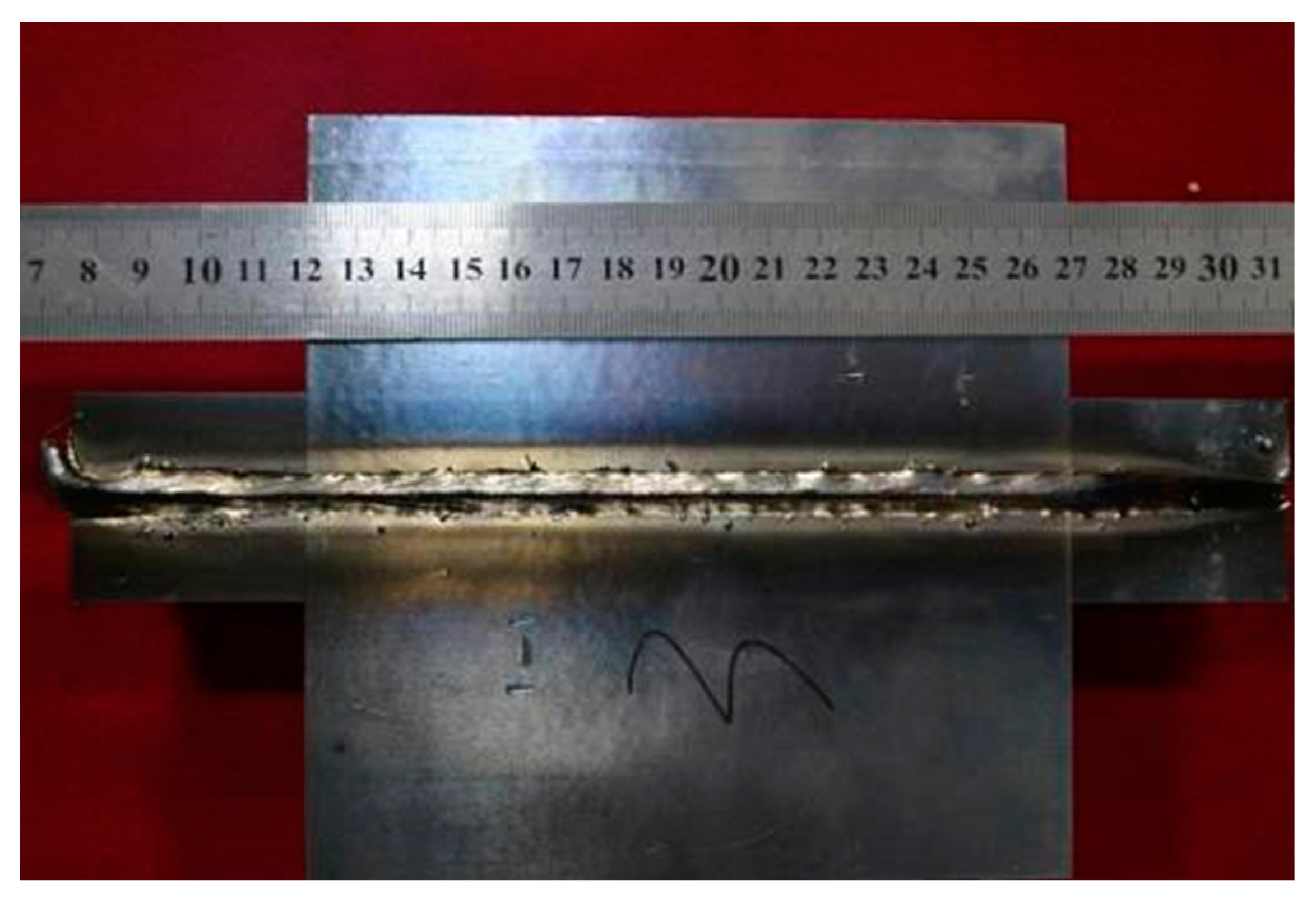
2.1. Experiment on a 32-Mm-Thick Ti-6Al-4V Plate

To avoid the high cost and difficulty of welding test on thick spherical hull, a Ti-6Al-4V plate with the same thickness of 32 mm as the spherical hull under research was conducted to provide basis for validating the simulation method and modelling parameters of the material. The specimen was 150 mm in length, 150 mm in width, and 32 mm in height (Figure 2). In the experiment, the specimen was subjected to pure electron beam welding; the welding voltage and current were set to 20 V and 200 A, respectively.
The welding residual stress was measured using a USGNET ultrasonic stress measurement analyser. The single point test time of the device is <5 s, and when using the high-speed real-time detection mode, data are collected at a rate of 15 times per second. The ultrasonic stress measurement module can improve the echo signal quality through digital and analogue filtering, and analogue filtering can be used to filter frequencies of <1, 2.5, 5, and 10 MHz. The device also contains four stress measurement gates that can be moved and positioned freely. It can accurately select the waveform to be measured to ensure measurement accuracy and can also be used for the high-precision stress measurement of the combined dual gate. The acoustic time resolution of the stress measurement module is ≥2.5 ns, and regarding measurement accuracy, stress measurements are generally within 3% of their actual values.
The following device parameters were applied in the experiment: excitation voltage, 300 V; impedance matching value, 200 ω; filter frequency, 2.5 MHz; probe frequency, 5 MHz; probe wafer diameter, 12 mm; probe incident angle, 24°. The welding residual stress distribution by measurement of seven points along the vertical weld path is shown in Figure 3. The joint was inspected after welding and there were no welding defects beyond the standard.

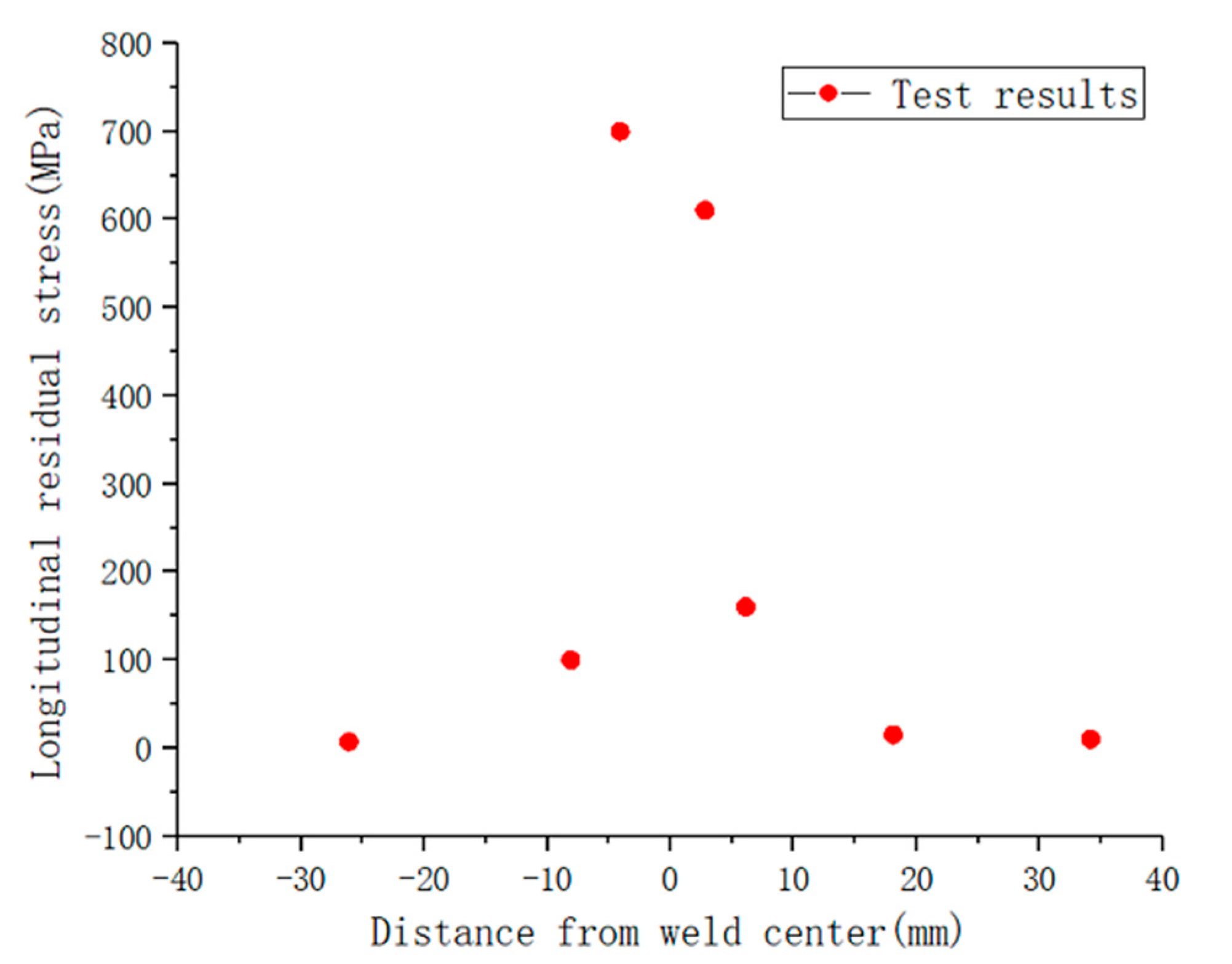
2.2. Validation of Simulation Method by Experiment

In this study, a sequentially coupled thermoelastic–plastic finite element method will be used to simulate the temperature field and stress–strain field of a Ti-6Al-4V plate during the welding process. First, according to the welding parameters and thermal boundary conditions, the moving heat source model was used to calculate the welding temperature field. The temperature history cyclic load of each node was loaded into the same model as the thermal load, and the model was used to calculate the residual stress of the plate. In numerical simulations, the variations of material parameters with temperature as well as the high-temperature thermophysical properties and mechanical properties of materials were considered. A flowchart of the simulation process is presented in Figure 4.

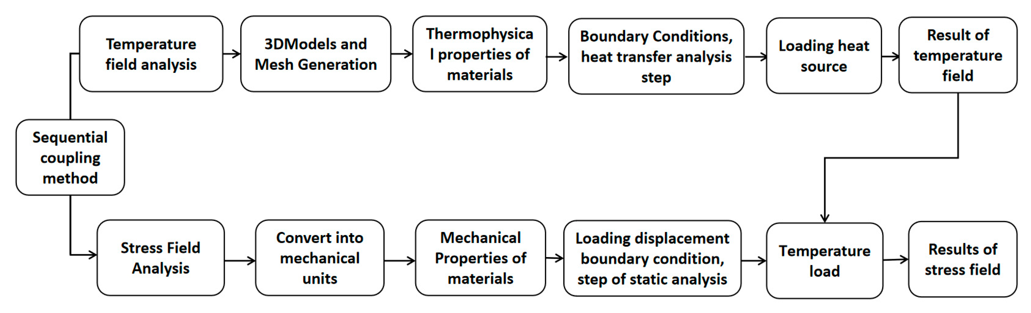
2.2.1. Theoretical Basis of the Simulation

Electron beam welding is a typical nonlinear transient heat conduction problem. The three-dimensional nonlinear transient heat conduction equation is as follows [22]:
ρ c = x λ T x + y λ T y + z λ T z + Q ¯
where r is the density of the material, c is the mass-specific heat capacity of the material, T is the distribution function of the temperature field, and Q ¯ is the intensity of internal heat source. The theoretical basis of the welding stress was elastic–plastic finite element theory. The basic law of welding heat transfer is an expression describing the relationship between a transient temperature field and transient local heat source. As the heat source and local heat input change over time, the heat near the weld is rapidly transferred to areas with lower temperatures, such as the edges of the plate. In this process, heat is lost because of measured heat transfer, mainly in the form of convection and, in the case of vacuum electron beam welding, thermal radiation.
As a high-energy beam welding method, vacuum electron beam welding differs considerably from conventional arc welding. Electron beam welding is characterized by a high energy density and deep thermal penetration. The thermal field around a weld produced through electron beam welding is uneven, resulting in drastic changes in the temperature field gradient near the weld. The most common heat source model used in electron beam welding simulations is the conical heat source model (Figure 5). The temperature field distribution aligns with the outline of the electron beam welding weld, which is shaped like a nail tip. Therefore, the conical heat source model was selected as the heat source model in this study. The conical heat source model is expressed as follows:
Q v = 9 η P π 1 e 3 1 z e z i r e 2 + r e r i + r i 2 exp 3 r 2 r c 2
r c = f ( z ) = r i + ( r e r i ) z z i z e z i
where Q v is the bulk heat flux, P is the laser beam energy, η is the efficiency value, r is the radius function of x and y, r c is the heat distribution coefficient with respect to depth z, r e and r i are the maximum and minimum radii, respectively, and z e and z i are the maximum and minimum values in the z direction, respectively. The thermophysical performance parameters of Ti-6Al-4V obtained by experiments are listed in Table 1.

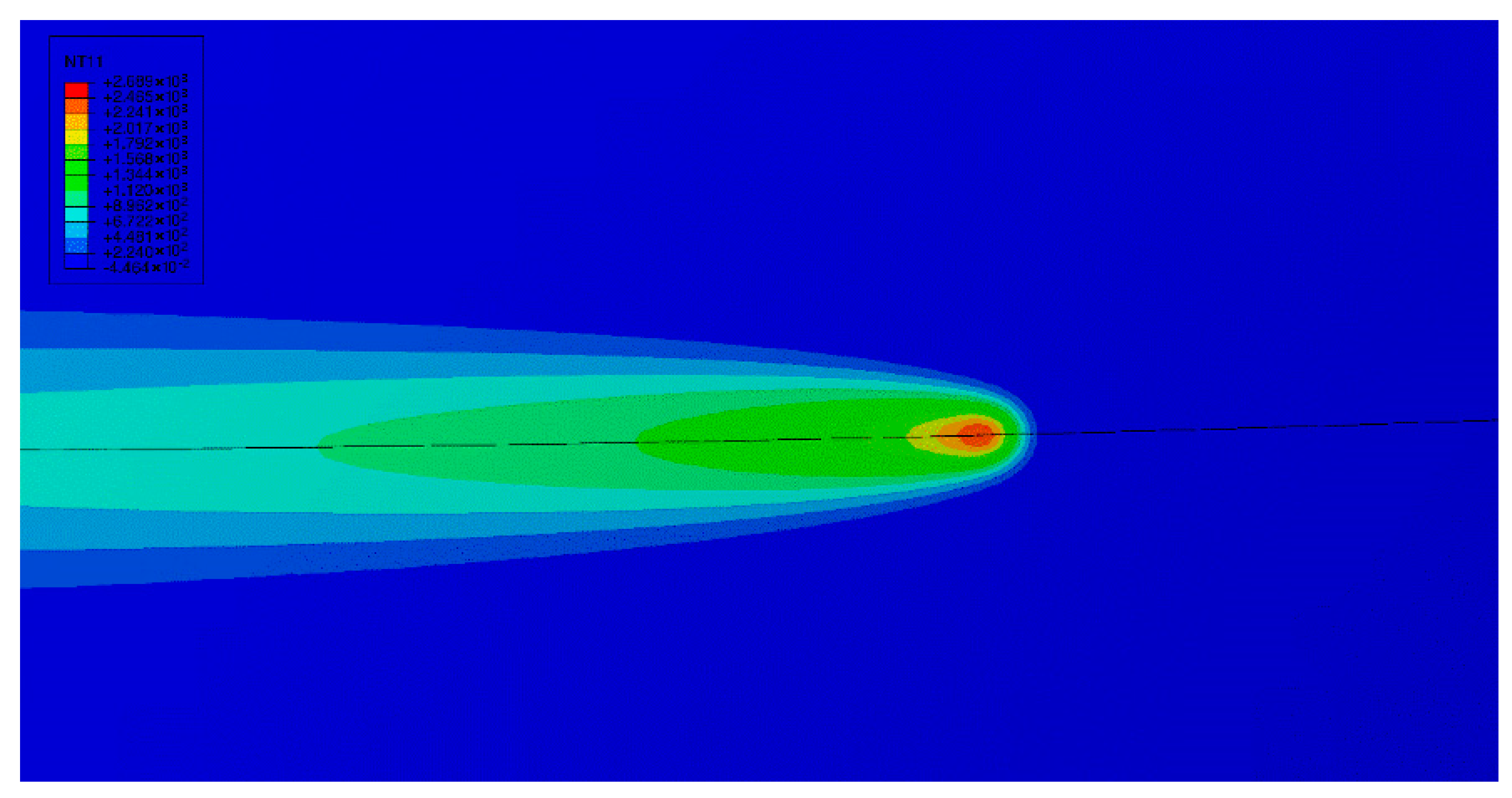
2.2.2. Simulation on a 32 mm-Thick Ti-6Al-4V Plate

Electron beam welding is a type of high-energy beam welding that is characterized by a highly concentrated welding heat source. The radius of the electron beam spot was approximately 0.3 mm. To ensure the accuracy of the calculations, the element size of the geometric model during finite element mesh generation within the range of the welding heat source was necessarily no larger than the radius of the electron beam spot. The mesh size of the weld and the heat-affected area near the weld shown in Figure 6 was 0.5 × 0.5 × 0.5 mm3.
The mesh size at the weld centre is small and being increased with the distance from the weld to improve computational efficiency, and the finite element model was established by symmetrically dividing the plate into halves. The total numbers of nodes and elements in the model were 152,028 and 141,904, respectively. All the elements were hexahedral. The eight-node linear heat transfer element DC3D8 and the eight-node linear element C3D8R in ABAQUS are respectively used for the temperature field and the stress field calculations.
Figure 7 illustrates the shape of weld pool according to the numerical simulation comparing to the experimental result. The light gray part at the right in the figure displays the weld pool when the temperature of the weld is over 1650 °C. The weld pool is shaped like a nail with the width of approximately 1.4 mm. In the actual welding process, the width of the weld pool is generally approximately 1 to 4 mm, and the simulation value is consistent with the measured value.
Figure 8a,b illustrate the temperature field distributions on the weld surface and in the direction perpendicular to the weld, respectively, when t = 6 s, and Figure 8c illustrates the temperature field distribution on the weld surface when t = 10 s. As indicated in the figures, the maximum temperature corresponds to the centre of the welding heat source and changes with the movement of the heat source during the welding process. Because the temperature field gradient in the welding area is large, heat is transferred from the weld centerline to both sides of the plate, and the size of the heat-affected area increases over time. In the area surrounding the electron beam spot, the temperature rapidly reaches approximately 2800 °C. In the areas far from the heat source, the temperature remains unchanged (equivalent to room temperature). Corresponding to the movement of the electron beam spot, the temperature field distribution on the weld surface is a narrow oval. The isotherms in front of the heat source are densely distributed, and the temperature gradient is large. The isotherms behind the heat source are elongated into ellipses, and the isotherm gradient behind the heat source is lower than that in front of the heat source.
Figure 9 presents the thermal cycle curves of nodes selected from positions perpendicular to the weld direction at different distances from the weld centerline. When the heat source moves to the node at the weld centerline, the temperature at the node increases rapidly. The electron beam spot is the area with the highest temperature of the model. Because the maximum temperature (approximately 2800 °C) is much higher than the melting point of titanium alloy, the material in this area melts. The rate of temperature increase decreases as the distance between the node and the weld increases (from 0.00 mm to 7.50 mm), and the corresponding maximum temperature of the node decreases in turn (from approximately 2800 °C at a distance of 0.0 mm to approximately 400 °C at a distance of 7.50 mm). When the welding heat source passes through the selected node, the temperature in the weld centre decreases rapidly, and the temperatures of the areas far from the weld centre still increase, but then decrease slowly. Over time, the temperatures of different areas of plate reach equilibrium and then slowly cool to room temperature.
Figure 10 illustrated the simulation results of stress distribution in the longitudinal direction together with the measured data in the experiment. As indicated in Figure 10, along the vertical weld path (the direction of x-axis), the longitudinal welding residual stress is tensile stress and tends to be symmetrically distributed. The longitudinal residual stress is strongest in and near the weld, with a maximum value of approximately 819 MPa. The longitudinal residual stress decreases rapidly with increasing distance from the weld centre and transforms into compressive stress, with a maximum value of approximately 177 MPa. After peaking, the compressive stress gradually tends to zero. The numerical simulation results are mostly consistent with the experimental results. The modelling parameters obtained through the stress distribution results validated by experiment on a 32 mm-thick plate specimen can be applied for simulation of thick underwater spherical pressure hull made of Ti-6Al-4V.

3. Simulation on the Welded Thick Underwater Spherical Pressure Hull

3.1. Geometric Model and Coordinate Systems

The inner diameter r and thickness d of the spherical pressure hull were 254 mm and 32 mm, respectively, corresponding to a thickness-to-radius ratio of 0.125. The hull was also made of Ti-6Al-4V titanium alloy, and its relevant material parameters were consistent with those of the flat plate (Table 1). A 1/8 spherical pressure hull was used in the simulation. Symmetric boundary conditions were applied. A total of two nodes were selected and used to apply fully fixed boundary conditions in the stress field analysis. The points on the outer surface of the spherical pressure hull that were far from the weld (except the vertex) were fully constrained, and the selected constraint points were not on the same circumference. The mesh size at the weld centre and the surrounding heat-affected area was 0.5 × 0.5 × 0.5 mm3, and the entire model contained 587,013 elements. The eight-node linear heat transfer hexahedral element DC3D8 in ABAQUS was used for the temperature field calculations, and the eight-node linear hexahedral element C3D8R was used for the stress field calculations. The meshing of the spherical pressure hull model is illustrated in Figure 11.
To ensure that the welding heat source would remain constantly aligned with the spherical centre, a coordinate system was established (Figure 12). First, the heat source centre moves circumferentially around the equator weld; then, as illustrated in Figure 13, the heat source is rotated around the y-axis by a certain angle θ, calculated according to the equation θ = v · t R , where ν is the welding speed, t is the welding time, and R = r + d, where r and d are the inner radius and thickness of the spherical hull, respectively.
x = x + R · sin θ
y = y + R · 1 cos θ
The angle between the welding gun and the workpiece θ cannot be ignored in numerical simulations. According to the principle of coordinate transformation, the original coordinate system o(x, y, z) must be rotated around the y-axis by a certain angle α (where α = π 2 θ ), as illustrated in Figure 14, to ensure that the heat source remains constantly aligned with the spherical centre, thus producing a new coordinate system o′(x′, y′, z′). The relationship between the coordinate systems is as follows:
x y z = sin α 0 cos α 0 1 0 cos α 0 sin α x y z

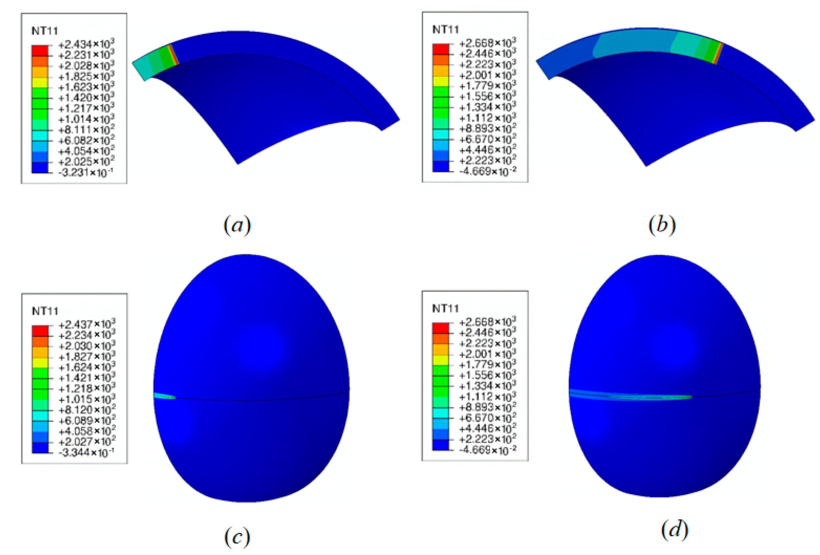
3.2. Simulation Results

Figure 15a,c and Figure 15b,d illustrate the temperature field distributions on the weld surface when t = 4 s and t = 12 s, respectively. Figure 16 illustrates the enlarged temperature field of the spherical pressure hull when t = 12 s. During the welding process, the maximum temperature corresponds to the centre of the welding heat source and changes with the movement of the heat source, and the heat source is constantly aligned with the centre of the equator weld. Because the temperature field gradient in the welding area is large, the heat is transferred from the weld centerline to both sides of the plate, and the size of the heat-affected area increases. In the area surrounding the electron beam spot, the temperature rapidly reaches approximately 2800 °C. In the areas far from the heat source, the temperature remains unchanged (equivalent to room temperature).
The welding temperature field of the spherical pressure hull by numerically simulated was used as the initial predefined field for welding residual stress analysis, which was performed using a sequential coupling method. Transverse welding residual stress is perpendicular to the equator welding direction (radial), and longitudinal welding residual stress occurs along the equator welding direction (circumferential).
According to the numerical simulation of the electron beam welding process, the distributions of welding residual stress in different directions were calculated (Figure 17, Figure 18, Figure 19, Figure 20, Figure 21 and Figure 22). The transverse and longitudinal residual stresses near the weld on the inner surface and the longitudinal residual stresses in the hull were tensile, whereas the transverse residual stress was compressive (Figure 17 and Figure 18). The maximum longitudinal residual tensile stress and transverse residual compressive stress were approximately 590 and 325 MPa, respectively. As indicated in Figure 17 and Figure 18, on the vertical weld path on the inner surface of the spherical pressure hull, the longitudinal residual tensile stress near the weld was greater than the transverse residual tensile stress, and the longitudinal residual stress peaked at approximately 650 MPa, whereas the transverse residual tensile stress peaked at approximately 450 MPa. The residual stress on the vertical weld path on the inner surface of the spherical pressure hull tended to zero. During welding, after the high-energy electron beam melted the welding material, the longitudinal residual stress appeared as high tensile stress at the weld because of cooling shrinkage. This tensile stress gradually decreased with increasing distance from the weld and transformed into compressive stress, tending to 0 MPa in the areas far from the weld. Actually, the status depends on the thermomechanical processing of the material [23].
The longitudinal residual stress on the outer surface of the spherical pressure hull along the weld path was tensile, whereas the transverse residual stress was compressive. The longitudinal and transverse residual stresses in the inner surface along the weld path were tensile, and the longitudinal residual tensile stress was greater than the transverse residual tensile stress. The maximum tensile stress on the inner surface was approximately 850 MPa, almost equivalent to the yield stress of the material. In the design of deep-sea pressure hull, the peak value of residual stress due to weld technique is restricted, which should not be more than 40% of the material yield strength in room temperature. As indicated in Table 1, the yield strength of the material in the room temperature is 895 MPa, so the peak value of the residual stress should be less than 358 MPa. Based on the acceptance criterion, post-weld heat treatment must be performed. Simulation on post-weld heat treatment for optimizing process parameters can be done by taking the results of welding simulation as input.

4. Summary and Conclusions

In this study, an electron-beam weld modelling process validated by the experiment of a plate sample has been established for a thick underwater spherical hull made of Ti-6Al-4V, which is applied to analyze the residual stress distribution of the hull. On the basis of the analysis results, the main conclusions can be drawn as follows:
(1)
The temperature and stress fields on the 32-mm-thick Ti-6Al-4V plate during vacuum electron beam welding were incorporated into a three-dimensional finite element numerical simulation model and the simulation results were mostly consistent with the experimental data, demonstrating that the numerical simulation technique together with input parameters is reasonable and can be applied in future studies on the welding of Ti-6Al-4V spherical pressure hulls.
(2)
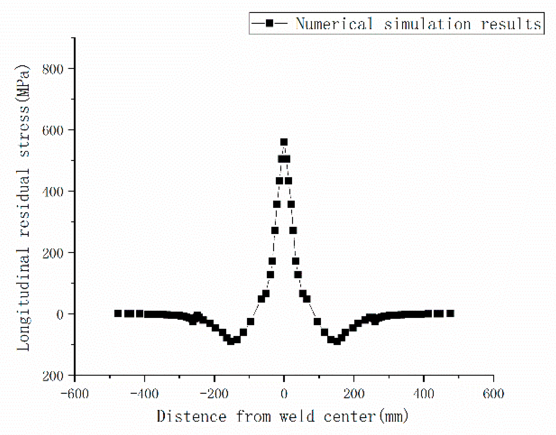
Both compressive and tensile stresses exist along the weld path on the outer surface of the hull comparing to total tensile stresses on the inner surface. The maximum tensile stress occurs on the inner surface approximates to 850 MPa, which is almost equivalent to the yield stress of the material.
(3)
Based on the analysis, the peak value of the residual stress does not satisfy the requirement of being less than 40% of the material yield stress in room temperature. In the viewpoint of manufacturing process flow for obtaining acceptable pressure hull, extra process measures should be taken into account, such as post-weld heat treatment. Numerical analysis on the basis of the present analysis results can provide reference for optimizing post-weld heat treatment parameters.

Author Contributions

Conceptualization, Fang Wang; methodology, F.W. and P.K.; software, P.K. and F.C.; validation, F.C. and Y.W. (Yu Wu); formal analysis, P.K. and Z.S.; investigation, J.Z.; resources, Y.W. (Yongmei Wang); data curation, J.Z.; writing—original draft preparation, F.W., P.K. and Z.S. writing—review and editing, Y.W. (Yongmei Wang); supervision, F.W.; project administration, F.W.; funding acquisition, F.W. All authors have read and agreed to the published version of the manuscript.

Funding

This work is supported by the National Natural Science Foundation of China (Grant No. 52071203 and No. 52101320) and National Key Research and Development Program of China (Grand No. 2021YFC2800600).

Data Availability Statement

Not applicable.

Acknowledgments

The authors would like to express their gratitude for the support of Fishery Engineering and Equipment Innovation Team of Shanghai High-level Local University.

Conflicts of Interest

The authors declare no conflict of interest.

References

  1. Cui, W.C.; Song, T.T. Manned submersible “Jiaolong” and its promotion role on the deep sea science and technology. Sci. Technol. Rev. 2019, 37, 108–116. [Google Scholar]
  2. Wang, F.; Hu, Y.; Cui, W.C. Preliminary Evaluation of Maraging Steels on Its Application to Full Ocean Depth Manned Cabin. J. Ship Mech. 2016, 20, 1557–1572. [Google Scholar]
  3. Pan, B.B.; Cui, W.C.; Shen, Y.S.; Liu, T. Further study on the ultimate strength analysis of spherical pressure hulls. Mar. Struct. 2010, 23, 444–461. [Google Scholar] [CrossRef]
  4. Pan, B.B.; Cui, W.C.; Shen, Y.S. Experimental verification of the new ultimate strength equation of spherical pressure hulls. Mar. Struct. 2012, 29, 169–176. [Google Scholar] [CrossRef]
  5. Wang, K.; Wang, F.; Cui, W.C. Prediction method of the dwell-fatigue crack growth for titanium alloys and its validation on Ti-6242 at room temperature. J. Ship Mech. 2013, 17, 1309–1317. [Google Scholar]
  6. Lu, B.; Liu, T.; Cui, W.C. Ultimate strength of pressure spherical hull in deep-sea manned submersible. J. Ship Mech. 2004, 8, 51–58. [Google Scholar]
  7. Yang, L.; Wang, F.; Zhang, X.Z.; Wang, M.Q.; Jiang, Z. Experimental and Numerical Simulation on Multi-Layer and Multi-Pass Welding of Titanium Alloy Ti-6Al-4V ELI Thick Plates. Ship Eng. 2021, 43, 122–127. [Google Scholar]
  8. Wang, Y.Y. Research on Fatigue Reliability of Manned Cabin of Full Ocean Depth Submersibles; China Ship Research Institute: Wuxi, China, 2017. [Google Scholar]
  9. Wang, F.; Yang, Q.S.; Hu, Y.; Cui, W.C. Study on Scaled Structure for Manned Cabin in Full Ocean Depth Submersible. Ship Build. China 2018, 59, 62–71. [Google Scholar]
  10. Pranesh, S.B.; Kumar, D.; Subramanian, V.A.; Sathianarayanan, D.; Ramadass, G.A. Non-linear buckling analysis of imperfect thin spherical pressure hull for manned submersible. J. Ocean Eng. Sci. 2017, 2, 293–300. [Google Scholar] [CrossRef]
  11. Shen, J.J.; Gonçalves, R.; Choi, Y.T.; Lopes, J.G.; Yang, J.; Schell, N.; Kim, H.S.; Oliveira, J.P. Microstructure and mechanical properties of gas metal arc welded CoCrFeMnNi joints using a 410 stainless steel filler metal. Mater. Sci. Eng. A 2022, 857, 144025. [Google Scholar] [CrossRef]
  12. Shen, J.J.; Gonçalves, R.; Choi, Y.T.; Lopes, J.G.; Yang, J.; Schell, N.; Kim, H.S.; Oliveira, J.P. Microstructure and mechanical properties of gas metal arc elded CoCrFeMnNi joints using a 308 stainless steel filler metal. Scr. Mater. 2023, 222, 115053. [Google Scholar] [CrossRef]
  13. Venkata, K.A.; Kumar, S.; Dey, H.C.; Smith, D.J.; Bouchard, P.J.; Truman, C.E. Study on the Effect of Post Weld Heat Treatment Parameters on the Relaxation of Welding Residual Stresses in Electron Beam Welded P91 Steel Plates. Procedia Eng. 2014, 86, 223–233. [Google Scholar] [CrossRef] [Green Version]
  14. Sha, Y.C. Effect of Heat Treatment on Welding Residual Stress of Titanium Alloy Pressure Spherical Shell; Jiangsu University of Science and Technology: Zhenjiang, China, 2020. [Google Scholar]
  15. Song, Q.J. Quality Control of Thick TC4ELI Titanium Alloy EBW and Spherical Shell Deformation Prediction; Harbin Institute of Technology: Harbin, China, 2015. [Google Scholar]
  16. Xia, X.W. Research on Electron Beam Welding Simulation and Welding Process for Port Stubs of Vacuum Vessel Sectors with Large Complex Contor; University of Science and Technology of China: Hefei, China, 2020. [Google Scholar]
  17. Li, L.B. Influence of residual stress due to the equatorial weld on the ultimate strength of a Ti80 spherical pressure shell. Int. J. Adv. Manuf. Technol. 2021, 116, 1831–1841. [Google Scholar] [CrossRef]
  18. Xu, L.; Huang, X.P.; Wang, F. Effect of welding residual stress on the ultimate strength of spherical pressure hull. J. Ship Mech. 2017, 21, 864–872. [Google Scholar]
  19. Zhang, J. Numerical simulation and experimental study on welding residual stress of pressure hull with external pressure method. J. Ship Mech. 2018, 22, 1007–7294. [Google Scholar]
  20. Liu, X.D. Research on numerical welding experiment of a thick spherical shell structure. J. Marine. Sci. Appl. 2008, 7, 69–76. [Google Scholar] [CrossRef]
  21. Yu, C.L. Influence of initial imperfections on ultimate strength of spherical shells. Int. J. Nav. Archit. Ocean. Eng. 2017, 9, 473–483. [Google Scholar] [CrossRef]
  22. Matos, C.G.; Dodds, R.H., Jr. Modeling the effects of residual stresses on defects in welds of steel frame connections. Eng. Struct. 2000, 22, 1103–1120. [Google Scholar] [CrossRef]
  23. Shen, J.J.; Agrawal, P.; Rodrigues, T.A.; Lopes, J.G.; Schell, N.; Zeng, Z.; Mishra, R.S.; Oliveira, J.P. Gas tungsten arc welding of as-cast AlCoCrFeNi2.1 eutectic high entropy alloy. Mater. Des. 2022, 223, 111176. [Google Scholar] [CrossRef]
Figure 1. Manned cabin of 10,000 m-class submersible made in China: (a) actual photograph, (b) structure of the spherical pressure hull of the manned cabin with outside frame for heat treatment, and (c) distribution of welding on spherical pressure hull of the manned cabin.
Metals 12 01958 g001
Figure 2. Electron beam welding of 32 mm-thick Ti-6Al-4V plate.
Metals 12 01958 g002
Figure 3. Measured data of longitudinal residual stress along vertical weld path.
Metals 12 01958 g003
Figure 4. Residual stress simulation flowchart.
Metals 12 01958 g004
Figure 5. Conical heat source model.
Metals 12 01958 g005
Figure 6. Meshing of the finite element model.
Metals 12 01958 g006
Figure 7. Shape of the weld pool compared to the experimental result.
Metals 12 01958 g007
Figure 8. Temperature field distributions (a) on the weld surface when t = 6 s, (b) in the direction perpendicular to the weld when t = 6 s, and (c) on the weld surface when t = 10 s.
Metals 12 01958 g008
Figure 9. Thermal cycle curve of typical node on the path vertical to the weld.
Metals 12 01958 g009
Figure 10. Comparison between simulation and test results of longitudinal residual stress along vertical weld path.
Metals 12 01958 g010
Figure 11. Meshing of the spherical pressure hull model.
Metals 12 01958 g011
Figure 12. Coordinate system for equator welding simulation.
Metals 12 01958 g012
Figure 13. Trajectory of heat source centre.
Metals 12 01958 g013
Figure 14. Conversion of coordinate systems.
Metals 12 01958 g014
Figure 15. Temperature fields of (a) weld section when t = 4 s, (b) weld section when t = 12 s, (c) spherical pressure hull when t = 4 s, and (d) spherical pressure hull when t = 12 s.
Metals 12 01958 g015
Figure 16. Enlarged temperature field of the spherical pressure hull when t = 12 s.
Metals 12 01958 g016
Figure 17. Longitudinal residual stress along the vertical weld path on the outer surface of the spherical pressure hull.
Metals 12 01958 g017
Figure 18. Transverse residual stress along the vertical weld path on the outer surface of the spherical pressure hull.
Metals 12 01958 g018
Figure 19. Residual stress along the weld on the outer surface of the spherical pressure hull.
Metals 12 01958 g019
Figure 20. Longitudinal residual stress along the vertical weld path on the inner surface of the spherical pressure hull.
Metals 12 01958 g020
Figure 21. Transverse residual stress along the vertical weld path on the inner surface of the spherical pressure hull.
Metals 12 01958 g021
Figure 22. Residual stress along the weld on inner surface of the spherical pressure hull.
Metals 12 01958 g022
Table 1. Thermophysical performance parameters of Ti-6Al-4V.
Temperature T (°C)Poisson’s RatioSpecific Heat C (J/kg °C)Elastic Modulus E (MPa) × 105Thermal Conductivity λ (W/(m °C))Yield Stress σ (MPa) × 105Thermal Expansion Coefficient K (1/°C) × 10−6
200.346111.125.448957.60
1000.346421.107.10-7.89
2000.346501.048.79-9.01
3000.356740.9810.47-9.30
4000.376910.9212.565909.24
5000.377080.8614.244409.39
6000.397270.8215.91-9.40
Publisher’s Note: MDPI stays neutral with regard to jurisdictional claims in published maps and institutional affiliations.

