1. Introduction
Metal alloys obtained using additive manufacturing are getting wider adoption to-day. Such materials may have higher strength, hardness, and wear resistance as com-pared to materials obtained by conventional alloying [
1]. Currently, about 30 metals and alloys are produced in the form of powders, including stainless and tool steels, aluminum alloys, and high-temperature steels [
2]. Products made from additive manufactured materials are widely used in the aero-space industry, for example, in production of turbine engine blades. Alloys used for manufacturing turbo engine parts must have high strength, high impact strength, high heat strength, and high corrosion resistance [
3]. For manufacturing turbine blades, nickel-based alloys are used including the following grades as an example: KhN35VTYu, KhN55VMTKYu, KhN62MVKYuL, KhN67MVTYuL, KhN70MVTYuB, KhN75VMYu, KhN80TBYu, ZhS6UD [
4]. However, as of today, the characteristics of these alloys do not always meet the requirements put forward to them. There is a need to research and develop new powder materials with improved physical and mechanical properties relative to traditional alloys. It is known that obtaining new physical and mechanical properties of materials is achieved by changing their structures in a certain way. One of the ways to change the structure of materials, which makes it possible to increase their physical and mechanical properties, is the addition of ceramic particles to metal powder in the process of additive growth [
5,
6,
7]. However, this method reduces the wettability of ceramic inclusions, which leads to their agglomeration and the creation of an inhomogeneous structure, as well as a decrease in the density of the samples and the formation of a large number of pores. In [
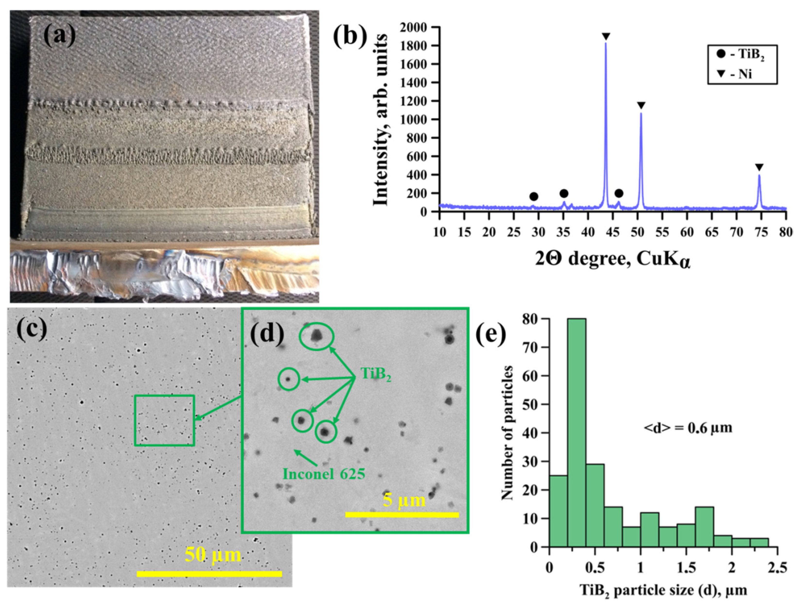
8], experimental studies were carried out on the synthesis of powders of composite metal matrix materials (Ni-Ti)-TiB2 by the method of self-propagating high-temperature synthesis. The authors of the work found that the particles of composite powders consist of an intermetallic Ni-Ti matrix and ceramic inclusions of titanium diboride (TiB2). The size of ceramic inclusions varies from 0.1 to 4 µm, and their average size is 0.57 µm. The obtained composite SHS powders (Ni-Ti)-TiB2 were used as an additive to Inconel 625 powder in the process of additive laser growth [
9]. It has been established that in the process of additive growth, the intermetallic matrix of (Ni-Ti)-TiB2 SHS particles melts under the action of a laser beam. The matrix melt wets the titanium diboride ceramic inclusions and thus prevents their agglomeration and recrystallization. The structure of composites obtained by additive growth inherits the structure of (Ni-Ti)-TiB2 composite SHS powders and consists of an Inconel 625 matrix and titanium diboride ceramic inclusions. In [
10], the authors found that the addition of 5-10 wt.%. composite SHS particles in the initial powder mixture: Inconel 625—(Ni-Ti)-TiB2 allows to achieve the most optimal improvement in the mechanical properties of materials obtained by additive laser growth, relative to materials from pure Inconel 625 (
Table 1).
One of the main requirements in the production of materials by the method of additive laser growth is the high accuracy of their dimensions and shape, which is achieved by additional mechanical processing of these materials. The main problem lies in the lack of recommendations on the choice of cutting regimes for milling composite metal-matrix materials Inconel 625-TiB2 obtained by additive laser growth. The present paper studies milling machinability of a composite Inconel 625-TiB2 fabricated by direct laser deposition in order to determine optimal regimes for its milling.
Machinability is understood as ease with which metals can be machined. According to [
11], the main indicators for evaluating machinability are such parameters as cutting forces, surface layer quality, tool wear, heat released during the deformation of the material of the layer being cut, the presence or absence of a tendency for build-up formation, as well as type, shape, and size of shavings. Depending on these characteristics, all materials are subdivided into eight groups [
4].
Taking into account the chemical composition of the material under study and in accordance with recommendations from [
4], the Inconel 625-TiB
2 composite with added should be assigned to machinability group V–VI. These groups include high-temperature, heat-resistant, and acid-resistant steels, as well as nickel and iron-nickel alloys. These groups have very low machinability with a coefficient of 0.16–0.08 as compared to steel grade 45, for which this coefficient equals 1. Low machinability is associated with high tensile strength and hardness, which strongly affect cutting forces during machining. Cutting forces exerted in the course of machining of sintered alloys can be greater than those exerted when cutting similar alloys are obtained by conventional methods [
12]. This is most likely due to higher strength characteristics of alloys fabricated by laser sintering.
Another peculiarity of the composite under study is that it contains titanium diboride (TiB2) that has high hardness and negative effect on cutting tool durability. There are no recommendations on the choice of cutting regimes for metal matrix composites obtained by additive techniques from powders with added ceramics.
Moreover, due to low thermal conductivity of such alloys, the heat produced during machining is transferred more into the tool rather than into the workpiece, causing excessive heating of the cutting edge and resulting in tool wear [
3].
In the process of milling hard-to-cut materials, the processing speed and feed rate have the greatest impact on tool life, surface roughness, and cutting forces [
13]. According to [
14], when milling high-temperature nickel alloys, it is recommended to use tools made of hard alloys for machining at low cutting rates (15–20 m/min) and a feed of 0.02 mm/tooth. However, when milling high-temperature alloys, more aggressive cutting regimes and hard-alloy tools with wear-resistant coating are recommended in the literature [
15,
16]. Specifically, machining should be carried out by climb milling at a cutting rate of 20 to 50 m/min and feeds of 0.10–0.15 mm/tooth. Moreover, in [
17] it is reported that ceramic tools exhibit better resilience when machining certain high temperature alloys (such as Inconel 718), but such tools are much more expensive.
To improve the machinability of heat-resistant materials, ultrasonic vibrations are applied to a tool or a workpiece, thereby reducing cutting forces required as well as tool temperature and wear. The work [
18] discusses the possibility of processing nickel-based materials on ULTRASONIC machines by DMG MORI. However, an analysis of the literature has shown that this technology is mainly used for processing brittle materials, glass, and carbon fiber [
19,
20].
It should be noted that in the literature on the choice of cutting regimes, it is easier to find information about choosing cutting speeds and feed rates, while there are almost no recommendations on the choice of milling depth and width. In [
21,
22,
23], the high efficiency milling (HEM) method was described. This method was designed for roughing metals using shallow milling depth (
Ae) and broad milling width (
Ap). When a high
Ae and a small
Ap are used in milling, the heat is concentrated in a small part of the cutting tool thus accelerating its wear. Using the full length of the cutter’s cutting edge allows wear to be spread over a larger area, which extends tool life and dissipates the heat while reducing cutter breakdown probability. The HEM method involves the use of 7–30% of the cutter diameter in the radial direction and twice the cutter diameter in the axial direction, in combination with an increased feed rate [
21].
Thus, the machinability of this nickel-based composite with added ceramics has not been studied yet, which underpins the relevancy of the present work.
The main objectives of this work are:
Determine the process feasibility of machining an Inconel 625-TiB2 composite using end mill cutters.
Determine the recommended rake angle for minimum wear and minimum cutting forces exerted during machining.
Determine the cutting speed for minimum tool wear and minimum cutting forces.
Determine optimal feed per tooth for machining the material with minimum tool wear and minimum cutting forces exerted.
Determine optimal ratio of milling depth vs. width for minimal tool wear and minimal cutting forces.
2. Materials and Methods
Composite metal matrix samples were fabricated by additive laser growth from an Inconel 625 + 5 wt.% NiTi-TiB2 powder mixture using an LS-3 fiber laser (IPG Photonics). The technique of additive laser growth is presented in [
9]. The parameters of laser exposure are shown in
Table 2.
The appearance, phase composition, and structure of composite materials obtained by direct laser growth from a powder mixture of Inconel 625 + 5 wt.% NiTi-TiB2 are shown in
Figure 1. The physical and mechanical properties of these composites, obtained by the method [
9,
10] are presented in
Table 3.
All the machining was done on a VF1 CNC vertical mill by Haas (Oxnard, California, USA). Climb milling approach was chosen for the workpieces.
As a cutting tool in the study, solid-carbide milling cutters were used. Four-tooth cutters with a diameter of 8–10 mm were used in the work. All cutters are made from H10F grade. All cutters were coated with TiAlN. This coating is recommended by cutting tool manufacturers for cutting materials with low thermal conductivity, such as stainless steels, titanium, and nickel alloys. To determine optimal cutting geometry suitable for milling the Inconel 625-based composite, the effect of different rake angles of cutters on the machining process was investigated.
Solid-carbide Ø8 mm end mill cutters were used as cutting tools. The main geometric parameters of the cutters are presented in
Table 4.
Based on the recommendations on the machining regimes of high-temperature alloys and the analysis of the literature [
4,
14,
16], the feed per tooth of 0.04 mm/tooth and the cutting speed of 30 m/min were chosen for the experiments. The cutters were fixed in a collet chuck with identical overhang, 24 ± 0.5 mm. Moreover, for a qualitative and quantitative assessment of the experimental results, the wear of cutters and the cutting forces were measured.
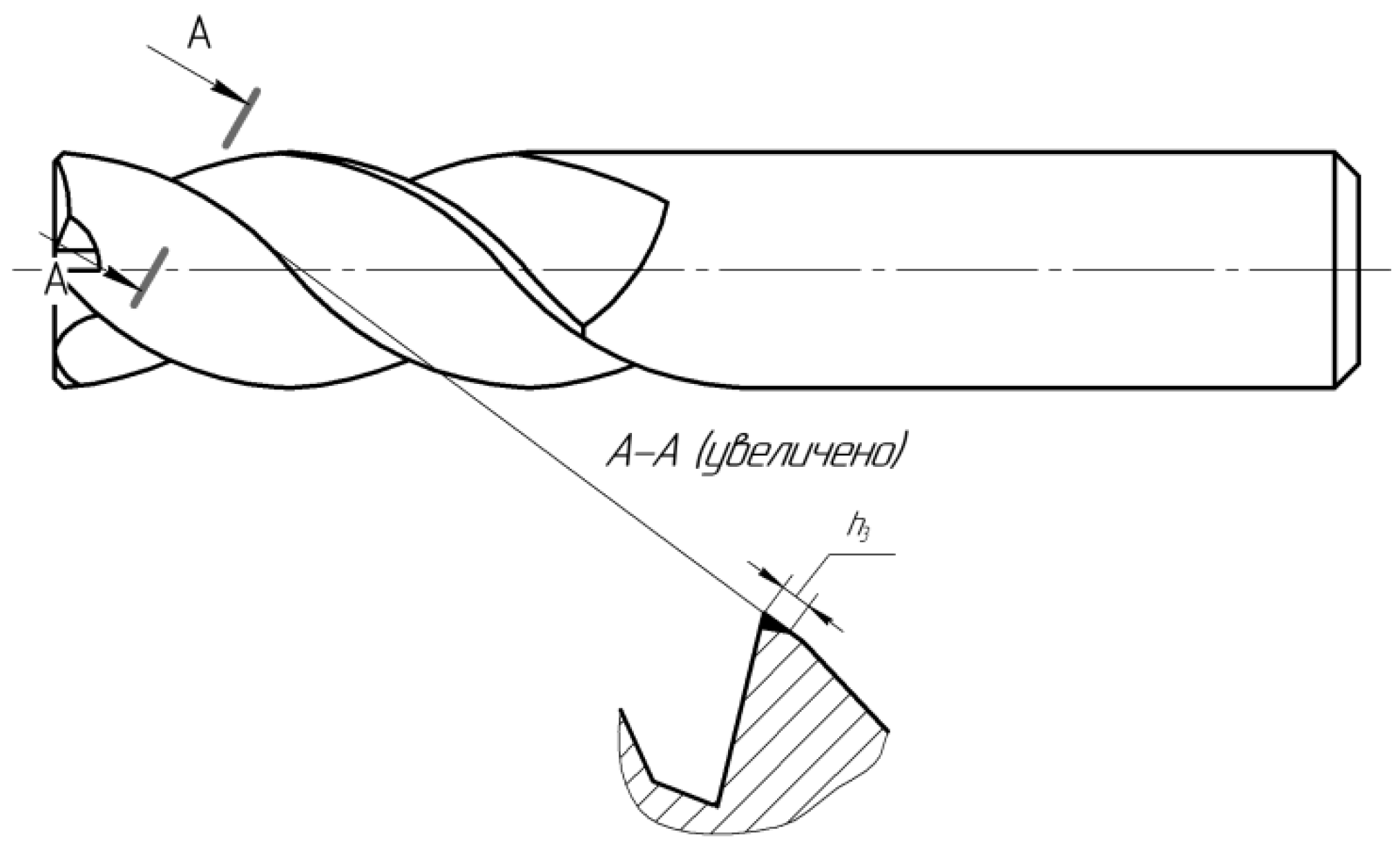
In our study, the value of wear along the rear surface of the cutter was chosen as the wear criterion. With an increase in this parameter, there was a sharp increase in cutting forces and an increase in wear, accompanied by chipping of the cutting edge. The wear chamfer along the back surface was measured in the plane normal to the helical cutting edge of the tooth, this parameter was designated by the letter hz (
Figure 2). The width of the wear chamfer was measured with an optical microscope. The average wear value for four teeth was calculated. It should be noted that before the critical value, the wear mark on the back surface was quite clear, the scatter of the measured values of the wear chamfer did not exceed 7% of the average wear value, which indicates the reliability of the experimental data.
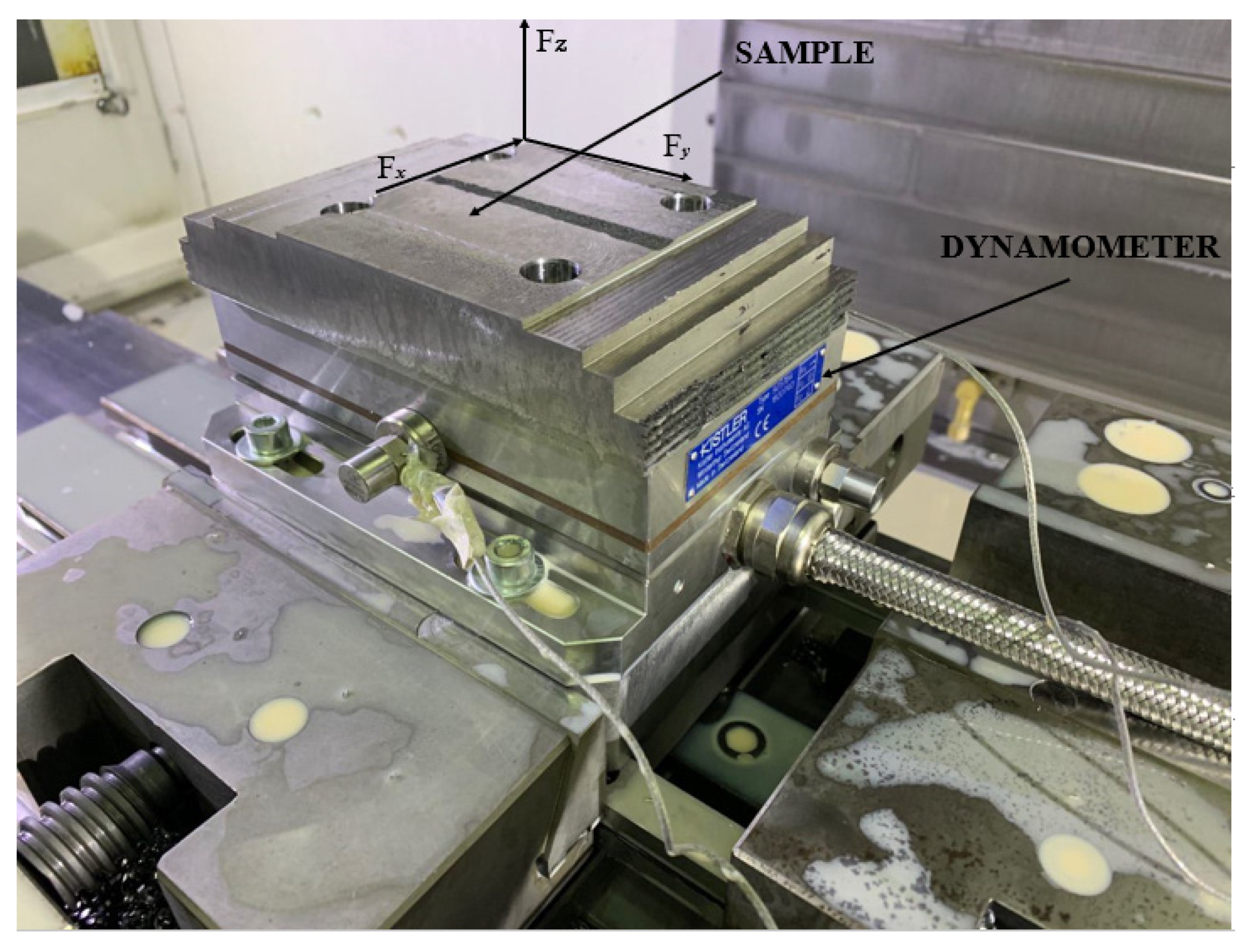
The cutting forces were determined using a Kistler 9257B dynamometer (Switzerland). The measurements were carried out in three mutually perpendicular directions (
Figure 1). To evaluate the results, we used the total force
acting in the plane perpendicular to the axis of the cutter. The dynamometer was mounted on a special plate and it was fixed in a vice on the milling machine. Before starting the experiments, mounting holes were drilled in the workpiece, and through these holes the workpiece was fixed on the dynamometer with four screws (
Figure 3).
To solve the problem of choosing the cutting speed, the machining was performed at three cutting speeds: V1 = 25 m/min; V2 = 35 m/min; and V3 = 50 m/min. For milling Inconel 625, cutting speeds of 45–60 m/min are used. Our material due to the addition of NiTi-TiB2 reduces the wear resistance of the tool, so the speed was reduced. Meanwhile, feed per tooth as well as milling depth and width remained constant: Sz = 0.04 mm/tooth; Ap = 4 mm; Ae = 1 mm. Cutter wear was measured at regular intervals.
In the course of research aimed to determine the effect of different feeds per tooth on the machining process, ZhT641 Ø10 mm milling cutters with a rake angle of γ = 4° were used. These cutters exhibited the highest resistance in the previous experiment. The cutting speed and depth-to-width ratio remained constant and were
V = 30 m/min and
Ae =
Ap/16, respectively. The feed rates under study are presented in
Table 5.
Quantitative and qualitative evaluation of the results was also carried out by measuring the wear of cutters and the cutting forces during the machining.
To determine the optimal ratio of depth and width of milling for maximum cutter life, three options of
Ae to
Ap ratio (
Ae =
Ap;
Ae =
Ap/4;
Ae =
Ap/16) were chosen, while the volume of the cut layer per unit of time, i.e., the product
Ae1 ×
Ap1 =
Ae2 ×
Ap2 =
Ae3 ×
Ap3 for all three variants of the selected modes, had to remain constant and provide for identical machining performance. The cutting speed was 25 m/min, and the feed rate was
Sz = 0.04 mm/tooth. The cutting patterns are provided in
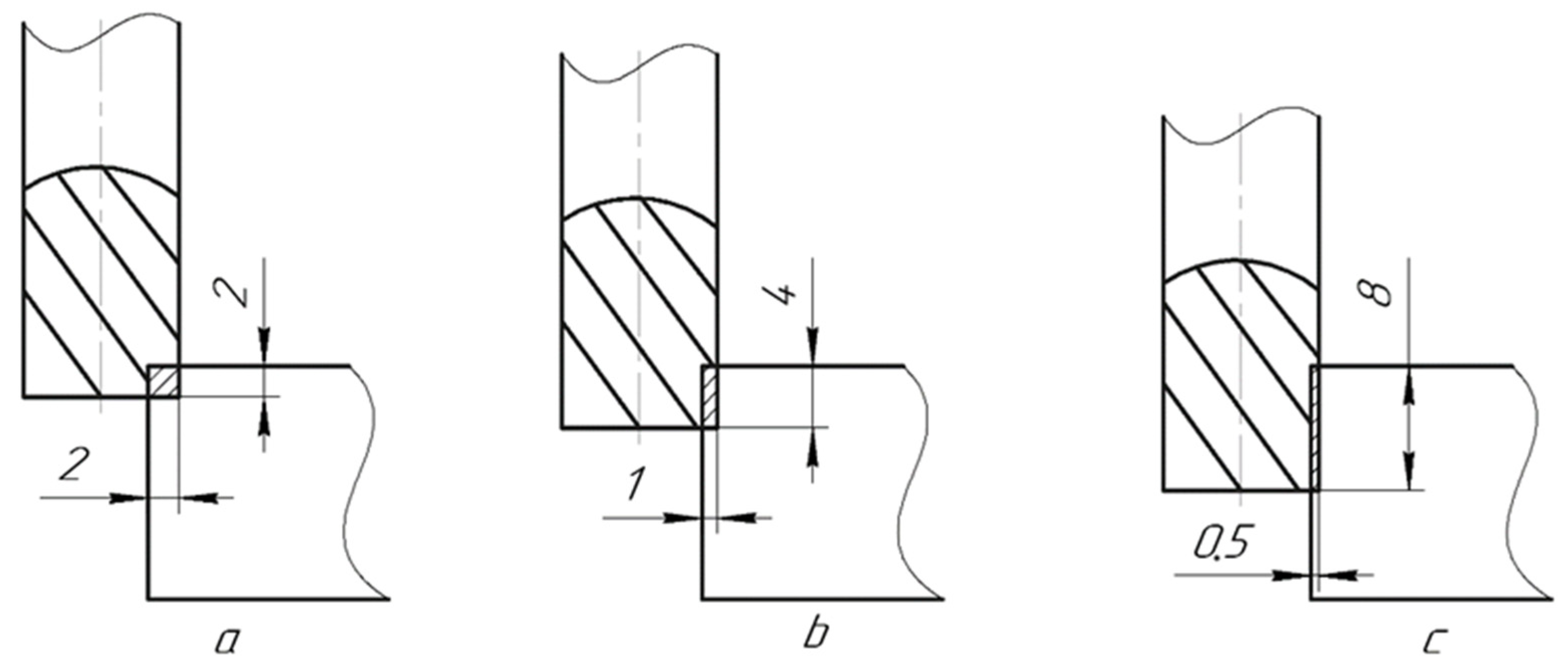
Figure 4.
Thus, for cutter No. 1, the milling depth and width were
Ae = 2 mm and
Ap = 2 mm, respectively. For cutter No. 2, the milling depth was
Ae = 1 mm, therefore, the width was increased to
Ap = 4 mm. For cutter No. 3 at
Ae = 0.5 mm, the width was
Ap = 8 mm (
Figure 2).
For data collection and analysis, DynoWare software (by Kistler, Winterthur, Switzerland) was used. All the received data were processed in Microsoft Excel.
3. Results and Discussion
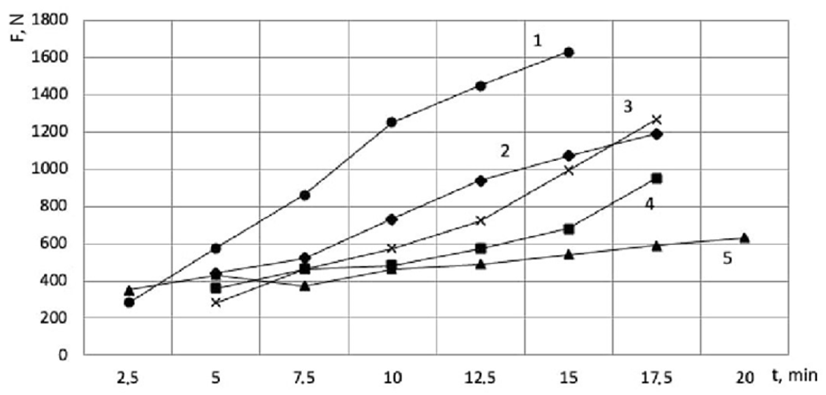
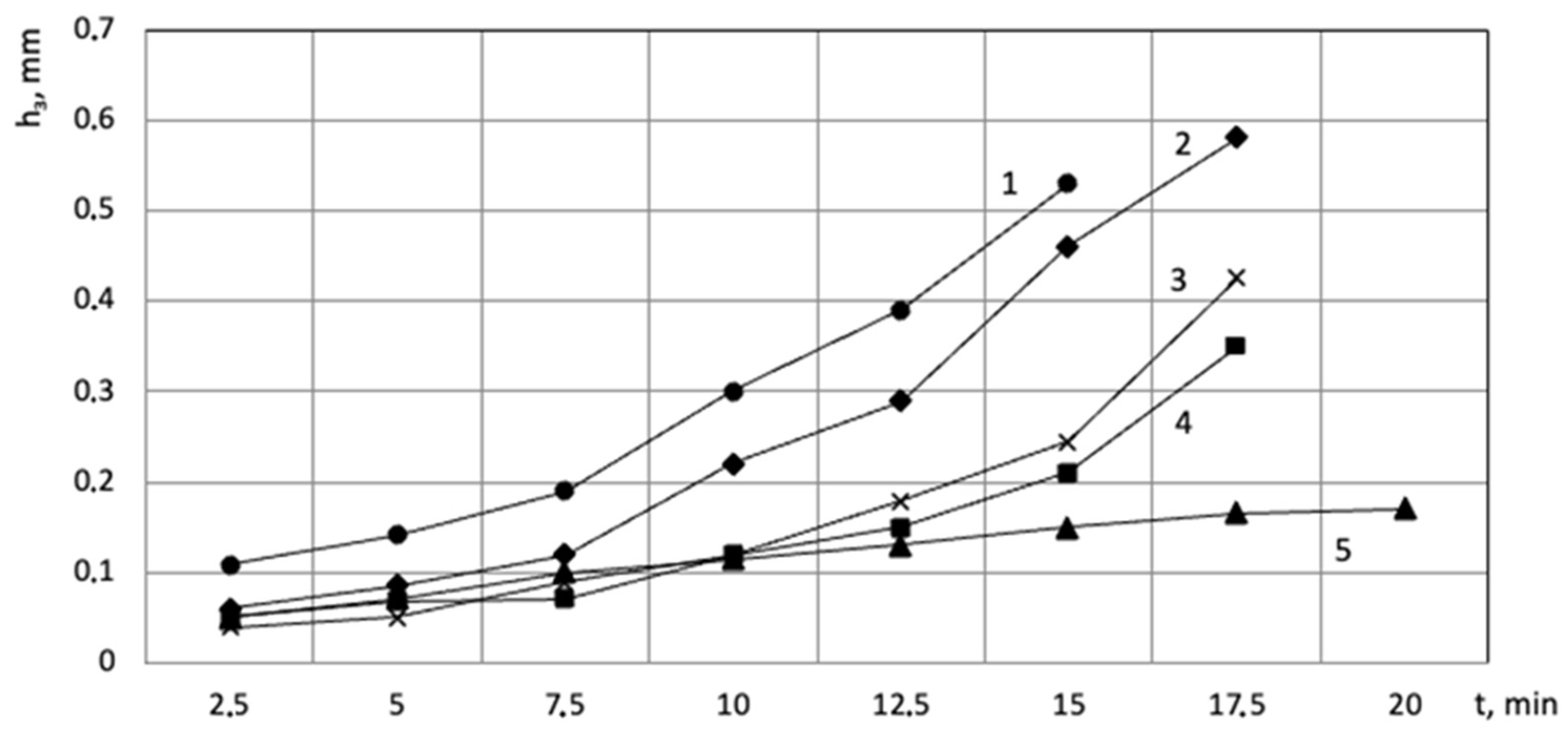
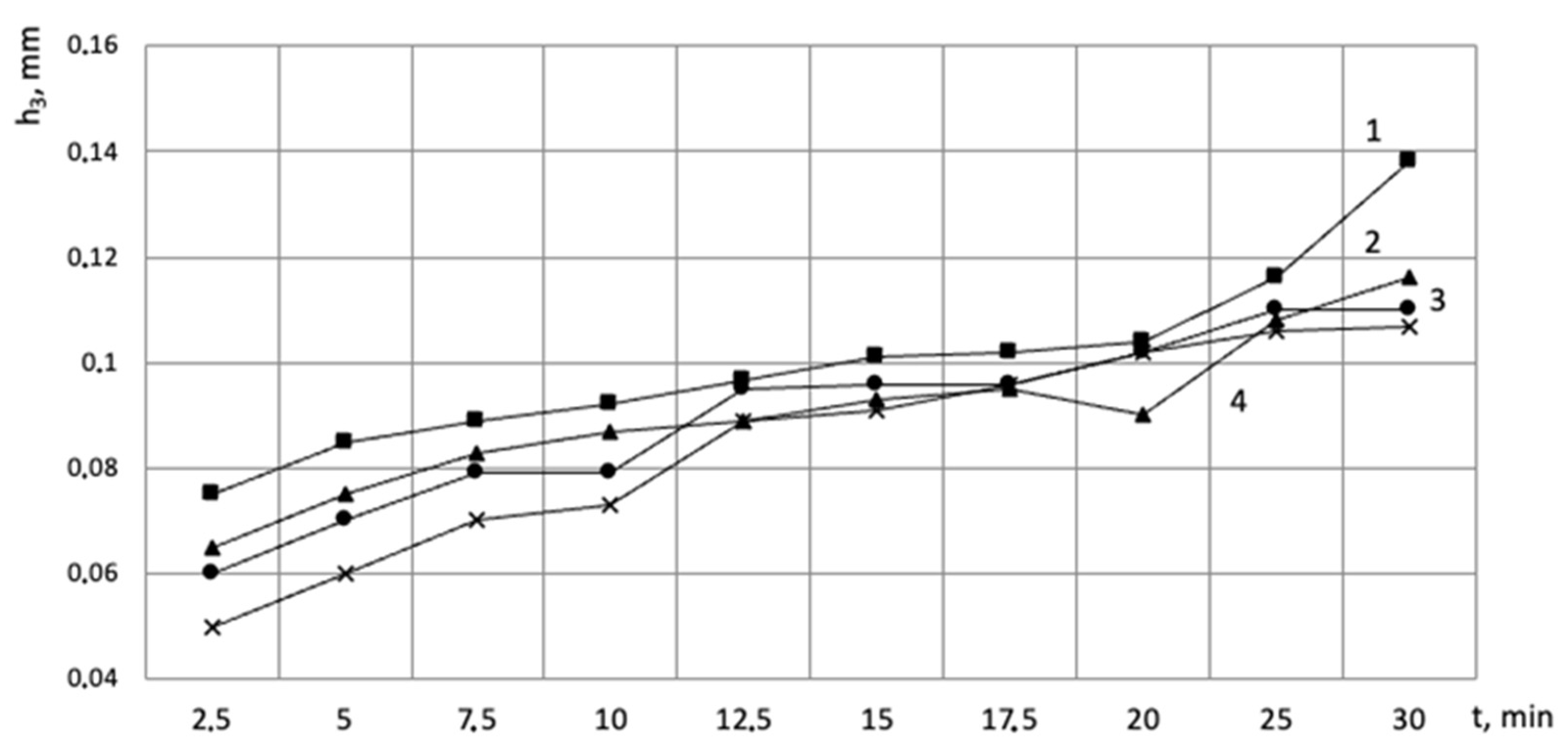
Figure 5 shows a graph representing the amount of flank wear land of the tooth vs. the operating time of the cutter for cutters with different rake angles. It can be seen from the graph that the cutter with a rake angle of 12° sustained the greatest wear: after 7.5 min of operation catastrophic wear began, and after 15 min of operation, the wear exceeded 0.5 mm. Similar wear values were exhibited by a cutter with a negative angle (−7°): by the 10th minute of operation, the wear reached 0.2 mm. The three remaining cutters at the beginning of operation had almost the same wear, and by the 10th minute of operation, the wear reached 0.1 mm. Then cutters with rake angles of 0° and 8° reached a value of 0.2 mm on the 15th minute. The cutter with a rake angle of 4° sustained the least wear in the investigated period of time, so the wear was 0.17 mm on the 20th min. The obtained values are also confirmed by the graphs of the cutting forces in
Figure 6.
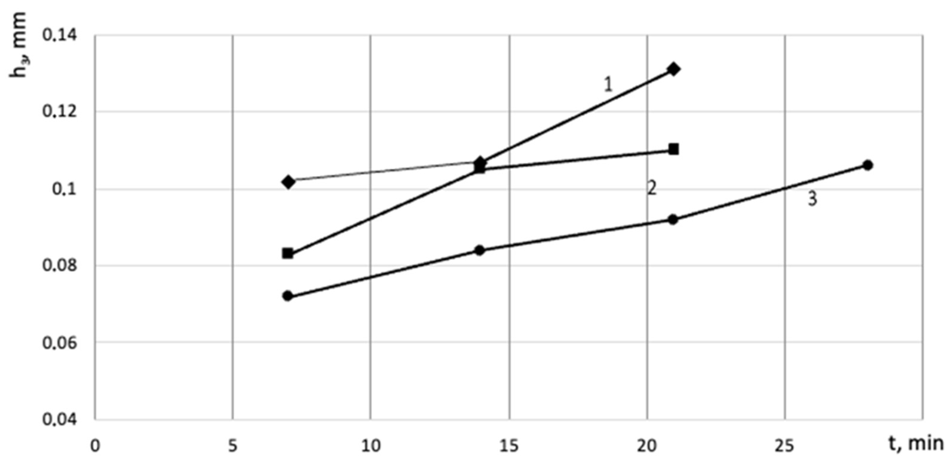
Figure 7 shows the graph of the flank wear land of the tooth vs. the time of operation of the cutter for the cutting speeds of 50, 35, and 25 m/min (curves 1, 2, and 3, respectively). It can be seen from the graph that the cutter operating at the cutting speed of 25 m/min sustained the least wear in the investigated period of time, so on the 28th min of operation, the flank wear land reached 0.11 mm. The cutter operating at the speed of
V = 50 m/min had the highest wear, so the wear value reached 0.11 mm as early as on the 14th minute.
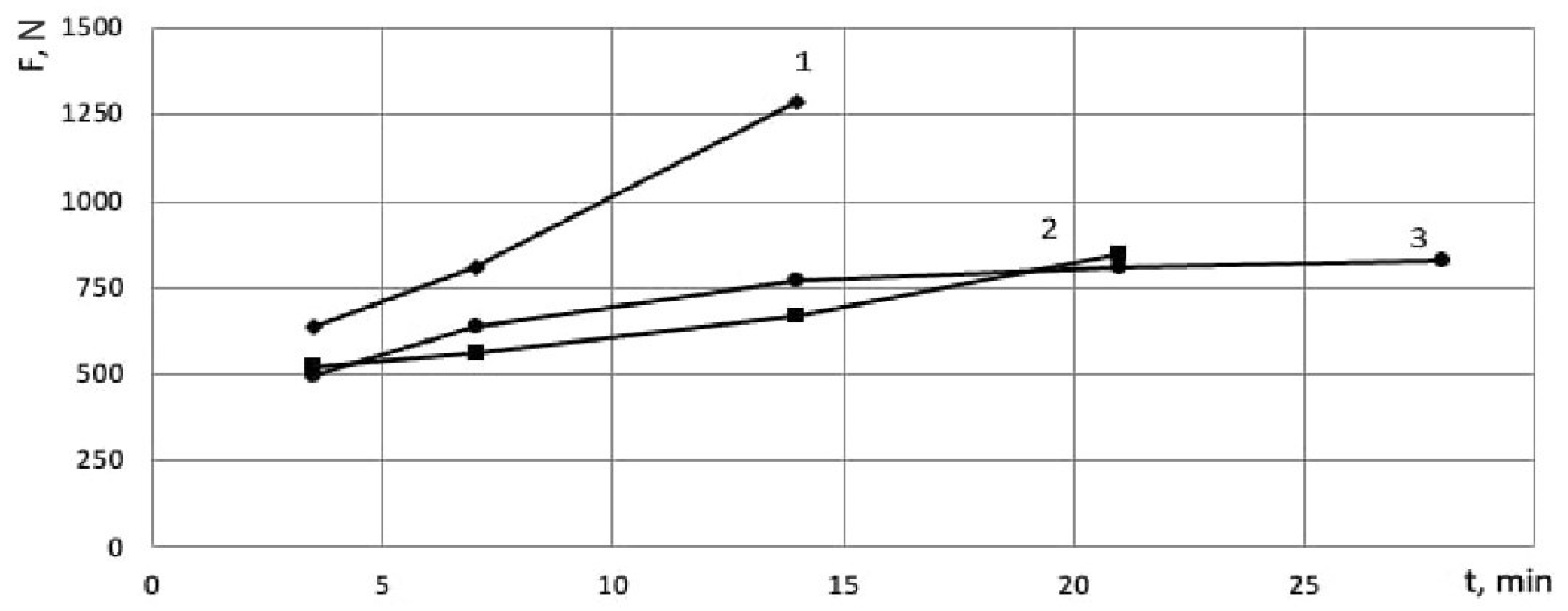
It is obvious that the increase in the forces in the investigated period of time is caused by the wear of cutters (
Figure 8). The cutter operating at the speed of
V = 50 m/min (
Figure 8, curve 1) demonstrates the most intensive increase in the forces over the entire range under study. For the cutters operating at the speeds of 35 and 25 m/min, the increase in the cutting forces over time also correlates with the amount of wear, but is less intense than when cutting at the speed of 50 m/min.
In the next part of the research, the effect of feed per tooth on tool wear was investigated. It can be seen from the graph in
Figure 9 that the cutter operating at the feed rate of
Sz = 0.06 mm/tooth had the highest wear. After 30 min of operation, the wear reached 0.14 mm.
According to the results of the work performed, it can be concluded that a change in feed per tooth does not significantly affect the flank wear land. The feed range from 0.03 to 0.05 mm/tooth at the cutting speeds of 25–35 m/min is optimal for milling this composite.
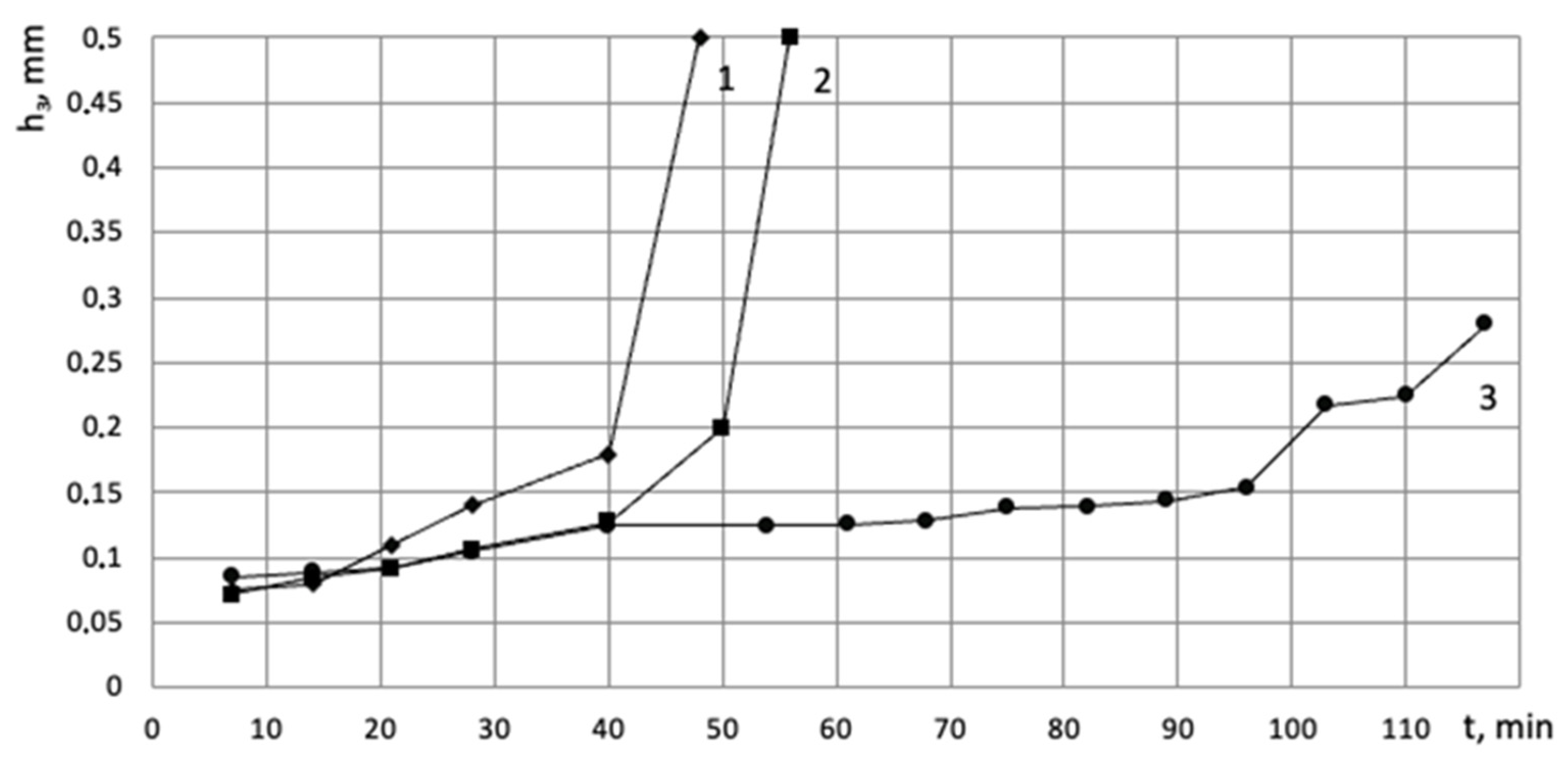
Figure 10 shows the dependencies of wear, and
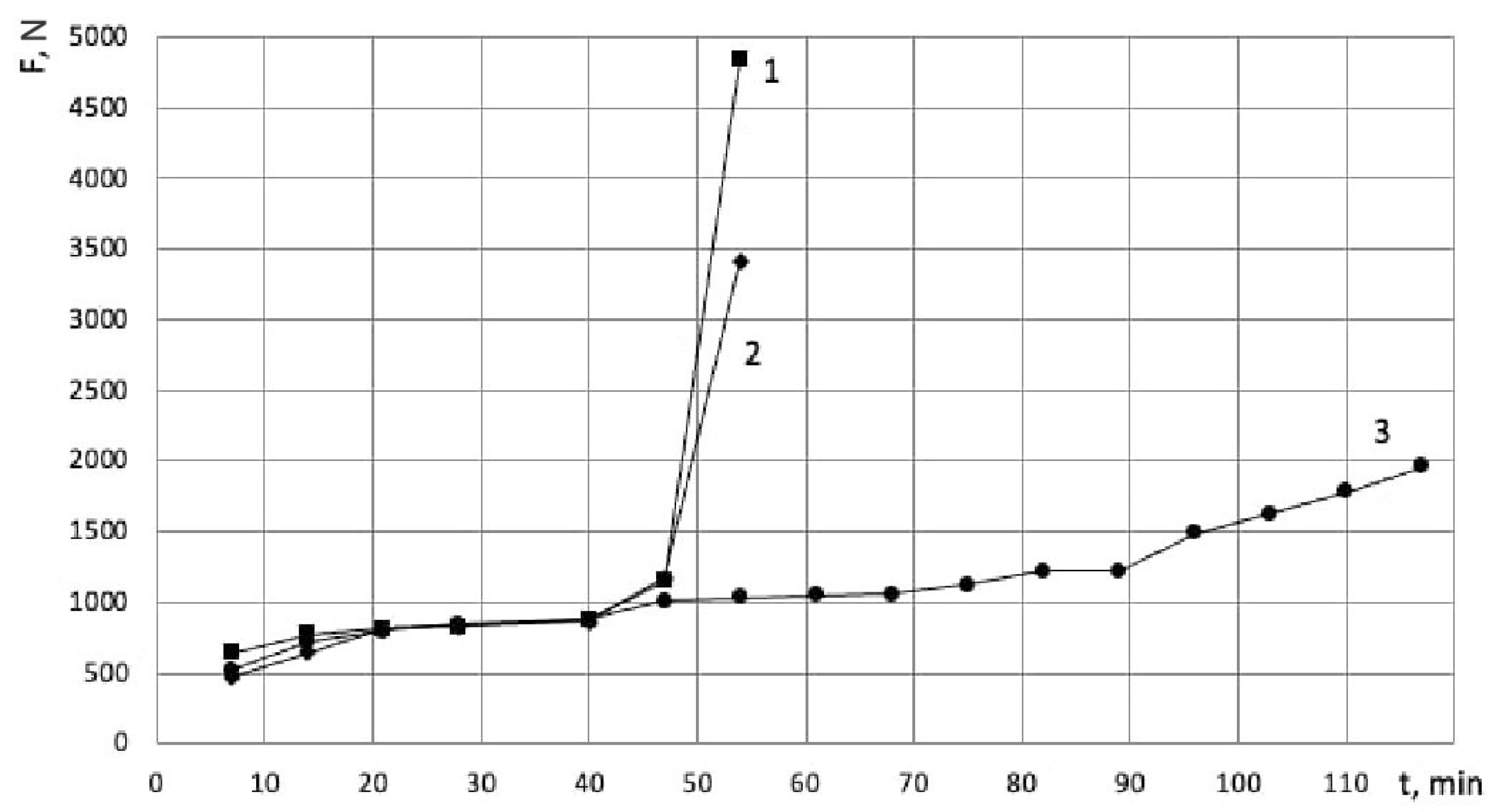
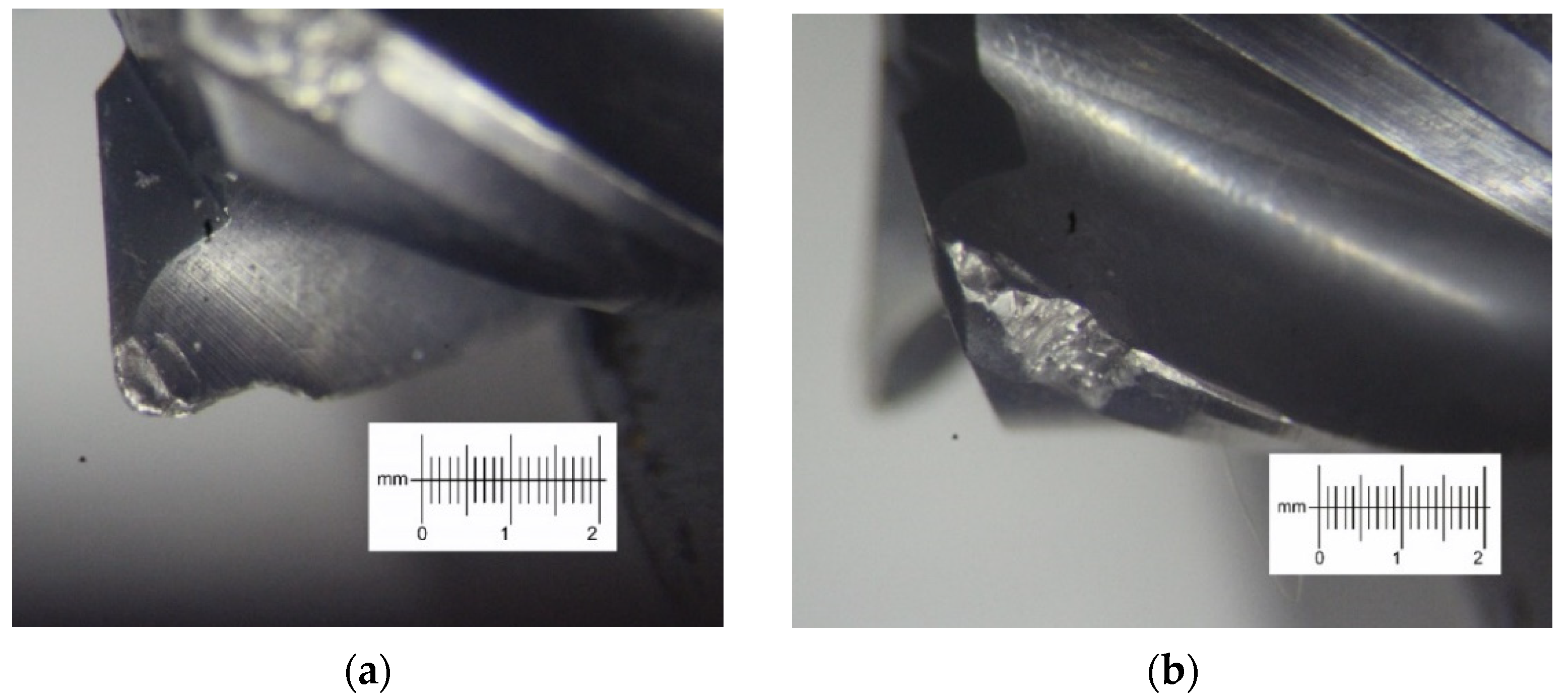
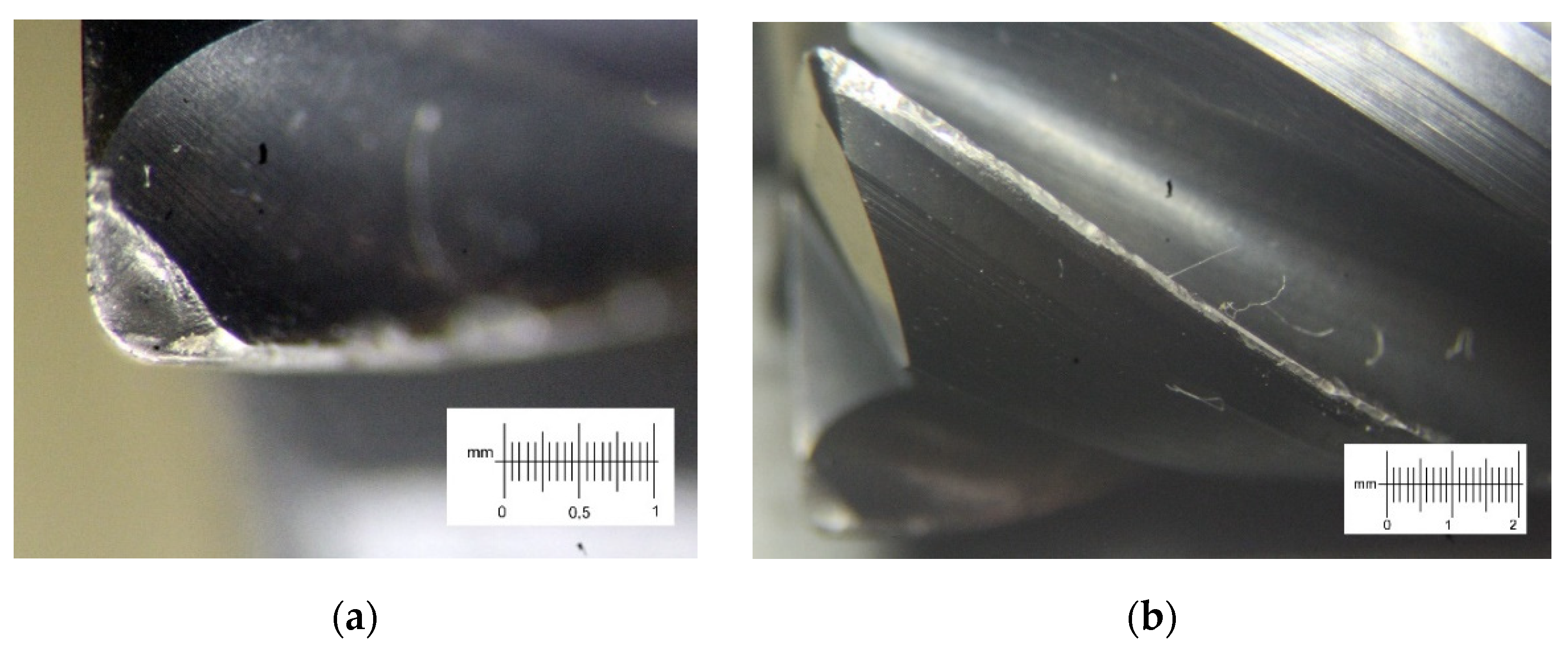
Figure 10 shows the dependencies of the cutting forces on the operating time for various ratios of milling depth vs. milling width. After 40 min of milling, critical wear of cutters No. 1 and No. 2 occurs with chippings of the cutting edge. Cutter No. 3 working at the ratio of 1:16 lasted 117 min, which is significantly longer than the others, and it did not undergo catastrophic wear with edge destruction. A sharp increase in the wear intensity of the flank wear land of cutter No. 3 occurred on the 92nd min only, and this was after the flank wear land value exceeded 0.15 mm, while cutters No. 1 and No. 2 reached this value on the 32nd and 43rd min, respectively. The maximum width of the flank wear land of the third cutter after 117 min of operation was 0.28 mm. From the forces graph (
Figure 11) it can be seen that the forces had very close values in the cutters operating time interval from 0 to 40 min for different ratios of milling depth vs. milling width. This can be explained by the same volume of the layer cut per a unit of time, but as soon as the wear surpasses the critical value (between 0.11 and 0.15 mm), then there is an instant increase in the forces. Therefore, before critical wear, the ratio of milling width vs. milling depth does not influence the cutting forces, and the change in the forces for different ratios of
Ae to
Ap (with the same volume of the cut layer per unit of time, i.e.,
Ae × Ap = constant if S = constant) is explained only by differing cutter wear, which is fully confirmed by
Figure 9 and
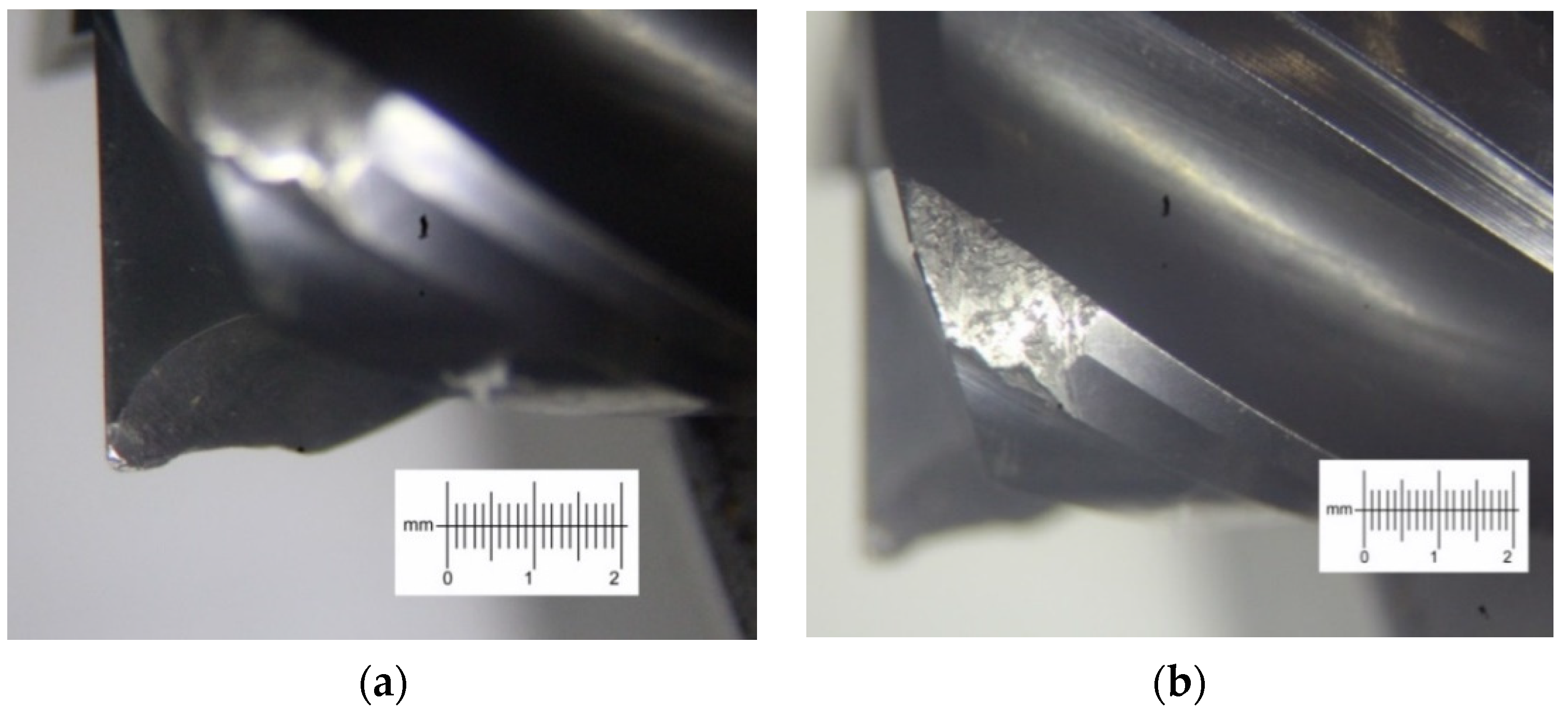
Figure 10. In the course of research, it was found that the wear prevails along the cutter tooth flank. Moreover, it should be noted that uneven wear is mainly caused by mechanical abrasion (
Figure 12,
Figure 13 and
Figure 14).
From the analysis of the graphs of established dependencies and photographs of cutter wear, it can be concluded that the machining pattern of cutter No. 3 with a depth-to-width ratio of 1:16 is the most efficient one. It is assumed that this is due to the lower bending moment applied to the cutter during operation and more uniform distribution of cutting temperature along the cutting edge.
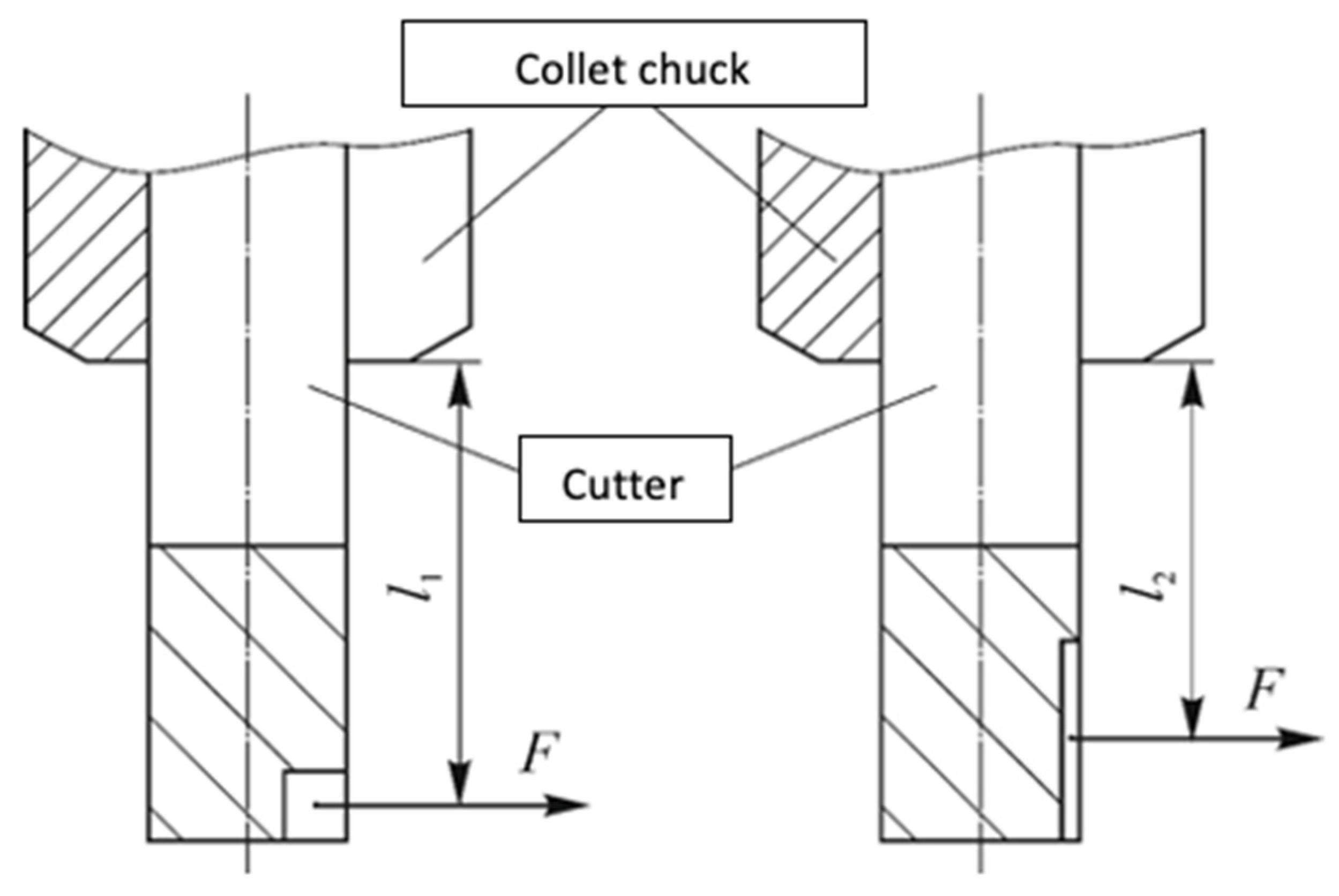
It can be seen from the force graphs that for different
Ae to
Ap ratios with the same volume of the cut layer, the values of the cutting forces before the onset of critical wear are approximately the same. However, if the load distributed along the cutting edge is replaced by a point force, the point of application of this force will be different, as shown in
Figure 15.
It can be seen from the diagram that for the ratio of depth and width of 1:1, the arm of the point force
is greater than the arm
for the ratio of 1:16. Therefore, the bending moment applied to the first cutter is greater. For cutter No. 1, the bending moment is M1 = 2.75 Nm, and for cutter No. 3, M3 = 2.26 Nm. To calculate the bending moment, the value of the force was obtained from the experiment, and the arm of the acting force was determined in accordance with the diagram shown in
Figure 11. The bending moment of the first cutter is almost 20% greater than that of the third. This leads to a greater amplitude of oscillations and vibrations of the cutter, which increases its wear, and after reaching the critical wear value, the force increases sharply and then the difference in the bending moments becomes even greater.
Another reason for excessive wear may be the nature of the temperature distribution in the cutting zone. Thus, for example, for a small width and a large depth of milling, the temperature during the cutting process is localized in a small area of the tool [
21], which accelerates the wear process. As the milling width is increased, the temperature is distributed over a greater length of the cutting edge of the cutter, reducing the wear rate.

 ,
, 


