Article

Simulation Analysis and Experimental Study on SLM Forming Titanium Alloy Milling Hole

School of Artificial Intelligence, Beijing Technology and Business University, Beijing 100048, China
*
Author to whom correspondence should be addressed.
Metals 2022, 12(11), 1919; https://doi.org/10.3390/met12111919
Submission received: 5 October 2022 / Revised: 2 November 2022 / Accepted: 7 November 2022 / Published: 9 November 2022
(This article belongs to the Special Issue Advanced Metal Cutting Technology and Tools)

Abstract

:
Using finite element analysis software and based on the Johnson–Cook failure criterion, a 3D printing workspace model with collapse, powder sticking, and cavity defects was established under the selective laser melting (SLM) forming process. The simulation analysis of milling holes was carried out, and the relationship between cutting speed and material-removal rate on tool wear and entrance burr was derived. The hole-milling experiment was carried out to verify the dimensional accuracy and surface appearance of the hole under the two processes of SLM direct forming and re-milling after forming; the inhibition effect of re-milling after forming on collapse, powder sticking, and cavity defects in hole forming were studied, and the formation mechanism of various defects such as burrs, scratches, and hole-wall cracks in the hole-milling process was analyzed. The Kistler9129A dynamometer was used to measure the cutting forces of re-milling holes and direct milling holes, and a comparative analysis was carried out. The influence of cutting speed, hole diameter, and material-removal rate on the axial force of milling holes was explored. The experiment results were consistent with the simulation cutting model, and the model’s accuracy was verified.

1. Introduction

Selective laser melting (SLM) is one of the most widely used metal additive manufacturing (AM) technologies. The principle is to melt the metal powder with a high-density energy laser, melting and cooling it layer by layer to form a workpiece finally [1]. SLM applies to forming workpieces with complex geometric shapes [2]. Although it is widely used in aerospace, military manufacturing, communication appliances, and other fields [3,4,5], some issues remain, such as its low forming precision, poor surface quality, and severe edge collapse [6]. If it is necessary to process high-precision positioning holes with relative position requirements for parts with complex structures and shapes, it is challenging to ensure the forming quality of the holes with SLM direct forming, and the subtractive manufacturing process must be used for further finishing to meet the requirements of their use. The processing method of additive/subtractive hybrid manufacturing (A/SM) integrates the advantages of high relative position accuracy and good surface quality of subtractive manufacturing (SM) [7,8]. It is a composite process method that can effectively improve processing accuracy.
Scholars have made some research conclusions on the processing methods of A/SM, such as Du et al. [9], who compared the differences in workpiece surface between direct AM forming and post-processing of AM for 18Ni maraging steel and concluded that the composite processing of A/SM has better geometric properties, dimensional accuracy, and surface quality than direct SLM forming. Zhao et al. [10] used finite element methods such as a Gauss moving heat source and Johnson–Cook constitutive model to explore the coupling effect of temperature field and stress field in the process of A/SM and verified that the selection of an appropriate processing temperature for SM is beneficial to reducing the influence of residual stress on the workpiece. Yang et al. [11] experimented with the composite processing of 316L stainless steel by A/SM. The results showed that milling released some residual stresses on the surface of the workpiece, and the surface accuracy and forming quality of the part were improved by milling. Through milling experiments on 18Ni (300) maraging steel formed by SLM, Fortunato et al. [12] used different cutting speeds to observe surface roughness and hardness, cutting force, and tool wear. It was found that the parts formed by SLM were easier to obtain with a smaller surface roughness under high-speed milling.
At present, many researchers focus on iron-based and nickel-based materials for A/SM. The main research content is the milling of the surface of the SLM workpiece after forming [13]. However, little research has been conducted on hole-machining accuracy and resolving the defects of AM when using the SM method after SLM forming, such as sticky powder and collapse. In this paper, an SLM-forming finite element model of titanium alloy was established, and a milling simulation analysis was carried out. Through the experimental study on re-milling and direct milling after SLM forming, the variation in hole appearance and cutting force under different cutting speeds and hole sizes was studied, and the processing parameters for improving the quality of hole processing were summarized.

2. SLM-Forming Titanium Alloy Modeling and Milling Hole Simulation Analysis

Based on ABAQUS (6.14-4, (Dassault) SIMULIA, Paris, France), a finite element model of the SLM-formed titanium alloy was established. On this basis, a feature model with three kinds of defects, including collapse, powder sticking, and cavity defects, was established. The stress distribution at the entrance and the inner wall of the hole and the corresponding variation in the milling force during the re-milling process after SLM forming were investigated through simulation analysis. The cutting stress and the axial force at the defect were also investigated [14,15].

2.1. Modeling of SLM-Formed Titanium Alloy

According to the relevant literature [16,17,18], three types of common defects were summarized, and the shape and size of three types of defects, namely, collapse, powder sticking, and cavity defects of the SLM workpiece hole, were explored. The specific actual defect shape and model defect shape are shown in Figure 1.
The explicit dynamics module in ABAQUS software has a special dynamics convergence algorithm, so the drilling and cutting analysis of the SLM model has high efficiency and accuracy [19]. The results of material modelling and mesh generation used in this module are shown in Figure 2. A four-edge vertical milling cutter model with a diameter and screw angle of 55° was imported. According to the actual forming defect characteristics, three types of simulation defect structures were established, including hole collapse, collapse, hole-wall powder sticking, and wall cavities. The overall size of the workpiece is 2 mm × 2 mm × 1 mm. With reference to the actual forming size obtained from the pre-experiment, the actual size of the model hole was determined to be a diameter of 0.8 mm, and the theoretical size is a diameter of 1 mm. Because the model has a structure with small amounts of material protruding or missing, C3D10M-type mesh was used in the machining area to improve the cutting simulation efficiency, and C3D8R-type mesh was used in the non-machining area to increase the simulation accuracy and efficiency.
In the actual cutting process of the SLM workpiece model, there is a large amount of elastic-plastic deformation of the TC4 titanium alloy, which is represented by material flow processes, such as a large strain rate and large deformation. For complex metal material finite element cutting simulations, reasonable material parameters must be used to ensure the reliability and correctness of the simulation results [20]. The SLM workpiece model uses the Johnson–Cook (J–C) damage criterion. The J–C material damage model is a damage model suitable for high strain and high strain rates. Its form is simple, and the material is adaptable. It is commonly used in metal-cutting simulations. The control equation of cutting plastic deformation of the J–C model is [19]:
σ = ( A + B ε n ) ( 1 + C ln ε ˙ ε ˙ 0 ) [ 1 ( T T r T m T r ) m ]
where σ —flow stress, A —material yield stress, B —hardening modulus, ε—plastic strain, n —strain hardening index, C—strain rate hardening parameters, ε ˙ —plastic strain rate, ε ˙ 0 —reference value of strain rate, T —ambient temperature, T m —material melting temperature, T r —room temperature, m —thermal softening coefficient.
The material fracture criterion of J–C is an important index affecting the fracture failure of TC4 titanium alloy, and the effective strain is [19]:
ε f = [ d 1 + d 2 exp ( d 3 δ m δ ¯ ) ] ( 1 + d 4 ln ε ˙ ε ˙ 0 ) [ 1 + d 5 ( T T r T m T r ) ]
where δ m —mean value of positive pressure, δ ¯ —effective stress. When the material failure displacement reaches point ‘c’ in Figure 3, the material will be obviously damaged and fractured.
Referring to the simulation analysis of Liu et al. [19] and Deng et al. [21,22], the relevant parameters of the J–C constitutive model of the TC4 workpiece formed by SLM are determined as shown in Table 1 and Table 2.

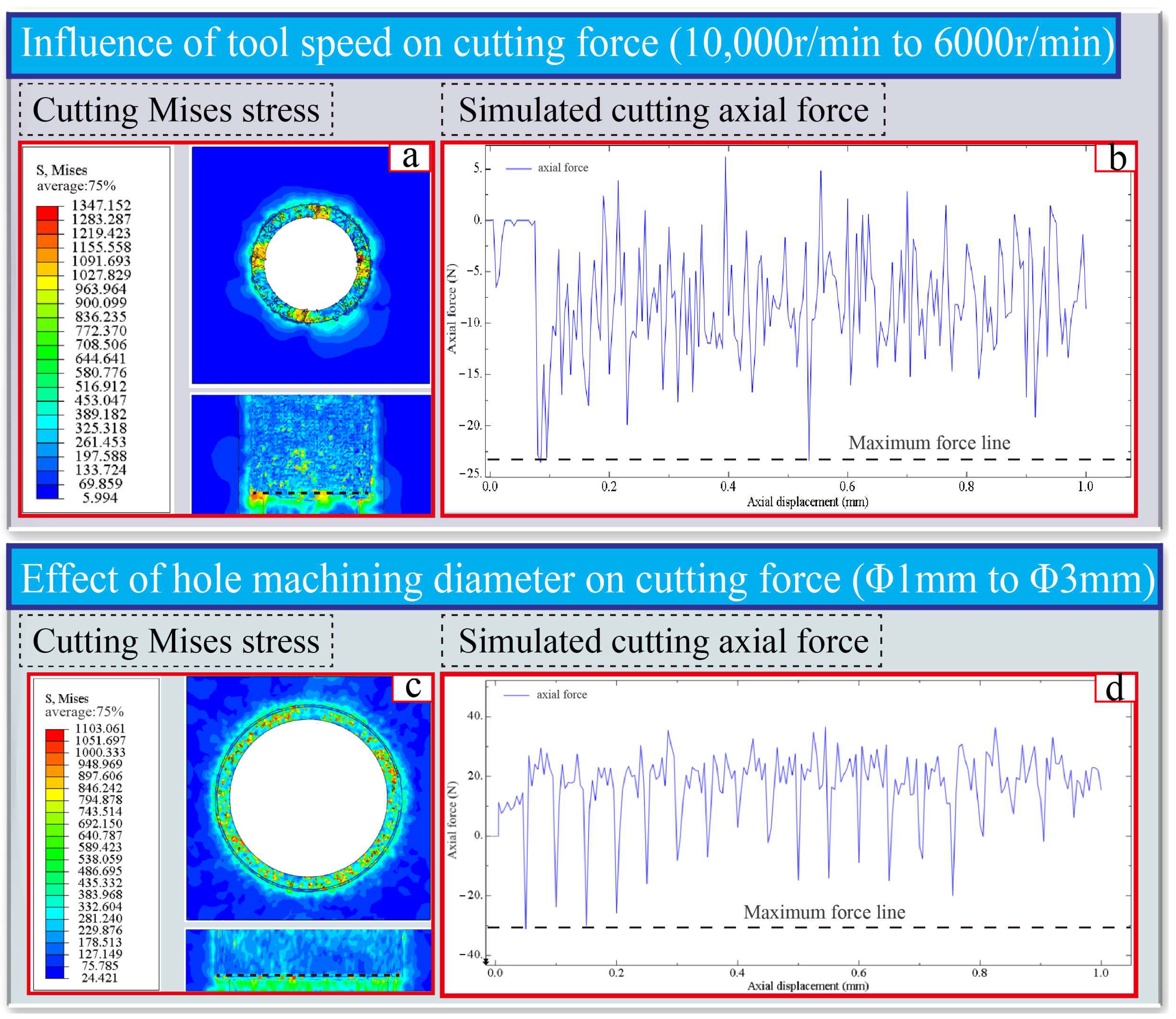
2.2. Constraint load and Result Analysis

According to the experiment installation position of the SLM-forming workpiece, the constraint position was determined as the two sides of the SLM workpiece model, and the constraint type was the full constraint. The constraint of this position can realize the workpiece’s effective positioning and facilitate the load’s application. In the milling simulation, the tool speed was set at 10,000 r/min, and the feed speed was 30 mm/min.
In Figure 4a,c, the initial moment of tool cutting in the SLM model was observed from the orifice and the inner wall, respectively. The tool had barely contacted the powder sticking at the SLM and formed a hole entrance when the workpiece had a significant stress shock. According to the cutting force simulation results in Figure 4g, the maximum stress was 1.256 GPa. It can be concluded that the impact axial force at the initial moment changes rapidly, with a maximum value of 22.5 N, as shown in Figure 4d. The maximum Mises stress distribution on the inner side of the hole wall when the tool cuts to the powder sticking on the hole wall can be obtained as 1.292 GPa, which appeared at the position of the powder sticking and gradually decreased along the center of the hole diameter. This is due to the presence of powder sticking; the material removal around the cutter edge is large, and the increase in cutting force leads to an increase in stress. In addition, the chip blockage caused by difficult chip removal further increases the cutting stress.
From the cutting force simulation results in Figure 4g, it can be concluded that the axial force increased sharply at about 0.3 s, and its maximum value reached 13 N. This is because there was more powder on the hole wall in the SLM workpiece model in Figure 4d. Cutting the cavity defect, the maximum Mises stress of the hole-wall profile was 1.325 GPa. With the horizontal extension of the cavity depth, the stress was transmitted to the interior of the cavity by material extrusion, and the stress value gradually decreased. As shown in Figure 4g, the axial force decreased to about 7 N when the molten cavity was cut in about 0.6 s.
In the process of milling the SLM workpiece with the milling cutter, when the cutter first contacted the workpiece, it mainly used the powder-sticking convex material to cut, with uneven contact stress and a large impact force. With the increased cutting depth, the cutting state gradually became stable, and the cutting force was maintained below 16 N. If the tool cut into more concentrated hole-wall powder, the cutting force would increase significantly. The cutting force clearly decreased as the tool cut into the molten cavity, as shown in Figure 4g.
This experiment also studied the influence of cutting speed on tool life and hole-wall quality. Figure 5a,b show the Mises stress and axial tool force of an SLM workpiece as the rotating speed is reduced from 10,000 r/min to 6000 r/min. Figure 5c,d show the influence of increasing the hole-machining diameter on tool life and hole-wall quality. The hole machining diameter was increased from a diameter of 1 mm to a diameter of 3 mm, the tool speed was 10,000 r/min, and the total size of the SLM workpiece model was 4 mm × 4 mm × 1 mm.
When the rotating speed was 10,000 r/min, the maximum Mises stress was 1.347 GPa, which occurred at the position of the material being cut by the cutter edge, and the stress value decreased with the cutter edge along the center of the hole diameter. When the tool rotational speed decreased from 10,000 r/min to 6000 r/min, the maximum axial force was about 23 N. When the tool speed was 10,000 r/min, the maximum axial force of 16 N was 43.75% higher than that when the tool rotational speed was 10,000 r/min, which obviously increased. This is because, with the reduction in the tool rotational speed, the cutting frequency was reduced, which made the single tooth cutting amount increase; the cutting-stress accumulation phenomenon was obvious, and the axial cutting force increased.
When the hole diameter increased from 1 mm to 3 mm, the axial force increased by 93.75%, and the maximum value was about 31 N, with a large increase, as shown in Figure 5d. This is due to the increase in the hole-machining diameter and the larger area of powder sticking and collapsing inside the hole diameter, which increased the material removal amount in unit time and thus increased the axial cutting force.
The simulation results show that during the process of milling simulation for the SLM workpiece model, the maximum stress often appeared at the contact position between the cutter edge and the material and decreased along the middle of the hole diameter. Cutting to the powder area of the hole wall increases the cutting stress in the powder area, and the axial force increases correspondingly. If the cutting reached the molten cavity area, the cutter edge would unload rapidly, the cavity material would be missing, and it would be difficult to diffuse to the interior so that the axial force would decrease correspondingly. Reducing the cutting speed or increasing the hole diameter would reduce the cutting frequency of the single tooth, increase the cutting amount, and then increase the axial force. This may result in reduced tool life.

3. SLM Hole-milling Experimental Research

3.1. SLM Sample Forming

In this experiment, TC4 titanium alloy spherical powder was prepared by the vacuum-assisted argon-atomization method [23]. The relevant appearance and composition are shown in Figure 6 and Table 3. The particle size of the powder is 15–53 μm. The relevant parameters of the SLM-formed metal laser 3D printer (AM400. Renishaw PLC, London, UK) used in the experiment are shown in Table 4. The selection of parameters such as laser power and scanning speed for preparing SLM samples was determined through preliminary experiments, as shown in Table 5.

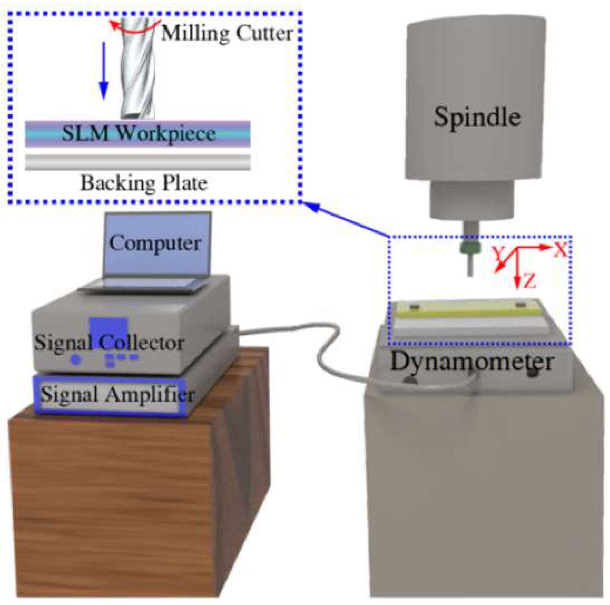
3.2. Processing and Experimenting Equipment

The milling hole-processing experiment equipment is a 0.1 μm rotary precision micro-precision engraving machine (Syntec EZ3M, Taiwan, China). The cutting-force measuring equipment is a Kistler9129A force-measuring instrument (measuring accuracy: 4 pC/N, Kistler, Switzerland) with a maximum sampling frequency of 2000 Hz. For the milled SLM sample, a Phenom scanning electron microscope (SEM, Phenom XL, integrated EDS function, resolution of 20 nm; Phenom, The Netherlands) was used to observe the inner wall after slitting along the hole, and a KEYENCE ultra-large depth-of-field digital microscope system (VHX-600 5000×, Keyence, Japan) was used to observe the surface appearance.

3.3. Experiment Plan

The machining experiment platform is shown in Figure 7. The force-measuring instrument Kistler9129A was used to collect the cutting force. The SLM-formed samples are shown in Figure 8, and the processing sequence was a diameter of 0.5 mm to a diameter of 3 mm with a step size of 0.5 mm. The rotation speed of the cutter for milling the hole diameter was 10,000 r/min–6000 r/min (step size is 1000 r/min), the axial feed speed of the cutter was set to 30 mm/min, the cutting depth was set to 3 mm, and the helix angle of the cutter used for hole machining was 55°. The coating was a four-edge carbide cutter with AlTiN.

4. Results and Analysis

4.1. Surface Appearance of SEM-Sample Milling Hole

As shown in Figure 9, the SLM directly forms the workpiece and the re-milled workpiece surface after SLM forming. The dimension accuracy of the re-milling hole after forming the workpiece is guaranteed, especially for high-precision positioning holes. The 0.5 mm-diameter of the 1.5-mm hole-profile SLM direct forming is not easy to observe. Due to the limitations of SLM-forming accuracy, under the current process conditions, when laser melting metal powder, the surface tension of liquid metal makes it appear as a small ball. The insufficient hole makes adjacent molten metals directly melt together under the effect of inter-molecular gravity, and the closed hole is formed by layer by layer cooling [6].
The SLM sample was observed and measured with an ultra-large depth-of-field digital microscope. The dimension accuracy and roundness of the re-milling hole after forming were better than those of the directly formed hole. Figure 10a–g show the diameter of the SLM direct forming hole, and Figure 10h–m show the diameter of the re-milling hole after forming. It can be concluded that the roundness of the hole diameter of SLM direct forming is poor, due to the lack of support on one side of the metal powder at the edge of the hole diameter during the SLM forming of the workpiece, accompanied by the melting collapse of some metal powder, the deviation of the laser focus, and the formation of obvious powder sticking at the edge of the hole after layer by layer melting and cooling. The hole profile is oval. Because SLM laser scanning is along the width direction of the sample, the secant lines in the width direction of the upper and lower positions of the hole are short, and the powders are fused together after melting and spheroidizing, while the secant lines in the width direction of the center of the hole are long. It is difficult for the hole powders to converge together after melting, so the hole profile directly formed by SLM is oval.
As shown in Figure 10g,n, the enlarged view of the surface of the diameter of a 3 mm hole directly formed by SLM shows obvious powder sticking, edge collapse, and laser scanning contour. The directly SLM-formed hole surface can be divided into four areas: the powder sticking area, collapse area, theoretical size, and actual size. The melting and collapse of materials cause some metal powder to stick directly to the collapse area, and the adhesion of such powders is large, as shown in Figure 10n. If the metal powder is not directly adhered to the collapse area, the adhesion force is small. Therefore, in order to obtain higher dimensional accuracy, the directly formed SLM hole diameter cannot meet the dimensional accuracy requirements, and the powder’s sticking area and collapse area should be removed by milling holes after forming.
Figure 10p depicts the dimensional accuracy of the directly formed SLM hole and re-milling hole after forming. It is concluded that the dimensional accuracy error of the directly formed SLM hole diameter reaches 20.578%, and the dimensional accuracy error of re-milling the hole after forming is only 3.633%. Re-milling a hole after forming can greatly improve the dimensional accuracy of hole machining and effectively remove powder sticking and collapse defects in additive manufacturing. Re-milling a hole after forming improves the surface accuracy of hole making. The prefabricated holes formed by SLM greatly reduce the amount of material removed during tool re-milling, reduce tool wear, and improve tool life and processing efficiency.
Using 1-mm and 3-mm diameter milling cutters to directly mill holes and re-milling holes after forming for SLM workpieces, respectively, and using SEM to observe, the following conclusions were drawn: the re-milling holes after forming had less burr and curl on the edge of the hole diameter, better roundness of the hole diameter, and less tool wear than the direct milling holes for SLM workpieces. As shown in Figure 11j, the surface of the direct milling hole was relatively rough, with many internal and external burrs and curls, and there was a spheroidized accumulation of surface materials on the right side. This is due to the fact that there are more materials to be removed per unit of time for direct milling, and the material flow and deformation are large. The major cutting edge and the minor cutting edge of the tool rub violently with the high-hardness TC4 titanium alloy to generate heat, and a small amount of melting and curling of the material around the hole diameter occurs. The continuous cutting of the tool’s minor cutting edge easily causes the tool to have radial runout, causing chip-removal difficulties and increased burrs. On the other hand, due to the serious spheroidization of the SLM sample surface, the tool directly milling the hole has a large initial vibration amplitude when contacting the SLM sample, and the profile of the hole entrance is rough. On the contrary, there was only a small amount of curl and burr on the hole entrance when re-milling the hole after forming it at a speed of 6000 r/min. At this time, there was less material to be removed per unit time, and only the powder-sticking area and collapse area needed to be removed. Because the adhesion was not firm, the cutting force required for SLM direct milling was much smaller, the material flow range was small, and the phenomenon of cutting heat accumulation was not easy to occur. In addition, the hole contour formed by SLM was scanned again by the laser. The spheroidization around the hole was greatly reduced, as shown in Figure 11a,i. When the tool speed was raised to 10,000 r/min, the melting and curling of materials around the hole diameter were greatly reduced, and the roundness of the hole diameter was good, as shown in Figure 11e,f.
For the direct milling of the SLM workpiece, due to the excessive amount of cutting, the hole burr, material accumulation, curling, and other phenomena are serious. At the same time, it is easy to aggravate tool wear and reduce tool life. The surface appearance of the hole diameter directly milled by a 1-mm diameter cutter at a rotating speed of 6000 r/min had an obvious burr phenomenon and accumulated material. The insufficient hole made the extrusion between the tool and the material obvious, and the material accumulates on the hole wall formed chips, which directly affected hole-size and shape accuracy, as shown in Figure 11d,l. As for the surface appearance of the re-milling hole after forming by a 1-mm diameter tool at a speed of 6000 r/min, due to lower material removal, the curl, burr, and material accumulation of the hole contour were reduced, and the shape accuracy was good, as shown in Figure 11c,k. When the tool speed was increased to 10,000 r/min, the cutting frequency of the tool major and minor cutting edges increased, the amount of material removed per unit time decreased, the material flow deformation was small, the burr on the hole contour was small, and the hole roundness was good, as illustrated in Figure 11g,h.

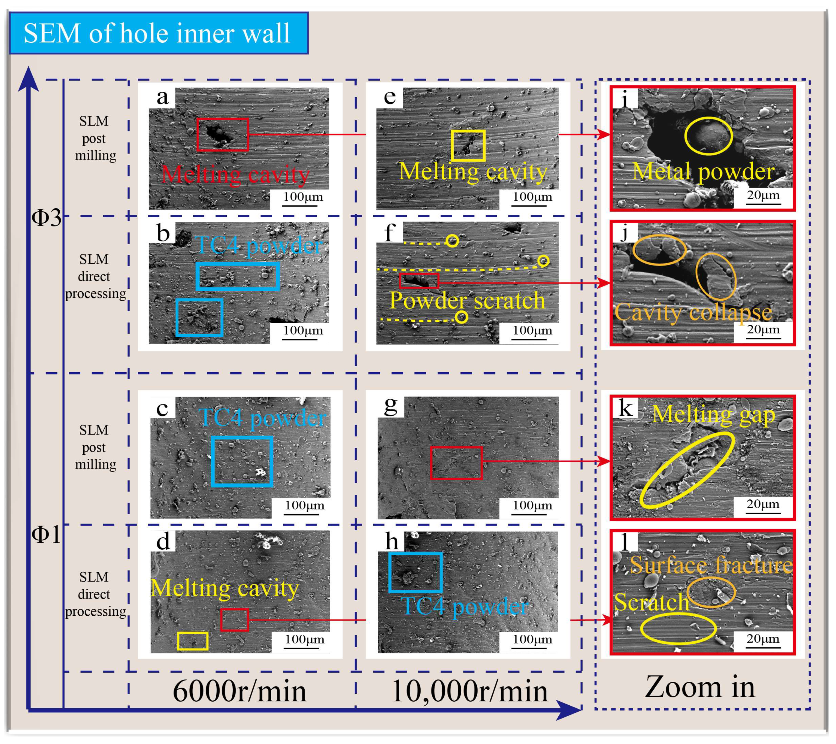
4.2. Hole-Wall Appearance

Using a 3-mm diameter milling cutter to mill holes for the SLM workpiece directly and then re-milling the hole after forming, cutting it open, and using SEM to observe the inner wall appearance of the hole, it was concluded that the inner wall of the hole made by a 3-mm milling cutter contained many molten holes. Internal molten holes are common defects in 3D printing. The hole-machining hole diameter was larger due to the randomness of hole defects, and more molten holes could be easily cut, as shown in Figure 12a. The inner wall appearance of the directly milled holes at a rotating speed of 6000 r/min was different from the inner wall appearance of the re-milled holes after forming. There was a large amount of TC4 metal powder on the surface, which was caused by the scraping and sticking of the powder during the cutting holes. However, due to the large amount of material removal, severe material flow and tool extrusion, and difficult chip removal, a large amount of powder adhered to the inner wall of the direct milling hole, affecting the surface quality of the hole-machining inner wall, as shown in Figure 12b. When the rotating speed of the tool was raised to 10,000 r/min, the powder scratches were severe. The extrusion of the cutting edge of the tool pair made the metal powder cling to the inner wall of the SLM sample hole, and with the rotation of the cutter edge, clear and regular scratches formed on the inner wall of the hole. The material at the edge of the hole was cracked and prone to collapse, and then the material peeled off, exacerbating the reduction in the quality of the inner wall of the hole diameter, as shown in Figure 12f,j. To sum up, re-milling holes after SLM forming significantly reduced the occurrence of powder sticking on the hole wall, powder scratches, powder embedding, hole-contour crushing, and other phenomena.
When the tool diameter was reduced to 1 mm, the amount of powder sticking on the inner wall of the hole and the phenomenon of melting holes were significantly reduced, and only a few melting cracks and surface cracks existed. This is due to the small probability of large holes during the drilling process with a 1-mm diameter milling cutter, but small closed gaps and surface-extrusion cracks were more likely to occur. The inner wall quality of the re-milling hole after SLM forming was better than that of the direct milling hole, as shown in Figure 12c,k, with less powder adhesion, good gap closure, and fewer powder scratches.
By comparing the inner wall quality of hole machining at a 6000 r/min rotating speed and 10,000 r/min rotating speed, as shown in Figure 12, it can be found that under high-speed cutting conditions, the powder adhesion was lower, the powder was finer, and the distribution was more uniform, which improved the hole-wall quality.

4.3. Cutting Force Analysis

The overall cutting force of the re-milling hole after SLM forming was smaller than that of SLM direct milling holes, and the axial force was the largest among the cutting forces, which affected tool wear and service life. With the reduction in cutting speed or the increase in tool diameter, the cutting force has had a significant increasing trend.
Figure 13a depicts the change curve of cutting force in the X and Y directions when a 0.5-mm milling cutter was milling holes at various speeds. The cutting force in the X direction was relatively large, about 10 N. The cutting force in the Y direction was relatively small, about 5 N. This is because the milling cutter with a helix angle of 55° cuts clockwise when observed along the Z direction of workpiece clamping. At this time, the component force in the X direction was greater than that in the Y direction, which will cause the force in the X direction to be greater than that in the Y direction. The cutting force of a re-milling hole after forming was slightly less than that of SLM direct milling holes, which was due to the greater material removal of SLM direct milling holes. The cutting force of re-milling holes after forming or direct milling holes increases with the reduction in the cutting speed of the tool. This is because when the cutting speed decreases, the material removal amount of the tool’s major cutting edge and the tool’s minor cutting edge increases, and then the cutting force increases. The maximum axial force of the milling hole with a diameter of 0.5 mm was about 20 N, which was significantly greater than the cutting force in the X and Y directions. As shown in Figure 13b, a large axial force reduces the surface quality of the inner wall of the milling hole, intensifies tool wear, and shortens tool life.
At different speeds, the X-direction cutting force of a 3-mm diameter milling cutter was greater, with a maximum cutting force of about 10 N, while the Y-direction cutting force was smaller, with a maximum cutting force of about 5 N, which was consistent with the hole-milling rule of a 0.5-mm diameter milling cutter, as shown in Figure 13c,d. As shown in the appearance of the 3-mm-diameter hole in Figure 10, the hole diameter formed by SLM will not cause melt sealing due to the increase in the hole diameter. At this time, the quantity of material removal for the re-milling hole after forming was smaller than that of the directly milled hole by SLM, and the stress in three directions was significantly reduced. As shown in Figure 13d, due to the reduction in cutting amount, the axial force of re-milling holes after forming was significantly lower than that of SLM direct-milling holes, which was conducive to reducing tool wear and increasing service life.
The axial forces of the re-milling hole after forming were compared, as shown in Figure 14a. The axial force for a diameter of 1.5 mm and a diameter of 2 mm was smaller, and the axial force for a diameter of 0.5 mm/1 mm/2.5 mm/3 mm was larger. In the material-removal area, as shown in Figure 14d, the cutting force was positively correlated with the material-removal rate during SLM milling. The material-removal portion is ( S t S a ) . The smaller the k value of a hole, the smaller the area occupied by the area to be machined, the smaller the cutting area of the tool, and the smaller the corresponding cutting force, and vice versa.
Figure 14c shows the hole state. A type I hole state existed in the small diameter holes formed by SLM, such as those of a diameter of 0.5 mm/1 mm. At this time, the hole was fused and sealed. A type Ⅱ hole state exists in the larger diameter holes formed by SLM, such as those with a diameter of 2.5 mm/3 mm. At this time, there were many hole collapses and occurrences of powder sticking, but no hole closure was formed. The type III hole state was that no preformed hole was left in SLM forming, and the hole was directly milled. The k values for the diameter of 2.5 mm and 3 mm holes, belonging to the type II state, can be calculated for the material to be processed, composed of the collapse area and the powder-sticking area in Figure 10g, and the axial force was between 10 N and 15 N. When the diameter is increased, the conclusion is consistent.
To sum up, in the process of SLM hole machining, the cutting force of direct milling was greater than that of the re-milled hole after forming, which was mainly reflected in the axial force. When the cutting speed was higher, the hole diameter was smaller, the material-removal rate under the same hole diameter was smaller, and the axial force was reduced, which is conducive to improving the quality of the hole-machining inner wall and improving the tool life. If the material-removal rate is consistent, the larger the hole diameter, the greater the corresponding cutting axial force. When compared with the axial force data obtained from the milling simulation analysis and experiment, it can be seen that the SLM workpiece model was more accurate, the axial force error obtained from the simulation and experiment was small, and the variation law was basically consistent. The milling simulation better verifies the conclusion that the cutter speed decreases or the hole diameter increases, making the axial force increase.

5. Conclusions

Additive and subtractive manufacturing integrates the advantages of additive manufacturing and subtractive processing and can effectively improve the size, shape, and position accuracy of holes. The following conclusions were drawn:
1. An SLM workpiece model with the characteristics of collapse, powder sticking, and cavity defects was established, and a milling simulation analysis was carried out. The results show that at the initial moment, the Mises stress in the powder-sticking area of the tool cutting reached 1.256 GPa, and the maximum axial force was 22.5 N. With the stability of the cutting state, the axial force decreased and stabilized at about 10 N. If the tool cut the sticky powder or cavity, the stress would increase. If the hole diameter increased or the cutting speed decreased, the axial force would be increased significantly.
2. The dimensional accuracy of the re-milling hole after forming was 16.945% higher than that of direct forming. There was less burr, curling, and material accumulation at the hole entrance of the re-milling hole after forming, and there was less powder sticking and fewer scratches on the hole wall. With the increase in the milling-hole diameter and the tool speed, such defects were significantly reduced.
3. The cutting force of direct milling was 50.1% higher than the axial force of the re-milling hole after forming. When the cutting speed of the tool increased, the hole diameter decreased, and the material-removal rate under the same hole diameter decreased, reducing the axial force, which was conducive to improving the quality of the inner wall of the machined hole. The hole-machining experiment of the SLM workpiece was basically consistent with the cutting simulation analysis of cutting speed, hole size, and axial force variation, which further verified the accuracy of the model SLM-hole-machining simulation.

Author Contributions

W.S.: Data curation, Writing original draft, Writing review and editing. T.Y.: Data curation, Formal analysis, Methodology, Writing original draft, Writing review editing. Y.L.: Investigation, Resources, Supervision, Writing review and editing. X.Z.: Investigation, Resources, Supervision. J.L.: Investigation, Resources, Supervision. L.W.: Investigation, Resources, Supervision. L.D.: Data curation, Validation, Visualization. All authors have read and agreed to the published version of the manuscript.

Funding

This research was funded by the National Natural Science Foundation of China (51975006, 51505006), the National Key R&D Program of China (2022YFC2406004). and 2022 Beijing Technology and Business University Graduate Research Ability Enhancement Program project grant (126).

Institutional Review Board Statement

Not applicable. This study does not require ethical approval, and does not involve human or other animal experiments and research.

Informed Consent Statement

Not applicable.

Data Availability Statement

Not applicable.

Conflicts of Interest

The authors declare no conflict of interest.

References

  1. Aboulkhair, N.T.; Simonelli, M.; Parry, L. 3D printing of Aluminium alloys: Additive Manufacturing of Aluminium alloys using selective laser melting. Prog. Mater. Sci. 2019, 106, 100578. [Google Scholar] [CrossRef]
  2. Attaran, M. The rise of 3-D printing: The advantages of additive manufacturing over traditional manufacturing. Bus. Horiz. 2017, 60, 677–688. [Google Scholar] [CrossRef]
  3. Khorasani, M.; Ghasemi, A.; Rolfe, B.; Gibson, I. Additive manufacturing a powerful tool for the aerospace industry. Rapid Prototyp. J. 2022, 28, 87–100. [Google Scholar] [CrossRef]
  4. Liu, H.; Sun, Y.; Geng, Y.; Shan, D. Experimental research of milling force and surface quality for TC4 titanium alloy of micro-milling. Int. J. Adv. Manuf. Technol. 2015, 79, 705–716. [Google Scholar] [CrossRef]
  5. Li, M.; Yu, T.; Zhang, R.; Yang, L.; Li, H.; Wang, W. MQL milling of TC4 alloy by dispersing graphene into vegetable oil-based cutting fluid. Int. J. Adv. Manuf. Technol. 2018, 99, 1735–1753. [Google Scholar] [CrossRef]
  6. Mukherjee, T.; Zhang, W.; DebRoy, T. An improved prediction of residual stresses and distortion in additive manufacturing. Comput. Mater. Sci. 2017, 126, 360–372. [Google Scholar] [CrossRef] [Green Version]
  7. Ma, J.-W.; Jiang, W.-W.; Ye, T.; Song, J.-P.; He, G.-Z. An analysis method of cutting heat by transforming from time-varying variable to constant parameter for dry milling of TC4 curved surface. Int. J. Adv. Manuf. Technol. 2019, 103, 2133–2150. [Google Scholar] [CrossRef]
  8. Liu, J.; Song, J.; Chen, Y.; Zhang, J.; Wu, L.; Wang, G.; Zhang, F.; Liu, Z.; Sun, J.; Liu, S.; et al. Atmospheric pressure cold plasma jet–assisted micro-milling TC4 titanium alloy. Int. J. Adv. Manuf. Technol. 2021, 112, 2201–2209. [Google Scholar] [CrossRef]
  9. Du, W.; Bai, Q.; Zhang, B. A Novel Method for Additive/Subtractive Hybrid Manufacturing of Metallic Parts. Procedia Manuf. 2016, 5, 1018–1030. [Google Scholar] [CrossRef] [Green Version]
  10. Zhao, H.T.; Gao, M.Q.; Zhao, J.B. Study on Thermo Mechanical Coupling of the Hybrid Additive and Subtractive Manufacturing Based on Finite Element Model. J. Mech. Eng. 2022, 58, 274–282. [Google Scholar]
  11. Yang, Y.Y.; Gong, Y.D.; Qu, S.S. Experiment on the Macro-morphology and residual Stress of 316L by Hybrid Additive and Subtractive Manufacturing. J. Northeast. Univ. (Nat. Sci.) 2020, 41, 380–386. [Google Scholar]
  12. Fortunato, A.; Lulaj, A.; Melkote, S.; Liverani, E.; Ascari, A.; Umbrello, D. Milling of maraging steel components produced by selective laser melting. Int. J. Adv. Manuf. Technol. 2018, 94, 1895–1902. [Google Scholar] [CrossRef]
  13. Yang, X.; Ma, Y.; He, D.; Du, X.; Wang, R. Theoretical Analysis and Experimental Research into the Mechanical Properties of Al-Ti-Al Symmetrical Laminated Plate. Adv. Mater. Sci. Eng. 2020, 2020, 8942585. [Google Scholar] [CrossRef] [Green Version]
  14. Tao, W.; Jin, Z.; Shuai, J.; Fen, Y. Effect of laser scanning and milling speed on surface roughness of TC4 hybrid prepared. Int. J. Adv. Manuf. Technol. 2021, 117, 1663–1674. [Google Scholar] [CrossRef]
  15. Zhang, C.; Zhao, B.; Zhao, C. Effect of ultrasonic vibration-assisted face milling on the surface microstructure and tribological properties. J. Vibroeng. 2022, 24, 1–17. [Google Scholar] [CrossRef]
  16. Sanaei, N.; Fatemi, A. Defects in additive manufactured metals and their effect on fatigue performance: A state-of-the-art review. Prog. Mater. Sci. 2020, 117, 100724. [Google Scholar] [CrossRef]
  17. Tillmann, W.; Schaak, C.; Nellesen, J.; Schaper, M.; Aydinöz, M.; Hoyer, K.-P. Hot isostatic pressing of IN718 components manufactured by selective laser melting. Addit. Manuf. 2017, 13, 93–102. [Google Scholar] [CrossRef]
  18. Galati, M.; Iuliano, L. A literature review of powder-based electron beam melting focusing on numerical simulations. Addit. Manuf. 2018, 19, 1–20. [Google Scholar] [CrossRef]
  19. Liu, Z.; Yue, C.; Li, X.; Liu, X.; Liang, S.; Wang, L. Research on Tool Wear Based on 3D FEM Simulation for Milling Process. J. Manuf. Mater. Process. 2020, 4, 121. [Google Scholar] [CrossRef]
  20. Zou, Z.; Zhao, X.; He, L.; Jiang, X. Study of Different Micro Milling Blades on Milling Titanium Alloy TC4. IOP Conf. Ser. Mater. Sci. Eng. 2020, 751, 012082. [Google Scholar] [CrossRef]
  21. Deng, Y.F.; Zhang, Y.; Zhang, W.Q. Effects of Fracture Criterion on TC4 Titanium Alloy Plates against Impacts of Ogival-nosed Projectiles. China Mech. Eng. 2019, 30, 2378–2384. [Google Scholar] [CrossRef]
  22. Deng, Y.F.; Zhang, Y.; An, J.D. Mechanical properties and constitutive relationship of TC4 titanium alloy. J. Vib. Shock 2020, 39, 70–77. [Google Scholar] [CrossRef]
  23. Lu, X.; Lin, X.; Chiumenti, M.; Cervera, M.; Hu, Y.; Ji, X.; Ma, L.; Yang, H.; Huang, W. Residual stress and distortion of rectangular and S-shaped Ti-6Al-4V parts by Directed Energy Deposition: Modelling and experimental calibration. Addit. Manuf. 2019, 26, 166–179. [Google Scholar] [CrossRef]
Figure 1. Comparison between SLM workpiece finite element model and actual defects: (a) the actual collapse defect; (b) the actual sticky powder defect; (c) the actual melting cavity defect; (d) the modeling collapse defect; (e) the actual sticky powder defect; (f) the actual melting cavity defect.
Metals 12 01919 g001
Figure 2. Finite element model size and load constraints: (a) the model structure; (b) the model size; (c) the loads and constraints.
Metals 12 01919 g002
Figure 3. Material stress–strain curve.
Metals 12 01919 g003
Figure 4. Milling-hole simulation machining: (ab) the Mises stress at end face; (a) the initial cutting position; (b) the bottom cutting position. (cf) the Mises stress of hole section; (c) the initial cutting position; (d) the cutting sticky powder; (e) the cutting cavity; (f) the bottom cutting position. (g) the cutting simulation axial force. The spindle speed 10,000 r/min and the tool diameter is 1 mm.
Metals 12 01919 g004
Figure 5. Influence of tool speed on cutting force: (a) the cutting Mises stress; (b) the simulated cutting axial force; the spindle speed 6000 r/min and the tool diameter is 1 mm. (c) the cutting Mises stress; (d) the simulated cutting axial force; the spindle speed 10,000 r/min and the tool diameter is 3 mm.
Metals 12 01919 g005
Figure 6. SEM appearance of TC4 titanium alloy powder particles.
Metals 12 01919 g006
Figure 7. Dynamometer installation platform.
Metals 12 01919 g007
Figure 8. Sample of SLM forming.
Metals 12 01919 g008
Figure 9. SEM-sample milling-hole drawing: (a) the SEM forms directly; (b) the SEM forming after milling.
Metals 12 01919 g009
Figure 10. Hole size accuracy and SLM-forming zone: (af,g) the hole size of SLM direct forming; (ag) the hole size is 0.5 mm–3 mm in sequence, and the step length is 0.5 mm. (hm) the hole size of SLM direct forming; (hm) the hole size is 0.5 mm–3 mm in sequence, and the step length is 0.5 mm. (g) the blown up view of directly formed holes; (n) the area classification of formed holes; (p) the hole size statistics.
Metals 12 01919 g010
Figure 11. SEM of the hole-end surface: (ad) the spindle speed is 6000 r/min. (eh) the spindle speed is 10,000 r/min. (a,e) SLM post milling with 3 mm milling cutter; (b,f) SLM direct processing with 3 mm milling cutter; (c,g) SLM post milling with 1 mm milling cutter; (d,h) SLM direct processing with 1 mm milling cutter. (i) enlarged view of (e); (j) enlarged view of (b); (k) enlarged view of (c); (l) enlarged view of (d).
Metals 12 01919 g011
Figure 12. SEM of hole inner wall: (ad) the spindle speed is 6000 r/min. (eh) the spindle speed is 10,000 r/min. (a,e) SLM post milling with 3 mm milling cutter; (b,f) SLM direct processing with 3 mm milling cutter; (c,g) SLM post milling with 1 mm milling cutter; (d,h) SLM direct processing with 1 mm milling cutter. (i) enlarged view of (a); (j) enlarged view of (f); (k) enlarged view of (g); (l) enlarged view of (d).
Metals 12 01919 g012
Figure 13. Cutting-force change curve: comparing different hole-forming methods. (a) X- and Y-direction cutting force of milling cutter with a diameter of 0.5 mm; (b) Z-direction cutting force of milling cutter with diameter of 0.5 mm; (c) X- and Y-direction cutting force of milling cutter with diameter of 3 mm; (d) Z-direction cutting force of milling cutter with diameter of 3 mm.
Metals 12 01919 g013
Figure 14. Variation law and mechanism of cutting force: (a) the Z-direction force changes with the decrease in spindle speed when the milling cutter with diameter of 0.5 mm–3 mm performs SLM post milling; (b) the Z-direction force changes with the decrease in spindle speed when the milling cutter with diameter of 0.5 mm–3 mm performs SLM direct milling; (c) the three hole states; (d) the actual size and theoretical size of hole.
Metals 12 01919 g014
Table 1. TC4 titanium alloy basic parameters.
E(MPa)μ ρ /(kg/m3) A/MPaB/MPanCm
110,0000.3445008623310.340.00.0
Table 2. J–C constitutive model parameters of TC4 titanium alloy.
d1d2d3d4d5Tm ε ˙ 0
00.330.480.0043.901
Table 3. Chemical composition of TC4 titanium alloy powder.
ElementTiAlVFeCNHO
Wt.%Balance5.5–6.53.5–4.50.250.080.030.01250.13
Table 4. Equipment parameters of metal laser 3D printer.
Maximum Power (W)Laser Wave Length (nm)Laser Beam Diameter (μm)Maximum Dimensions (mm)
400107570250 × 250 × 300
Table 5. SLM-forming parameters.
ParameterLaser Power (W)Exposure Time (μs)Point Distance (μm)Hatch Space (mm)Scanning Speed (mm/s)Layer Thickness (μm)
Value270100500.0750050
Publisher’s Note: MDPI stays neutral with regard to jurisdictional claims in published maps and institutional affiliations.

