Article

Numerical Simulation and Application of Tundish Cover Argon Blowing for a Two-Strand Slab Continuous Casting Machine

1
State Key Laboratory of Vanadium and Titanium Resources Comprehensive Utilization, Panzhihua 617000, China
2
Pangang Group Xichang Steel and Vanadium Co., Ltd., Steelmaking Plant, Xichang 615000, China
3
Sustainable Minerals Institute, The University of Queensland, 80 Meiers Road, Indooroopilly, QLD 4068, Australia
*
Authors to whom correspondence should be addressed.
Metals 2022, 12(11), 1801; https://doi.org/10.3390/met12111801
Submission received: 19 September 2022 / Revised: 8 October 2022 / Accepted: 19 October 2022 / Published: 24 October 2022
(This article belongs to the Special Issue Fundamentals of Advanced Pyrometallurgy)

Abstract

:
During continuous casting, argon blowing from tundish cover (ABTC) can greatly prevent the flow of the remaining air and decrease the reoxidation of molten steel in tundish. In the current study, a numerical model based on a tundish of a two-strand slab continuous casting machine was established to investigate the feasibility and evaluate the protective casting effect of the ABTC process. The influence of operation parameters, including sealing schemes of tundish cover holes and the argon flow rate of the remaining oxygen content, were studied in tundish. Then, industrial trials based on the operation parameters from the numerical model were carried out to evaluate the protective effect of ABTC. The results indicate that the ABTC process has a great protective effect in avoiding increasing levels of nitrogen and losing titanium and aluminum. With the ABTC process applied, the average increment of nitrogen (△w[N]) in steel from the end of RH to tundish decreases by 90% from 10 × 10−6 to 1 × 10⁻⁶, the average loss of titanium (△w[Ti]) by 12.7% from 63 × 10−6 to 55 × 10−6, and the amount of aluminum (△w[Al]) decreases by 7.1% from 70 × 10−6 to 55 × 10−6. The injecting hole and baking holes should be sealed during the period of empty tundish to efficiently discharge the air. In order to ensure that the oxygen volume fraction in tundish is less than 1%, the argon flow rate should be ≥220 Nm3/h during the period of empty tundish and ≥80 Nm3/h during the period of normal casting.

1. Introduction

High-cleanliness steel has been developed from advanced steel materials with the rapid expansion of transportation, national defense and marine engineering [1,2]. The number of oxide inclusions in molten steel is directly proportional to the total oxygen content of molten steel, which is usually treated as an indicator to evaluate the number of oxide inclusions. Although the purity of molten steel can be greatly improved by the refining of ladle [3,4,5], abundant oxide inclusions will produce and deteriorate the purity of molten steel if the protective casting is poor.
In the field of steel production, argon as a protective gas has been widely used in the process of continuous casting. The application of argon in ladle stirring [6,7,8,9,10], RH [11,12], the argon bubbling curtain [13,14] in tundish, and submerged entry nozzle [15,16,17,18] has provided a great protective effect on removing inclusions and alleviating the clogging of SEN (Submerged Entry Nozzle). However, the secondary oxidation of molten steel cannot be avoided in the early casting stage of the first ladle after baking tundish due to the untimely melt of protective slag. Argon blown into tundish from pipes installed on the tundish cover, as a kind of important protective casting process, plays an important role in decreasing the secondary oxidation of molten steel and improving its cleanliness. During the initial casting period after baking tundish, blowing argon into tundish and discharging air may prevent the molten steel from being reoxidized before the protective slag is fully melted. Wang [19] conducted a plant trial in Tang steel and found that the protective casting effect can be greatly improved when the residual oxygen volume fraction in tundish is less than 1%. Story [20] found that the loss of aluminum in molten steel may be decreased by 87.5% with argon blowing into tundish during the whole period of continuous casting. Considering the advantages of the process, some plants in Europe and Japan have been applied in industrial production and shown good effects [21]. For example, the defect rate of IF steel in Corus decreased by 38%, and the quantity of inclusions along the casting direction in POSCO significantly decreased after applying this process. Some plants in China have also adopted this process. Han Steel reported the average content of inclusions in low-carbon steel decreased from 0.47% to 0.32%. Gao [22] found the surface defect production rate of deep-drawing steel decreased from 7.78% to 2.62% as the diameter of argon blowing pipe increased from 20 mm to 34 mm.
Although ABTC has been applied in some plants, the numerical investigation and application assessment of ABTC has rarely been reported in the literature. Therefore, the current study aims to investigate the feasibility and evaluate the protective casting effect of ABTC during a continuous casting period. Firstly, a three-dimensional numerical model based on the practical two-strand slab tundish of the Pangang Group was built to investigate the behavior of oxygen volume fraction under different sealing schemes and argon flow rates during a period of empty tundish and normal casting. Then, plant trials based on the numerical simulation results and steel grade of M3A35 were carried out, where the increased nitrogen content and the loss of titanium and aluminum at the end of the RH process and tundish were tested to evaluate the protective casting effect.

2. Model Description

2.1. Governing Equations and Boundary Conditions

In order to simplify the numerical model and reduce its calculation time, the following assumptions were made:
  • The argon blown into the tundish and the air remaining in the tundish were regarded as incompressible fluids.
  • The whole process of protective casting was regarded as isothermal, and the energy loss of tundish was ignored due to the high temperature in tundish after baking and the low specific heat capacity of argon and air.
  • The temperature of argon blown into tundish was assumed to be the same as that of tundish, and the natural convection in tundish was ignored.
  • The effect of argon flow on molten steel and slag was ignored.
The flow of gas in tundish during the process of protective casting can be described by the following governing Equations:
ρ t + · ρ u = 0
t ρ u + · ρ u u = p + · μ + μ t u + u T + ρ g
where ρ is the mixture gas density, kg/m3; t is time, s; u is the velocity vector of mixture gas, m/s; p is the local pressure, Pa; μ is the mixture viscosity, kg·m−1·s−1; μt is the turbulent viscosity, kg·m−1·s−1; and g is the gravitational acceleration, m·s−2.
The standard two-equation k-ε model with scalable wall function is applied to describe the turbulent behavior of flow field, where the equation of turbulent kinetic energy transport and its dissipation rate transport can be solved to obtain the turbulent viscosity:
μ t = ρ C μ k 2 ε
Turbulent kinetic energy, k, m2·s−2:
ρ k t + · ρ u k = · μ + μ σ k k + G k ρ ε
where G is the generation of turbulent kinetic energy due to the mean velocity gradients and can be written as:
G k = μ t u j x i u i x j + u j x i
The dissipation rate of turbulent kinetic energy, ε, m2·s−3:
ρ ε t + · ρ u ε = · μ + μ t σ ε ε + ε k C 1 G C 2 ρ ε
where C1, C2, Cμ, σk, σε are the empirical constants, whose values, as recommended by Launder and Spalding [23], are 1.38, 1.92, 0.09, 1.0, and 1.3, respectively.
The species transport equation was solved to obtain the volume fraction of air and argon, and then the volume fraction of oxygen can be obtained by the product of air volume fraction and 0.21 (the volume fraction of oxygen in air):
t ρ Y i + · ρ u Y i = · ρ D i , m + μ t S c t Y i + S i
where Yi is mass fraction for species i, non-dimensional; Di, m is the mass diffusion coefficient for species i, m2·s−1; Sct is the turbulent Schmidt number, 0.7; Si is the source term for species i, kg·(m−3·s−1); and in the current study, i represents argon or air in tundish.

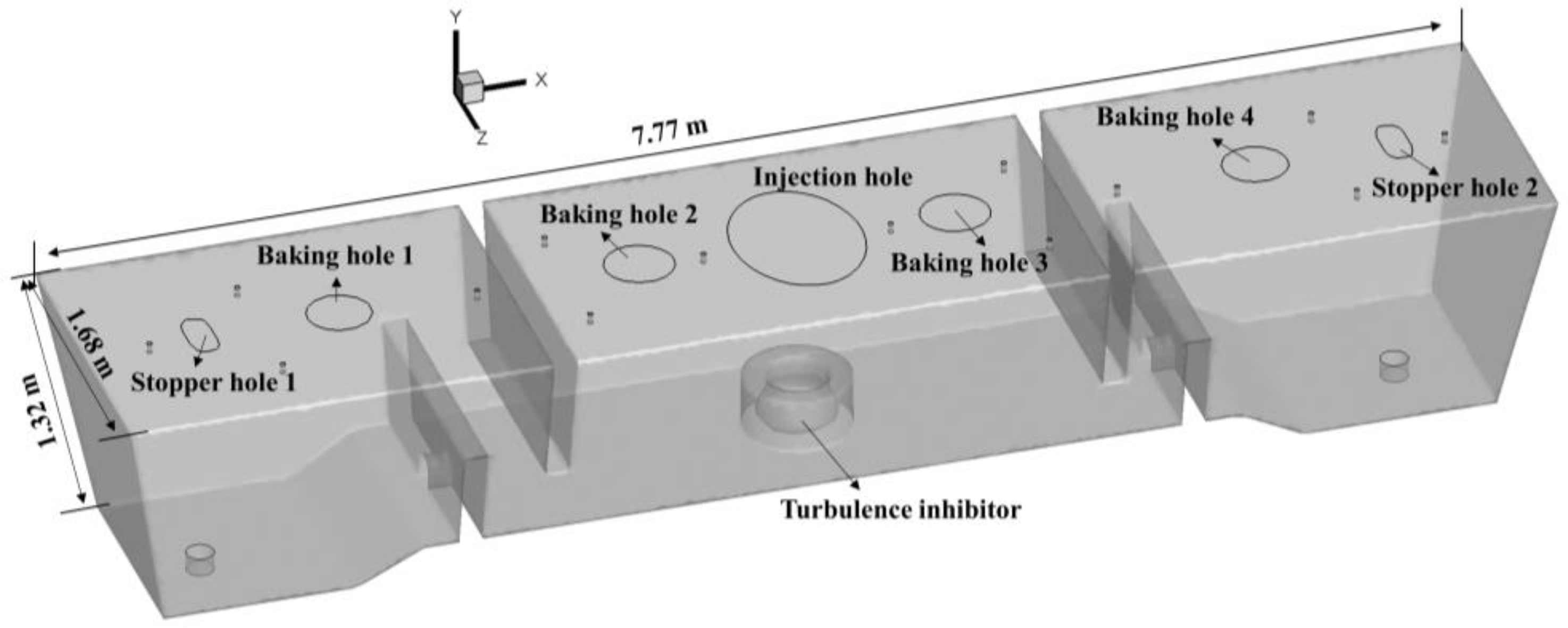
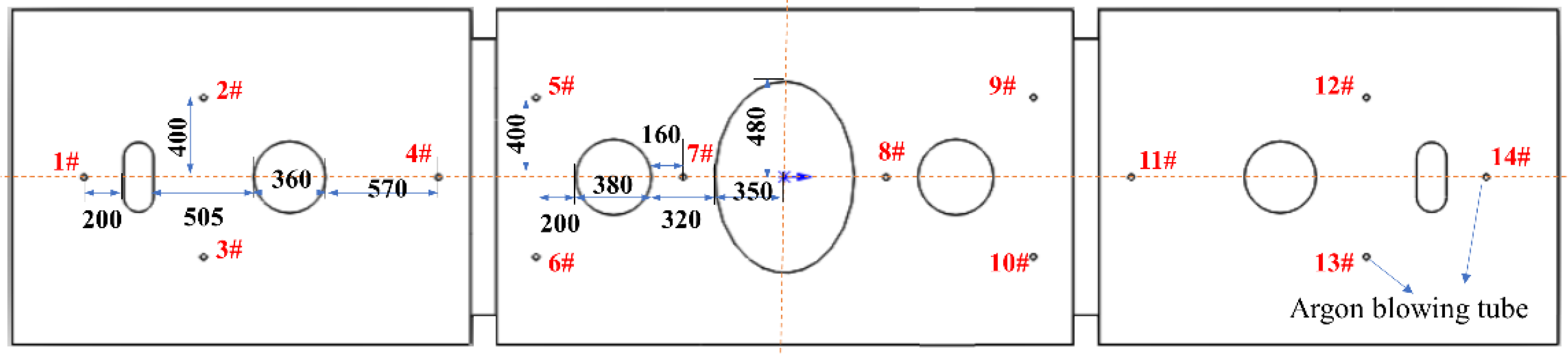
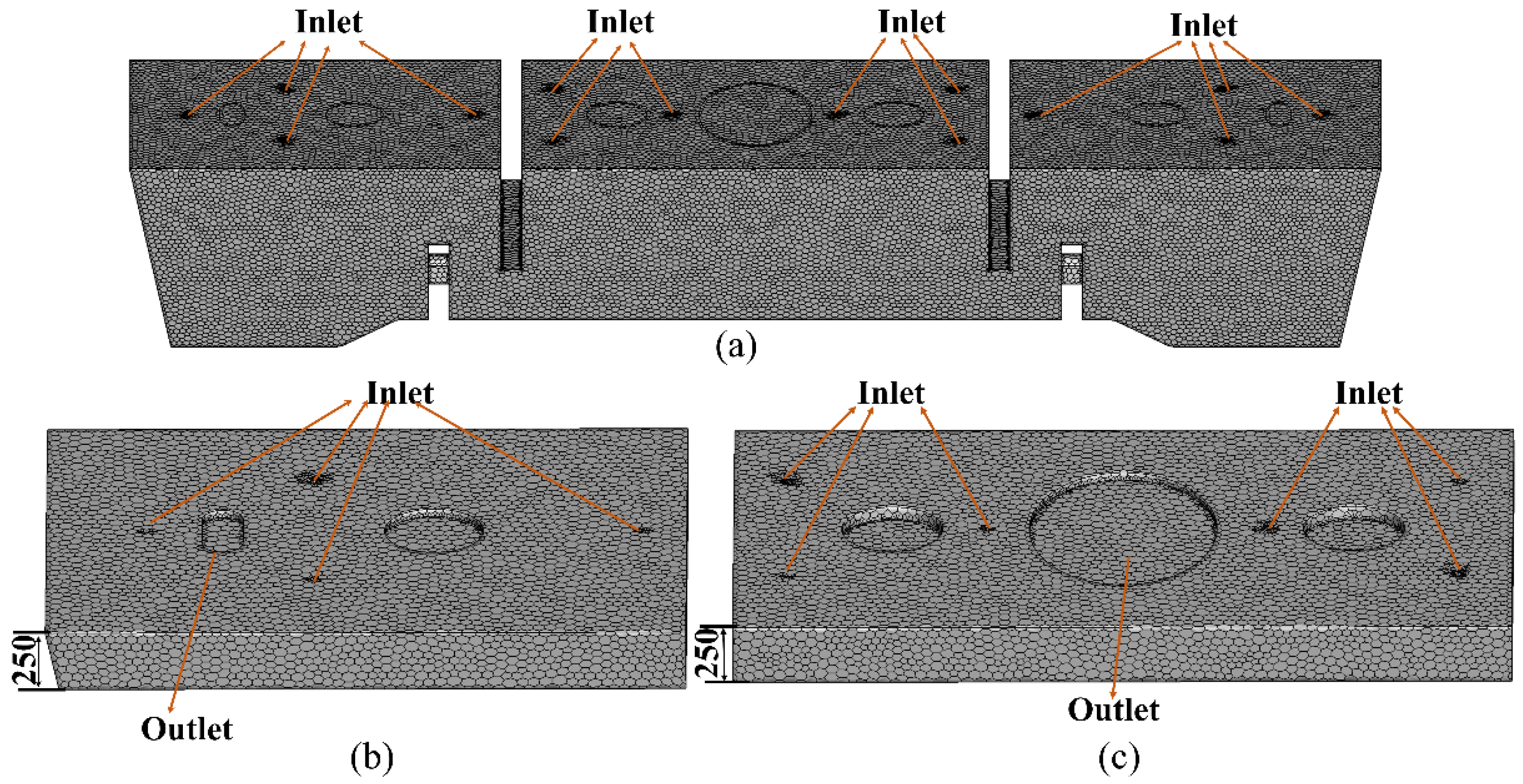
2.2. Experimental Facility and Numerical Model

Figure 1 shows the two-strand slab tundish schematic diagram. A tundish with a size of 7.77 × 1.68 × 1.32 m and a taper of 1.1 between the top face and bottom face has an injecting chamber and two symmetrical casting chambers. The injecting chamber has two baking holes, and each casting chamber has a baking hole and a stopper hole. The tundish cover is composed of an outer shell made of steel plates and filler made of refractory material. The argon pipe is buried inside the refractory material. Figure 2 shows the arrangement of the argon blowing pipe in the tundish cover. Fourteen argon blowing pipes with diameters of 30 mm were installed on the tundish cover, including six for the injecting chamber and four for each casting chamber. Before a tundish is used, the blast furnace gas is first adopted to bake the tundish through those baking holes for more than 30 min to completely eliminate water vapor. After baking the tundish, its temperature was greater than 1000 K. The process of ABTC will be conducted after baking tundish. Because the covering flux on the molten steel surface cannot be fully melted immediately, argon blown into tundish through those pipes may remove air and reduce molten steel secondary oxidation. During the period of empty tundish and normal casting, it is necessary to maintain the volume fraction of oxygen in tundish at a low level (<1%) to avoid the secondary oxidation of molten steel and improve its cleanliness.
During the period of empty tundish, the gas can be freely exchanged between the injecting chamber and casting chamber. However, during the period of normal casting, the injecting chamber and casting chamber are isolated by molten steel, which forms a separate injecting chamber and two separate casting chambers, in which the gas cannot exchange. Therefore, the mesh for the empty tundish and normal casting must be built separately. The mesh for empty tundish and normal casting is shown in Figure 3. Octahedron grids are adopted to a mesh in the calculating domain, and the numbers of meshes are 508,484 for empty tundish, 41,018 for isolated casting chamber, and 52,493 for isolated injecting chamber.
During the calculation, the velocity inlet boundary condition was used for those argon pipes, where the argon flow rate of each pipe is 1/14 of the total flow rate. The pressure outlet with a relative static pressure of zero was adopted for the opening hole, which is decided by the sealing scheme in the stage of empty tundish and the injecting hole and stopper hole in the normal casting according to the practical process. The non-slip wall boundary was used for all inner faces of tundish, which assumes that the gas velocity on the wall is zero. The initial condition of air volume fraction and temperature is assumed as 1 and 1000 K, respectively. The SIMPLEC algorithm was adopted to solve the transient problem. The timestep was set to 0.05 s for the current study. Calculation convergence was achieved when all residuals were lower than 10−4. The average volume fraction of oxygen is monitored throughout the calculation process. The tundish parameters and other related continuous casting process parameters are summarized in Table 1.

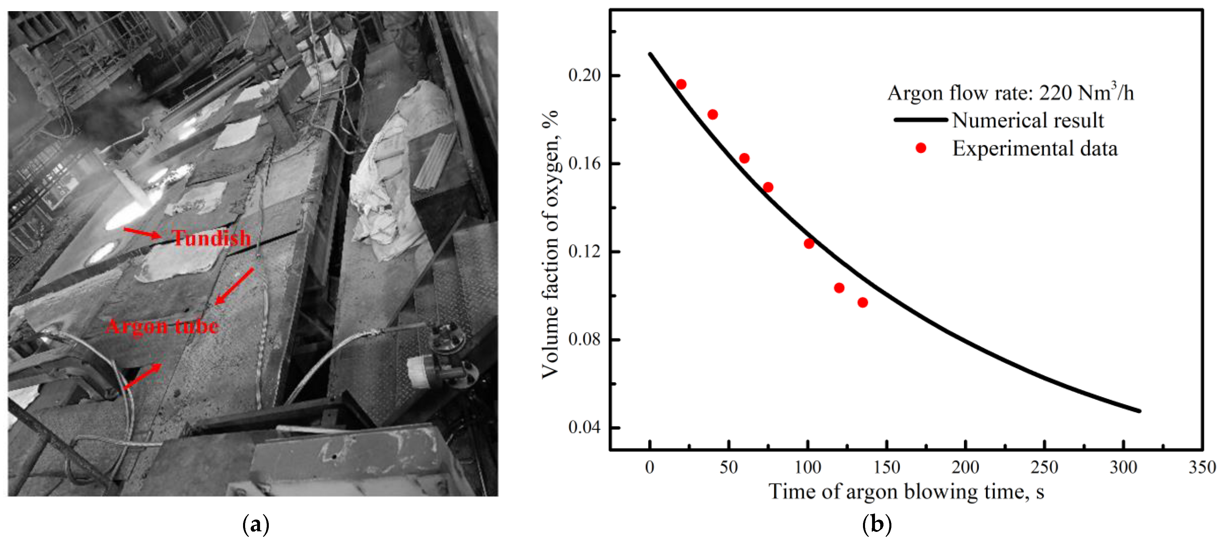
2.3. Model Validation

In order to verify the reliability of the numerical model, an industrial trial with an argon flow rate of 220 Nm3/h was conducted, and the injecting hole, baking holes, and stopper holes were kept open after tundish baking. The VF of oxygen at different times was measured using an Optima 7 gas analyzer. The measurement in the industrial trial was carried out 3 min after tundish baking due to the rapid pace of industrial production. A numerical simulation based on the process was also conducted. The data from the industrial test and numerical calculation are shown in Figure 4, demonstrating a better agreement between the experimental values and the simulation results.
A verification of grid independence was also performed in the current study. The operating parameter of the argon flow rate of 220 Nm3/h, with sealing the injecting hole, baking holes and an open stopper hole, was chosen. The average VF of the oxygen in the tundish at 300 s was discussed and used as the verification criterion. Table 2 shows the statistical results for different meshes. As shown in Table 2, the errors decrease with an increased number of cells. For the case of M3, the error relative to the finest mesh M4 is less than 5%, which is within the allowable error range. Therefore, considering the computational cost and efficiency, the mesh of M3 was adopted for the numerical calculation.

3. Results and Discussion

3.1. Numerical Simulation

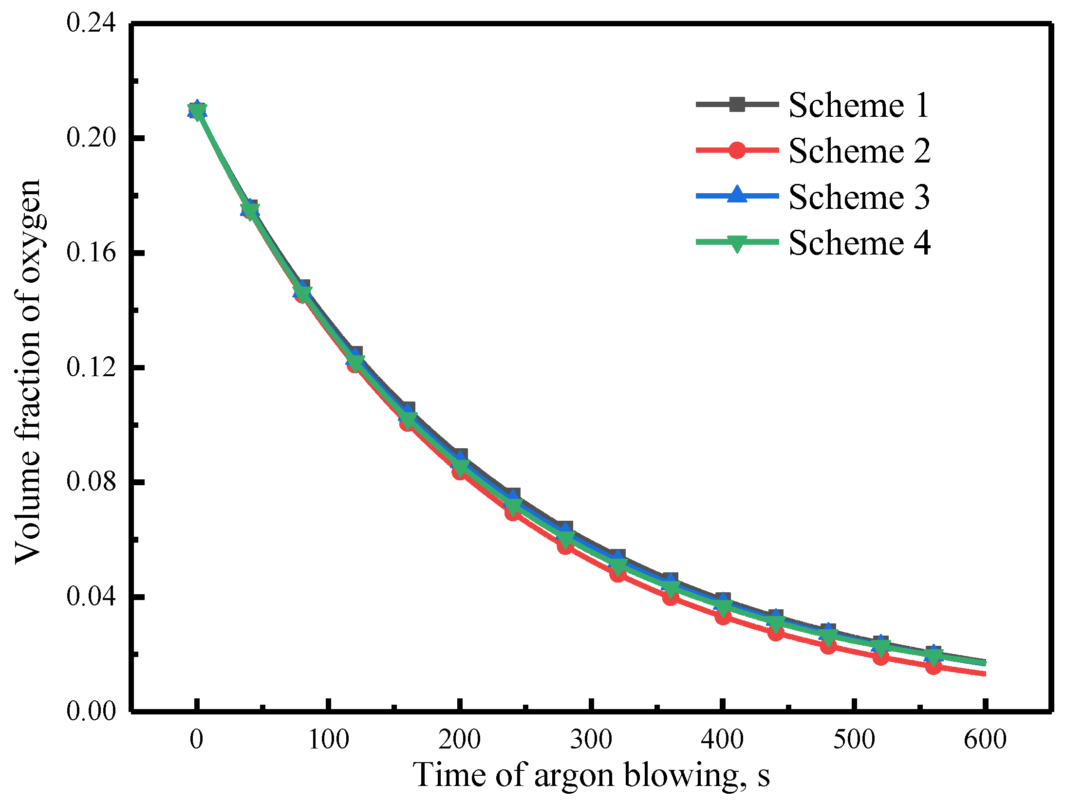
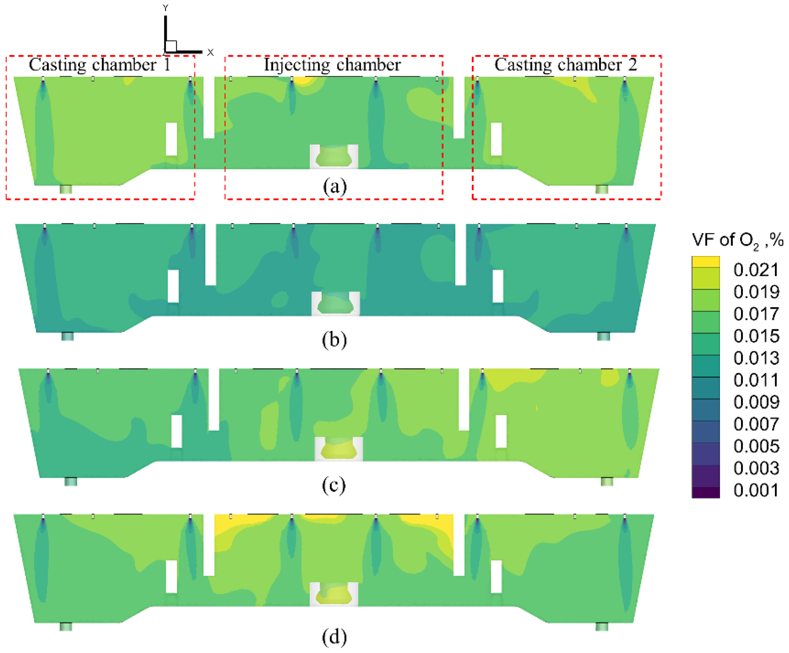
3.1.1. Calculation of the Sealing Scheme of Tundish Cover Holes during the Period of Empty Tundish

During practical production, there are about 5~10 min for blowing argon into tundish from the end of tundish baking to the start of casting. In order to improve the efficiency of protective casting and fully discharge oxygen, asbestos is usually used to seal some holes, such as the baking hole, injecting hole, or stopper hole. To determine the best sealing scheme during the period of empty tundish, three schemes were designed and described, as shown in Table 3. The average volume fractions of oxygen with argon flow rates of 200 Nm3/h for different schemes were calculated in 10 min. The variations of average argon volume fraction with respect to time for different schemes are shown in Figure 5. As shown in Figure 5, the difference in average oxygen volume fraction at 10 min between the Schemes 1, 3 and 4 is small, which is 0.0174, 0.0167, and 0.0170 respectively. Scheme 2, sealing the injecting hole and all baking holes, is the best, and its average oxygen volume fraction is 0.0132 at 10 min.
Figure 6 shows the contour of oxygen volume fraction at 10 min. For Scheme 1, sealing all stopper holes and all baking holes, the oxygen volume fraction in the casting chamber is higher than that in the injecting chamber. The dam and wall of tundish isolate the casting chamber and injecting chamber, which results in the oxygen in the casting chambers not being smoothly discharged and forming a dead zone. For Scheme 2, sealing the injecting hole and all baking holes, the oxygen volume fraction in the injecting chamber and casting chamber is relatively uniform, which indicates a better effect of discharging oxygen. For Scheme 3—sealing the injecting hole, stopper hole 2, and all baking holes—the oxygen volume fraction in casting chamber 1 is lower than that in chamber 2, which indicates the negative effects of discharging oxygen due to the long distance from casting chamber 2 to the outlet (stopper hole 1). As for Scheme 4, opening all holes, the oxygen content in the injecting chamber is higher than that in the casting chamber due to the stronger backflow of air. Overall, Scheme 2 is the best and used for the analysis of argon flow rate.

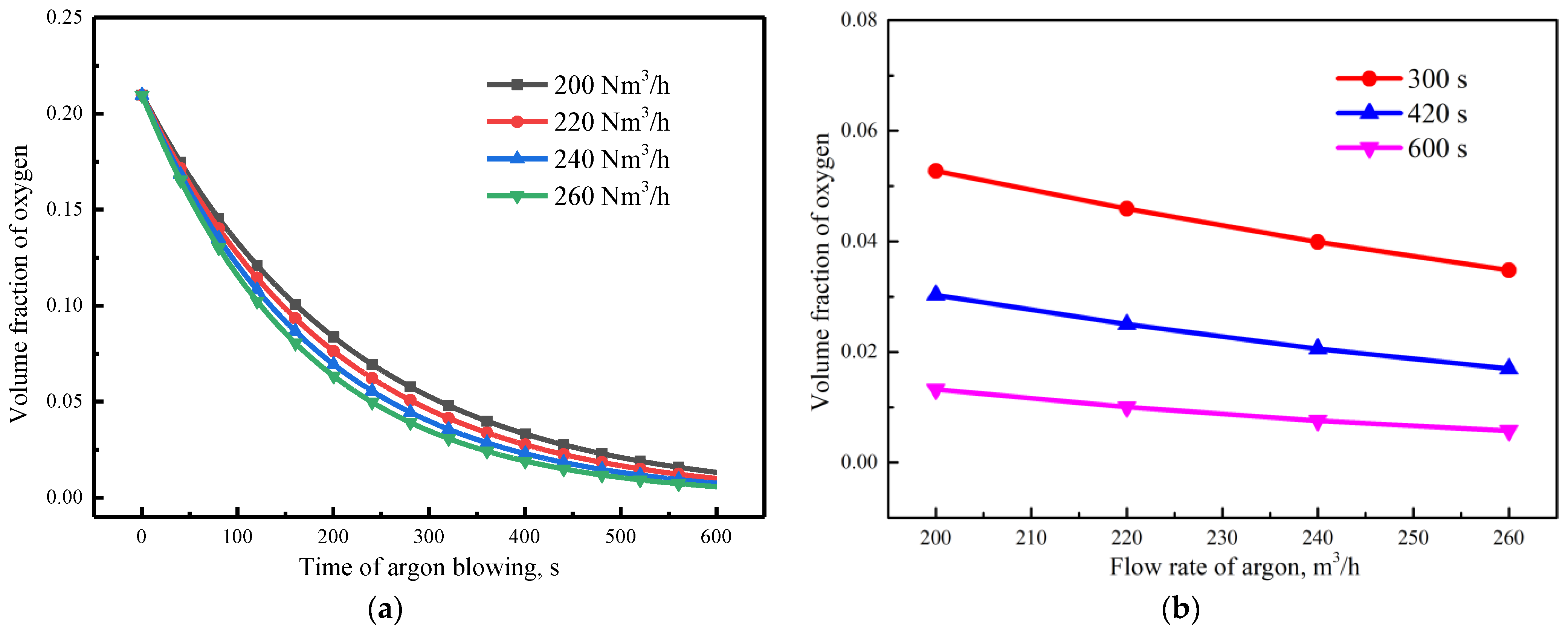
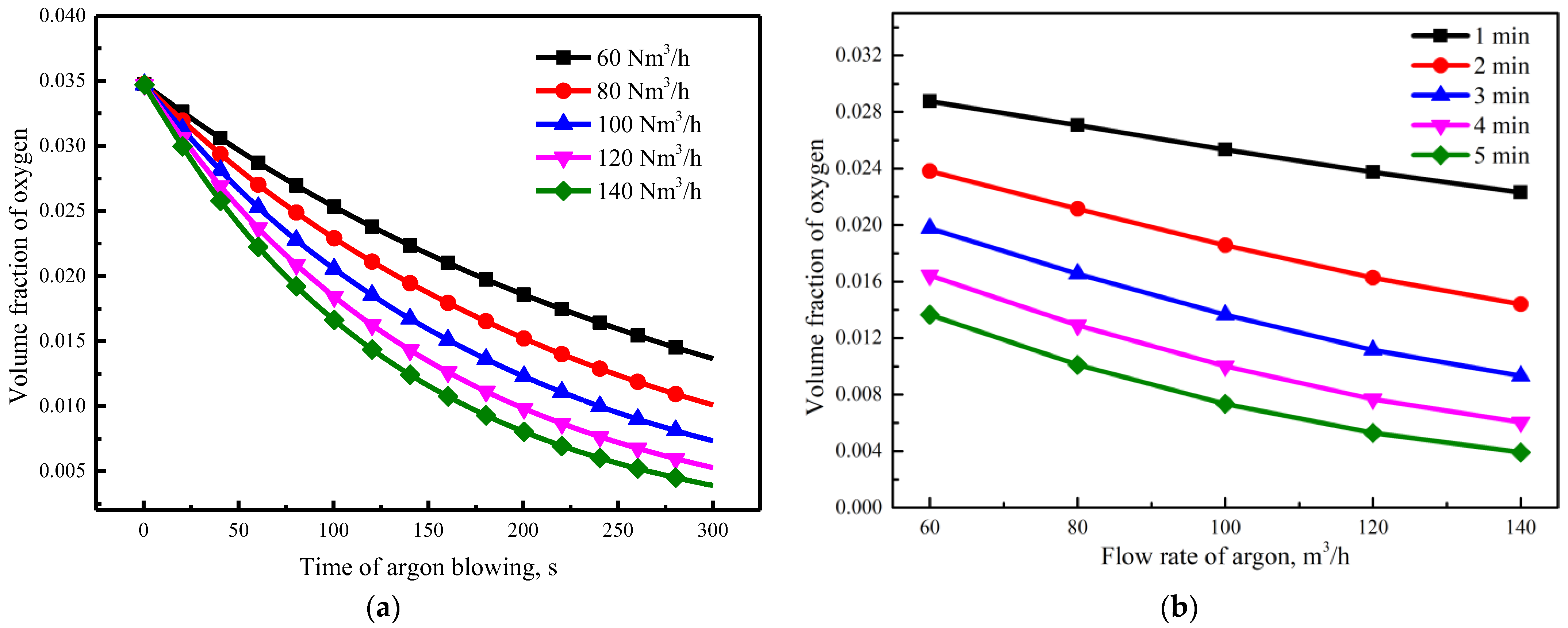
3.1.2. Calculation of Argon Flow Rate during a Period of Empty Tundish

Figure 7a shows the variation of average oxygen volume fraction with time under different argon flow rates. The volume fraction of oxygen shows similar tendencies for different argon flow rates, but the increase in argon flow rate accelerates the reduction of oxygen volume fraction, which shows that increasing the argon flow rate is conducive to discharging oxygen in tundish. Figure 7b shows the effect of argon flow rate on average volume fraction of oxygen at different times. The average volume fraction of oxygen linearly decreases with the increase in argon flow rate. It can be reduced to 1% after 10 min when the argon flow rate is 220 Nm3/h, which indicates that the argon flow rate should be greater than 220 Nm3/h to ensure that the remaining volume fraction of oxygen is less than 1% and achieves a better protective casting effect during a period of empty tundish.

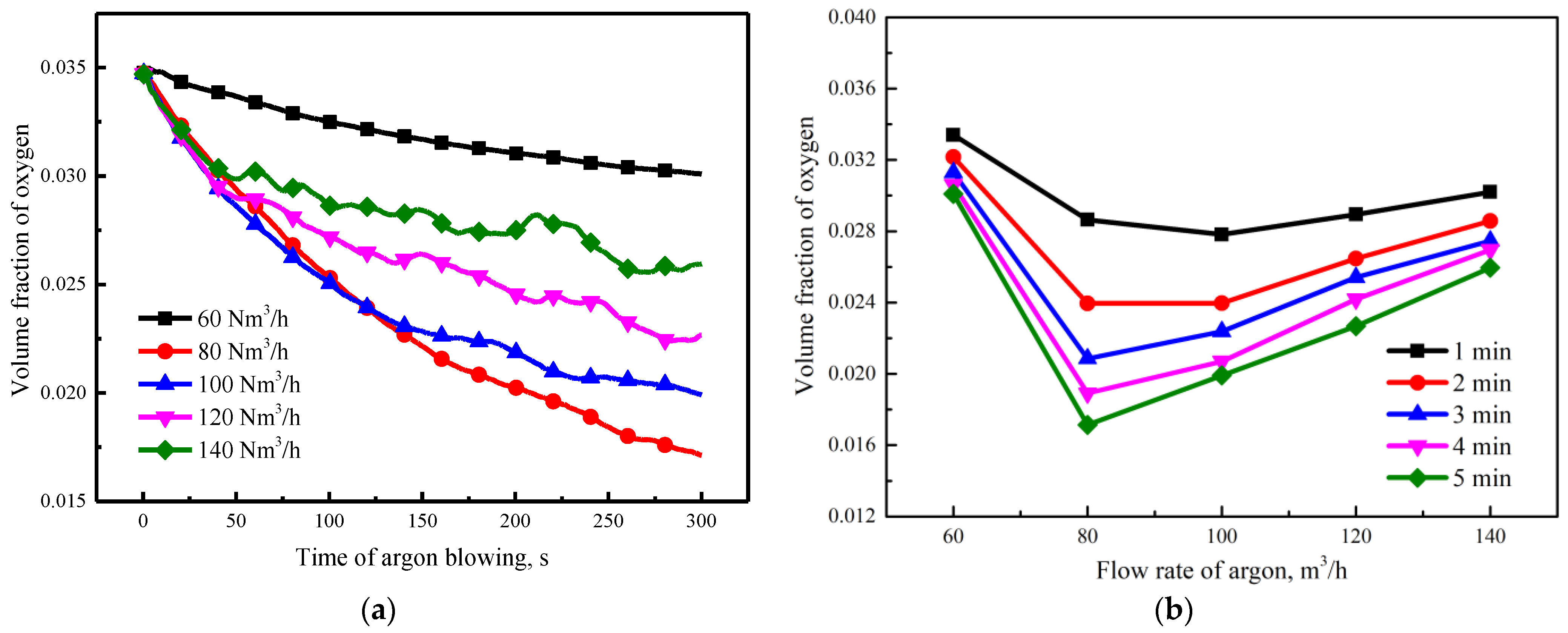
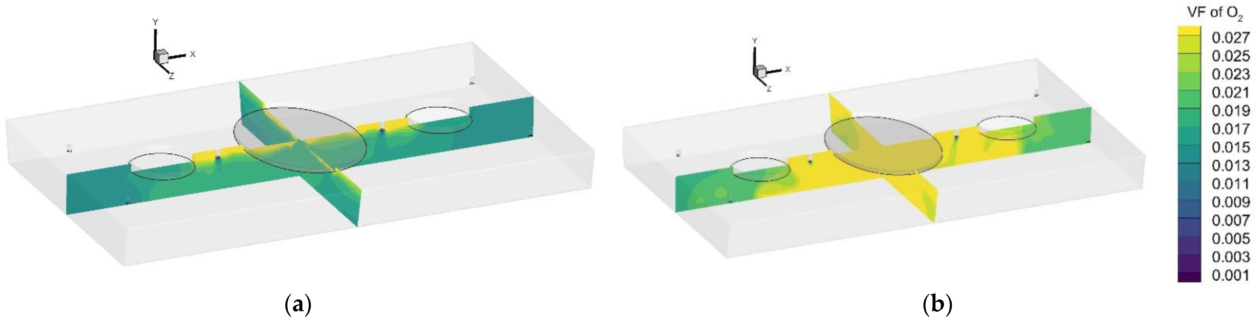
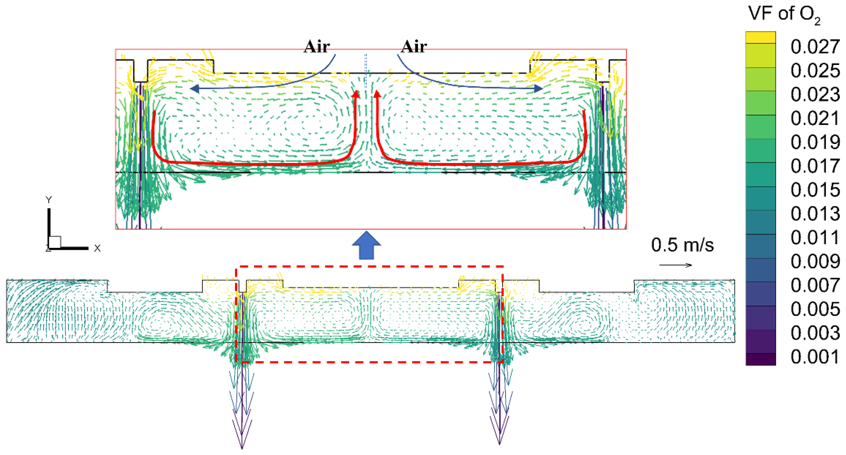
3.1.3. Calculation of Argon Flow Rate during a Period of Normal Casting

During a period of normal casting, the injecting chamber and casting chambers are isolated into independent chambers by molten steel. There is no gas exchange between those independent chambers. Compared with a period of empty tundish, the holding capacity of gas in the tundish largely decreases, and the argon flow rate should be adjusted during a period of normal casting. In order to determine the optimal argon flow rate, the variation of average oxygen volume fraction in an isolated injecting chamber and casting chamber was investigated, respectively. During the calculation, the oxygen volume fraction of Scheme 2 with an argon flow rate of 260 Nm3/h at 5 min was taken as the initial condition. During a period of normal casting, the baking holes are usually sealed except for the sampling operation, and the stopper holes and injecting hole remain open.
Figure 8a shows the variation of oxygen volume fraction with time in the isolated injecting chamber. The volume fraction of oxygen decreases with increasing argon blowing time, but the downtrend shows a tendency of increasing first and then decreasing with the increase in argon flow rate. The oxygen volume fractions after argon blowing for 5 min are 0.03, 0.0171, and 0.0259 when the argon flow rates are 60 Nm3/h, 80 Nm3/h, and 120 Nm3/h, respectively. Figure 8b shows the oxygen volume fraction at a given time under different argon flow rates. At a fixed time, the oxygen volume fraction first decreases and then increases with increase in argon flow rate, showing a minimum value at an argon flow rate of 80 Nm3/h.
In order to explain this phenomenon, the contours of oxygen volume fraction and velocity vector at z = 0 m section are abstracted and shown in Figure 9 and Figure 10. As shown in Figure 9, when the argon flow rate is 80 Nm3/h, the oxygen volume fraction in the injecting chamber is uniform, except the region near the injecting holes, where it is slightly higher than that in the other region. With the argon flow rate increasing to 140 Nm3/h, the region of oxygen volume fraction of more than 0.027 in injecting chamber significantly increases, and even extends into the vicinity of baking holes. This phenomenon can be explained by the velocity vector, as shown in Figure 10. Argon jets into the injecting chamber by the argon pipe installed on both sides of the injecting hole. After the argon jet impacts the molten steel, two horizontal streams occur and collide at the center of the injecting hole, and then discharge from the injecting hole. With the discharge in argon, a large amount of air is drawn into the injecting chamber and results in an increase in oxygen volume fraction. The phenomenon of air entrainment increases with the increase in argon flow rate. Therefore, the best argon flow rate in the injecting chamber is 80 Nm3/h.
The variation behavior of oxygen volume fraction in the isolated casting chamber was also investigated and is shown in Figure 11. The volume fraction of oxygen in the isolated casting chamber continuously decreases with the increase in argon blowing time, and the downtrend shows a positive correlation with argon flow rate. Figure 11b shows the oxygen volume fraction at a given time under different argon flow rates. The oxygen volume fraction decreases with the increase in argon flow rate at a given time and achieves 1% at 5 min when the argon flow rate is 80 Nm3/h, which indicates the argon flow rate in the isolated casting room should be greater than 80 Nm3/h. However, combined with the variation behavior of oxygen volume fraction in an isolated injecting chamber, the argon flow rate should be kept as 80 Nm3/h for the period of normal casting.

3.2. Industrial Application

In order to evaluate the process effect of ABTC, plant trials of two consecutive tundishes for continuous casting were conducted, and each tundish was used for six ladles. The first tundish with ABTC, under Scheme 2, was taken as the trial group, and the second tundish without ABTC was taken as the control group. The process parameters of ABTC and continuous casting are listed in Table 4.
During trials, steel samples at the end of RH and in the tundish for each ladle were taken, and the contents of nitrogen, titanium, and aluminum in the steel samples were measured and are listed in Table 5. By applying ABTC, the average nitrogen content of steel samples in tundish decreases from 22 × 10−6 to 16 × 10−6, and the average increased nitrogen content (△w[N]) from the end of RH to tundish decreases by 90% from 10 × 10−6 to 1 × 10⁻⁶. The average loss of titanium and aluminum decreases by 12.7% from 63 × 10−6 to 55 × 10−6 and 7.1% from 70 × 10−6 to 55 × 10−6, respectively. In general, the ABTC process is conducive to decreasing the increased nitrogen content of molten steel in tundish and the loss of titanium and aluminum. Therefore, the protective casting effect could be significantly improved by applying ABTC.

4. Conclusions

In this study, the feasibility and application effect of ABTC during a continuous casting period were investigated and evaluated through simulations and plant trials. The following conclusions can be drawn:
(1)
The process of ABTC shows a great protective casting effect in avoiding increasing nitrogen and losing titanium and aluminum. As for the steel grade of M3A35, the average increment of nitrogen content (△w[N]) decreases by 90%, and the average losses of titanium △w[Ti] and aluminum △w[Al] decrease by 12.7% and 7.1%, respectively.
(2)
During ABTC, the injecting hole and baking holes should be sealed, and the argon flow rate should be ≥220 Nm3/h to obtain better protective effects during a period of empty tundish.
(3)
During a period of normal casting, the rational argon flow rate is 80 Nm3/h due to the strong air entrainment in the isolated injecting chamber.

Author Contributions

Conceptualization, Y.L. and X.Y.; Data curation, C.W.; Investigation, Y.L.; Methodology, X.X.; Software, Y.L.; Supervision, X.M.; Validation, J.C.; Writing—original draft, Y.L.; Writing—review and editing, C.W., X.X. and L.C. All authors have read and agreed to the published version of the manuscript.

Funding

This research is supported by the Pangang Group Research Institute Co., Ltd.

Institutional Review Board Statement

Not applicable.

Informed Consent Statement

Not applicable.

Data Availability Statement

Not applicable.

Conflicts of Interest

The authors declare no conflict of interest that are relevant to the content of this article.

References

  1. Chu, J.; Bao, Y. Study on the relationship between vacuum denitrification and manganese evaporation behaviours of manganese steel melts. Vacuum 2021, 192, 110420. [Google Scholar] [CrossRef]
  2. Kawakami, K.; Taniguchi, T.; Nakashima, K. Generation Mechanisms of Non-metallic Inclusions in High-cleanliness Steel. Tetsu--Hagane 2007, 93, 743–752. [Google Scholar] [CrossRef] [Green Version]
  3. Ling, H.; Zhang, L.; Liu, C. Effect of snorkel shape on the fluid flow during RH degassing process: Mathematical modelling. Ironmak Steelmak. 2018, 45, 145–156. [Google Scholar] [CrossRef]
  4. Ling, H.T.; Zhang, L.F. Investigation on the Fluid Flow and Decarburization Process in the RH Process. Metall. Mater. Trans. B 2018, 49, 2709–2721. [Google Scholar] [CrossRef]
  5. Cao, Q.; Nastac, L. Numerical modelling of the transport and removal of inclusions in an industrial gas-stirred ladle. Ironmak Steelmak. 2018, 45, 984–991. [Google Scholar] [CrossRef]
  6. Liu, Y.; Ersson, M.; Liu, H.; Jonsson, P.G.; Gan, Y. Reply to the Discussion on “A Review of Physical and Numerical Approaches for the Study of Gas Stirring in Ladle Metallurgy”. Metall. Mater. Trans. B 2020, 51, 1847–1850. [Google Scholar] [CrossRef]
  7. Jardon-Perez, L.E.; Gonzalez-Rivera, C.; Ramirez-Argaez, M.A.; Dutta, A. Numerical Modeling of Equal and Differentiated Gas Injection in Ladles: Effect on Mixing Time and Slag Eye. Processes 2020, 8, 917. [Google Scholar] [CrossRef]
  8. Liu, W.; Lee, J.; Guo, X.; Silaen, A.K.; Zhou, C.Q. Argon Bubble Coalescence and Breakup in a Steel Ladle with Bottom Plugs. Steel Res. Int. 2019, 90, 1800396. [Google Scholar] [CrossRef]
  9. Li, L.; Liu, Z.; Cao, M.; Li, B. Large Eddy Simulation of Bubbly Flow and Slag Layer Behavior in Ladle with Discrete Phase Model (DPM)–Volume of Fluid (VOF) Coupled Model. JOM 2015, 67, 1459–1467. [Google Scholar] [CrossRef]
  10. Li, Y.; Deng, A.Y.; Li, H.; Yang, B.; Wang, E.G. Numerical Study on Flow, Temperature, and Concentration Distribution Features of Combined Gas and Bottom-Electromagnetic Stirring in a Ladle. Metals 2018, 8, 19. [Google Scholar] [CrossRef]
  11. Chen, S.; Lei, H.; Wang, M.; Yang, B.; Dou, W.; Chang, L.; Zhang, H. Ar-CO-liquid steel flow with decarburization chemical reaction in single snorkel refining furnace. Int. J. Heat Mass Tran. 2020, 146, 118857. [Google Scholar] [CrossRef]
  12. Ling, H.; Xu, R.; Wang, H.; Chang, L.; Qiu, S. Multiphase Flow Behavior in a Single-Strand Continuous Casting Tundish during Ladle Change. ISIJ Int. 2020, 60, 499–508. [Google Scholar] [CrossRef] [Green Version]
  13. Cwudzinski, A. Physical and mathematical modeling of bubbles plume behaviour in one strand tundish. Metall. Res. Technol. 2018, 115, 101. [Google Scholar] [CrossRef]
  14. Chatterjee, S.; Chattopadhyay, K. Physical Modeling of Slag ‘Eye’ in an Inert Gas-Shrouded Tundish Using Dimensional Analysis. Metall. Mater. Trans. B 2016, 47, 508–521. [Google Scholar] [CrossRef]
  15. Yang, W.; Luo, Z.; Gu, Y.; Liu, Z.; Zou, Z. Simulation of bubbles behavior in steel continuous casting mold using an Euler-Lagrange framework with modified bubble coalescence and breakup models. Powder Technol. 2020, 361, 769–781. [Google Scholar] [CrossRef]
  16. Wang, Y.; Fang, Q.; Zhang, H.; Zhou, J.; Liu, C.; Ni, H. Effect of argon blowing rate on multiphase flow and initial solidification in a slab mold. Metall. Mater. Trans. B 2020, 51, 1088–1100. [Google Scholar] [CrossRef]
  17. Zhang, H.; Fang, Q.; Xiao, T.P.; Ni, H.W.; Liu, C.S. Optimization of the flow in a slab mold with argon blowing by divergent bifurcated SEN. ISIJ Int. 2019, 59, 86–92. [Google Scholar] [CrossRef] [Green Version]
  18. Yang, W.D.; Luo, Z.G.; Lai, Q.R.; Zou, Z.S. Study on bubble coalescence and bouncing behaviors upon off-center collision in quiescent water. Exp. Therm. Fluid Sci. 2019, 104, 199–208. [Google Scholar] [CrossRef]
  19. Feng, W. Reoxidation Phenomenon and Inhibition Mechanism of Aluminum-Deoxidized Steel in Tangsteel; University of Science and Technology Beijing: Beijing, China, 2019. [Google Scholar]
  20. Story, S.R.; Goldsmith, G.E.; Fruehan, R.J.; Casuccio, G.S.; Potter, M.S.; Wlliams, D.M. A study of casting issues using rapid inclusion identification and analysis. Iron Steel Technol. 2006, 3, 52–61. [Google Scholar]
  21. Sun, Y.; Cai, K.; Zhao, C. Effect of transient casting operation on cleanliness of continuously cast strands. Iron Steel 2008, 43, 22–25. [Google Scholar] [CrossRef]
  22. Gao, J.; Yan, S.; Ding, Z. Analysis on surface defects of deep-drawing piece of steel DC04-LQQ for filter and process control. Spec. Steel 2017, 38, 27–31. [Google Scholar]
  23. Launder, B.; Spalding, D.B. The numerical computation of turbulent flows. Comput. Method. Appl. Mech. 1974, 3, 269–289. [Google Scholar] [CrossRef]
Figure 1. Structure diagram of a two-strand slab tundish.
Metals 12 01801 g001
Figure 2. Arrangement of the argon blowing pipe on the two-strand slab tundish cover (mm).
Metals 12 01801 g002
Figure 3. Mesh for empty tundish (a), isolated casting chamber (b), and isolated injecting chamber (c) (mm).
Metals 12 01801 g003
Figure 4. Snapshot of the industrial test (a) and comparison of the industrial test data and numerical calculation (b).
Metals 12 01801 g004
Figure 5. Variation of oxygen volume fraction in tundish for different schemes.
Metals 12 01801 g005
Figure 6. Contour of oxygen volume fraction at z = 0 m section, (a) for Scheme 1, (b) Scheme 2, (c) Scheme 3, (d) and Scheme 4.
Metals 12 01801 g006
Figure 7. Variation of volume fraction of oxygen with time for different argon flow rates (a), and effect of argon flow rate on the volume fraction of oxygen at different times (b).
Metals 12 01801 g007
Figure 8. Variation of oxygen volume fraction with time for different argon flow rates (a) and effect of argon flow rate on volume fraction of oxygen for different times (b) in an isolated injecting chamber.
Metals 12 01801 g008
Figure 9. Contour of argon volume fraction at the z = 0 m section for different argon flow rates in the injecting chamber: (a) 80 Nm3/h, and (b) 140 Nm3/h.
Metals 12 01801 g009
Figure 10. Vector of argon velocity at z = 0 m section in the injecting chamber.
Metals 12 01801 g010
Figure 11. Variation of oxygen volume fraction with time for different argon flow rate (a), and effect of argon flow rate on volume fraction of oxygen at different times (b) in an isolated casting chamber.
Metals 12 01801 g011
Table 1. Parameters of tundish and the casting process.
ItemValue
Slab section size, mm × mm230 × 1300
Casting speed, m·min−10.9–1.2
Depth of molten steel during normal casting period, mm1000
Diameter of baking hole, mm380, 360
Diameter of argon pipe, mm30
Distance between molten slag surface and tundish cover, mm250
Density of argon at 288 K, kg·m−31.6228
Density of air at 288 K, kg·m−31.225
Viscosity of argon, kg·m−1·s−12.125 × 10⁻⁵
Viscosity of air, kg·m−1·s−11.789 × 10⁻⁵
Mass fraction of oxygen in air0.21
Mass diffusivity of mixture, m2·s−12.88 × 10⁻⁵
Total flow rate of argon blowing, Nm3·h−160, 100, 120, 140, 200, 220, 240, 260
Table 2. Error statistics of different meshes.
MeshM1M2M3M4
Total cell number192,236325,618508,483612,348
Total node number998,0501,878,1662,932,9323,532,026
Average volume faction of oxygen0.048460.047650.045910.04511
δoxygen = |VFoxygen-iVFoxygen-4|/VFoxygen-40.07430.05630.0179
Table 3. Sealing schemes of tundish cover holes.
Scheme No.Seal of Tundish Cover Hole
1Stopper hole 1–2, baking hole 1–4
2Injecting hole, baking hole 1–4
3Injecting hole, stopper hole 2, baking hole 1–4
4None
Table 4. Process parameters of argon blowing tundish cover and continuous casting.
ItemValue
ABTC during a period of empty tundishArgon flow rate: 220 Nm3/h; Time of argon blowing: 3 min
ABTC during a period of normal castingArgon flow rate: 100 Nm3/h; Time of argon blowing: all the other time
Steel gradeM3A35
Steel composition, wt%C ≤ 0.002, Si ≤ 0.005, Mn: 0.05~0.08, Ti: 0.065~0.085, Al: 0.02~0.035, Cr ≤ 0.05, Ni ≤ 0.05, Mo ≤ 0.01
Casting speed, m/min1.12
Section size of slab, mm × mm1300 × 230
Table 5. Mass fractions of nitrogen, titanium, and aluminum of steel samples at the end of RH and in tundish.
Heat No.Trial Group with ABTC, ×10−6Control Group without ABTC, ×10−6
End of RH, wTundish, wIncrement, △wEnd of RH, wTundish, wIncrement, △w
[N][Ti][Al][N][Ti][Al][N][Ti][Al][N][Ti][Al][N][Ti][Al][N][Ti][Al]
115760434157103500−50−8416750448177003601−50−88
212820427167603804−60−47168004622875042012−50−42
314800422137103100−90−11216820466167003600−120−106
419760395187303400−30−5507904742376045023−30−24
516770407177203601−50−4724810470227303900−80−80
615820436177703902−50−4608004182775034027−50−78
Average1578842016733355155651279545622732387106370
Publisher’s Note: MDPI stays neutral with regard to jurisdictional claims in published maps and institutional affiliations.

