
Synthesis of Complex Concentrated Nanoparticles by Ultrasonic Spray Pyrolysis and Lyophilisation

 ,
, 
 ,
,  ,
,
Abstract
:1. Introduction
2. Materials and Methods
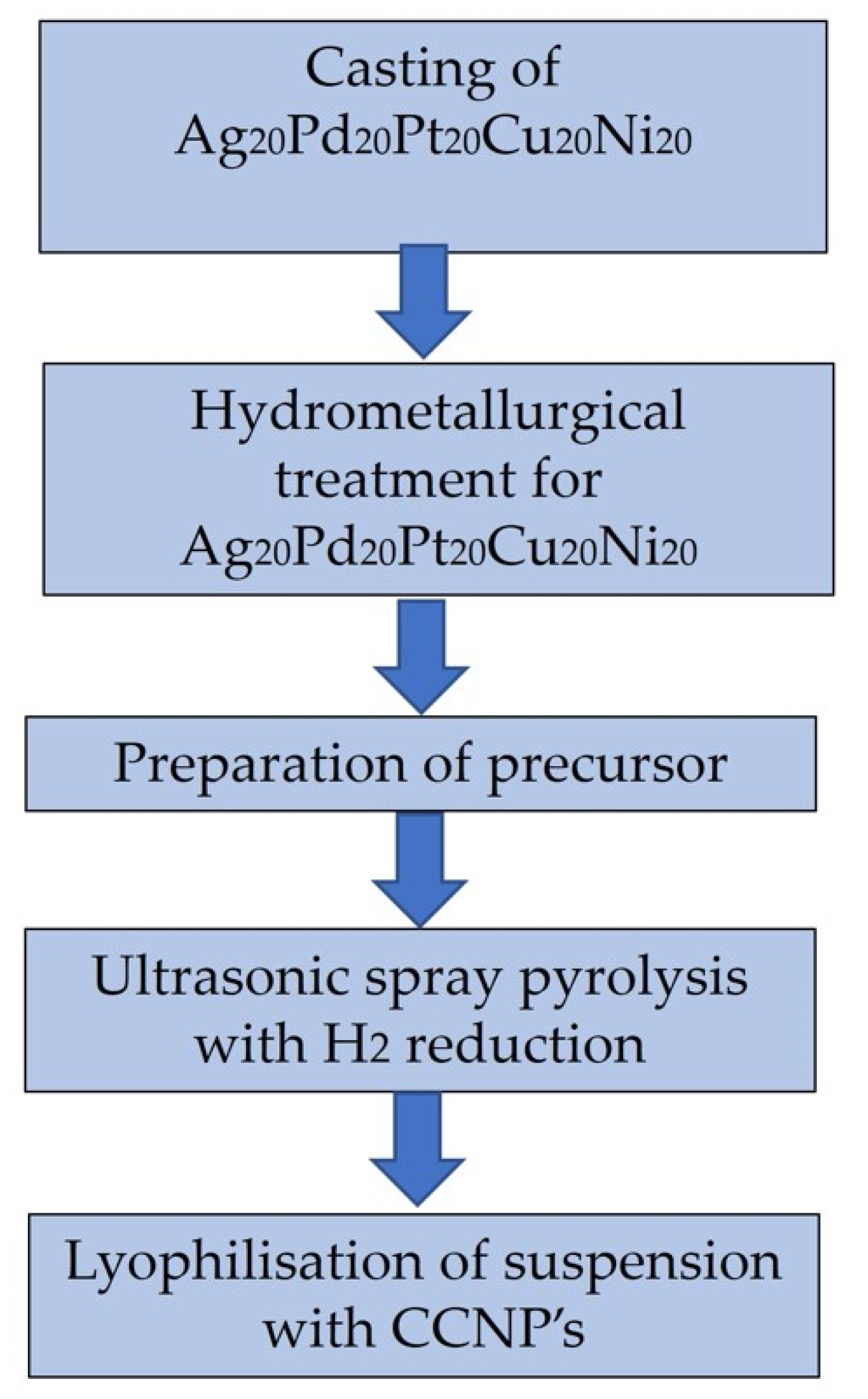
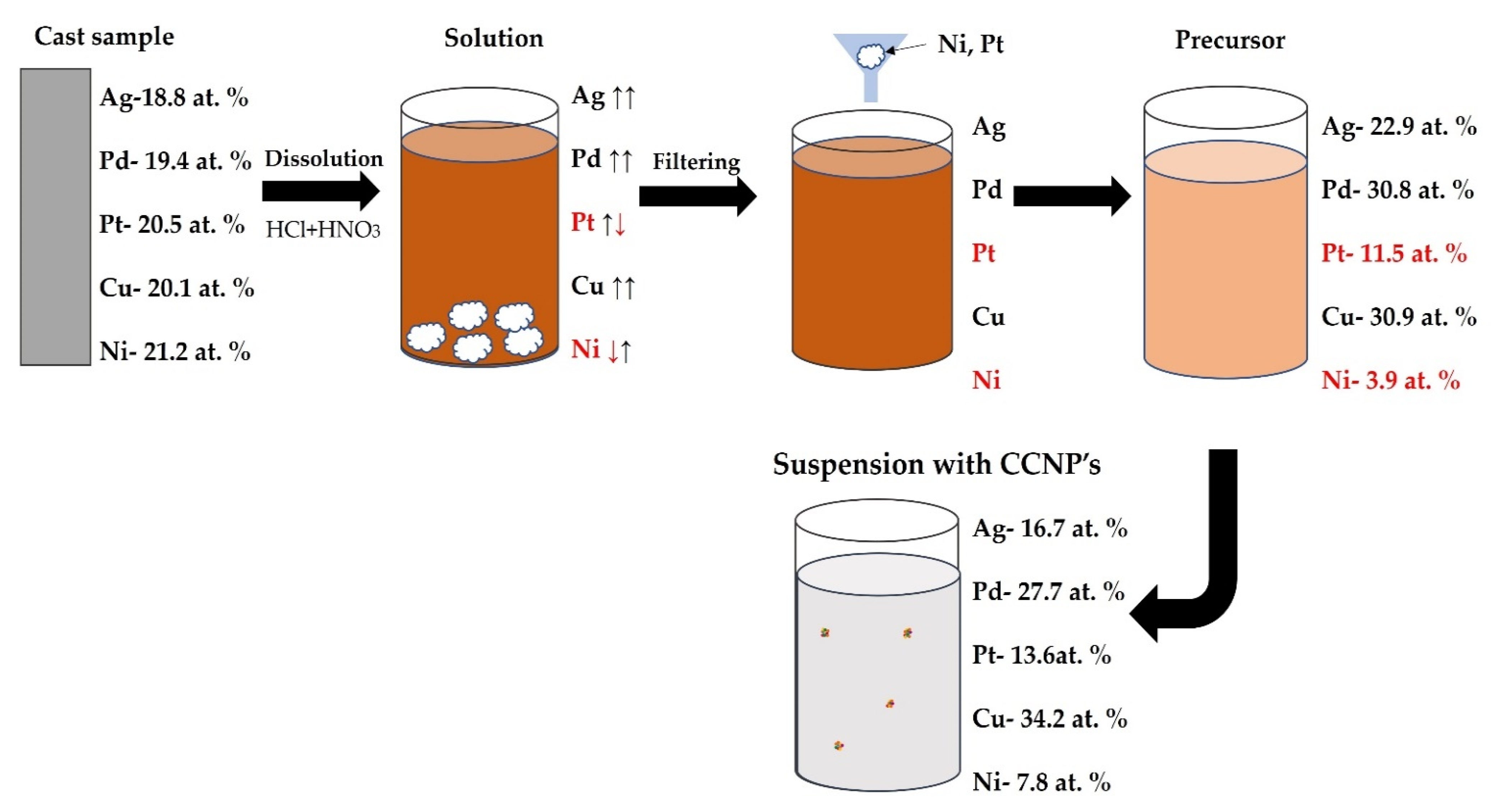
2.1. Casting of Ag20Pt20Pd20Cu20Ni20
2.2. Hydrometallurgical Treatment
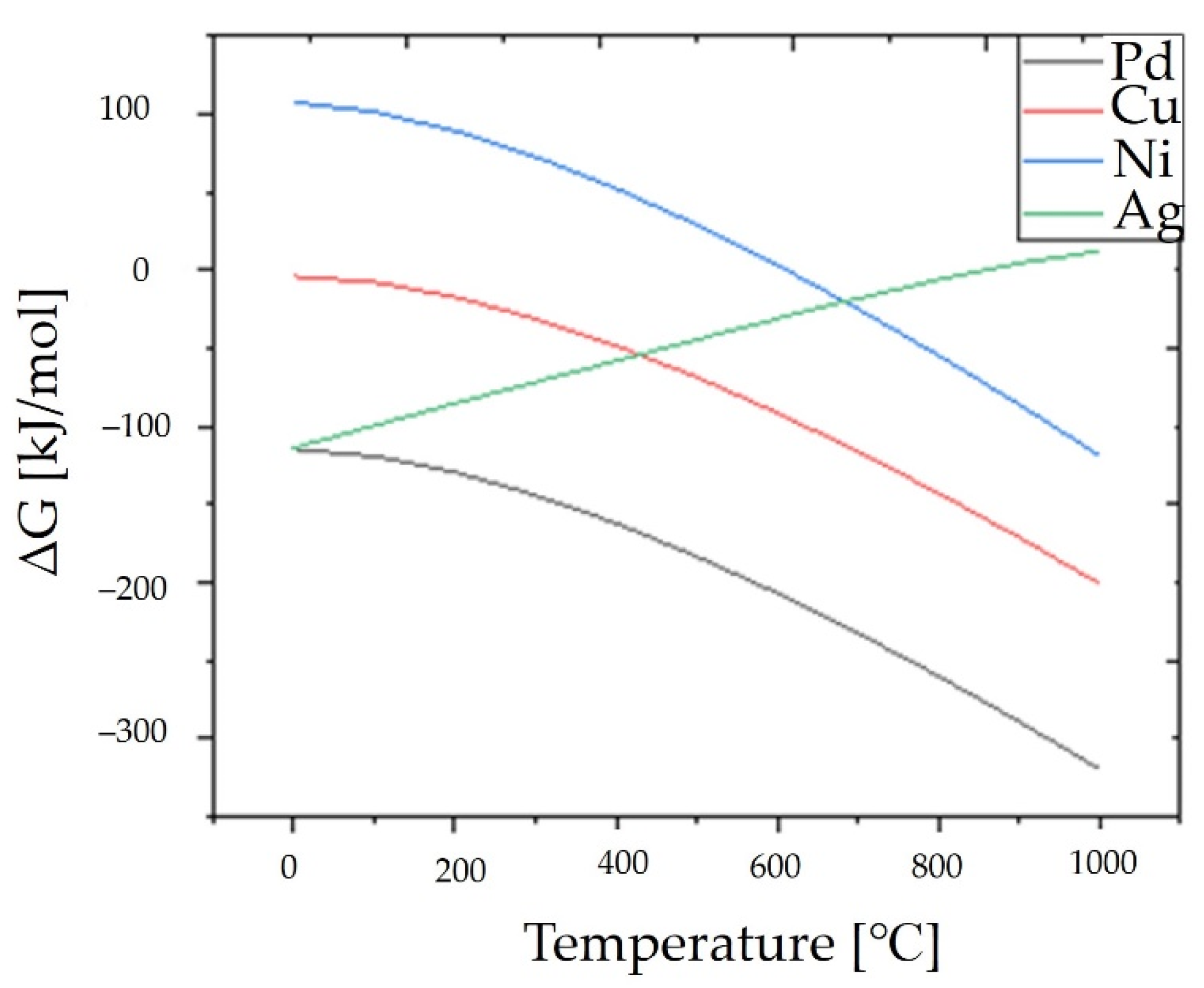
2.3. Thermochemical Analysis of Hydrogen Reduction
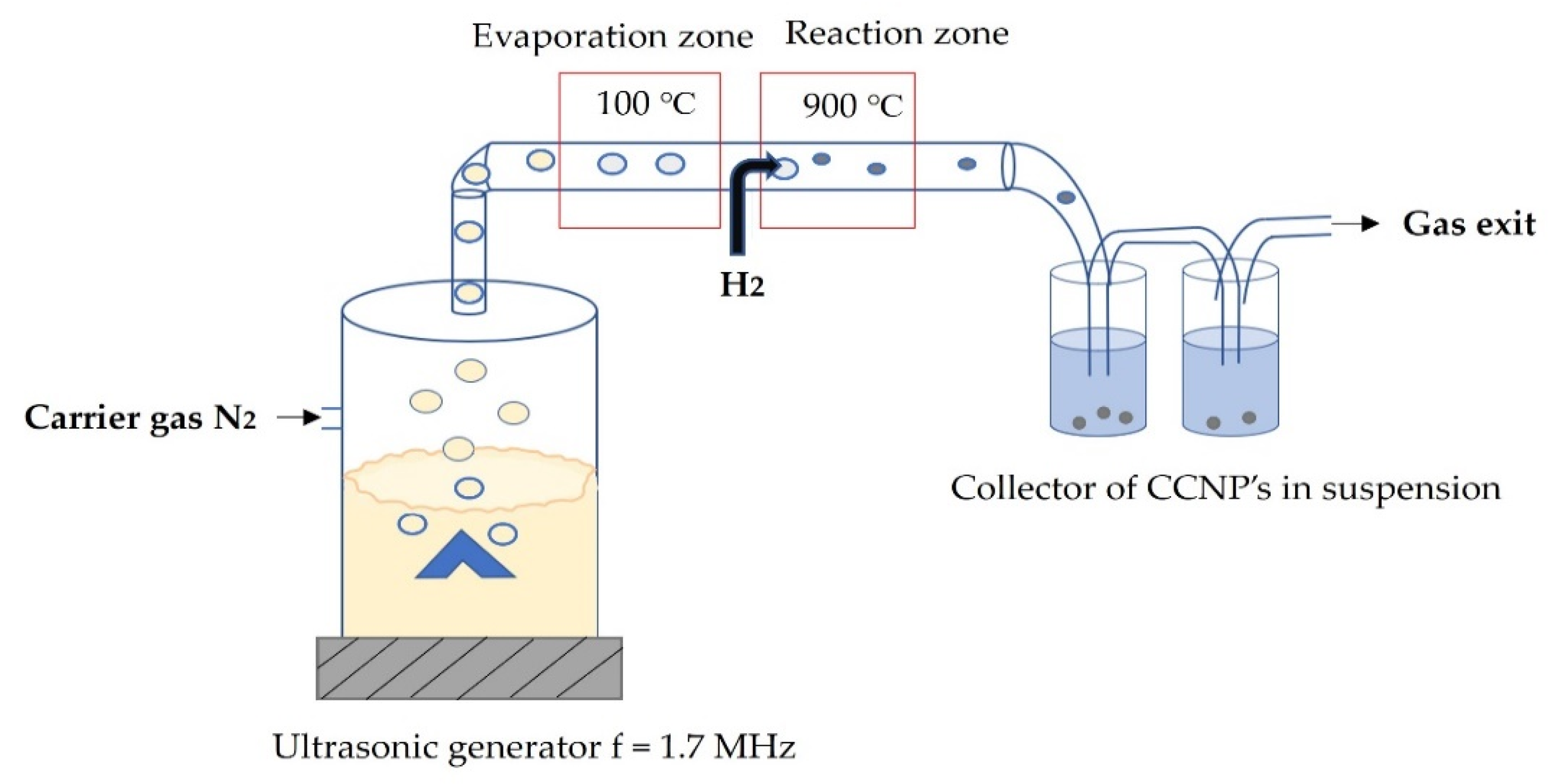
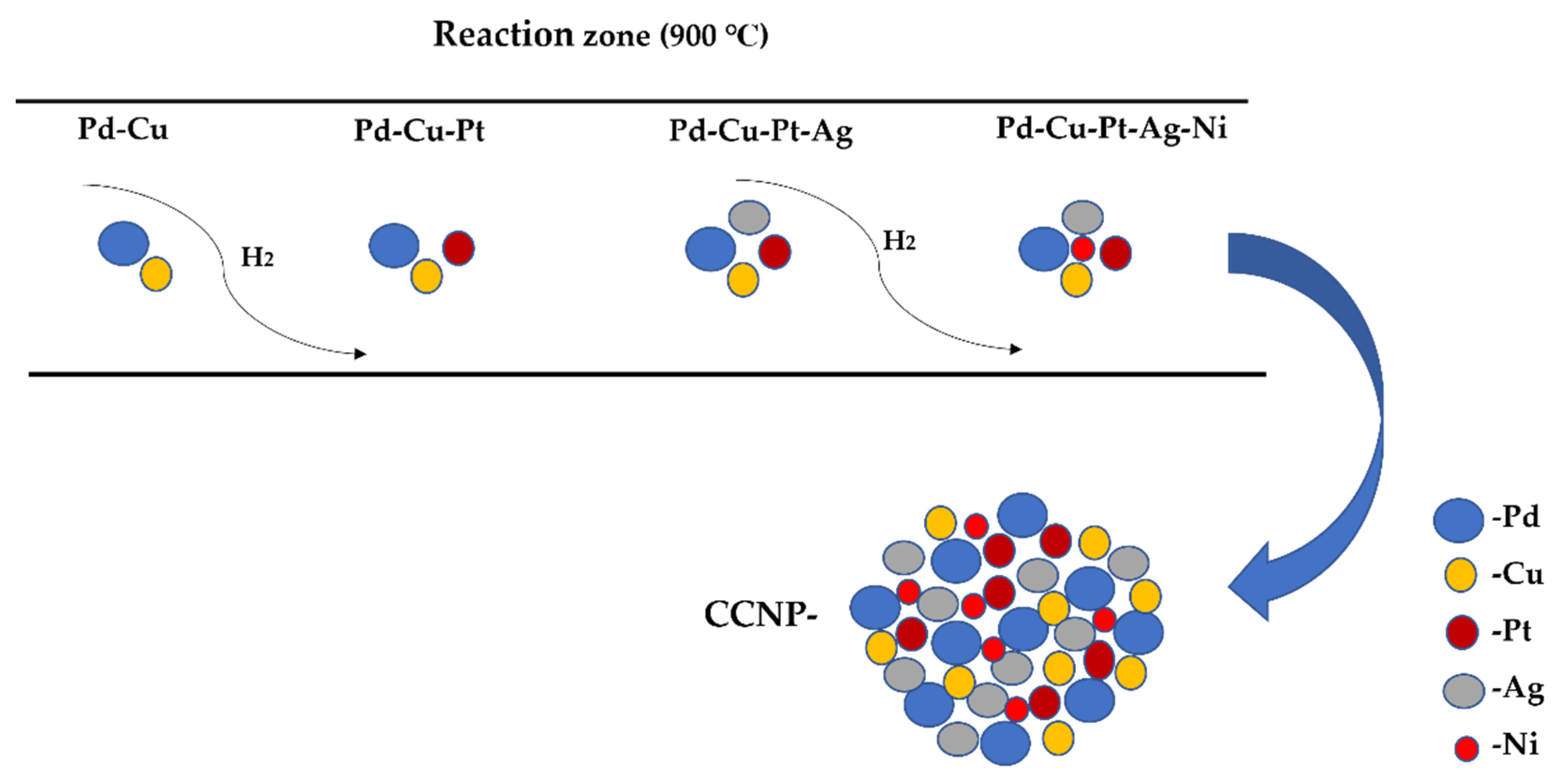
2.4. USP Synthesis
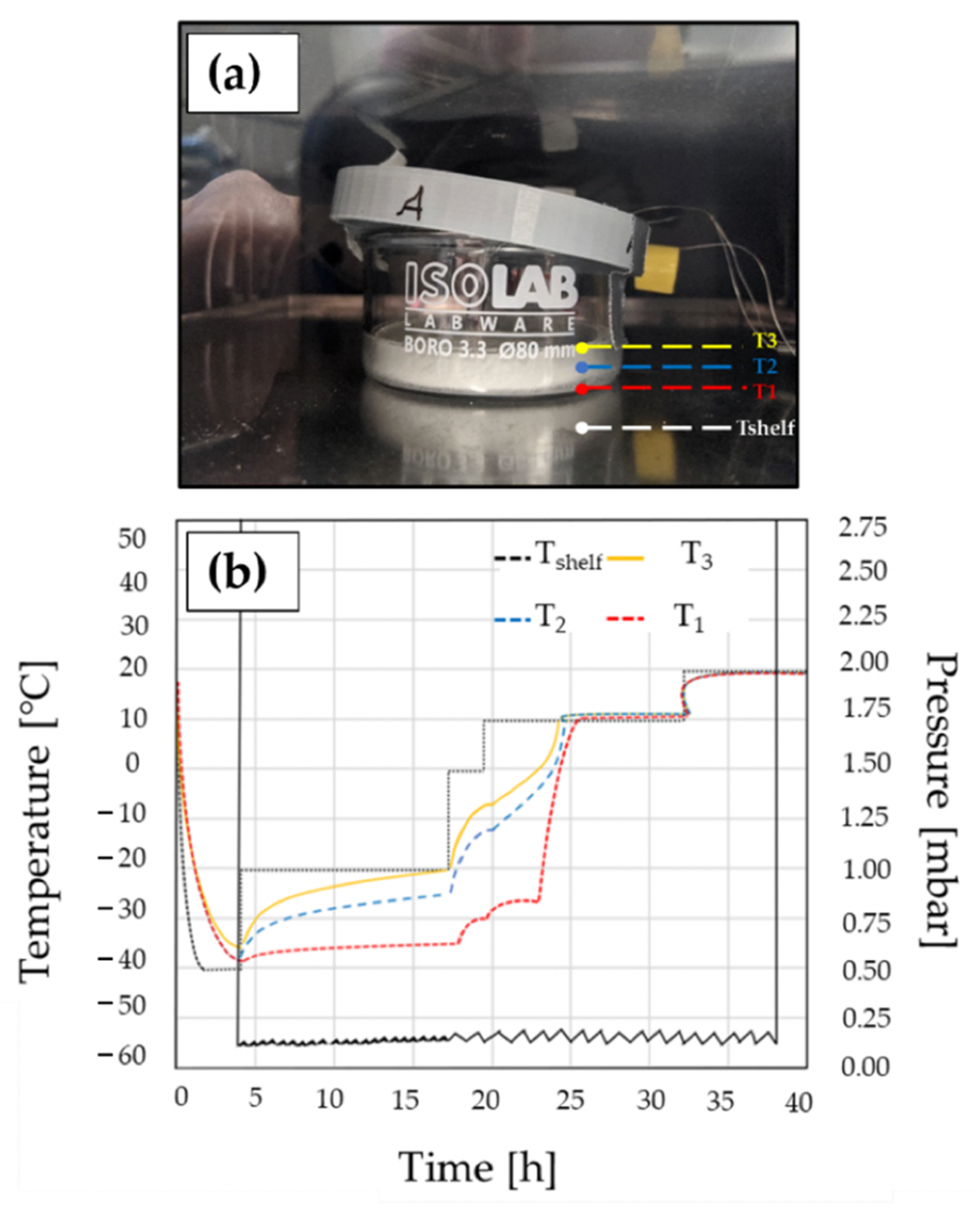
2.5. Lyophilisation
3. Characterisation
3.1. XRF—X-ray Fluorescence Spectroscopy of the Cast Ag20Pd20Pt20Cu20Ni20 Alloy
3.2. ICP–OES—Inductively Coupled Plasma–Optical Emission Spectrometry
3.2.1. Precursor
3.2.2. Suspension with CCNPs
3.3. DLS Method and Zeta Potential Measurements
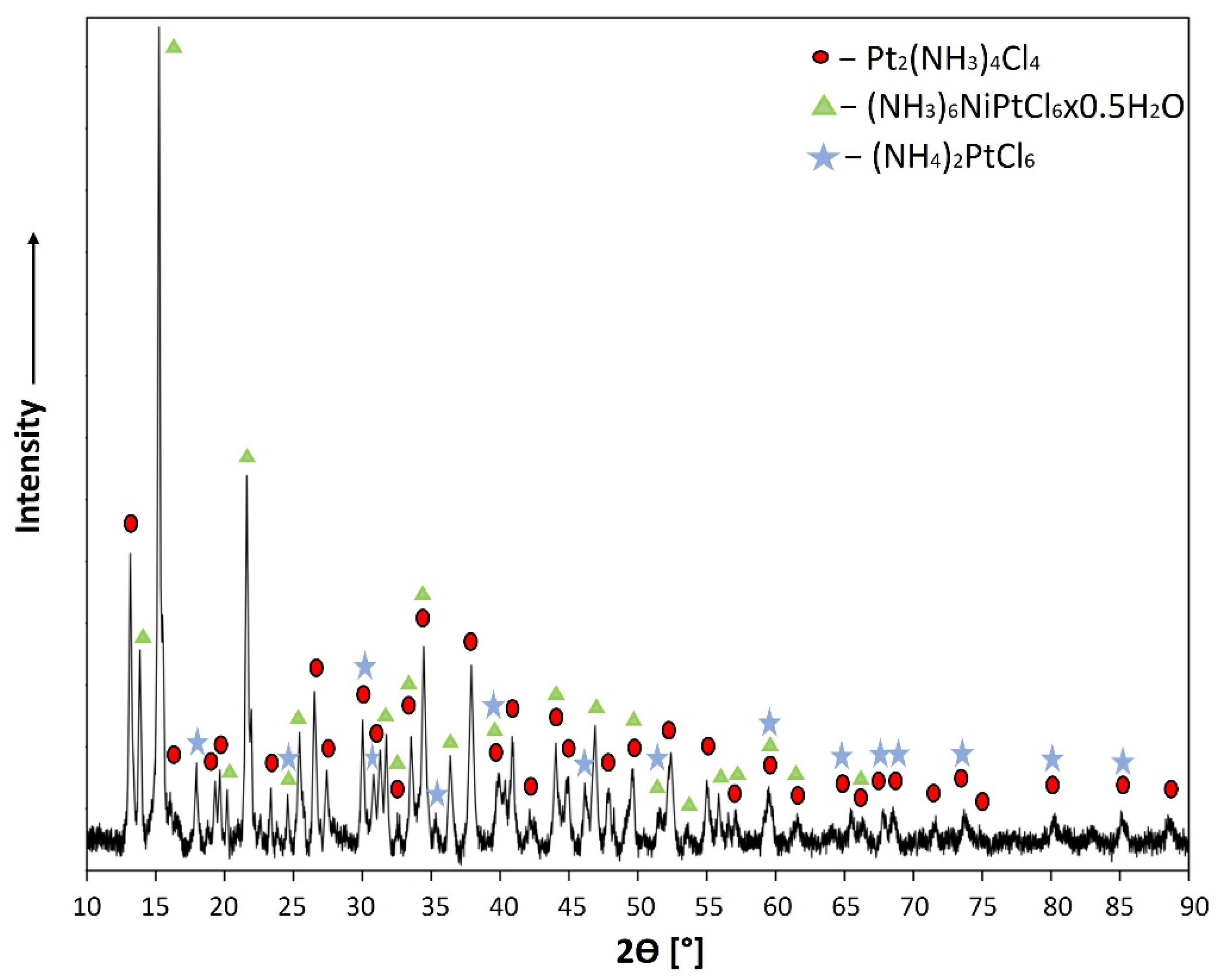
3.4. XRD Analysis of Formed Precipitate
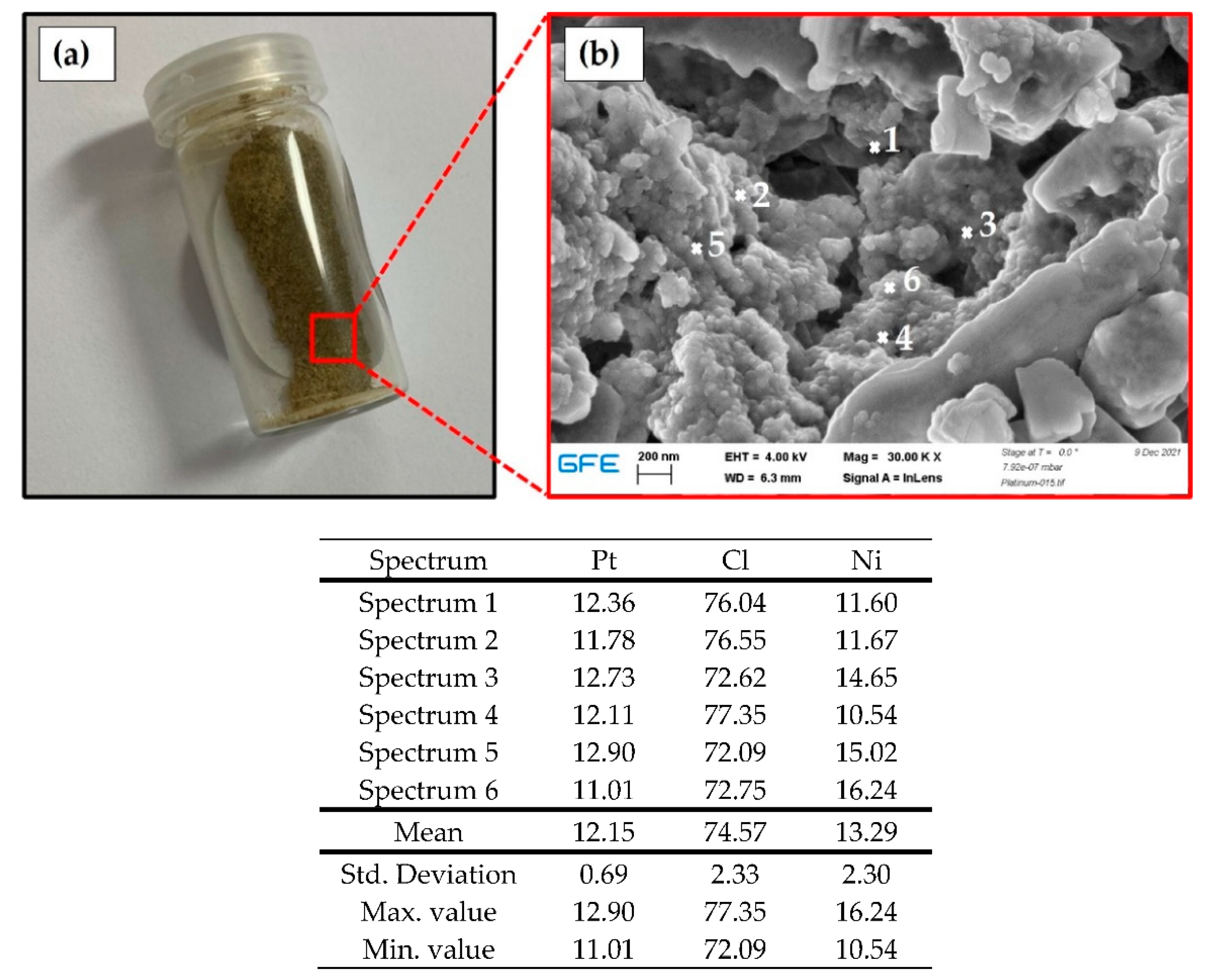
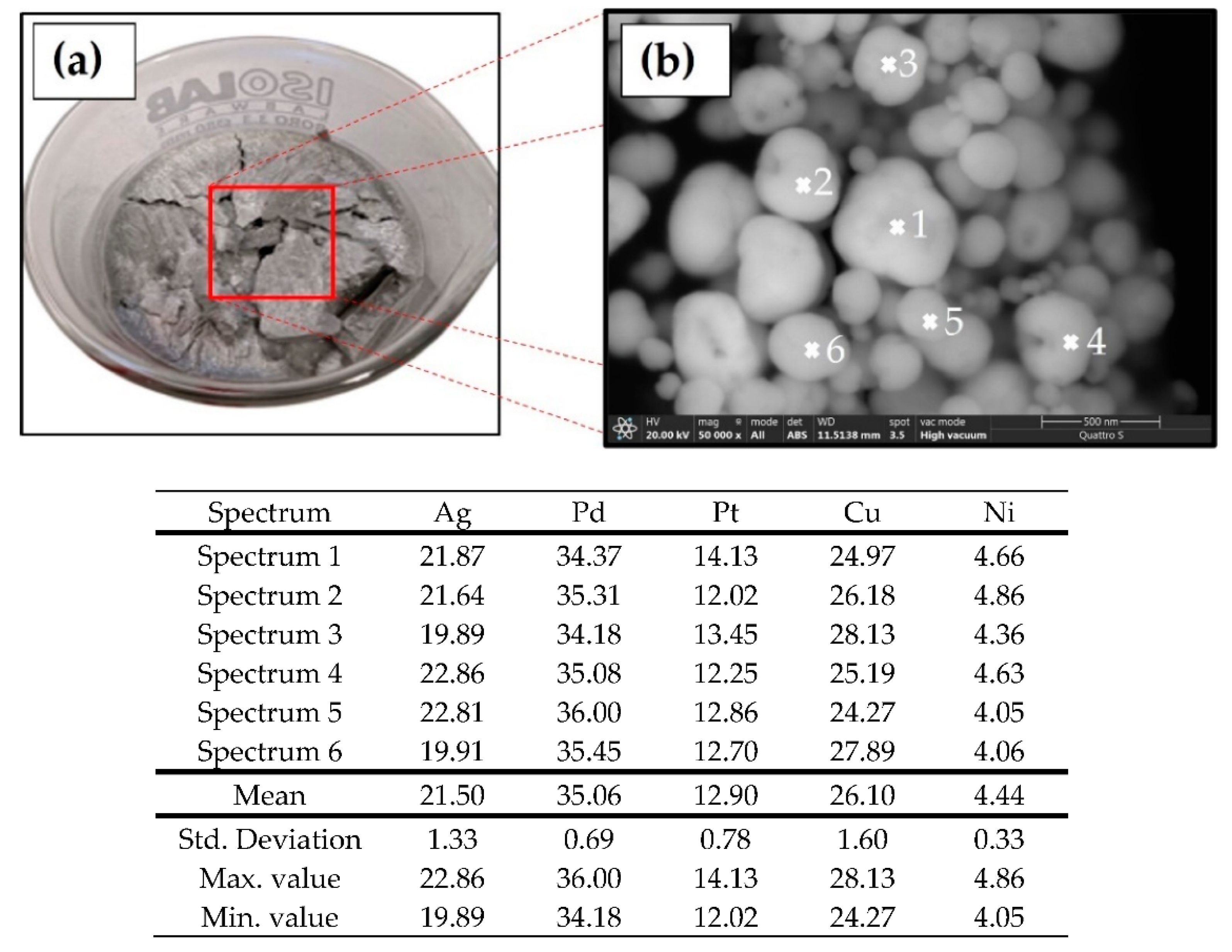
3.5. SEM Observations with EDS Analysis
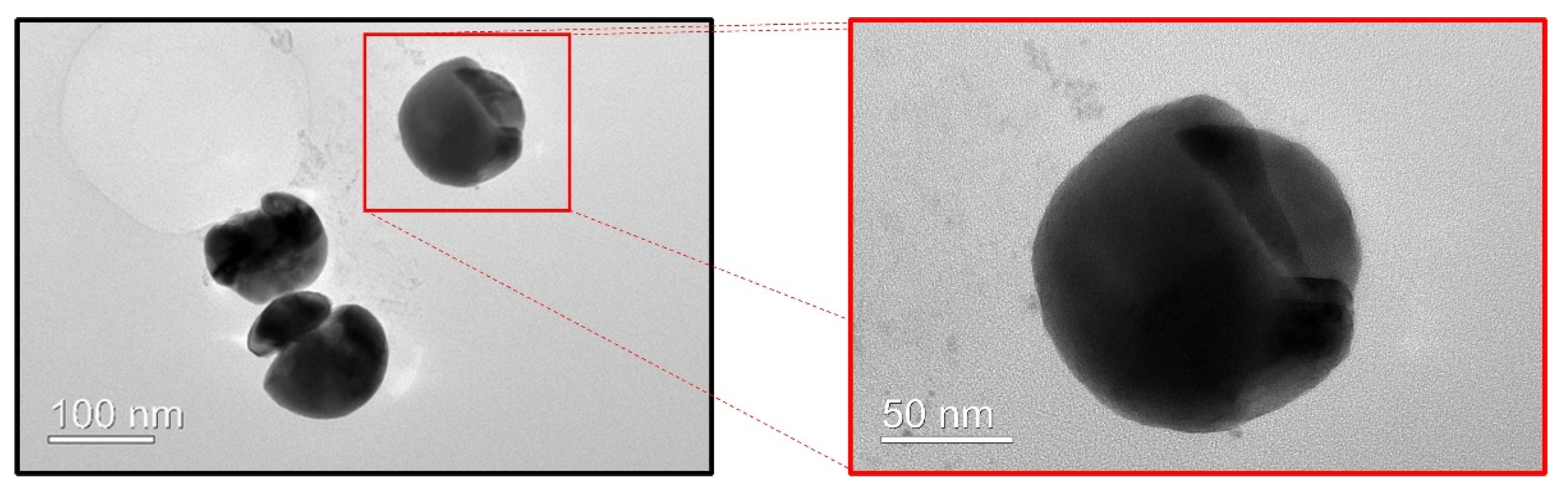
3.6. TEM
3.7. Statistics
4. Results and Discussion
4.1. XRF of Cast Alloy
4.2. ICP-OES
4.2.1. Precursor
4.2.2. Suspension with CCNPs
4.3. DLS Method and Zeta Potential Measurements
4.4. XRD Results
4.5. SEM Observations with EDS Analysis
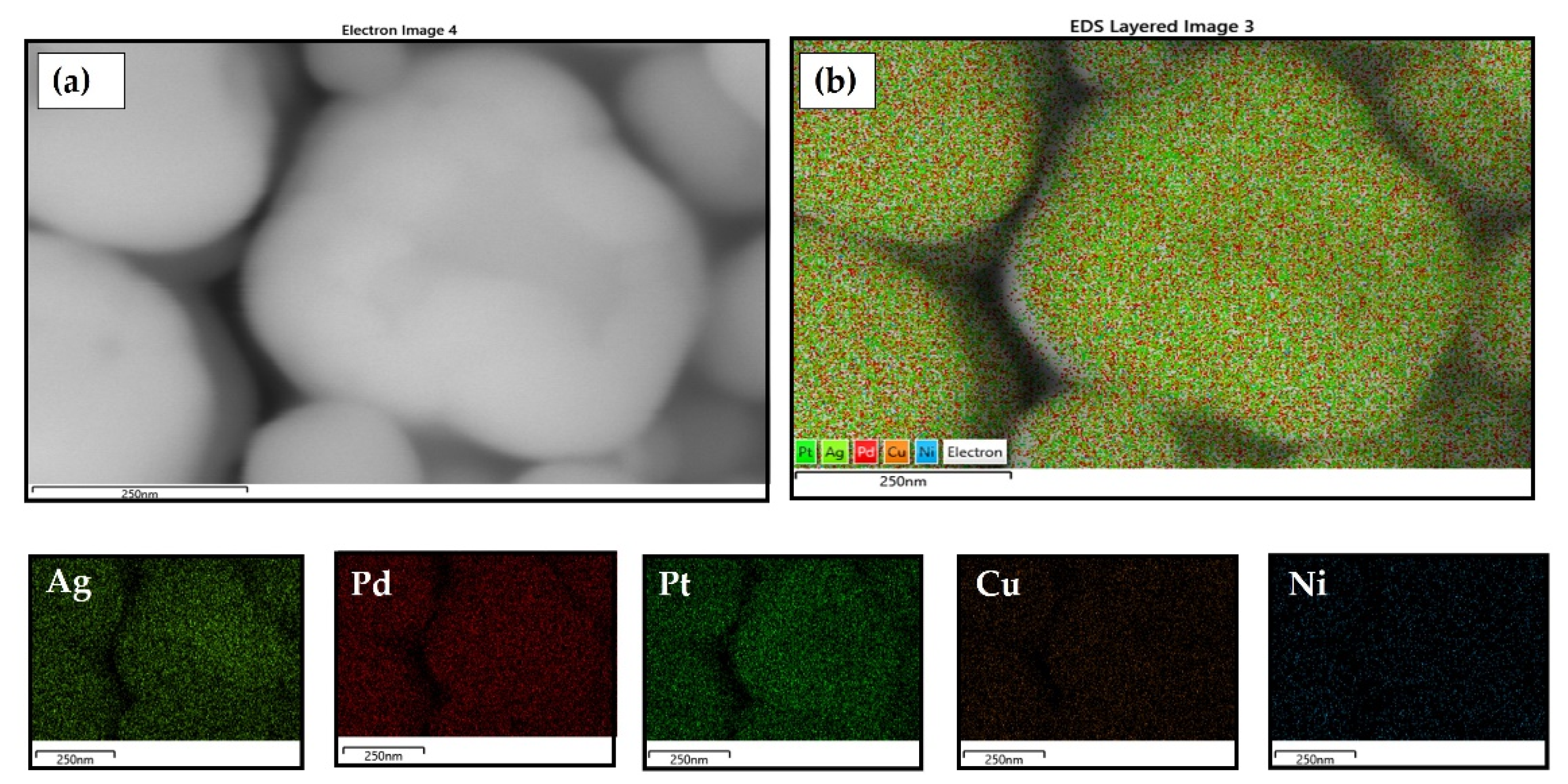
4.6. Transmission Electron Microscopy (TEM)
5. Conclusions
- -
- The hydrometallurgical treatment of the cast Ag20Pd20Pt20Cu20Ni20 alloy, which involves dissolution with nitric acid, results in an incomplete dissolution of the alloy. As a consequence, a precipitate rich in salts is formed: (NH4)2PtCl6, (NH3)6NiPtCl6 × 0.5H2O, Pt2(NH3)4Cl4. The remaining precursor solution, with a reduced at. % of Pt (11.47) and Ni (3.93), was used for the synthesis of nanoparticles by USP;
- -
- The formatted CCNPs contain a high at. % of Pd, Cu, and Ag and a significantly lower at. % of Pt and Ni compared to the chemical composition of the cast Ag20Pd20Pt20Cu20Ni20 alloy;
- -
- Lyophilisation has been recognised as a successful method for removing excess water from a suspension with CCNPs avoiding the sedimentation and agglomeration of the nanoparticles;
- -
- The synthesised CCNPs can be classified as medium entropy materials, as indicated by their calculated configurational entropy;
- -
- The mechanism of the formation of CNNPs by USP was established so that Pd and Cu are formed first, followed by Pt, while Ag and Ni are formed at the end;
- -
- The presented research showed that it may be possible to use USP and lyophilisation for the synthesis of nanoparticles from waste CCAs. With the help of the hydrometallurgical treatment of CCAs, a precursor solution which enables the synthesis of CCNPs with a bottom-up approach could be prepared. In this way, we can conclude that these two used methods represent technological ways of recycling such materials.
Supplementary Materials
Author Contributions
Funding
Acknowledgments
Conflicts of Interest
Abbreviations
| CCAs | complex concentrated alloys |
| CCNPs | complex concentrated nanoparticles |
| DLS | dynamic light scattering |
| EDS | energy dispersive X-ray spectrometer |
| HEA | high-entropy alloy |
| ICP–OES | inductively coupled plasma–optical emission spectrometry |
| PVP | polyvinylpyrrolidone |
| SEM | scanning electron microscopy |
| TEM | transmission electron microscopy |
| USP | ultrasonic spray pyrolysis |
| XRF | X-ray fluorescence spectroscopy |
References
- Zhang, Y.; Zuo, T.T.; Tang, Z.; Gao, M.C.; Dahmen, K.A.; Liaw, P.K.; Lu, Z.P. Microstructures and properties of high-entropy alloys. Prog. Mater. Sci. 2014, 61, 1–93. [Google Scholar] [CrossRef]
- Raabe, D.; Tasan, C.C.; Springer, H.; Bausch, M. From high-entropy alloys to high-entropy steels. Steel Res. Int. 2015, 86, 1127–1138. [Google Scholar] [CrossRef]
- Miracle, D.B.; Senkov, O.N. A critical review of high entropy alloys and related concepts. Acta Mater. 2017, 122, 448–511. [Google Scholar] [CrossRef] [Green Version]
- Tiyyagura, H.R.; Majerič, P.; Anžel, I.; Rudolf, R. Low-cost synthesis of AuNPs through ultrasonic spray pyrolysis. Mater. Res. Express 2020, 7, 055017. [Google Scholar] [CrossRef]
- Yang, Y.; Song, B.; Ke, X.; Xu, F.; Bozhilov, K.N.; Hu, L.; Shahbazian-Yassar, R.; Zachariah, M.R. Aerosol Synthesis of High Entropy Alloy Nanoparticles. Langmuir 2020, 36, 1985–1992. [Google Scholar] [CrossRef]
- Yeh, J.W. Alloy design strategies and future trends in high-entropy alloys. JOM 2013, 65, 1759–1771. [Google Scholar] [CrossRef]
- Majerič, P.; Rudolf, R. Advances in ultrasonic spray pyrolysis processing of noble metal nanoparticles-Review. Materials 2020, 13, 3485. [Google Scholar] [CrossRef]
- Rahemi Ardekani, S.; Sabour Rouh Aghdam, A.; Nazari, M.; Bayat, A.; Yazdani, E.; Saievar-Iranizad, E. A comprehensive review on ultrasonic spray pyrolysis technique: {Mechanism}, main parameters and applications in condensed matter. J. Anal. Appl. Pyrolysis 2019, 141, 104631. [Google Scholar] [CrossRef]
- Stopić, S.; Dvorak, P.; Friedrich, B. Synthesis of spherical nanosized copper powder by ultrasonic spray pyrolysis. World Metall. -ERZMETALL 2005, 58, 191–197. [Google Scholar]
- Stopic, S.; Friedrich, B.; Schroeder, M.; Weirich, T.E. Synthesis of TiO2 core/RuO2 shell particles using multistep ultrasonic spray pyrolysis. Mater. Res. Bull. 2013, 48, 3633–3635. [Google Scholar] [CrossRef]
- Gürmen, S.; Stopić, S.; Friedrich, B. Synthesis of nanosized spherical cobalt powder by ultrasonic spray pyrolysis. Mater. Res. Bull. 2006, 41, 1882–1890. [Google Scholar] [CrossRef]
- Kaya, E.E.; Kaya, O.; Stopic, S.; Gürmen, S.; Friedrich, B. Ndfeb magnets recycling process: An alternative method to produce mixed rare earth oxide from scrap ndfeb magnets. Metals 2021, 11, 716. [Google Scholar] [CrossRef]
- Kumar Katiyar, N.; Biswas, K.; Yeh, J.-W.; Sharma, S.; Sekhar Tiwary, C. A perspective on the catalysis using the high entropy alloys. Nano Energy 2021, 88, 106261. [Google Scholar] [CrossRef]
- Xie, P.; Yao, Y.; Huang, Z.; Liu, Z.; Zhang, J.; Li, T.; Wang, G.; Shahbazian-Yassar, R.; Hu, L.; Wang, C. Highly efficient decomposition of ammonia using high-entropy alloy catalysts. Nat. Commun. 2019, 10, 4011. [Google Scholar] [CrossRef] [Green Version]
- Nellaiappan, S.; Katiyar, N.K.; Kumar, R.; Parui, A.; Malviya, K.D.; Pradeep, K.G.; Singh, A.K.; Sharma, S.; Tiwary, C.S.; Biswas, K. High-Entropy Alloys as Catalysts for the CO2 and CO Reduction Reactions: Experimental Realization. ACS Catal. 2020, 10, 3658–3663. [Google Scholar] [CrossRef]
- Huang, X.; Yang, G.; Li, S.; Wang, H.; Cao, Y.; Peng, F.; Yu, H. Noble-metal-based high-entropy-alloy nanoparticles for electrocatalysis. J. Energy Chem. 2022, 68, 721–751. [Google Scholar] [CrossRef]
- Rudolf, R. Cast Microstructure of a Complex Concentrated Noble Alloy. Materials 2022, 15, 4788. [Google Scholar]
- Köroğlu, M.; Ebin, B.; Stopic, S.; Gürmen, S.; Friedrich, B. One step production of silver-copper (Agcu) nanoparticles. Metals 2021, 11, 1466. [Google Scholar] [CrossRef]
- Tang, Z.; Jung, E.; Jang, Y.; Bhang, S.H.; Kim, J.; Kim, W.-S.; Yu, T. Facile Aqueous-Phase Synthesis of Bimetallic. Materials 2020, 13, 254. [Google Scholar] [CrossRef] [Green Version]
- Rudolf, R.; Friedrich, B.; Stopić, S.; Anžel, I.; Tomić, S.; Čolić, M. Cytotoxicity of gold nanoparticles prepared by ultrasonic spray pyrolysis. J. Biomater. Appl. 2012, 26, 595–612. [Google Scholar] [CrossRef]
- Jelen, Ž.; Majerič, P.; Zadravec, M.; Anžel, I.; Rakuša, M.; Rudolf, R. Study of gold nanoparticles’ preparation through ultrasonic spray pyrolysis and lyophilisation for possible use as markers in LFIA tests. Nanotechnol. Rev. 2021, 10, 1978–1992. [Google Scholar] [CrossRef]
- Abdelwahed, W.; Degobert, G.; Stainmesse, S.; Fessi, H. Freeze-drying of nanoparticles: Formulation, process and storage considerations. Adv. Drug Deliv. Rev. 2006, 58, 1688–1713. [Google Scholar] [CrossRef] [PubMed]
- Psimadas, D.; Georgoulias, P.; Valotassiou, V.; Loudos, G. Molecular Nanomedicine Towards Cancer. J. Pharm. Sci. 2012, 101, 2271–2280. [Google Scholar] [CrossRef]
- Singh, S.K.; Xu, Q. Bimetallic Ni?Pt nanocatalysts for selective decomposition of hydrazine in aqueous solution to hydrogen at room temperature for chemical hydrogen storage. Inorg. Chem. 2010, 49, 6148–6152. [Google Scholar] [CrossRef] [PubMed]
- Mu, X.D.; Evans, D.G.; Kou, Y. A general method for preparation of PVP-stabilized noble metal nanoparticles in room temperature ionic liquids. Catal. Letters 2004, 97, 151–154. [Google Scholar] [CrossRef]
- Rostek, A.; Breisch, M.; Pappert, K.; Loza, K.; Heggen, M.; Köller, M.; Sengstock, C.; Epple, M. Comparative biological effects of spherical noble metal nanoparticles (Rh, Pd, Ag, Pt, Au) with 4-8 nm diameter. Beilstein J. Nanotechnol. 2018, 9, 2763–2774. [Google Scholar] [CrossRef]
- Wang, H.; Qiao, X.; Chen, J.; Wang, X.; Ding, S. Mechanisms of PVP in the preparation of silver nanoparticles. Mater. Chem. Phys. 2005, 94, 449–453. [Google Scholar] [CrossRef]
- Stopić, S.; Ilić, I.; Uskoković, D. Structural and morphological transformations during NiO and Ni particles generation from chloride precursor by ultrasonic spray pyrolysis. Mater. Lett. 1995, 24, 369–376. [Google Scholar] [CrossRef]
- Švarc, T.; Stopić, S.; Jelen, Ž.; Zadravec, M.; Friedrich, B.; Rudolf, R. Synthesis of Ni/Y2O3 Nanocomposite through USP and Lyophilisation for Possible Use as Coating. Materials 2022, 15, 2856. [Google Scholar] [CrossRef]
- Dauthal, P.; Mukhopadhyay, M. Noble Metal Nanoparticles: Plant-Mediated Synthesis, Mechanistic Aspects of Synthesis, and Applications. Ind. Eng. Chem. Res. 2016, 55, 9557–9577. [Google Scholar] [CrossRef]
- Shariq, M.; Majerič, P.; Friedrich, B.; Budic, B.; Jenko, D.; Dixit, A.R.; Rudolf, R. Application of Gold(III) Acetate as a New Precursor for the Synthesis of Gold Nanoparticles in PEG Through Ultrasonic Spray Pyrolysis. J. Clust. Sci. 2017, 28, 1647–1665. [Google Scholar] [CrossRef]
- Ravnik, J.; Ramšak, M.; Zadravec, M.; Kamenik, B.; Hriberšek, M. Experimental and stochastic analysis of lyophilisation. Eur. J. Pharm. Biopharm. 2021, 159, 108–122. [Google Scholar] [CrossRef] [PubMed]
- De Temmerman, P.J.; Lammertyn, J.; De Ketelaere, B.; Kestens, V.; Roebben, G.; Verleysen, E.; Mast, J. Measurement uncertainties of size, shape, and surface measurements using transmission electron microscopy of near-monodisperse, near-spherical nanoparticles. J. Nanoparticle Res. 2014, 16, 2177. [Google Scholar] [CrossRef]
- Horike, C.; Morita, K.; Okabe, T.H. Effective dissolution of platinum by using chloride salts in recovery process. Metall. Mater. Trans. B: Process Metall. Mater. Process. Sci. 2012, 43, 1300–1307. [Google Scholar] [CrossRef] [Green Version]
- Takeuchi, A.; Inoue, A. Calcualtion of mixing enthalpy and mismatch entropy. Mater. T 2000, 41, 1372–1378. [Google Scholar]
- Copyright (c) 1996-2021 CrystalMaker Software Limited. Available online: crystalmaker.com (accessed on 20 December 2021).
- Lin, P.C.; Lin, S.; Wang, P.C.; Sridhar, R. Techniques for physicochemical characterization of nanomaterials. Biotechnol. Adv. 2014, 32, 711–726. [Google Scholar] [CrossRef] [PubMed] [Green Version]
- Thompson, J.F.; Miller, E.H. Platinum silver alloys. J. Am. Chem. Soc. 1906, 28, 1115–1132. [Google Scholar] [CrossRef]


| Element | Ag | Pd | Pt | Cu | Ni |
|---|---|---|---|---|---|
| wt. % | 0.0062 | 0.010 | 0.0092 | 0.0074 | 0.0016 |
| at. % | 18.83 | 19.40 | 20.46 | 20.10 | 21.21 |
| Element | Ag | Pd | Pt | Cu | Ni |
|---|---|---|---|---|---|
| g/L | 0.64 | 0.85 | 0.58 | 0.51 | 0.06 |
| at. % | 22.87 | 30.79 | 11.47 | 30.94 | 3.93 |
| Element | Ag | Pd | Pt | Cu | Ni |
|---|---|---|---|---|---|
| g/L | 6.2 | 10.2 | 9.2 | 7.4 | 1.6 |
| at. % | 16.62 | 27.73 | 13.60 | 34.24 | 7.81 |
| ΔHmix [kJ/mol] | |||||||||
|---|---|---|---|---|---|---|---|---|---|
| Ag | Pd | Pt | Cu | Ni | |||||
| AgPd | −7 | PdAg | −7 | PtAg | −1 | CuAg | 2 | NiAg | 15 |
| AgPt | −1 | PdPt | 2 | PtPd | 2 | CuPd | −14 | NiPd | 0 |
| AgCu | 2 | PdCu | −14 | PtCu | −12 | CuPt | −12 | NiPt | −5 |
| AgNi | 15 | PdNi | 0 | PtNi | −5 | CuNi | 4 | NiCu | 4 |
Publisher’s Note: MDPI stays neutral with regard to jurisdictional claims in published maps and institutional affiliations. |
© 2022 by the authors. Licensee MDPI, Basel, Switzerland. This article is an open access article distributed under the terms and conditions of the Creative Commons Attribution (CC BY) license (https://creativecommons.org/licenses/by/4.0/).
Share and Cite
Simić, L.; Stopic, S.; Friedrich, B.; Zadravec, M.; Jelen, Ž.; Bobovnik, R.; Anžel, I.; Rudolf, R. Synthesis of Complex Concentrated Nanoparticles by Ultrasonic Spray Pyrolysis and Lyophilisation. Metals 2022, 12, 1802. https://doi.org/10.3390/met12111802
Simić L, Stopic S, Friedrich B, Zadravec M, Jelen Ž, Bobovnik R, Anžel I, Rudolf R. Synthesis of Complex Concentrated Nanoparticles by Ultrasonic Spray Pyrolysis and Lyophilisation. Metals. 2022; 12(11):1802. https://doi.org/10.3390/met12111802
Chicago/Turabian StyleSimić, Lidija, Srecko Stopic, Bernd Friedrich, Matej Zadravec, Žiga Jelen, Rajko Bobovnik, Ivan Anžel, and Rebeka Rudolf. 2022. "Synthesis of Complex Concentrated Nanoparticles by Ultrasonic Spray Pyrolysis and Lyophilisation" Metals 12, no. 11: 1802. https://doi.org/10.3390/met12111802