Communication

Effect of Structure of Carbonized Polymer Dot on the Mechanical and Electrical Properties of Copper Matrix Composites

1
Faculty of Materials Metallurgy and Chemistry, Jiangxi University of Science and Technology, Ganzhou 341000, China
2
School of Materials Science and Engineering, Kunming University of Science and Technology, Kunming 650093, China
*
Authors to whom correspondence should be addressed.
Metals 2022, 12(10), 1701; https://doi.org/10.3390/met12101701
Submission received: 19 September 2022 / Revised: 9 October 2022 / Accepted: 10 October 2022 / Published: 11 October 2022

Abstract

:
Carbonized polymer dots (CPDs) have been paid a lot of attention by researchers because of their excellent properties due to their unique structure. However, few studies have researched the impact of the CPD structure on composite applications. Herein, CPD and heat-treated CPD (h-CPD) are used to fabricate a reinforced Cu matrix composite. There was a semi-coherent interface between h-CPD and Cu. However, functional groups and polymer chains of CPDs decomposed during heat treatment, weakening the mechanical and electrical properties of the composites. These findings show that CPD structural integrity is vital to composites.

1. Introduction

When it comes to determining the performance of carbon nano-material (CNM)/Cu composites, the most important aspects are good dispersion and strong reinforcement–matrix interfacial cohesion, both of which are the foci of study in the area of Cu-based composites [1]. Many effective methods have been developed for fabrication of CNM/Cu composites with good dispersion and tight interface bonding.
For example, by adjusting the acid-treatment time of Carbon nanotubes (CNTs) to produce carboxyl and other ionogenic groups, Yang et al. found that uniformly distributed CNT was obtained by extending the acid-treatment time [2]. Chu reported a new design for producing defects on the graphene (GR) basal-plane to optimize the interface and mechanical properties of GR/CuCr composites by the formation of Cr7C3 at the basal-plane/matrix interface [3]. Carbonized polymer dots (CPDs), which have structural characteristics of GR and CNT, as well as rich surface functional groups and water solvent dispersion, have been employed to reinforce a Cu-based matrix as a nano-carbon reinforcement [4]. These CPDs for Cu-based composite application, however, have polymer chains and oxygen-containing functional groups that are introduced during the preparation or when raw materials, which makes them more reactive than perfect CNT and GR, leading to the interfacial structure and bonding state between CPD and Cu matrix being affected.
Here, in this paper, effort was made to reveal how the structural characteristics of CPD affect the mechanical and electrical properties of Cu-based composites. We prepared heat treated CPD (h-CPD)/Cu composites by combining ball milling with spark plasma sintering (SPS). Moreover, the mechanical properties, electrical conductivity, microstructure and strengthening, and the conductivity mechanism of the h-CPD/Cu composites were carefully compared, in detail, with those of CPD/Cu composite prepared in the same way. It was found that the functional groups and polymer chains of CPD were beneficial to the Cu matrix, imparting outstanding mechanical and electrical properties.

2. Experiment

CPD was synthesized by hydrothermal means, the details of which are in our previous work [5]. In this work, the h-CPD was obtained by heat treatment of CPD at 300, 500, 700 and 900 °C, respectively. The products were labeled as h1-CPD, h2-CPD, h3-CPD and h4-CPD. It is worth noting that h-CPD cooled with the furnace immediately after heating to a specific temperature, and the whole process was carried out in an atmosphere of Ar. Then, the h-CPDs were dissolved in anhydrous ethanol and ball milled with pure Cu powders (ball milled parameters: 100 rpm 8 h + 200 rpm 5 h, and the mass fraction of the h-CPD was 0.2%). Finally, the composite powders were reduced (300 °C in a N2-10% H2 mixed atmosphere, for 6 h) and sintered by SPS in a vacuum environment at 550 °C for 5 min to obtain h-CPD/Cu composites. The CPD/Cu and Cu matrix was prepared under the same experimental conditions.
The h-CPD microstructures were studied by transmission electron microscopy (TEM, Tecnai G2-TF20, S-Twin, FEI company, Hillsboro, OR, USA), and X-ray photoelectron spectroscopy (XPS, K-Alpha+, Thermo Fisher Scientific, Waltham, MA, USA). The interface microstructure of the composites was analyzed by TEM. A tensile test was conducted with AG-IS 10 KN equipment (Shimadzu Corporation, Kyoto, Japan) with a crosshead speed of 0.5 mm/min at room temperature. Electrical conductivity of the composites was tested by means of a digital conductivity meter (Sigma 2008B, Xiamen Tianyan Instrument Co., Ltd., Xiamen, China). The fracture surface of h-CPD/Cu composites was analyzed via scanning electron microscopy (SEM, Nova Namo-450, FEI company, Hillsboro, OR, USA).

3. Results and Discussion
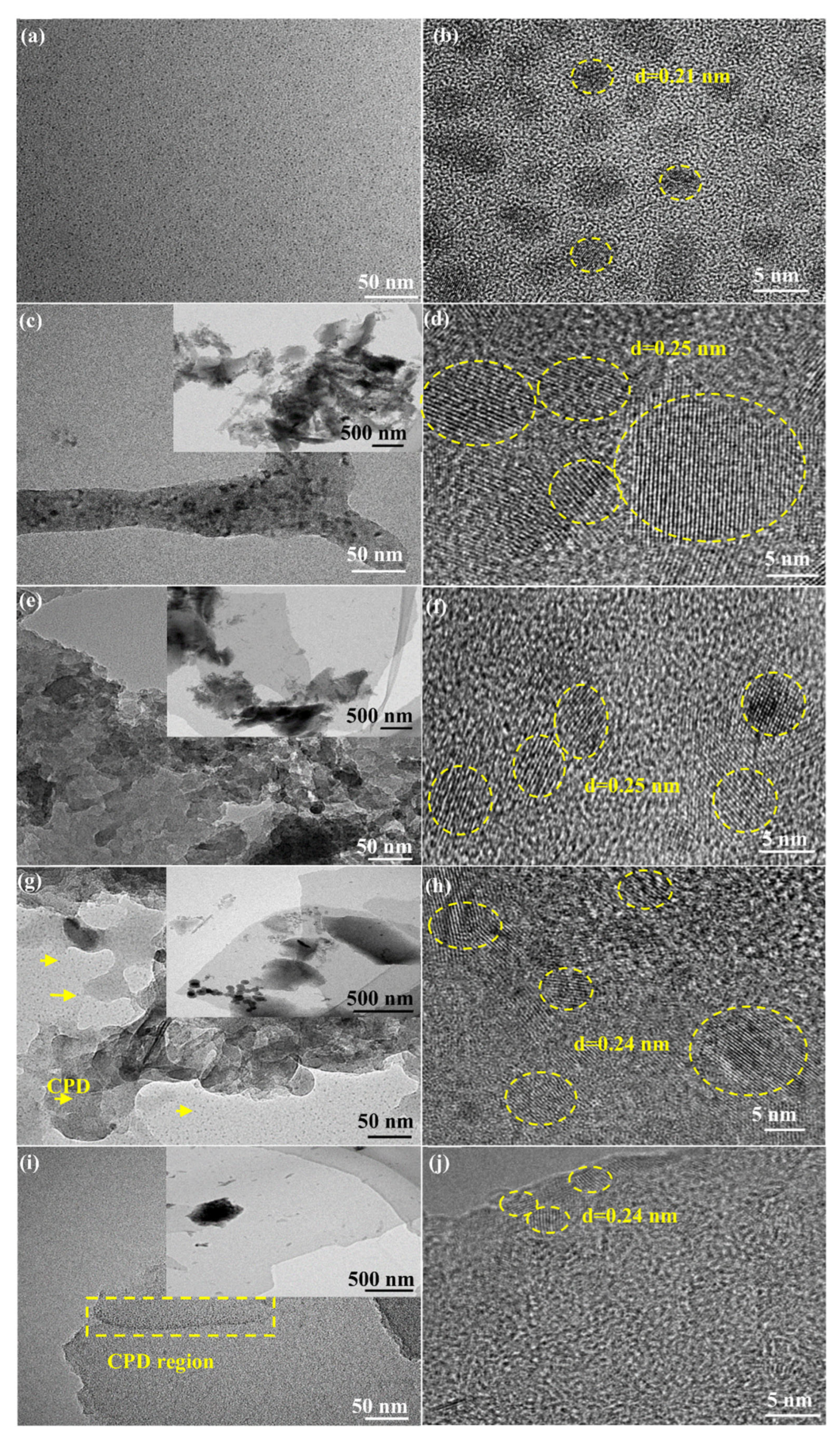
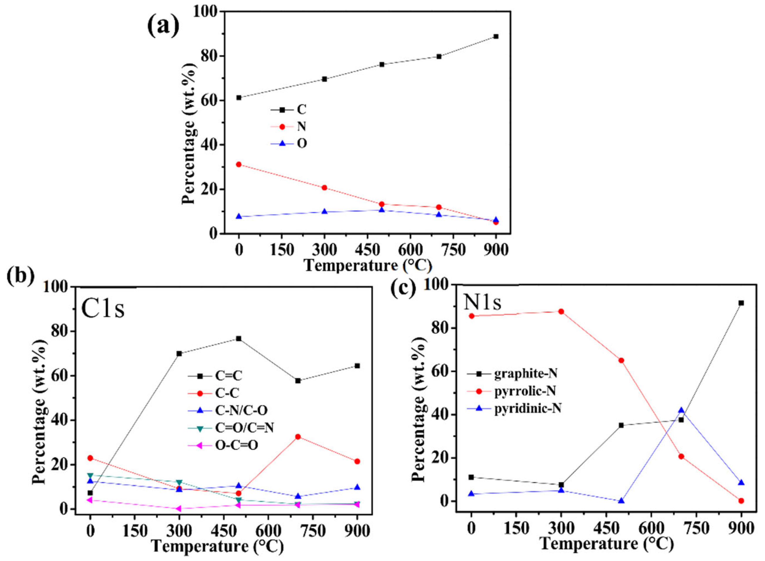
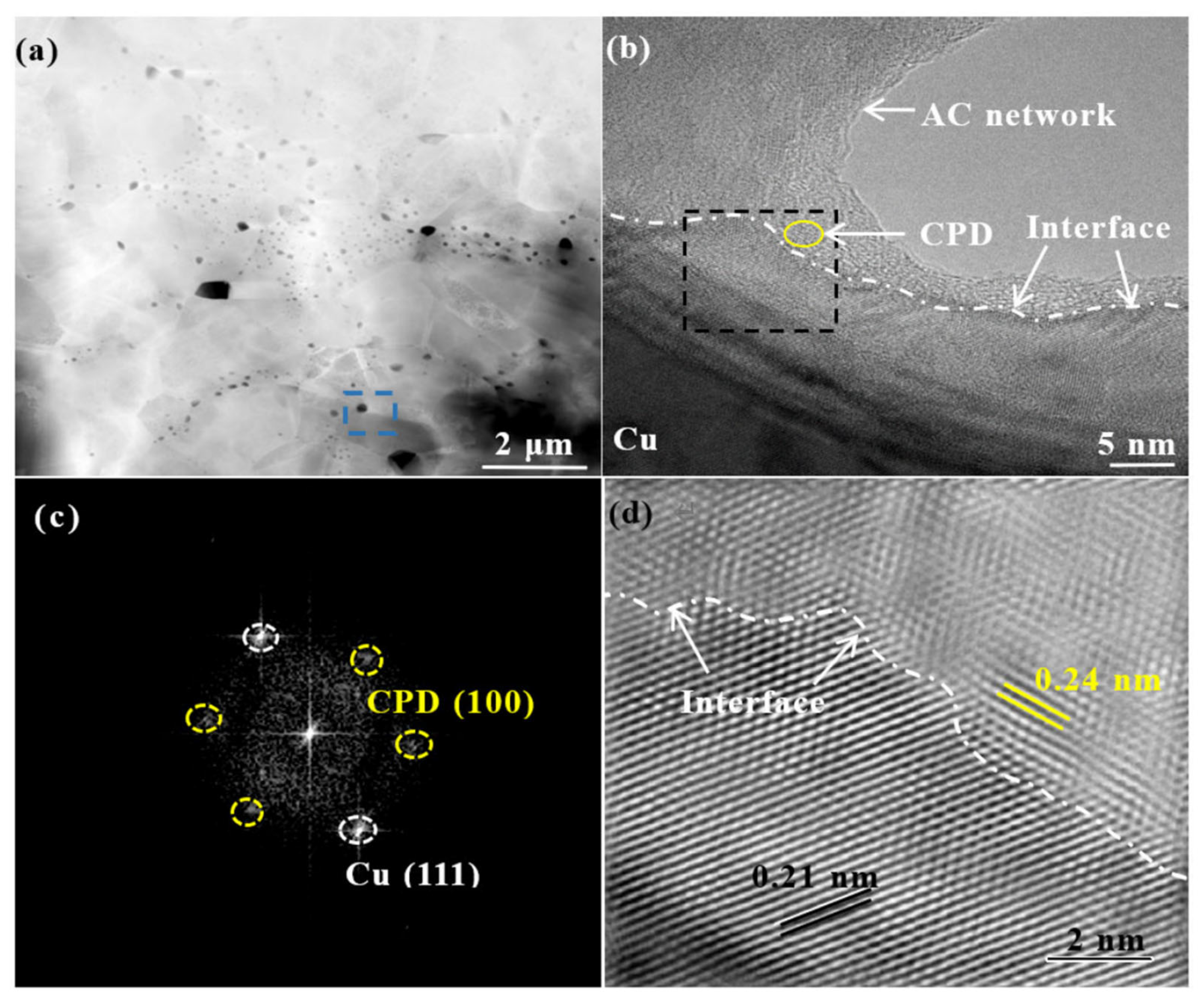
3.1. Microstructure

Figure 1a,b reveals the microstructure of CPD synthesized by hydrothermal means, which had a near-spherical distribution, with a lattice spacing of around 0.21 nm and a mean diameter of approximately 3.0 nm. Contrary to CPD, h1-CPD exhibited a thick lamellar morphology and nanoparticles, suggesting that after heat treatment at 300 °C, some CPDs were still intact and combined to form nanoparticles (Figure 1c). The diameter of the nanoparticles observed increased as shown in Figure 1d. This was due to the fact that the CPDs obtained hydrothermally were not in a single, distributed form but instead preferred to attach to one another. In addition, with further magnification of h1-CPD, it was discovered that certain lamellar structures exhibited an amorphous structure, while others showed distinct lattice fringes (~0.25 nm) (seen Figure 1d) and had similar morphology and structure to that of CPD. The increase of amorphous area in h2-CPD lamellar structure suggested that following heat treatment at 500 °C, most CPD structures were damaged (see Figure 1e,f). Interestingly, there was homogeneous distribution of nanoparticles in the h3-CPD thin lamellar structures. However, when the heat treatment temperature was raised to 900 °C, there were only a few nanoparticles along the h4-CPD flakes, and their size and quantity decreased. This was attributed to the fact that, after heating at 300 °C, cross-linking occurred between CPD molecules to avoid collapse, and carbonization proceeded as the temperature rose to 500, 700 °C, resulting in the formation of a self-supporting nitrogen-doped carbon lamellar structure. As the temperature continued to increase to 900 °C, the three-dimensional nitrogen-doped carbon lamellar structure was further carbonized and destroyed, giving birth to a lot of amorphous carbon. The lamellar thickness, smoothness, and diameter of h-CPD fluctuated dramatically when heat-treated at various temperatures. This was primarily due to variations in the stability of polymer chains and functional groups on the CPD surfaces.
XPS was utilized to better investigate the chemical structural changes of CPD following heat treatment (see Figure 2a–c). All samples were carbon-rich and included carbon, oxygen and nitrogen. The C, O and N contents of samples at various heat treatment temperatures are shown in Figure 2a. It was discovered that with the increment of heat treatment temperature, the C wt.% in CPD improved from 61.11% to 88.70%, O wt.% increased from 7.28% to 10.50% and then dropped to 5.22%, and N wt.% reduced from 31.25% to 6.08%. These changes implied that the hydrothermally synthesized CPD was carbonized again following heat treatment, and the surface polymer chains and functional groups were degraded at high temperature, leading to a drop in O wt.% and N wt.%. According to Figure 2b, as the heat treatment temperature improved in C1s, the contents of C=C, C-C, C-N/C-O, C=O/C=N, and O-C=O [5] all changed. Importantly, C=C increased significantly at first and then decreased. The C=C bond compositions of h3-CPD and h4-CPD were, however, essentially the same. This showed that when the heat treatment temperature rose to 700 °C, the polymer chain and functional groups on the CPD surface decomposed and the remaining C=C bonds were mostly from the C-core of h-CPD, and the C-core of h-CPD had thermal stability. Furthermore, the pattern of change in C-C bond composition was opposite to that of the C=C bond. This suggested that at high temperatures, part of the structure in h-CPD was destroyed and the sp3 C component was generated, which was consistent with the TEM morphology of h-CPD. In N1s (see Figure 2c), it could be clearly observed that N-containing species in CPD were converted from pyrrolic-N to pyridine-N and graphite-N after heat treatment, indicating N-doping with CPD [6].
Figure 3 gives the microstructure of the h3-CPD/Cu composite, which was different from CPD/Cu composites [4]. Observed under low magnification TEM, the h3-CPDs were discovered in the Cu grains (see yellow arrows in Figure 3a). The blue wire frame in Figure 3a is magnified in Figure 3b, and a large amount of amorphous carbon (AC) network existed in the non-matrix area, and a small amount of CPD with full lattice fringe still persisted in the AC network (yellow ellipse in Figure 3b), which indicated that the structure of CPD was destroyed after heat treatment, ball milling and SPS sintering. In addition, as shown by the white dotted line in Figure 3b, there was a clear separation between h3-CPD and Cu. The black dotted line portion in Figure 3b was subjected to Fourier transform (FFT) and inverse Fourier transform (IFFT) processing in order to further evaluate the interface. The findings are shown in Figure 3c,d. First of all, there was a lot of AC. Second, three groups of diffraction dots also showed up. It was found that the lattice spacings were typically ~0.21 nm, 0.24 nm and 0.24 nm, for the d-spacing (111) in the crystal plane of the Cu matrix (~0.209 nm), and the two sets of diffraction dots with a d-spacing of 0.24 nm corresponded to d-spacing (100) in the crystal plane of h3-CPD. To clarify the interface structure, the misfit parameter, ε, was described by the following equation [7]:
ε = d h 3 C P D d Cu d Cu
where dh3-CPD and dCu are the interplanar spacings of the Cu (111) and h3-CPD (100) planes. The calculated parameter was 0.14, which indicated that the interface between the Cu matrix and h3-CPD was semi-coherent. The semi-coherent interface generally exhibited a relatively low interfacial energy, which was beneficial to the formation of a strong interfacial bonding between h3-CPD and the Cu matrix [8].

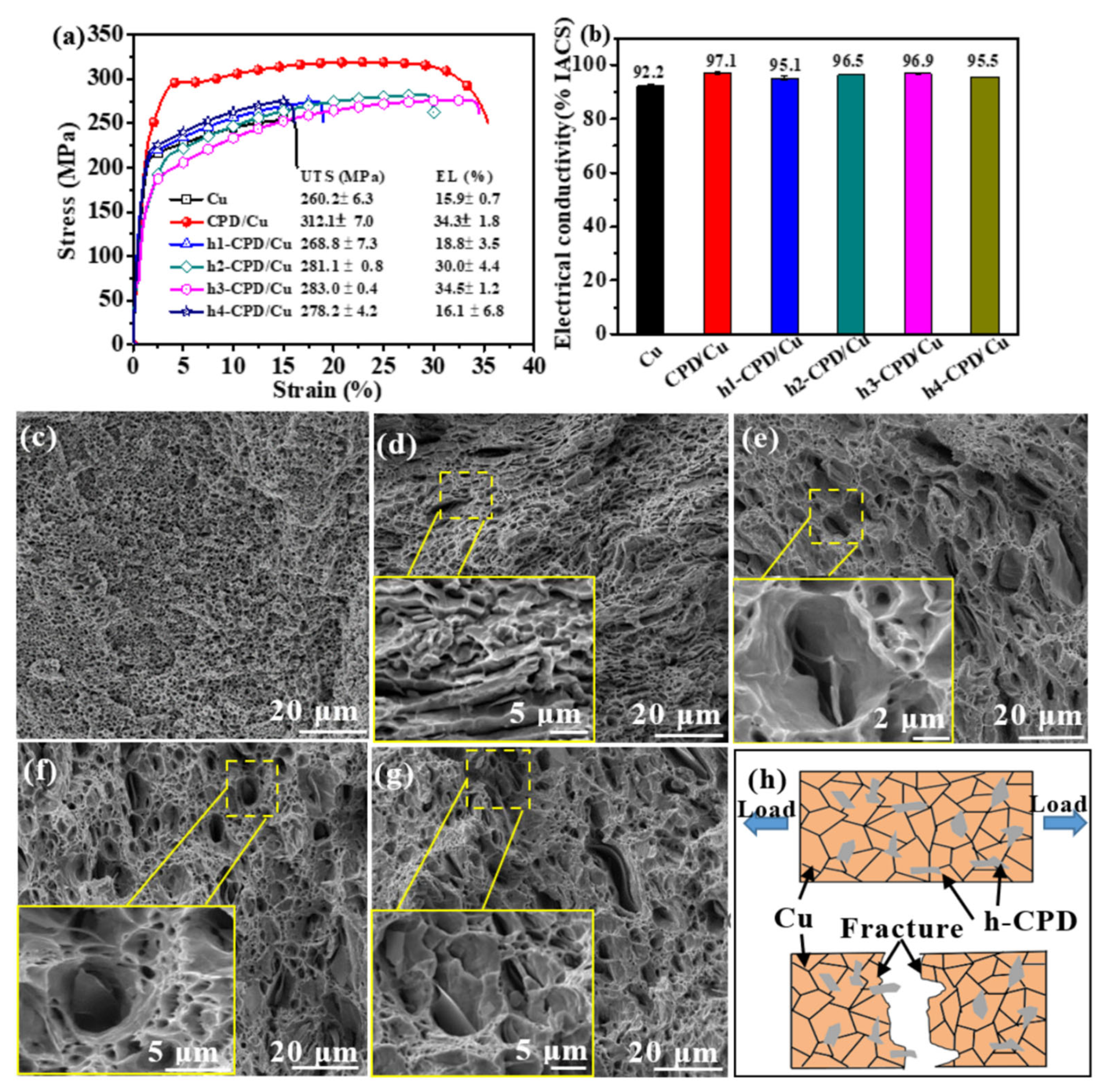
3.2. Mechanical Properties of Bulk Specimens

As shown in Table 1, the sintered bulk materials were near full densification. Figure 4a shows the stress–strain curves for the samples. Pure Cu had an ultra-tensile strength (UTS) of 260.2 ± 6.3 MPa and its elongation (EL) was 15.9 ± 0.7%. The CPD/Cu sample’s UTS was 312.1 ± 7.0 MPa, and its EL was 34.3 ± 1.8%, which suggested the addition of CPD improved the mechanical property of the Cu matrix. For h1-CPD/Cu, the UTS was 268.1 ± 7.3 MPa, and the EL was 18.8 ± 3.5%. For h2-CPD, h3-CPD/Cu samples, the values for UTS and EL were enhanced, compared with pure Cu, and the values were 281.1 ± 0.8 MPa, 30.0 ± 4.4%; 283.0 ± 0.8 MPa, 34.5 ± 1.2%, which was mainly due to the semi-coherent interface formed between h-CPD and Cu. The semi-coherent interface promoted load transfer. In contrast to CPD/Cu composites, however, the surface functional groups and organic chains of CPD were decomposed to varying degrees during heat treatment. As a result, a significant amount AC was formed (as shown in Figure 3), lowering the mechanical properties of the composites. UTS (278.2 ± 4.2 MPa) and EL (16.1 ± 6.8%) of the h4-CPD/Cu sample were reduced to values near those of pure Cu.
The electrical conductivities of the samples are shown in Figure 3b. Pure Cu was 92.2 ± 0.7%IACS. All Cu-based composites were higher than pure Cu. Specifically, CPD/Cu was 97.1 ± 0.4%IACS, h1-CPD/Cu was 95.1 ± 0.7%IACS, h2-CPD/Cu was 96.5 ± 0.2%IACS, h3-CPD/Cu was 96.9 ± 0.1%IACS, and h4-CPD/Cu was 95.5 ± 0.2% IACS. Both CPD and h-CPD had high conductivity due to the presence of pyridine-N, pyrrolic-N, and graphite-N. The reason for this was because following N doping, there was an increase in the density of unoccupied charge transport states, which showed that the charge transferred from C to the more electronegative N, improving the composites’ conductivities [9,10]. Additionally, CPD functions well as an electron carrier itself [11]. However, once CPD was heated, the structure was disrupted, which resulted in a minor drop in the electrical conductivity of h-CPD/Cu composites.
Figure 4c–g shows the fracture morphology of samples after a tensile test. All samples showed ductile fracture properties, evidenced by the dimples on the fracture surface. Pull-out h-CPD could be seen on the fracture surface (Figure 4d,g), which suggested load transfer from the Cu matrix to reinforcements during tensile testing, in contrast to the fracture morphology of pure Cu (see Figure 4c). The h-CPD was clearly adherent and embedded in the Cu matrix, which was inseparable from the strong interface bonding.

4. Conclusions

In summary, h-CPD/Cu composites were prepared, together with pure Cu and CPD/Cu, under the same process. The semi-coherent interface increased h-CPD/Cu interface bonding, load transfer, and electron transport. However, h-CPD had a lot of AC, which formed via CPD surface functional groups and polymer chains decomposing during heat treatment, reducing the composite’s mechanical and electrical properties. This study reveals that the structural integrity of CPD helps prepare composites with excellent comprehensive properties.

Author Contributions

Literature search, J.X.; manuscript writing, J.X.; study design, W.Z., R.B. and J.Y.; date analysis, W.Z. and S.L.; making charts, S.L.; date collection, R.B. and Z.L. All authors have read and agreed to the published version of the manuscript.

Funding

This research is funded by the National Natural Science Foundation of China Grant No. 52174345 and 52064032, Scientific Research Starting Foundation for Advanced Talents of Jiangxi University of Science and Technology Grant No. 205200100628.

Institutional Review Board Statement

Not applicable.

Informed Consent Statement

Not applicable.

Data Availability Statement

The date presented in this study are available on request from the corresponding author. The date is not publicly available due to privacy.

Conflicts of Interest

The authors declare no conflict of interest.

References

  1. Zhang, X.; Shi, C.; Liu, E.; Zhao, N.; He, C. Effect of Interface Structure on the Mechanical Properties of Graphene Nanosheets Reinforced Copper Matrix Composites. ACS Appl. Mater. Interfaces 2018, 10, 37586–37601. [Google Scholar] [CrossRef] [PubMed]
  2. Yang, P.; You, X.; Yi, J.; Fang, D.; Bao, R.; Shen, T.; Liu, Y.; Tao, J.; Li, C. Influence of dispersion state of carbon nanotubes on electrical conductivity of copper matrix composites. J. Alloys Compd. 2018, 752, 376–380. [Google Scholar] [CrossRef]
  3. Chu, K.; Wang, J.; Liu, Y.-p.; Li, Y.-b.; Jia, C.-c.; Zhang, H. Creating defects on graphene basal-plane toward interface optimization of graphene/CuCr composites. Carbon 2019, 143, 85–96. [Google Scholar] [CrossRef]
  4. Zhao, W.; Bao, R.; Yi, J.; Zhang, Y.; Pu, Y.; Zhang, J. Achieving a better mechanical enhancing effect of carbonized polymer dots than carbon nanotubes and graphene in copper matrix. Compos. Commun. 2021, 28, 100906. [Google Scholar] [CrossRef]
  5. Zhao, W.; Bao, R.; Yi, J.; Fang, D.; Li, C.; Tao, J.; Li, F.; Liu, Y.; You, X.; Tan, S. Improving mechanical and thermal property of pure copper matrix simultaneously by carbonized polymer dots (CPD) cluster reinforcement. Mater. Sci. Eng. A 2021, 805, 140573. [Google Scholar] [CrossRef]
  6. Zhang, X.; Zhang, Z.; Hu, F.; Li, D.; Zhou, D.; Jing, P.; Du, F.; Qu, S. Carbon-Dots-Derived 3D Highly Nitrogen-Doped Porous Carbon Framework for High-Performance Lithium Ion Storage. ACS Sustain. Chem. Eng. 2019, 7, 9848–9856. [Google Scholar] [CrossRef]
  7. Lu, T.; Chen, C.; Li, P.; Zhang, C.; Han, W.; Zhou, Y.; Suryanarayana, C.; Guo, Z. Enhanced mechanical and electrical properties of in situ synthesized nano-tungsten dispersion-strengthened copper alloy. Mater. Sci. Eng. A 2021, 799, 140161. [Google Scholar] [CrossRef]
  8. Chen, X.; Tao, J.; Liu, Y.; Bao, R.; Li, F.; Li, C.; Yi, J. Interface interaction and synergistic strengthening behavior in pure copper matrix composites reinforced with functionalized carbon nanotube-graphene hybrids. Carbon 2019, 146, 736–755. [Google Scholar] [CrossRef]
  9. Geng, D.; Yang, S.; Zhang, Y.; Yang, J.; Liu, J.; Li, R.; Sham, T.-K.; Sun, X.; Ye, S.; Knights, S. Nitrogen doping effects on the structure of graphene. Appl. Surf. Sci. 2011, 257, 9193–9198. [Google Scholar] [CrossRef]
  10. Lherbier, A.; Botello-Méndez, A.R.; Charlier, J.-C. Electronic and transport properties of unbalanced sublattice N-doping in graphene. Nano Lett. 2013, 13, 1446–1450. [Google Scholar] [CrossRef]
  11. Chen, Y.-C.; Chiang, W.-H.; Kurniawan, D.; Yeh, P.-C.; Otake, K.-I.; Kung, C.-W. Impregnation of Graphene Quantum Dots into a Metal-Organic Framework to Render Increased Electrical Conductivity and Activity for Electrochemical Sensing. ACS Appl. Mater. Interfaces 2019, 11, 35319–35326. [Google Scholar] [CrossRef] [PubMed]
Figure 1. The TEM images of reinforcement: (a,b) CPD, (c,d) h1-CPD, (e,f) h2-CPD, (g,h) h3-CPD, (i,j) h4-CPD.
Metals 12 01701 g001
Figure 2. (a) XPS full spectrum, high-resolution of (b) C1s, (c) N1s of h-CPD.
Metals 12 01701 g002
Figure 3. TEM image of h3-CPD/Cu composite (a), HRTEM image of h3-CPD/Cu (b), Fourier and inverse Fourier of the labeled wireframe in (b) of (c,d).
Metals 12 01701 g003
Figure 4. (a) stress–strain curves and (b) electrical conductivity of composites, fracture morphologies of (c) Cu, (d) h1-CPD/Cu, (e) h2-CPD, (f) h3-CPD, (g) h4-CPD composites, (h) fracture model of h-CPD reinforcement.
Metals 12 01701 g004
Table 1. Relative density of Cu, CPD/Cu and h-CPD/Cu composites.
SampleCuCPD/Cuh1-CPD/Cuh2-CPD/Cuh3-CPD/Cuh4-CPD/Cu
Relative density98.8 ± 0.299.4 ± 0.199.5 ± 0.199.4 ± 0.199.0 ± 0.299.0 ± 0.3
Publisher’s Note: MDPI stays neutral with regard to jurisdictional claims in published maps and institutional affiliations.

