
Effect of Applied Tensile Stress on Hydrogen-Induced Delayed Fracture Mode of Fe-Ni-Cr Austenitic Alloy Weldment
 , and
, and
Abstract
:1. Introduction
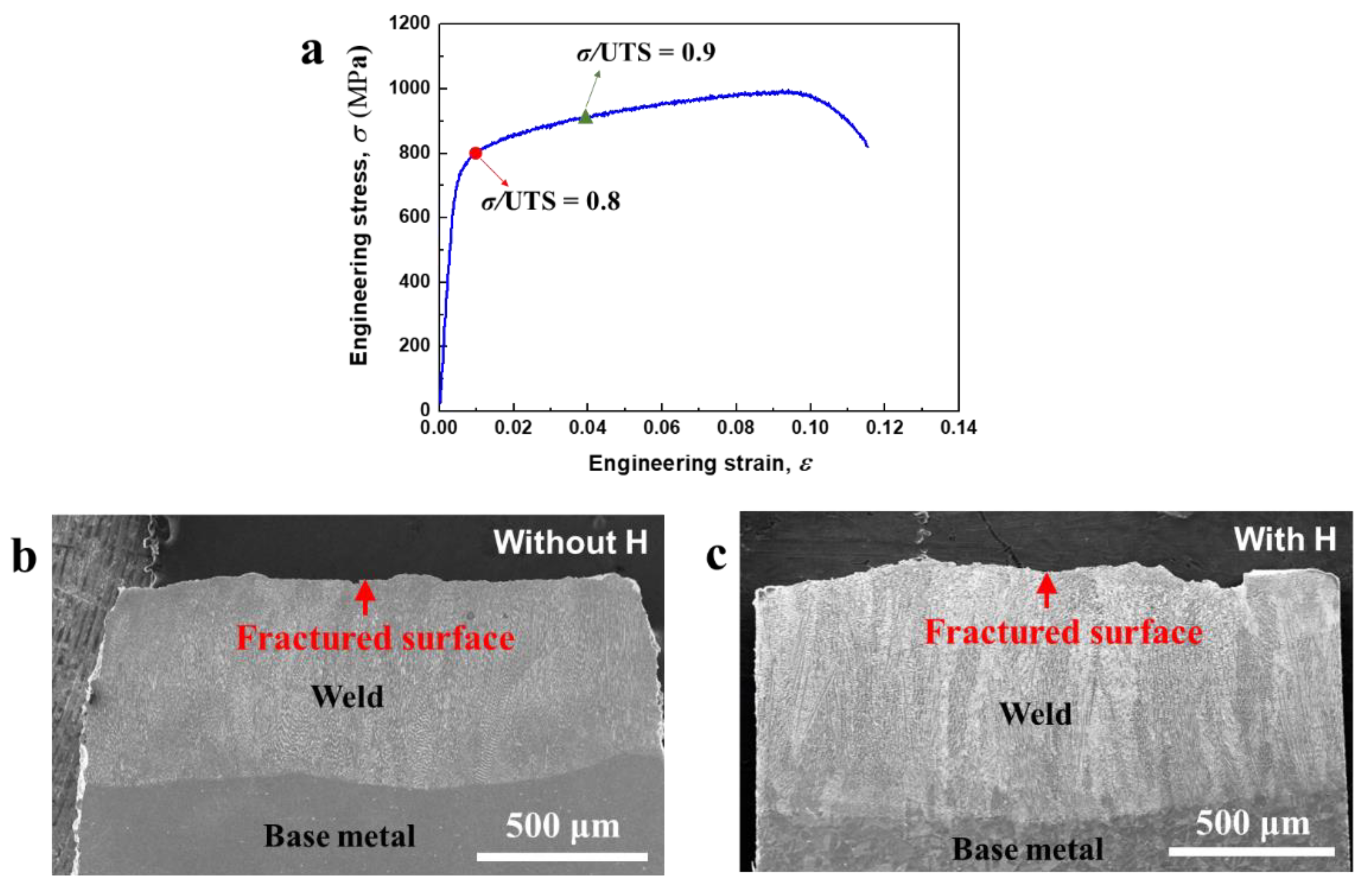
2. Experiments
3. Results
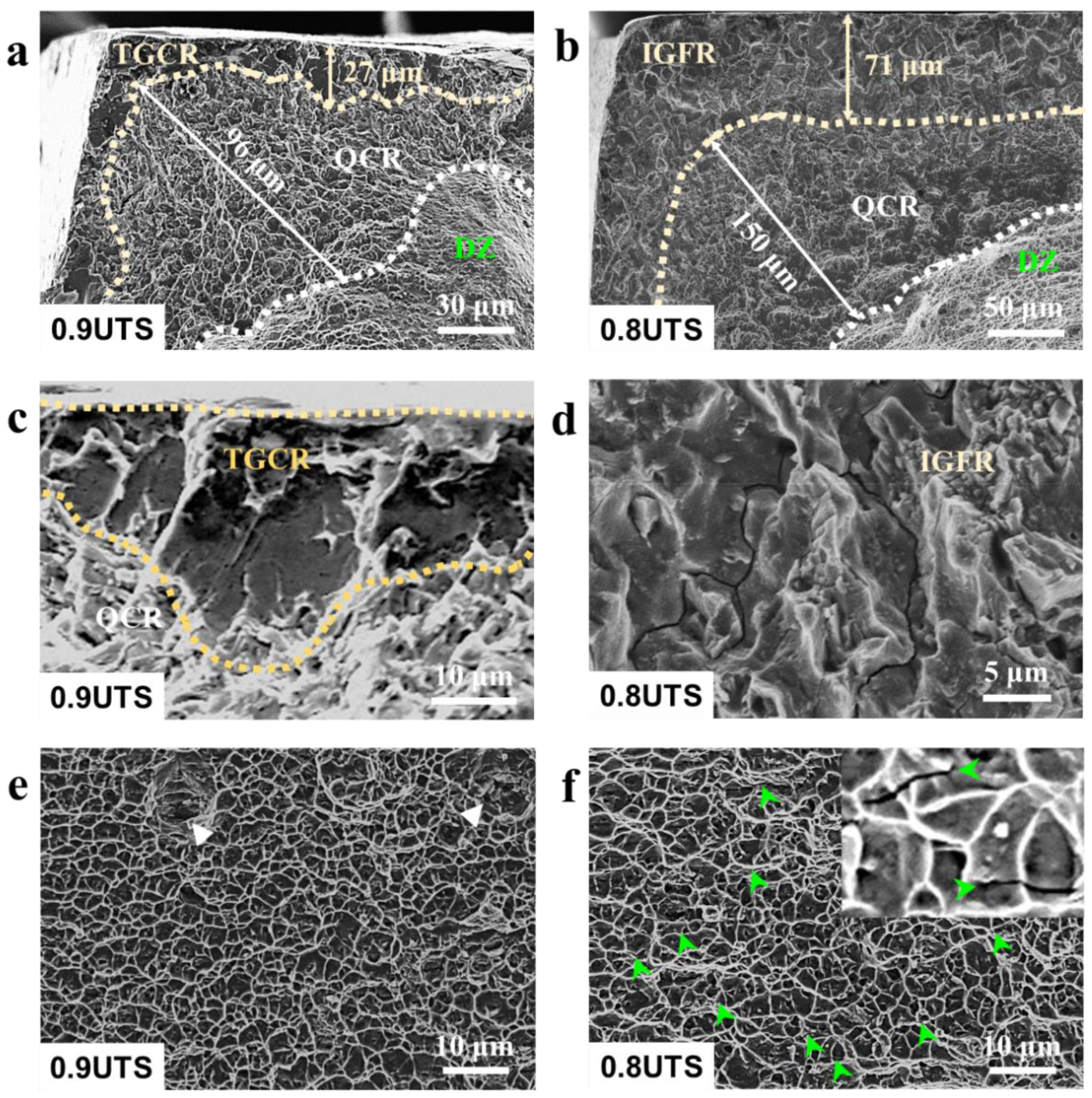
3.1. Marginal Hydrogen-Induced Brittle Fracture Zone
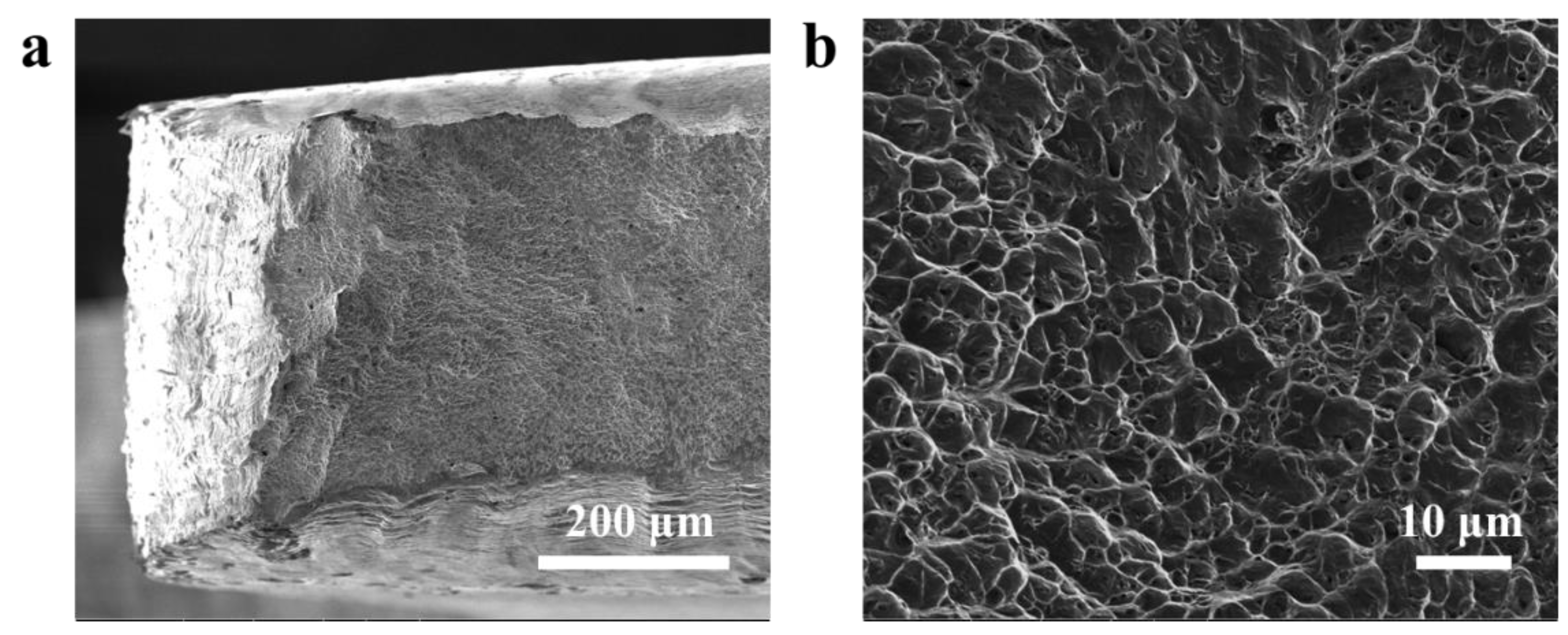
3.2. Central Dimple Zone
4. Discussions
5. Conclusions
Author Contributions
Funding
Institutional Review Board Statement
Informed Consent Statement
Data Availability Statement
Conflicts of Interest
References
- Zhong, W.; Cai, Y.; Tománek, D. Computer simulation of hydrogen embrittlement in metals. Nature 1993, 362, 435–437. [Google Scholar] [CrossRef]
- Tiegel, M.C.; Martin, M.L.; Lehmberg, A.K.; Deutges, M.; Borchers, C.; Kirchheim, R. Crack and blister initiation and growth in purified iron due to hydrogen loading. Acta Mater. 2016, 115, 24–34. [Google Scholar] [CrossRef]
- Kim, W.K.; Koh, S.U.; Yang, B.Y.; Kim, K.Y. Effect of environmental and metallurgical factors on hydrogen induced cracking of HSLA steels. Corros. Sci. 2008, 50, 3336–3342. [Google Scholar] [CrossRef]
- Zan, N.; Ding, H.; Guo, X.F.; Tang, Z.Y.; Bleck, W. Effects of grain size on hydrogen embrittlement in a Fe-22Mn-0.6C TWIP steel. Int. J. Hydrog. Energy 2015, 40, 10687–10696. [Google Scholar] [CrossRef]
- Hoyos, J.J.; Masoumi, M.; Pereira, V.F.; Tschiptschin, A.P.; Paes, M.T.P.; Avila, J.A. Influence of hydrogen on the microstructure and fracture toughness of friction stir welded plates of API 5L X80 pipeline steel. Int. J. Hydrog. Energy 2019, 44, 23458–23471. [Google Scholar] [CrossRef]
- Saini, N.; Pandey, C.; Mahapatra, M.M. Effect of diffusible hydrogen content on embrittlement of P92 steel. Int. J. Hydrog. Energy 2017, 42, 17328–17338. [Google Scholar] [CrossRef]
- Li, X.B.; Gao, M.; Li, H.Z.; Xing, W.W.; Zhang, L.; Shu, L.; Zhao, X.J.; Ma, Y.C.; Liu, K. Effect of residual hydrogen content on the tensile properties and crack propagation behavior of a type 316 stainless steel. Int. J. Hydrog. Energy 2019, 44, 25054–25063. [Google Scholar] [CrossRef]
- Wang, M.Q.; Akiyama, E.; Tsuzaki, K. Determination of the critical hydrogen concentration for delayed fracture of high strength steel by constant load test and numerical calculation. Corros. Sci. 2006, 48, 2189–2202. [Google Scholar] [CrossRef]
- Najam, H.; Koyama, M.; Bal, B.; Akiyama, E.; Tsuzaki, K. Strain rate and hydrogen effects on crack growth from a notch in a Fe-high-Mn steel containing 1.1wt% solute carbon. Int. J. Hydrog. Energy 2020, 45, 1125–1139. [Google Scholar] [CrossRef]
- Momotani, Y.; Shibata, A.; Terada, D.; Tsuji, N. Effect of strain rate on hydrogen embrittlement in low-carbon martensitic steel. Int. J. Hydrog. Energy 2017, 42, 3371–3379. [Google Scholar] [CrossRef]
- Zhou, C.S.; Song, Y.Y.; Shi, Q.Y.; Hu, S.Y.; Zheng, J.Y.; Xu, P.; Zhang, L. Effect of pre-strain on hydrogen embrittlement of metastable austenitic stainless steel under different hydrogen conditions. Int. J. Hydrog. Energy 2019, 44, 26036–26048. [Google Scholar] [CrossRef]
- Fu, H.; Wang, W.; Zhao, H.Y.; Jin, F.; Li, J.X. Study of hydrogen-induced delayed fracture in high-Mn TWIP/TRIP steels during in situ electrochemical hydrogen-charging: Role of microstructure and strain rate in crack initiation and propagation. Corros. Sci. 2020, 162, 108191. [Google Scholar] [CrossRef]
- Liu, H.W. Hydrogen assisted intergranular cracking in steels. Eng. Fract. Mech. 2011, 78, 2563–2571. [Google Scholar] [CrossRef]
- Robertson, I.M.; Sofronis, P.; Nagao, A.; Martin, M.L.; Wang, S.; Gross, D.W.; Nygren, K.E. Hydrogen Embrittlement Understood. Metall. Mater. Trans. B 2015, 46, 1085–1103. [Google Scholar] [CrossRef]
- Li, H.; Venezuela, J.; Qian, Z.; Zhou, Q.J.; Shi, Z.M.; Yan, M.; Knibbe, R.; Zhang, M.X.; Dong, F.T.; Atrens, A. Hydrogen fracture maps for sheared-edge-controlled hydrogen-delayed fracture of 1180 MPa advanced high-strength steels. Corros. Sci. 2021, 48, 109360. [Google Scholar] [CrossRef]
- Rho, B.S.; Hong, H.U.; Nam, S.W. Analysis of the intergranular cavitation of Nb-A286 alloy in high temperature low cycle fatigue using EBSD technique. Scr. Mater. 2000, 43, 167–173. [Google Scholar] [CrossRef]
- Zhao, M.J.; Guo, Z.F.; Rong, L.J. Effect of boron on the microstructure, mechanical properties and hydrogen performance in a modified A286. Mater. Sci. Eng. A 2010, 527, 5844–5851. [Google Scholar] [CrossRef]
- Brooks, J.A.; Thompson, A.W. Microstructure and hydrogen effects on fracture in the alloy A-286. Metall. Mater. Trans. A 1993, 24, 1983–1991. [Google Scholar] [CrossRef]
- Li, Y.Y.; Fan, C.G.; Rong, L.J.; Yan, D.S.; Li, X.Y. Hydrogen embrittlement resistance of austenitic alloys and aluminium alloys. Acta. Metall. Sin. 2010, 46, 1335–1346. [Google Scholar] [CrossRef]
- Nakkalil, R.; Richards, N.L.; Chaturvedi, M.C. Fusion zone microstructure of electron beam welded incoloy 903. Scr. Metall. Mater. 1992, 26, 545–550. [Google Scholar] [CrossRef]
- Richards, N.L.; Nakkalil, R.; Chaturvedi, M.C. The influence of electron-beam welding parameters on heat-affected-zone microfissuring in INCOLOY 903. Metall. Mater. Trans. A 1994, 25, 1733–1745. [Google Scholar] [CrossRef]
- Tschegg, E.K.; Tauschitz, C.; Stanzl, S.E. The fatigue crack growth behavior of electron-beam welded a286 superalloy. Metall. Mater. Trans. A 1982, 13, 1483–1489. [Google Scholar] [CrossRef]
- Mei, Y.P.; Liu, Y.C.; Liu, C.X.; Li, C.; Yu, L.M.; Guo, Q.Y.; Li, H.J. Effect of base metal and welding speed on fusion zone microstructure and HAZ hot-cracking of electron-beam welded Inconel 718. Mater. Des. 2016, 89, 964–977. [Google Scholar] [CrossRef]
- Pereira, P.A.S.; Franco, C.S.G.; Filho, J.L.M.G.; Santos, D.S.d. Hydrogen effects on the microstructure of a 2.25Cr–1Mo–0.25 V steel welded joint. Int. J. Hydrog. Energy 2015, 40, 17136–17143. [Google Scholar] [CrossRef]
- Zafra, A.; Belzunce, J.; Rodríguez, C.; Fernández-Pariente, I. Hydrogen embrittlement of the coarse grain heat affected zone of a quenched and tempered 42CrMo4 steel. Int. J. Hydrog. Energy 2020, 45, 16890–16908. [Google Scholar] [CrossRef]
- Oliveira, J.P.; Crispim, B.; Zeng, Z.; Omori, T.; Fernandes, F.M.B.; Miranda, R.M. Microstructure and mechanical properties of gas tungsten arc welded Cu-Al-Mn shape memory alloy rods. J. Mater. Process. Tech. 2019, 271, 93–100. [Google Scholar] [CrossRef]
- Yang, J.; Oliveira, J.P.; Li, Y.L.; Tan, C.W.; Gao, C.K.; Zhao, Y.X.; Yu, Z.S. Laser techniques for dissimilar joining of aluminum alloys to steels: A critical review. J. Mater. Process. Tech. 2022, 301, 117443. [Google Scholar] [CrossRef]
- Oliveira, J.P.; Shamsolhodaei, A.; Shen, J.J.; Lopes, J.G.; Gonçalves, R.M. Improving the ductility in laser welded joints of CoCrFeMnNi high entropy alloy to 316 stainless steel. Mater. Des. 2022, 219, 110717. [Google Scholar] [CrossRef]
- Chen, S.H.; Zhao, M.J.; Liang, H.; Rong, L.J. Microstructure and Mechanical Properties of Electron Beam Welded Alloy J75. J. Mater. Sci. Technol. 2014, 30, 493–498. [Google Scholar] [CrossRef]
- Chen, S.H.; Hu, H.L.; Zhao, M.J.; Rong, L.J. Effect of post-weld aging treatment on the precipitation and mechanical behavior of Fe-Ni based alloy weldment. Mater. Sci. Eng. A 2018, 718, 363–370. [Google Scholar] [CrossRef]
- Yan, Y.J.; Yan, Y.; He, Y.; Li, J.X.; Su, Y.J.; Qiao, L.J. The mechanism of precipitation strengthening in Fe–Ni austenitic alloy electron beam weldment. Mater. Sci. Eng. A 2015, 630, 85–89. [Google Scholar] [CrossRef]
- Yan, Y.J.; Yan, Y.; He, Y.; Li, J.X.; Su, Y.J.; Qiao, L.J. Hydrogen-induced cracking and service safety evaluation for precipitation strengthened austenitic stainless steel as hydrogen storage tank. Int. J. Hydrog. Energy 2014, 39, 17921–17928. [Google Scholar] [CrossRef]
- Xu, J.; Sun, X.K.; Chen, W.X.; Li, Y.Y. Hydrogen permeation and diffusion in iron-base superalloys. Acta Metall. Mater. 1993, 41, 1455–1459. [Google Scholar] [CrossRef]
- Liu, Y.; Wang, M.Q.; Liu, G.Q. Hydrogen trapping in high strength martensitic steel after austenitized at different temperatures. Int. J. Hydrog. Energy 2013, 38, 14364–14368. [Google Scholar] [CrossRef]
- Phaniraj, M.P.; Kim, H.J.; Suh, J.Y.; Shim, J.H.; Park, S.J.; Lee, T.H. Hydrogen embrittlement in high interstitial alloyed 18Cr10Mn austenitic stainless steels. Int. J. Hydrog. Energy 2015, 40, 13635–13642. [Google Scholar] [CrossRef]
- Chen, S.H.; Zhao, M.J.; Rong, L.J. Role of gamma’ characteristic on the hydrogen embrittlement susceptibility of Fe-Ni-Cr alloys. Corros. Sci. 2015, 101, 75–83. [Google Scholar] [CrossRef]
- Zhang, Z.B.; Moore, K.L.; McMahon, G.; Morana, R.; Preuss, M. On the role of precipitates in hydrogen trapping and hydrogen embrittlement of a nickel-based superalloy. Corros. Sci. 2019, 146, 58–69. [Google Scholar] [CrossRef]
- Cheng, X.Y.; Zhang, H.X. A new perspective on hydrogen diffusion and hydrogen embrittlement in low-alloy high strength steel. Corros. Sci. 2020, 174, 108800. [Google Scholar] [CrossRef]
- Dong, L.S.; Wang, S.Z.; Wu, G.L.; Gao, J.H.; Zhou, X.Y.; Wu, H.H.; Mao, X.P. Application of atomic simulation for studying hydrogen embrittlement phenomena and mechanism in iron-based alloys. Int. J. Hydrog. Energy 2022, 47, 20288–20309. [Google Scholar] [CrossRef]
- Sofronis, P.; Birnbaum, H.K. Mechanics of the hydrogen-dislocation-impurity interactions—I. Increasing shear modulus. J. Mech. Phys. Solids 1995, 43, 49–90. [Google Scholar] [CrossRef]
- Robertson, I.M.; Birnbaum, H.K.; Sofronis, P. Chapter 91 Hydrogen Effects on Plasticity. Dislocat. Solids 2009, 15, 249–293. [Google Scholar] [CrossRef]
- Pundt, A.; Kirchheim, R. Hydrogen in metals: Microstructural aspects. Annu. Rev. Mater. Res. 2006, 36, 555–608. [Google Scholar] [CrossRef]
- Robertson, I.M.; Birnbaum, H.K. An HVEM study of hydrogen effects on the deformation and fracture of nickel. Acta Metall. 1986, 34, 353–366. [Google Scholar] [CrossRef]
- Neeraj, T.; Srinivasan, R.; Li, J. Hydrogen embrittlement of ferritic steels: Observations on deformation microstructure, nanoscale dimples and failure by nanovoiding. Acta Mater. 2012, 60, 5160–5171. [Google Scholar] [CrossRef]
- Martin, M.L.; Fenske, J.A.; Liu, G.S.; Sofronis, P.; Robertson, I.M. On the formation and nature of quasi-cleavage fracture surfaces in hydrogen embrittled steels. Acta Mater. 2011, 59, 1601–1606. [Google Scholar] [CrossRef]
- Nibur, K.A.; Somerday, B.P.; Balch, D.K.; Marchi, C.S. The role of localized deformation in hydrogen-assisted crack propagation in 21Cr–6Ni–9Mn stainless steel. Acta Mater. 2009, 57, 3795–3809. [Google Scholar] [CrossRef]
- Zhou, X.Y.; Zhu, J.H.; Wu, Y.; Yang, X.S.; Lookman, T.; Wu, H.H. Machine learning assisted design of FeCoNiCrMn high-entropy alloys with ultra-low hydrogen diffusion coefficients. Acta Mater. 2022, 224, 117535. [Google Scholar] [CrossRef]
- Oudriss, A.; Creus, J.; Bouhattate, J.; Conforto, E.; Berziou, C.; Savall, C.; Feaugas, X. Grain size and grain-boundary effects on diffusion and trapping of hydrogen in pure nickel. Acta Mater. 2012, 60, 6814–6828. [Google Scholar] [CrossRef]
- Chen, Y.S.; Lu, H.Z.; Liang, J.T.; Rosenthal, A.; Liu, H.W.; Sneddon, G.; McCarroll, I.; Zhao, Z.Z.; Li, W.; Guo, A.M.; et al. Observation of hydrogen trapping at dislocations, grain boundaries, and precipitates. Science 2020, 367, 171–175. [Google Scholar] [CrossRef]
- Alvaro, A.; Jensen, I.T.; Kheradmand, N.; Løvvik, O.M.; Olden, V. Hydrogen embrittlement in nickel, visited by first principles modeling, cohesive zone simulation and nanomechanical testing. Int. J. Hydrog. Energy 2015, 40, 16892–16900. [Google Scholar] [CrossRef]
- Li, X.F.; Zhang, J.; Akiyama, E.; Wang, Y.F.; Li, Q.Z. Microstructural and crystallographic study of hydrogen-assisted cracking in high strength PSB1080 steel. Int. J. Hydrog. Energy 2018, 43, 17898–17911. [Google Scholar] [CrossRef]
- Okada, K.; Shibata, A.; Takeda, Y.; Tsuji, N. Crystallographic feature of hydrogen-related fracture in 2Mn-0.1C ferritic steel. Int. J. Hydrog. Energy 2018, 43, 11298–11306. [Google Scholar] [CrossRef]
- Kim, K.S.; Kang, J.H.; Kim, S.J. Carbon effect on hydrogen diffusivity and embrittlement in austenitic stainless steels. Corros. Sci. 2020, 180, 109226. [Google Scholar] [CrossRef]
- Zhou, X.Y.; Zhu, J.H.; Wu, H.H.; Yang, X.S.; Wang, S.Z.; Mao, X.P. Unveiling the role of hydrogen on the creep behaviors of nanograined α-Fe via molecular dynamics simulations. Int. J. Hydrog. Energy 2021, 46, 9613–9629. [Google Scholar] [CrossRef]


| Element | Mn | C | Si | V | Al | Mo | Ti | Cr | Ni | Fe |
|---|---|---|---|---|---|---|---|---|---|---|
| Content | Minimize | ≤0.02 | 0.2 | 0.25 | 0.3 | 1.3 | 2.1 | 15 | 31 | Balance |
Publisher’s Note: MDPI stays neutral with regard to jurisdictional claims in published maps and institutional affiliations. |
© 2022 by the authors. Licensee MDPI, Basel, Switzerland. This article is an open access article distributed under the terms and conditions of the Creative Commons Attribution (CC BY) license (https://creativecommons.org/licenses/by/4.0/).
Share and Cite
Yan, Y.; Zhang, Y.; Zhao, L.; Chen, Y.; Cao, R.; Wu, H.; He, Y.; Yan, Y.; Qiao, L. Effect of Applied Tensile Stress on Hydrogen-Induced Delayed Fracture Mode of Fe-Ni-Cr Austenitic Alloy Weldment. Metals 2022, 12, 1614. https://doi.org/10.3390/met12101614
Yan Y, Zhang Y, Zhao L, Chen Y, Cao R, Wu H, He Y, Yan Y, Qiao L. Effect of Applied Tensile Stress on Hydrogen-Induced Delayed Fracture Mode of Fe-Ni-Cr Austenitic Alloy Weldment. Metals. 2022; 12(10):1614. https://doi.org/10.3390/met12101614
Chicago/Turabian StyleYan, Yingjie, Yukun Zhang, Lixian Zhao, Yongqing Chen, Rui Cao, Honghui Wu, Yang He, Yu Yan, and Lijie Qiao. 2022. "Effect of Applied Tensile Stress on Hydrogen-Induced Delayed Fracture Mode of Fe-Ni-Cr Austenitic Alloy Weldment" Metals 12, no. 10: 1614. https://doi.org/10.3390/met12101614