Article

Effect of Rotational Speed on Static and Fatigue Properties of Rotary Friction Welded Dissimilar AA7075/AA5083 Aluminium Alloy Joints

1
Department of Mechanical and Industrial Engineering, Universitas Gadjah Mada, Yogyakarta 55281, Indonesia
2
Badan Riset dan Inovasi Nasional (BRIN), Serpong 15314, Indonesia
3
National Nuclear Energy Agency of Indonesia (BATAN), Serpong 15314, Indonesia
*
Author to whom correspondence should be addressed.
Metals 2022, 12(1), 99; https://doi.org/10.3390/met12010099
Submission received: 30 November 2021 / Revised: 26 December 2021 / Accepted: 29 December 2021 / Published: 4 January 2022

Abstract

:
In this work, rotary friction welding processes of dissimilar AA7075/AA5083 aluminium alloy rods with the diameter of 15 mm were performed at varying rotational speeds, typically 370 to 2500 rpm. The aim of this research is to improve mechanical properties, in particular, strength and fatigue performance of the weld joints. Several experiments including macro and microstructural examinations, Vickers microhardness measurements, tensile tests, fatigue tests and residual stress measurements were carried out. Results showed that at higher rotational speeds, typically 540 rpm or above, the dissimilar AA7075/AA5083 rotary friction weld joints revealed a static fracture in the AA5083 base metal side, indicating that the joint efficiency is more than 100%. It seemed that the best weld joint was achieved at the rotational speed of 1200 rpm, in which the friction heat was sufficient to form metallurgical bonding without causing excessive flash and burn-off. In such a condition, the fatigue strength of the weld joint was slightly higher than AA5083 base metal, but it was lower than AA7075 base metal. It was confirmed that the crack origin is observed at the interface followed by fatigue crack growth towards AA5083 side, and the growth of crack seemed to be controlled by microstructure and residual stress.

1. Introduction

Over the years, aluminium alloys such as 5xxx series (Al-Mg alloys) and 7xxx series (Al-Zn alloys) have been used for lightweight structures in the transportation industry due to their excellent properties such as high strength-to-weight ratio, acceptable fatigue properties resistance and good machinability [1,2]. AA5083 is the main aluminium alloy of 5xxx series since it finds wide applications such as ship hulls, automobiles and various welded structures exposed to corrosive environment, e.g., offshore oil rigs [3,4]. On the other hand, AA7075 and its 7xxx series are among the principal choices for aircraft structures and automotive applications [5]. In terms of weldability, AA5083 is readily welded by various welding processes [6], and in contrast, AA7075 is considered to be unweldable by fusion welding due to solidification cracking [7]. Therefore, dissimilar metal welding of these two materials seems challenging and it needs an appropriate joining method.
Rotary friction welding (RFW) is a solid-state welding that has gained importance in the manufacturing industry due to its advantages over other joining processes including high reproducibility, short production time and low energy input. In addition, the welding process can be easily automated, and it is feasible for joining dissimilar materials [8,9]. As the name implies, RSW employs rotation to produce friction heat between two contacting surfaces combined with axial force to accomplish friction welding. In such a condition, heat generated during welding seems to be a key factor determining quality of the weld joint. The analysis of heat generation and temperature field during RFW using modeling approach have been reported by several researchers [10,11,12].
In recent years, several research works on RFW have been conducted with the objective of improving the quality of weld joints by considering welding parameters including rotational speed, friction pressure, forging pressure, friction time and forging time. Among these welding parameters, rotational speed has attracted more attention. Etesami et al. [13] have investigated the effect of rotational speed on properties of friction AA2024 aluminium alloy welded joints. According to the researchers, increasing rotational speed can reduce the number of cracks and imperfections accompanied by increasing hardness and tensile strengths. Li et al. [14] have studied characteristics of friction time and friction work as a function of rotational speed. The results show that the friction time and friction work profiles reveal a V-shaped appearance when the minimum values occur at 900 rpm. Subsequently, the work of Uday et al. [15] suggested that an increase in rotational speed increased frictional heat at the interface, resulting in softening of the material and to a greater extent, recrystallization or even intermetallic formation. Therefore, the high quality of RFW joints is produced as the rotational speed is optimised.
In some engineering applications, the use of dissimilar metal weld joints is often necessary for the optimisation of properties such as strength, weight and corrosion. In addition, the welding of dissimilar metals is required when the use of more costly single metal only is limited [16]. During the last few years, extensive studies on dissimilar metal rotary friction welded joints have been conducted with the aim of improving the performance of the weld joints of different materials, some of which include stainless steel-alloy steel [17,18], aluminium alloy–stainless steel [19,20], aluminium alloy–titanium [21,22] and titanium–stainless steel [23].
Fatigue is one of the important design considerations for structures and components which are subjected to cyclic loads in service. Several works have been conducted to study fatigue behaviours of similar and dissimilar metal rotary friction weld joints. Some reports have shown that fatigue behaviours of rotary friction welded 6061 aluminium alloy joints, and the results showed that the fatigue strength of the weld joint was slightly lower than that of the 6061 aluminium alloy base metal and the fracture origin occurred near the weld interface [24,25]. Consistent with these works, Yang et al. [26], who have worked on inertia friction Ni-based superalloy weld joints, showed that fatigue failure of the inertia friction joint was located at the border between weld nugget zone (WNZ) and thermomechanically affected zone (TMAZ), and this location of the fracture could be related to the microhardness differences between TMAZ and WNZ. In the case of dissimilar metal rotary friction weld joints between 304 austenitic stainless steel and 4340 steel, the fatigue limit of the weld joints decreased as the rotational speed was increased due to precipitation of chromium carbides which act as a stress raiser [27].
Recently, Lu et al. [28] have investigated mechanical properties of dissimilar inertia friction welded 7005/5083 aluminium alloy joints with the results showed that the strength of the weld joints increased with increasing rotational speed and according to the researchers, the optimum rotational speed was achieved at 3000 rpm. Unfortunately, further data on fatigue properties of the dissimilar metal rotary friction weld joints between 7xxx and 5xxx series are not yet well documented. Therefore, it is the subject of the present investigation. It is worth noting that joining of these dissimilar alloys using RSW has a potency for engineering applications such as the structural components of vehicles.

2. Materials and Methods
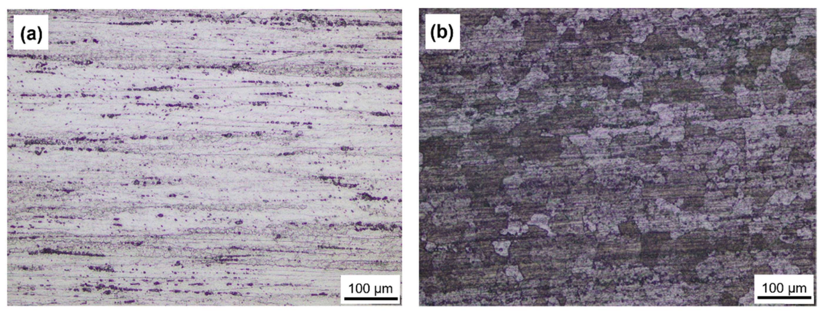
2.1. Materials

The materials used in this study were AA5083 and AA7075 aluminium alloy rods which were treated using H112 and T6, respectively, and their chemical compositions are given in Table 1, whereas the microstructures of the two base metals are shown in Figure 1.
Referring to Figure 1a, it can be seen that the microstructure of the AA7075 is composed of elongated grains parallel to the rolling direction typical of wrought product. Similar microstructural feature is observed in AA5083 in Figure 1b but unlike AA7075, the microstructure of AA5083 reveals coarser grains. The mechanical properties of AA7075 and AA5083 base metals obtained from the measurements with their standards given in brackets are presented in Table 2. Of note is that the tensile tests were conducted in triplicate to ensure reproducibility with the tensile specimens which were prepared according to ASTM E8/E8M-16 standard. The hardness measurements were taken along the centre line of the parallel section of the rods and along the radial direction on the cross section of the rods. Referring to Table 2, it can be seen that the strength and hardness of AA7075 are higher than that of AA5083.

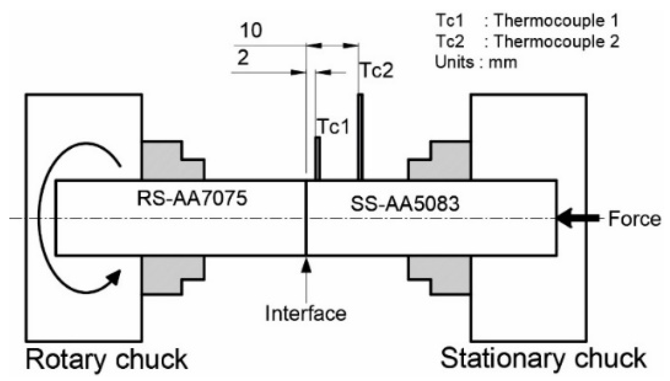
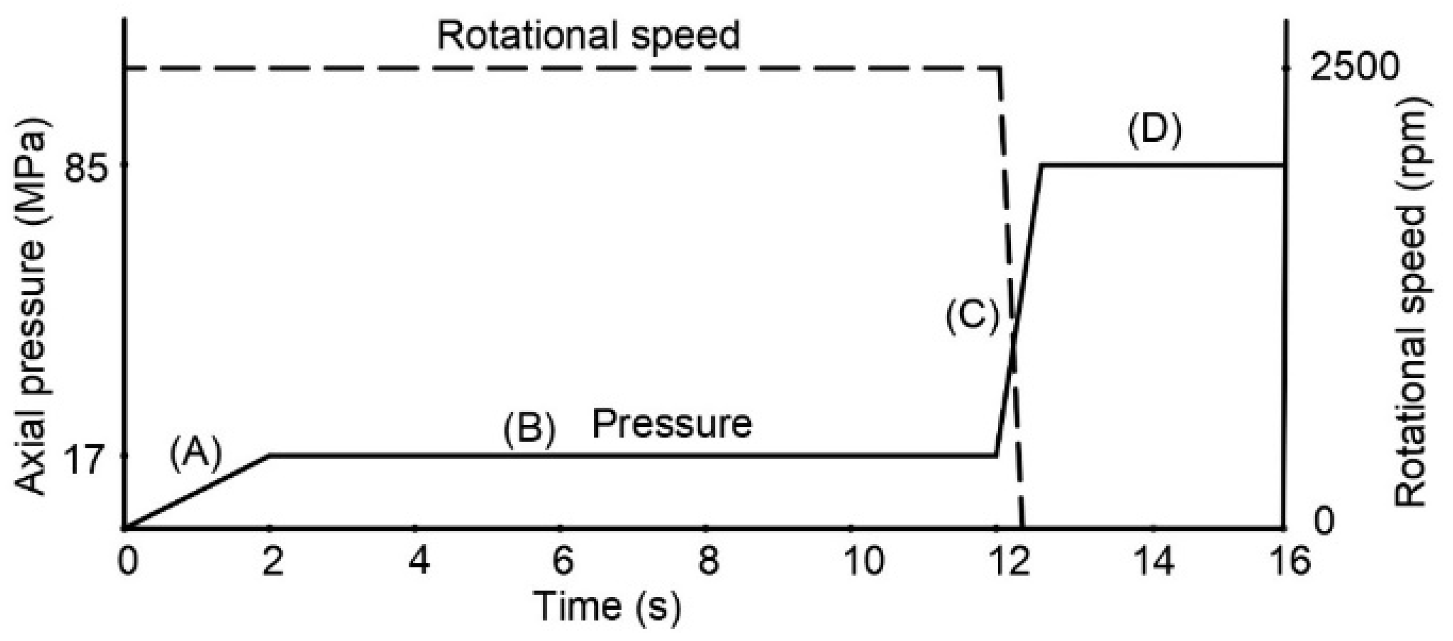
2.2. The Rotary Friction Welding Process

In this work, the rotary friction welding machine was built by modification of a lathe machine. The specimens were machined in the form of a cylindrical rod having 15 mm in diameter and 50 mm in length. The AA5083 cylindrical rod was positioned as stationary side (SS) which was moved axially, whereas the second rod, namely AA7075 acted as rotary side (RS), as shown in Figure 2. The temperature changes during friction welding process were measured by two K-type thermocouples, namely (Tc1) and (Tc2) attached to the AA5083 rod (stationary side) at the initial distances of 2 mm and 10 mm from the interface, respectively.
RFW processes of dissimilar AA7075/AA5083 aluminium alloys were carried out using the RFW steps as shown in Figure 3 and Table 3. The first step of welding process started as the faying surface came into contact with the stationary surface accompanied by a rapid increase in axial pressure from 0 to 17 MPa for 2 s as marked by A in Figure 3 followed by friction stage at a constant pressure of 17 MPa for 10 s (step B). At the end of friction stage, the rotational speed was stopped (step C), and at the same time, the upset pressure of 85 MPa was applied for 4 s (step D), leading to bond formation. The weld thermal cycles and changes in burn-off length as the response parameter were recorded during welding.
In this study, the welding parameters including friction pressure, friction time, forging pressure and forging time were maintained constant, whereas rotational speed was varied at 6 different rotational speeds of 370, 540, 800, 1200, 1700 and 2500 rpm.

2.3. Macro and Microstructures

Macro and microstructural examinations were carried on cross sections of the RFW joints to identify various microstructures present in dynamically recrystallized zone (DRZ), thermomechanically affected zone (TMAZ), heat affected zone (HAZ) and base metals (BM) of both rotary side (RS) and stationary side (SS). The samples were prepared in accordance with standard laboratory techniques, including grinding, polishing and etching. The etchant used was Keller’s reagent, which consisted of 2 mL HF, 3 mL HCl, 5 mL HNO3 and 190 mL water.

2.4. Microhardness Distributions

The Vickers microhardness measurements were conducted to assess the hardness distributions across the RFW joints due to variations in the weld microstructures. The microhardness measurements were taken at the centreline of the welded rods using the load of 100 grf and dwell time of 10 s with centre-to-centre spacing of 500 µm (0.5 mm).

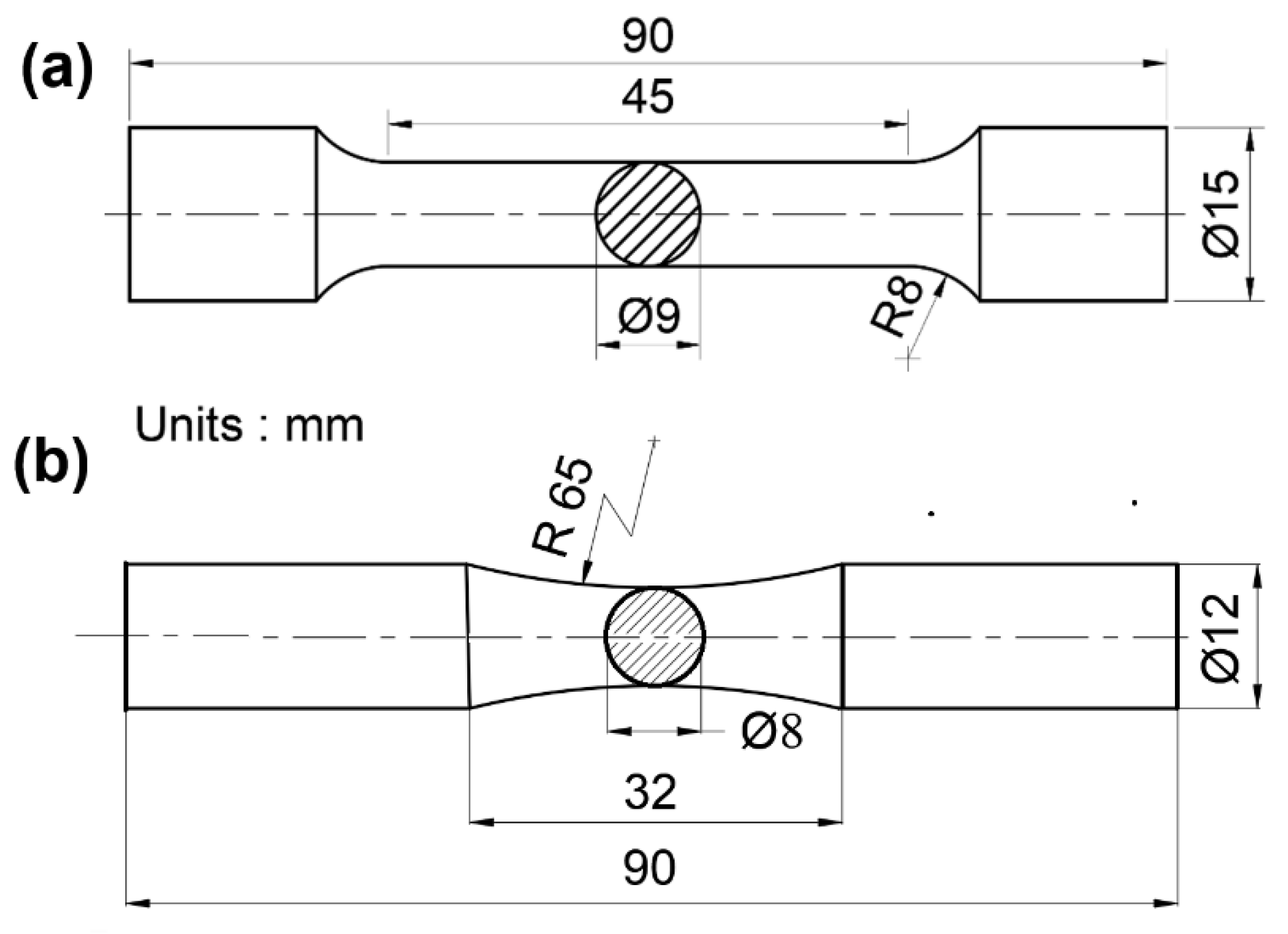
2.5. Mechanical Property Tests (Static and Fatigue Tests)

Tensile tests were carried out using an electromechanical-controlled universal testing machine with the load capacity of 20 tonnes. The tensile specimens were prepared according to ASTM E8/E8M-16 [29] as shown in Figure 4a. From this investigation, ultimate tensile strength (UTS) and yield strength (YS) were obtained.
In this study, rotary friction welded dissimilar AA7075/AA5083 aluminium alloy weld joint produced at rotation speed of 1200 rpm was selected for fatigue tests because at this condition, the strength of the weld joint was maximised with little flash, as will be discussed in the next section. In addition, AA7075 and AA5083 base metals were also fatigue tested as the references. The fatigue tests were carried out using a rotary bending test with the size and geometry of specimens are shown in Figure 4b. The sinusoidal loads (tension-compression) having a frequency of 48 Hz and load ratio, R of –1 were applied at room temperature. From this investigation, S-N curves were created by applying various stress amplitudes which resulted in various fatigue life, Nf. Subsequently, fatigue strength or fatigue limit for each material or weld under study was determined as the specimen achieved 1 × 10⁷ load cycles.
In order to gain comprehensive understanding to the mechanism of crack initiation and crack growth under cyclic loads in rotary friction-welded dissimilar AA5083/AA7050 joints, fractographic study using a low magnification microscope combined with scanning electron microscope (SEM) were also conducted.

2.6. Residual Stress Measurements

The residual stress distributions across the weld joints were measured using neutron diffraction technique at the National Nuclear Energy Agency of Indonesia (BATAN). In this technique, d-spacings were measured based on Bragg’s law in which the monochromatic neutron beam with a wavelength of 1.83375 Å was diffracted on (311) plane at a scattering angle, 2θ of 96.5° whereas the nominal size of gauge volume used was 2 × 2 × 2 mm3. The d-spacings were measured in three principal directions, namely the axial, A (parallel to the rod axis), hoop or tangential, H and radial, R directions. Results of these d-spacing measurements were used to calculate the lattice strains (εi) in each principal direction, as given by:
ε i = d i d o d o
with di and do are strained and strained-free lattice parameters, respectively. The residual stresses (σi) were calculated using Equation (2) as follows [30]:
σ i = E 1 + ν [ ε i + ν ( 1 2 ν ) ( ε A + ε H + ε R ) ]
In this investigation, Young’s modulus, E and Poisson’s ratio, v for high strength aluminium alloys were taken to be 70.2 GPa and 0.35, respectively, as suggested by Pan et al. [31].

3. Results and Discussion

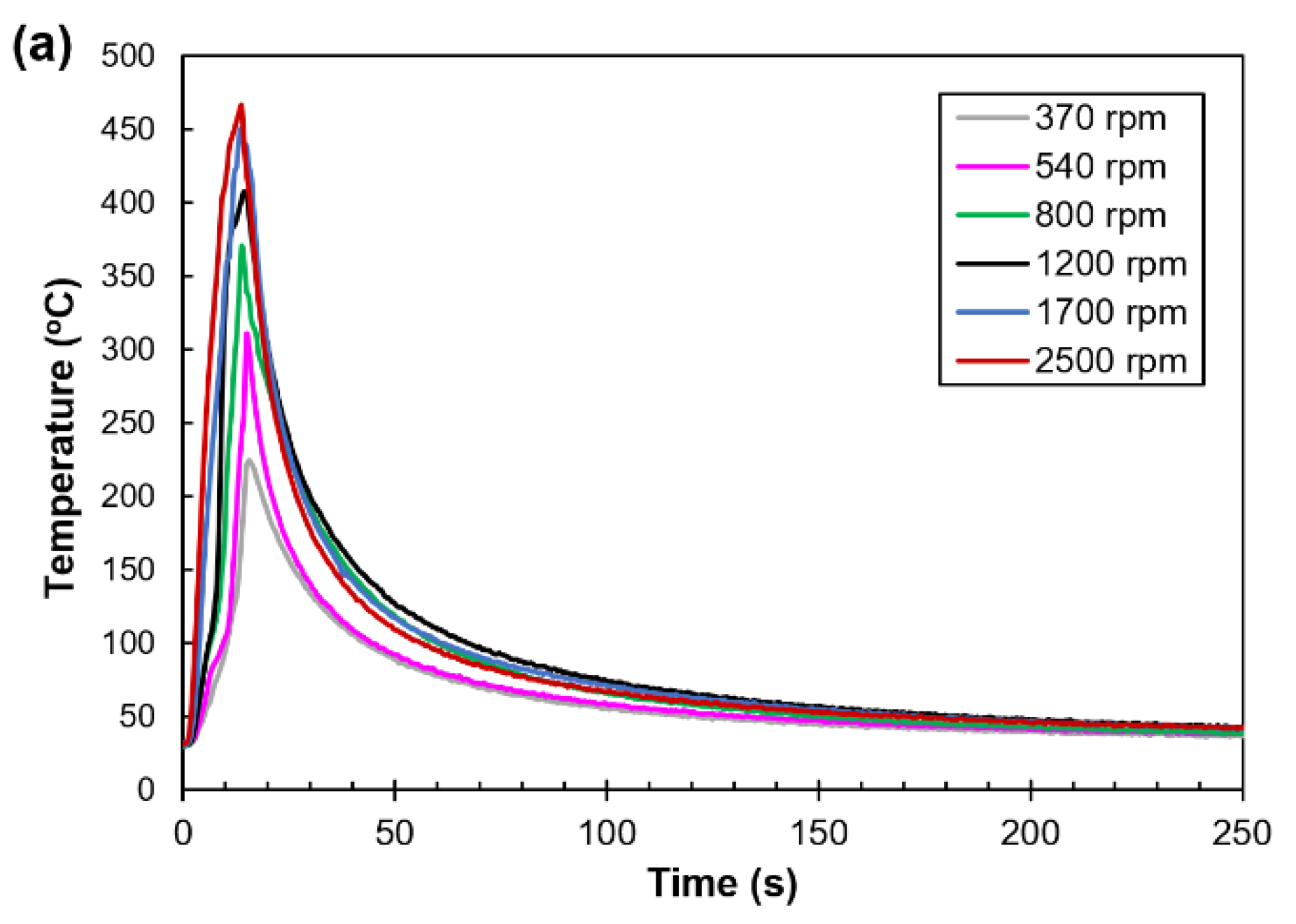
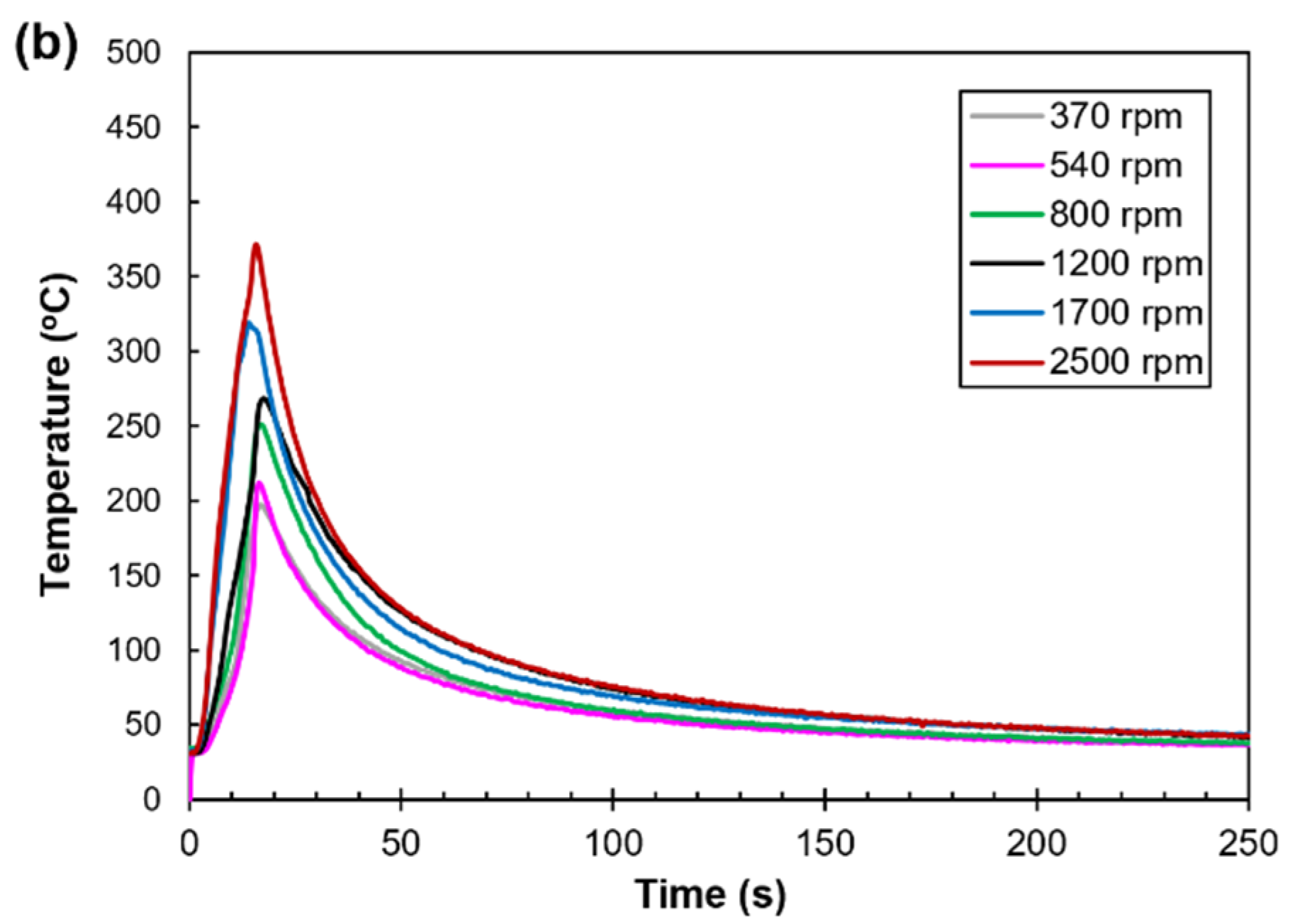
3.1. Weld Thermal Cycles

The understanding of temperature field during welding is important since it determines weld microstructure, residual stress and burn-off length, all of which affect the weld mechanical properties. The weld thermal cycles taken from the distances of 2 and 10 mm, respectively, from the interface are shown in Figure 5. Referring to Figure 5a, it can be seen that each weld thermal cycle shows similar behaviour in which the temperature rises sharply during heating to reach a maximum or peak temperature, Tp followed by a slower cooling rate towards ambient temperature. As the rotational speed is increased then the peak temperature, Tp increases as well accompanied by slower cooling rate. It is worth noting that the peak temperatures, Tp at high rotational speeds, typically 1700 and 2500 rpm recorded by the thermocouple Tc1 are around 451.0 and 466.3 °C, respectively. These temperatures are sufficient to make AA7075 (Al-5.1 wt. % Zn) to reach the supersaturated solid solution (SSSS) condition required for precipitation hardening in the AA7075 side on further cooling to the room temperature. This precipitation hardening will be discussed in the next section. Subsequently, the peak temperature, Tp decreases with increasing distance of x, as indicated by Tc2 (Figure 5b).
Based on these results, the temperature field of the RFW joints may be approached using the analytical solution of heat conduction for a momentary area source in the infinite rod, as given by [32,33]:
T T 0 = Q A ρ c ( 4 π α t ) 1 2 e x 2 4 α t b * t
where T is temperature (K), To is initial temperature (K), Q is heat energy (J), ρ is density (g/mm3), α is thermal diffusivity (mm2/s) which is equal to λ/ρc, λ is thermal conductivity (J/mm.s.K), A is area (mm2), x is distance from the heat source and t is time (s). The term b* in Equation (3) is the heat transfer coefficient with its magnitude given by Equation (4):
b * = ( α C + α r ) P ρ c A
with αc and αr are coefficients of convective heat transfer and heat radiation, respectively, whereas P is the perimeter. Of note is that the heat energy, Q, in Equation (3) is calculated using the following Equation (5) [33]:
Q = k π d n f F
where F is axial force, d is outer diameter of the welded rod, n is the rotation speed, f is the friction coefficient, k is constant with its value depending on the type of power distribution over the cross section of the work piece.

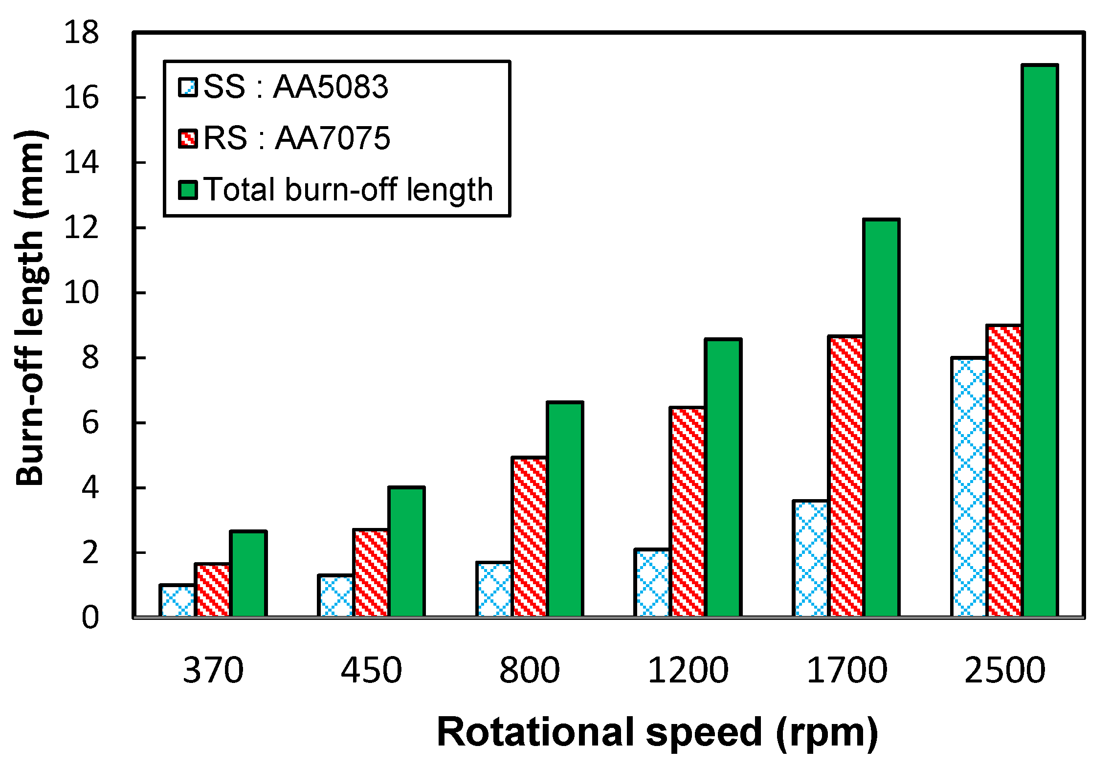
3.2. Burn-Off Length

Figure 6 shows typical dissimilar metal rotary friction welded joints between AA7075 and AA5083 produced using various rotational speeds. It can be seen that an increase in the rotational speed increases burnt-off length accompanied by the formation of more flash metals, especially on the AA7075 side. It seems that increasing the amount of flash metal at a higher rotational speed could be related to the higher friction heat with its magnitude linearly proportional to the rotational speed, according to Equation (4).
Another finding from this investigation is that the burn-off lengths of all weld joints under study are asymmetrical, with the total loss of length in AA7075 being higher than that observed in AA5083, despite the strength of the AA7075 being higher than that of AA5083 at room temperature, as given in Table 2. The plausible explanation is that the thermal conductivity and also thermal diffusivity of AA7075 are lower than that of AA5083 [34] so that the frictional heat is piled up at the AA7075 side during welding, whereas in AA5083, the heat is easily dissipated. As a result, more softening and higher deformation occur in the AA7075 side.
The relationship between burn-off length and rotational speed is shown in Figure 7. It can be seen that at a low rotational speed, typically of 370 rpm, the total burn-off length is around 2.81 mm. Furthermore, the total burn-off length increases steadily as the rotational speed is increased up to 1200 rpm. However, a sharp increase in the total burn-off length occurs as the rotational speed is further increased up to 2500 rpm. In this condition, the frictional heat required for bond formation is excessive, resulting in wastage of base metals as flash. Similar behaviours are observed in the burn-off lengths of the AA7075 rotary side (RS) and the AA5083 stationary side (SS).

3.3. Macro and Microstructure

The macrostructures of all rotary friction welded dissimilar AA7075/AA5083 joints with AA7075 and AA5083 rods are located in rotary side (RS) and stationary side (SS) sides, respectively, are shown in Figure 8. It can be seen that at low rotational speeds, typically of 370 and 540 rpm, large interfaces having a double convex shape are formed and low flash metals are observed. In addition, some weld defects in the form of incomplete bonding are observed in both weld joints. As the rotational speed is increased up to 1200 rpm, the interface tends to be thin and flat with more flashes preferentially formed at the AA7075 side. On further increase in rotational speed up to 1700 rpm or more, the interface becomes very thin, and it is bent towards the AA5083 side, resulting in a single convex shape with excessive flash materials, especially at the AA7075 side. It seems that the thickness and shape of interfaces and also flashes could be linked to the rotational speed which determines friction heat required for bond formation. The present investigation has confirmed that increasing rotational speed increases friction heat, hence making the edges of the weld joint plastically free flowing, and under upset pressure, more interface materials are extruded out of the weld joint as flashes.
Microstructures of the dissimilar AA7075/AA5083 rotary friction welded joints at interface under various rotational speeds taken from the centre line position are shown in Figure 9. Referring to Figure 9, it can be seen that the microstructures of TMAZ for all weld joints consist of fine elongated grains parallel to the interface. In addition, the grains of TMAZ in AA7075 rotary side (RS) are coarser than that of TMAZ at the 5083 stationary side (SS) due to heat accumulation at the 7075 side, which causes severe grain growth of recrystallized grains. However, in the case of high rotational speed, typically 2500 rpm, the grains at TMAZ of 7075 side become finer. This grain refinement probably resulted from the recrystallised grains which are shattered by severe plastic deformation before the growth up. These microstructural examinations are consistent with the work of Li et al. [35].
Referring to Figure 9, it can be seen that the width of DRZs decreases as the rotational speed increases consistent with the previous work which shows that narrow DRZs are associated with higher burn-off length due to higher rotational speed [36]. Another microstructural feature observed in Figure 9 is the presence of very fine grains in DRZs. The magnified DRZ microstructure taken from the weld joint produced at the rotational speed of 1200 rpm is shown in Figure 10. It can be seen that the microstructure of the DRZ at interface exhibits fine equiaxed grains as a result of dynamic recrystallisation under combined effect of friction heat and axial force during welding. The presence of the fine-grained microstructure in DRZ is beneficial because it provides high strength and also hardness according to the Hall–Petch relationship.

3.4. Microharness Distributions of the RFW Joints

Microhardness distributions across the rotary friction weld joints taken at the centreline of the welded rods are shown in Figure 11. It can be seen that the hardness profiles of the weld joints in AA7075 (rotary side) and AA5083 (stationary side) are asymmetrical due to differences in metallurgical properties and strengthening mechanism of the two aluminium alloys. The average hardness values of AA7075 and AA5083 base metals are around 175 Hv and 96 Hv, respectively, whereas the high hardness region is observed at the DRZ region, where its maximum hardness occurs at the interface for all weld joints under study. It seems that the high hardness in DRZ is associated with its fine grain structure as a result of recrystallisation under forging (axial force). On the other hand, TMAZ at the AA7075 side shows a significant increase in the hardness than TMAZ at the AA5083 side, suggesting that the strengthening mechanism of TMAZ in AA7075 is associated with combined effect of strain hardening by axial force and re-precipitation whereas in TMAZ at AA5083, the strengthening mechanism takes place by strain hardening only. This investigation also reveals that increasing rotational speed increases the hardness of TMAZ at the AA7075 side until the high values of hardness are achieved at the rotation speed of 1700 rpm. Furthermore, the hardness degrades as the rotational speed is further increased up to 2500 rpm.
Changes in hardness may be explained based on principles of precipitation hardening. It seems that as the rotational speed is increased, much friction heat is piled up at the AA7075 side during welding, hence resulting in re-precipitation in TMAZ at AA7075, which increases the hardness. It has been reported [37] that the sequence of precipitation reactions that occurs in AA7075 aluminium alloy is given by the following reactions: SSSS→GP zone→metastable η’(Mg(Zn,Al,Cu)2)→stable η(MgZn2). Based on this precipitation reaction, the high hardness is associated with the formation of finer precipitates (η’) or θ”/θ’ phases for AA2xxx which are coherent and semi-coherent with the aluminum matrix [38]. However, as the friction heat is very high at the rotational speed of 2500 rpm, coarsening and dissolution of η (MgZn2) occur leading to loss of hardness in TMAZ of AA7075.

3.5. Tensile Strengths

Figure 12 shows results of tensile strengths given in ultimate tensile strength (UTS) and yield strength (YS) as a function of rotational speed. It is worth noting that except weld joint produced by a low rotational speed of 370 rpm, all weld joints under study are found to fracture in the AA5083 base metal region with their strengths are relatively the same indicating that the joint efficiency defined as the ratio of the strength of weld joint to that of its base metal is higher than 100%. It seems that a low rotation speed of 370 rpm is not sufficient to generate friction heat required for bond formation. However, as the rotational speed is increased above 370 rpm, the bond is completely formed resulting in high strength weld joints. As a consequence, the location of fracture is shifted from the weld region to the AA5083 base metal. These results are consistent with the hardness distribution in Figure 11 in which static fracture occurs in the region with the lowest hardness, i.e., AA5083 base metal.

3.6. Residual Stress

The rotary friction welded dissimilar AA7075/AA5083 joint produced using the rotational speed of 1200 rpm is selected for this study since it has high strength without excessive flash. The distributions of residual stresses in three directions, namely axial stress, hoop stress and radial stress are shown in Figure 13. In general, the residual stress profiles in three directions show similar behaviours in which the residual stresses in the DRZ region and its surrounding area are compressive with the minimum values of −154.0 MPa, −122.0 MPa and −41.6 MPa are observed at the interface for radial, axial and hoop stresses, respectively. Furthermore, the compressive residual stresses in the DRZ region and its adjacent area are balanced by tensile residual stresses outside the DRZ to maintain static equilibrium hence forming M-shaped profile. It seems that the compressive residual stresses present at DRZ and its adjacent area are associated with axial forces applied during weld formation. Another behaviour observed in this investigation is that the residual stress profiles of the dissimilar AA7075/AA5083 metal weld joints are asymmetrical, with higher tensile residual stresses are formed in AA7075 base metal at the distance of 4 to 12 mm away from the weld centreline. This region has lower hardness compared with the initial hardness of AA7075 as shown in Figure 11. This discovery seems to suggest that the regions outside DRZ having lower hardness are associated with tensile residual stresses and in contrast, the high hardness in DRZ could be linked to compressive residual stress. The possible correlation between hardness, residual stress and fatigue properties in the weld joints were previously reported by James et al. [39]. Of note is that all residual stresses measured along the axial axis of the dissimilar AA7075/AA5083 welded joints are lower than the yield stress of the corresponding base metals.

3.7. Fatigue Behaviours

Figure 14 shows S–N curves of the dissimilar AA7075/AA5083 metal weld joint produced using a rotational speed of 1200 rpm with its base metals, namely AA7075 and AA5083 are also used as the references. As commonly observed in aluminium alloys, all S-N curves do not reveal a well-defined endurance limit below which fatigue failure does not occur. Therefore, fatigue strength or fatigue limit used in this study is determined as the strength at the number of cycles of 107 cycles [40]. Referring to Figure 14, it can be seen that the fatigue strength of the weld joint is around 116.5 MPa which is slightly higher than that of AA5083 base metal but in comparison with AA7075 base metal, the fatigue life of the weld joint is 1.59 times lower.
The mechanism of fatigue and some aspects of the fatigue phenomenon are better understood using optical and SEM fractographic methods as shown in Figure 15. For this reason, the weld joint after fatigue test at the applied stress, σf of 137 MPa and the number of cycles, Nf of 6.7 × 10⁵ cycles is selected for this fractographic study because this weld is categorised as high cycle fatigue which is the more common case in engineering practice. Referring to Figure 15a, it can be seen that the fatigue failure seems to occur by the growth of a single fatigue crack with three distinct regions are clearly seen, namely crack origin, fatigue crack growth and final failure regions. Further examination on the fracture surface as shown in Figure 15b shows that the fatigue crack nucleus is initiated at the interface in DRZ. It seems probably that this crack origin could be linked to the heterogeneity of the material in terms of microstructure and microhardness at the interface which reflects the stress concentration factor (Kt) as suggested by Yang et al. [26]. Subsequently, the crack continues to grow from DRZ towards TMAZ of AA5083 side. Apparently, this TMAZ region of AA5083 side provides easy path for the growing crack. This is because the mechanical properties (hardness and strength) of AA5083 are lower than that of AA7075. It seems that better fatigue performance of the age-hardened AA7075 found in this study is associated with the presence of fine precipitates which are dispersed uniformly [41]. In addition, the residual stresses present outside DRZ region, i.e., TMAZ and base metal are tensile as shown in Figure 13 and these tensile residual stresses can cause the fatigue crack growth rate to increase [42]. This is because the total stress acting in these regions is the sum of external stress and residual stress. Accordingly, tensile stress can magnify the total stress and in contrast, compressive residual stress reduces the total stress.
Figure 15c shows SEM fractograph taken from the region marked A in Figure 15a. It can be seen that the fracture surface appears to be cleavage fracture in which the fatigue crack propagates across fine equiaxed grains. In addition, Figure 15c also reveals the presence of striations typical of fatigue fracture. Further SEM examination on the final fracture region marked B in Figure 15a is shown in Figure 15d. It can be seen that striations no longer exist, and the fracture surface is marked by the presence of dimples or microvoids which are commonly observed in ductile fracture surfaces.

4. Conclusions

The present investigation has endeavoured to study effects of rotational speed on microstructure, strength and fatigue behaviours of rotary friction dissimilar AA7053/AA5083 weld joints, and the conclusions that can be drawn are summarised as follows:
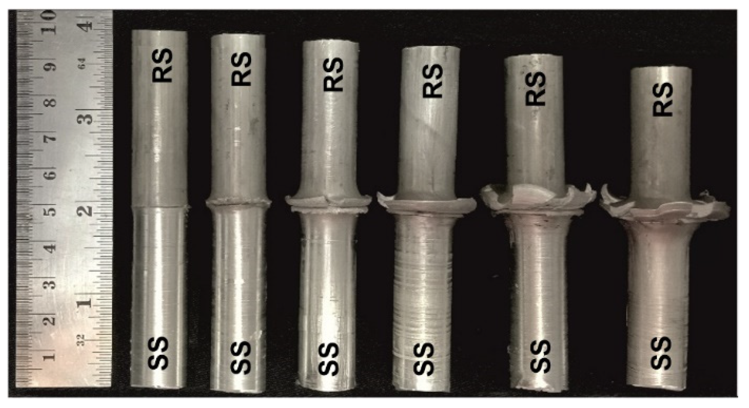
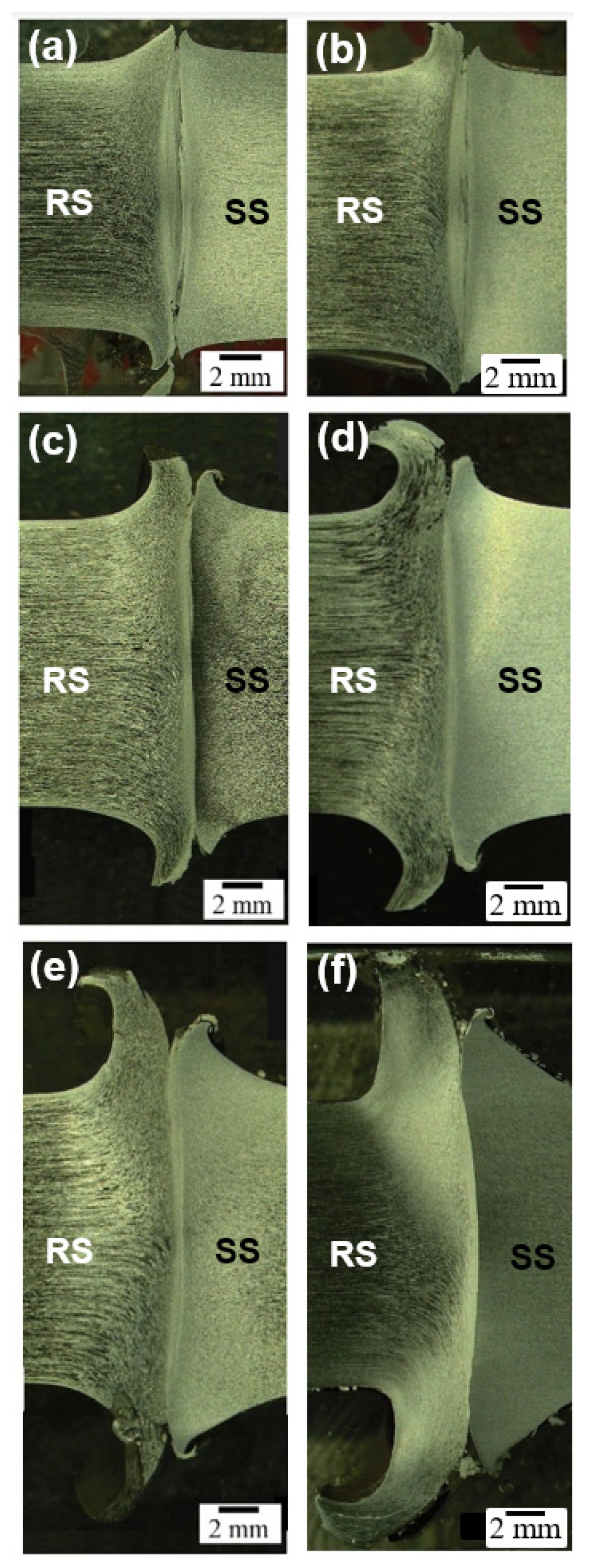
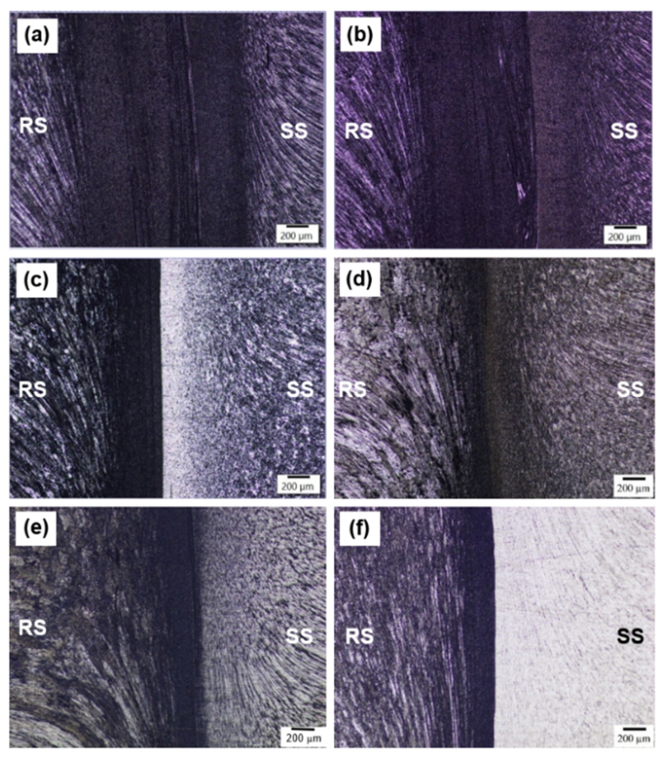
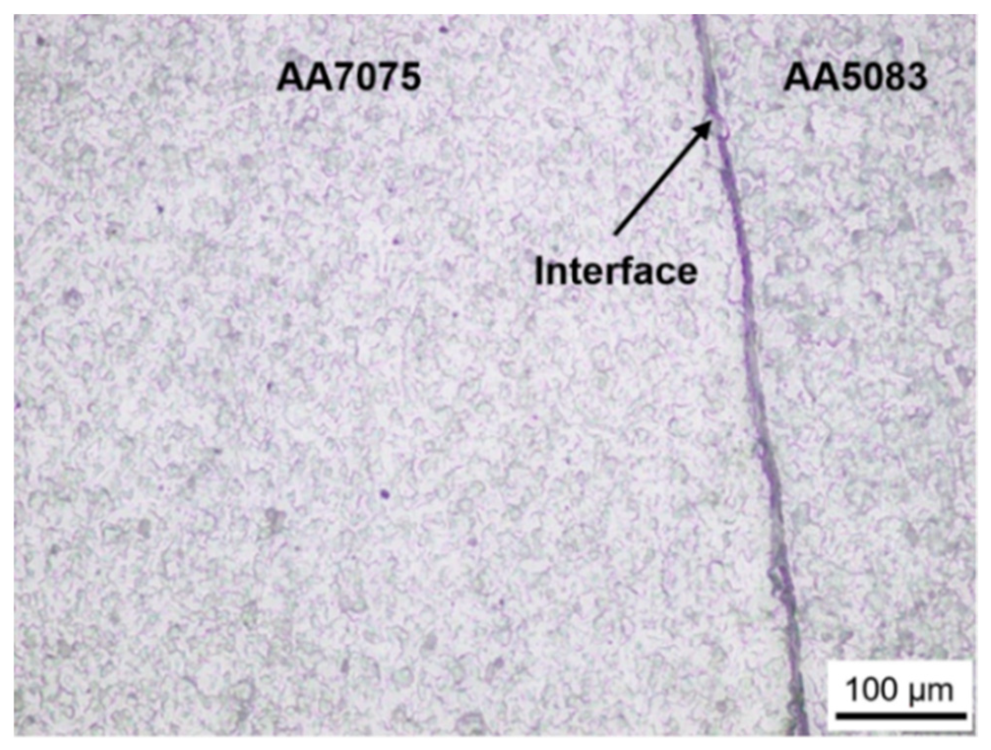
  • Increasing rotational speed causes microstructural changes, i.e., the width of DRZ decreases, the interface becomes thin and coarsening microstructure in TMAZ. The high rotational speed also increases the burn-off length and the amount of flash. These microstructural changes are related to high friction heat under high rotational speed combined with axial force during weld formation.
  • The burn-off length and the amount flash of AA7075 rotary side are higher than that of AA5083 stationary side. These results are associated with the accumulation of friction heat in AA7075 side during welding due its lower thermal conductivity and diffusivity compared with AA5083.
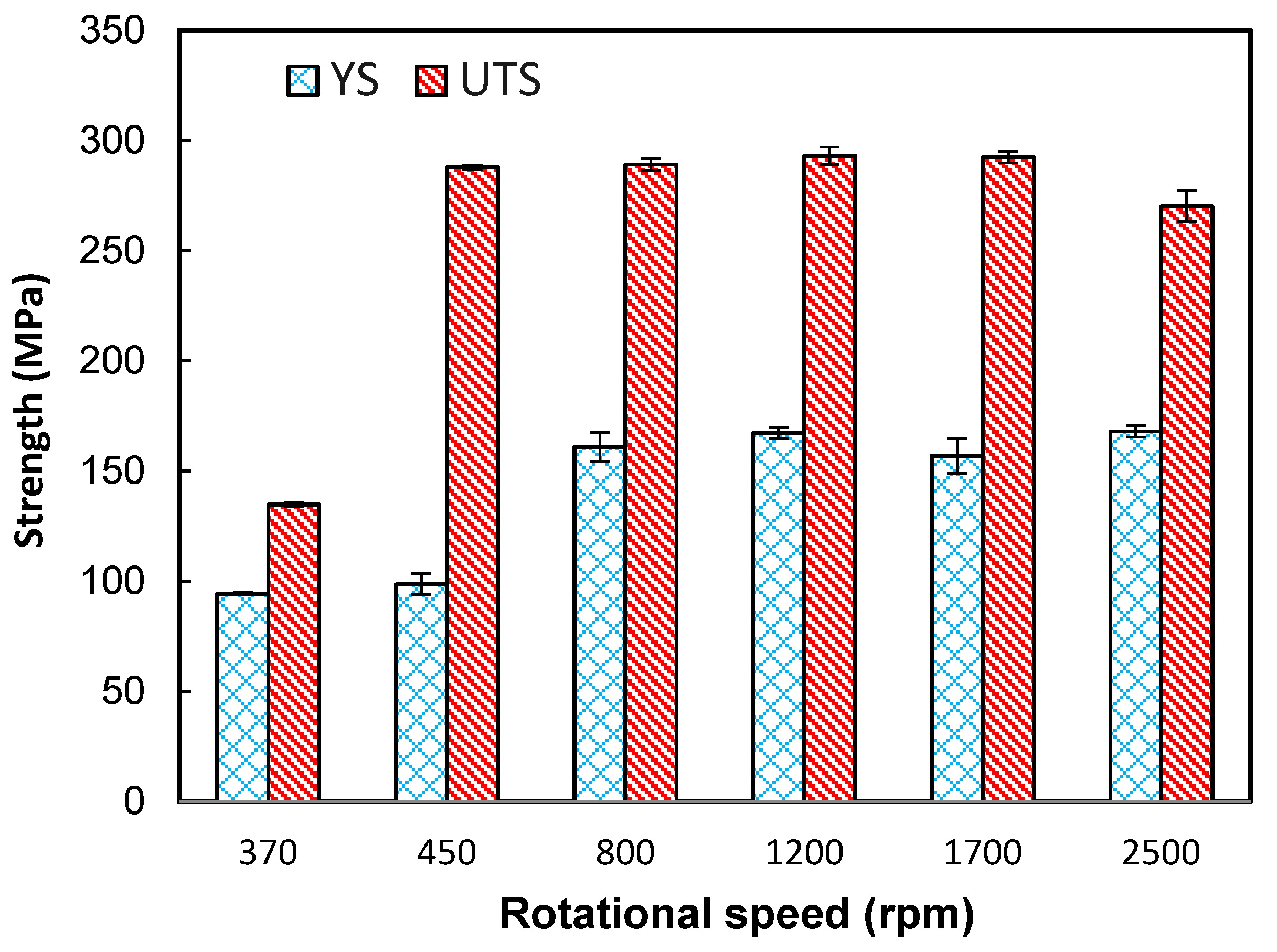
  • A low rotational speed, typically 370 rpm is not sufficient to generate the heat required for bond formation resulting in low strength. In contrast, a high rotational speed, typically 2500 rpm produces high strength weld joints, but it causes high burn-off lengths, which leads to wastage of base metals in the form of flash. It seems that the optimum condition is likely to be achieved at the rotational speed of 1200 rpm owing to the balance between strength and the amount of flash.
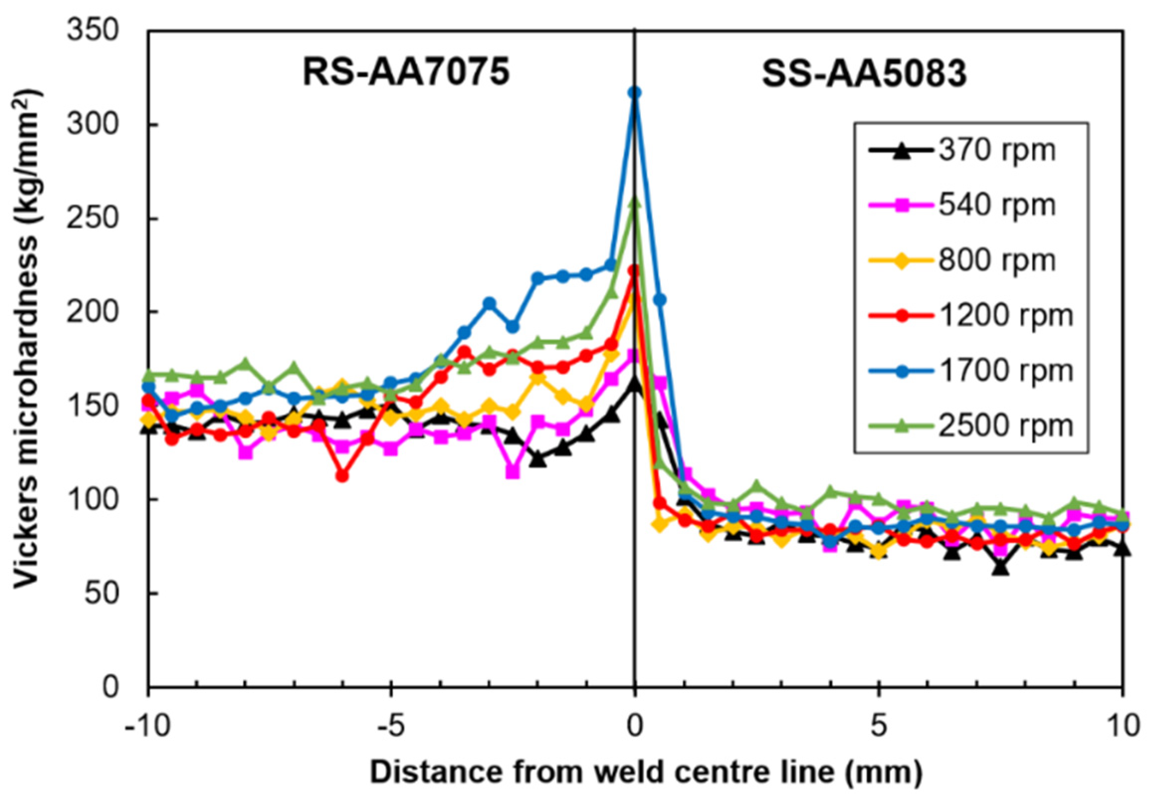
  • The high hardness of TMAZ in AA7075 side is associated with axial force combined with re-precipitation during welding.
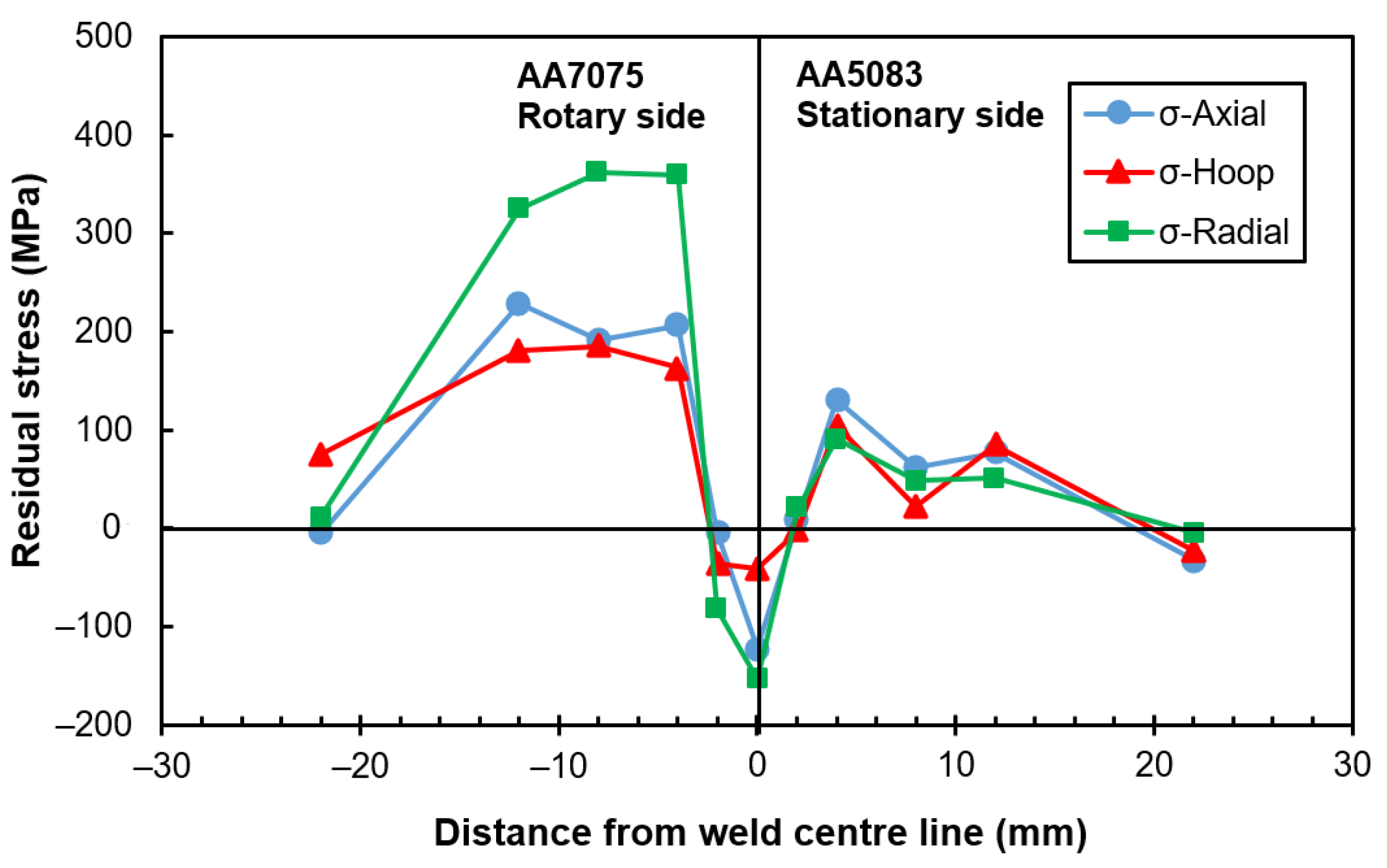
  • The distributions of residual stresses in rotary friction dissimilar AA7075/AA5083 welded joint shows M-shaped profile in which compressive residual stresses are present at the DRZ and its adjacent area whereas outside the DRZ, the residual stresses are tensile to meet static equilibrium.
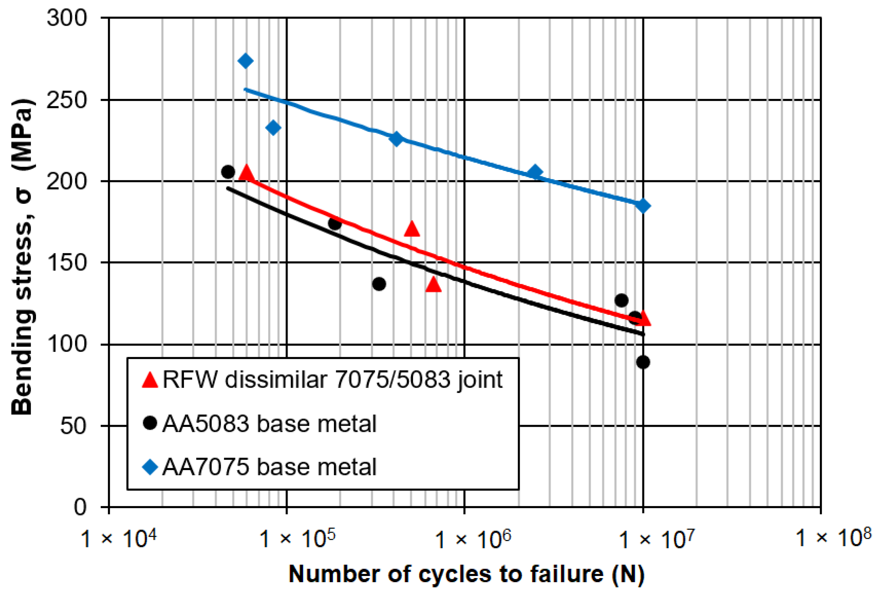
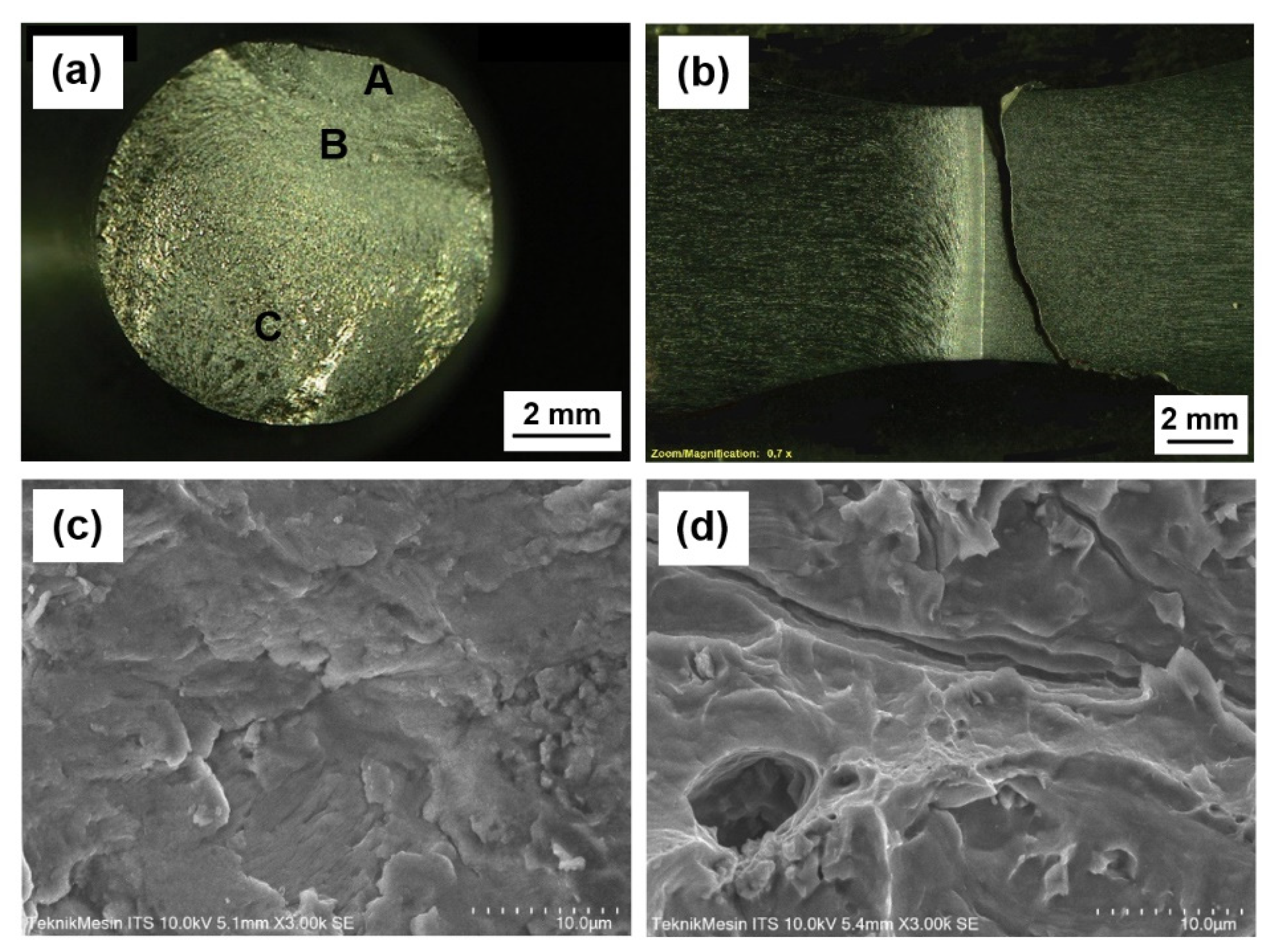
  • The fatigue strength of rotary friction dissimilar AA7075/AA5083 weld joint falls within the fatigue strength of AA5083 and AA7075. The crack initiation is found at the interface which act as stress raiser and the fatigue crack propagates towards TMAZ of AA5083 side which provides easy paths for fatigue crack growth. Under such a condition, the growing crack seems to be controlled by microstructure and tensile residual stress present at the TMAZ in AA5083 side.
  • It seems that apart from rotational speed, other welding parameters such as friction time and forging pressure needs to be paid attention for future work.

Author Contributions

Conceptualization, M.N.I., A.S. and P.T.I.; methodology, M.N.I., A.S. and P.T.I.; formal analysis, M.N.I., A.S. and P.T.I.; investigation, A.S., M.N.I. and R.M.; resources, M.N.I., A.S., R.M. and P.T.I.; data curation, M.N.I., A.S. and R.M.; writing—original draft preparation, A.S. and M.N.I.; writing—review and editing, M.N.I., A.S. and P.T.I.; visualization, M.N.I., A.S. and R.M.; supervision, M.N.I. and P.T.I.; project administration, M.N.I. and P.T.I.; funding acquisition, M.N.I. and A.S. All authors have read and agreed to the published version of the manuscript.

Funding

This research was funded by Badan Pengkajian dan Penerapan Teknologi (BPPT), grant number B-01/DIKLAT/BA/DL02/1/2018.

Institutional Review Board Statement

Not applicable.

Informed Consent Statement

Not applicable.

Data Availability Statement

Not applicable.

Conflicts of Interest

The authors declare no conflict of interest.

References

  1. Davoodi, A.; Esfahani, Z.; Sarvghad, M. Microstructure and Corrosion Characterization of the Interfacial Region in Dissimilar Friction Stir Welded AA5083 to AA7023. Eval. Program Plann. 2016, 107, 133–144. [Google Scholar] [CrossRef]
  2. Ilman, M.N. Heliyon Microstructure and Mechanical Properties of Friction Stir Spot Welded AA5052-H112 Aluminum Alloy. Heliyon 2021, 7, e06009. [Google Scholar] [CrossRef]
  3. Mandal, N.R. Ship Construction and Welding, 1st ed.; Xiros, N.I., Ed.; Springer Nature: New Orleans, LA, USA, 2017; Volume 2. [Google Scholar]
  4. Huang, L.; Hua, X.; Wu, D.; Jiang, Z.; Li, F.; Wang, H.; Shi, S. Microstructural Characterization of 5083 Aluminum Alloy Thick Plates Welded with GMAW and Twin Wire GMAW Processes. Int. J. Adv. Manuf. Technol. 2017, 93, 1809–1817. [Google Scholar] [CrossRef]
  5. Safabali, B.; Shamanian, M.; Eslami, A. Effect of Post-Weld Heat Treatment on Joint Properties of Dissimilar Friction Stir Welded 2024-T4 and 7075-T6 Aluminum Alloys. Trans. Nonferrous Met. Soc. China 2018, 28, 1287–1297. [Google Scholar] [CrossRef]
  6. Ma, M.; Lai, R.; Qin, J.; Wang, B.; Liu, H.; Yi, D. Effect of Weld Reinforcement on Tensile and Fatigue Properties of 5083 Aluminum Metal Inert Gas (MIG) Welded Joint: Experiments and Numerical Simulations. Int. J. Fatigue 2021, 144, 106046. [Google Scholar] [CrossRef]
  7. Fuller, C.B.; Mahoney, M.W.; Calabrese, M.; Micona, L. Evolution of Microstructure and Mechanical Properties in Naturally Aged 7050 and 7075 Al Friction Stir Welds. Mater. Sci. Eng. 2010, 527, 2233–2240. [Google Scholar] [CrossRef]
  8. Kimura, M.; Sakaguchi, H.; Kusaka, M.; Kaizu, K.; Takahashi, T. Characteristics of Friction Welding Between Solid Bar of 6061 Al Alloy and Pipe of Al-Si12CuNi Al Cast Alloy. J. Mater. Eng. Perform. 2015, 24, 4551–4560. [Google Scholar] [CrossRef]
  9. Cai, W.; Daehn, G.; Vivek, A.; Li, J.; Khan, H.; Mishra, R.S.; Komarasamy, M. A State of the Art Review on Solid-State Metal Joining. J. Manuf. Sci. Eng. 2018, 141, 031012. [Google Scholar] [CrossRef]
  10. Maalekian, M.; Kozeschnik, E.; Brantner, H.P.; Cerjak, C. Comparative Analysis of Heat Generation in Friction Welding of Steel Bars. Acta Mater. 2008, 56, 2843–2855. [Google Scholar] [CrossRef]
  11. Bouarroudj, E.; Chikh, S.; Abdi, S.; Miroud, D. Thermal analysis during a rotational friction welding. Appl. Therm. Eng. 2017, 110, 1543–1553. [Google Scholar] [CrossRef]
  12. Łukaszewicz, A. Nonlinear Numerical Model of Friction Heating during Rotary Friction Welding. J. Frict. Wear. 2018, 39, 476–482. [Google Scholar] [CrossRef]
  13. Etesami, S.A.; Enayati, M.H.; Karimzadeh, F.; Rasta, V. Investigating the Properties of Friction Welded 2014 Aluminum Joints Prepared with Different Rotational Speeds. Trans. Indian Inst. Met. 2015, 68, 479–489. [Google Scholar] [CrossRef]
  14. Li, X.; Li, J.; Jin, F.; Xiong, J.; Zhang, F. Effect of Rotation Speed on Friction Behavior of Rotary Friction Welding of AA6061-T6 Aluminum Alloy. Weld. World 2018, 62, 923–930. [Google Scholar] [CrossRef]
  15. Uday, M.B.; Ahmad Fauzi, M.N.; Zuhailawati, H.; Ismail, A.B. Advances in Friction Welding Process: A Review. Sci. Technol. Weld. Join. 2010, 15, 534–558. [Google Scholar] [CrossRef]
  16. Guo, J.F.; Chen, H.C.; Sun, C.N.; Bi, G.; Sun, Z.; Wei, J. Friction Stir Welding of Dissimilar Materials between AA6061 and AA7075 Al Alloys Effects of Process Parameters. Mater. Des. 2014, 56, 185–192. [Google Scholar] [CrossRef]
  17. Özdemir, N. Investigation of the Mechanical Properties of Friction-Welded Joints between AISI 304L and AISI 4340 Steel as a Function Rotational Speed. Mater. Lett. 2005, 59, 2504–2509. [Google Scholar] [CrossRef]
  18. Chander, G.S.; Reddy, G.M.; Rao, A.V. Influence of Rotational Speed on Microstructure and Mechanical Properties of Dissimilar Metal AISI 304-AISI 4140 Continuous Drive Friction Welds. J. Iron Steel Res. Int. 2012, 19, 64–73. [Google Scholar] [CrossRef]
  19. Sahin, M. Joining of Stainless-Steel and Aluminium Materials by Friction Welding. Int. J. Adv. Manuf. Technol. 2009, 41, 487–497. [Google Scholar] [CrossRef]
  20. Sammaiah, P.; Suresh, A.; Tagore, G.R.N. Mechanical Properties of Friction Welded 6063 Aluminum Alloy and Austenitic Stainless Steel. J. Mater. Sci. 2010, 45, 5512–5521. [Google Scholar] [CrossRef]
  21. Hynes, N.R.J.; Velu, P.S. Effect of Rotational Speed on Ti-6Al-4V-AA 6061 Friction Welded Joints. J. Manuf. Process. 2018, 32, 288–297. [Google Scholar] [CrossRef]
  22. Velu, P.S.; Hynes, N.R.J.; Vignesh, N.J. Joining of AA 6061/Ti–6Al–4V with Zinc Interlayer Using Friction Welding Process. J. Braz. Soc. Mech. Sci. Eng. 2019, 41, 537. [Google Scholar] [CrossRef]
  23. Li, X.; Li, J.; Liao, Z.; Jin, F.; Zhang, F.; Xiong, J. Microstructure Evolution and Mechanical Properties of Rotary Friction Welded TC4/SUS321 Joints at Various Rotation Speeds. Mater. Des. 2016, 99, 26–36. [Google Scholar] [CrossRef]
  24. Ochi, H.; Sawai, T.; Yamamoto, Y.; Kurita, M.; Ogawa, K. Evaluation of Tensile Strength and Fatigue Strength of 6061 Aluminum Alloy Friction Welded Joint. Mater. Sci. Res. Int. 2002, 8, 156–161. [Google Scholar] [CrossRef] [Green Version]
  25. Yamamoto, Y.; Ochi, H.; Sawai, T.; Yamaguchi, H.; Ogawa, K. Fatigue Strength of Friction-Welded 6061 Aluminum Alloy Joints. Mater. Trans. 2007, 48, 2909–2913. [Google Scholar] [CrossRef] [Green Version]
  26. Yang, J.; Li, J.; Dong, D.; Liao, J. Effect of Welding Parameters on Microstructure and High Temperature Tensile Properties of FGH96 Superalloy Inertial Friction Welded Joints. J. Aeronaut. Mater. 2019, 39, 33–41. [Google Scholar] [CrossRef]
  27. Hasçalik, A.; Ünal, E.; Özdemir, N. Fatigue Behaviour of AISI 304 Steel to AISI 4340 Steel Welded by Friction Welding. J. Mater. Sci. 2006, 41, 3233–3239. [Google Scholar] [CrossRef]
  28. Lu, D.; You, G.; Luo, J.; Ding, Y.; Zeng, S.; Tong, X. Effects of Rotational Speed on Microstructure and Mechanical Properties of Inertia Friction-Welded 7005–5083 Aluminum Alloy Joints. J. Mater. Sci. 2020, 55, 12338–12352. [Google Scholar] [CrossRef]
  29. ASTM E8; Standard Test Methods for Tension Testing of Metallic Materials; ASTM International: West Conshohocken, PA, USA, 2010. [CrossRef]
  30. Clapham, L.; Krause, T.W.; Olsen, H.; Ma, B.; Atherton, D.L.; Clark, P.; Holden, T.M. Characterization of Texture and Residual Stress in a Section of 610 Mm Pipeline Steel. NDT E Int. 1995, 28, 73–82. [Google Scholar] [CrossRef]
  31. Pan, R.; Pirling, T.; Zheng, J.; Lin, J.; Davies, C.M. Quantification of Thermal Residual Stresses Relaxation in AA7xxx Aluminium Alloy through Cold Rolling. J. Mater. Process. Technol. 2019, 264, 454–468. [Google Scholar] [CrossRef]
  32. Radaj, D. Heat Effects of Welding, 1st ed.; Springer: Berlin, Germany, 1992. [Google Scholar] [CrossRef]
  33. Lancaster, J.F. Metallurgy of Welding, 6th ed.; Woodhead Publishing: Cambridge, UK, 1999. [Google Scholar]
  34. Karkhin, V.A. Thermal Processes in Welding, 2nd ed.; Springer Nature: St. Petersburg, Russia, 2019. [Google Scholar]
  35. Li, P.; Wang, S.; Xia, Y.; Hao, X.; Lei, Z.; Dong, H. Inhomogeneous Microstructure and Mechanical Properties of Rotary Friction Welded AA2024 Joints. J. Mater. Res. Technol. 2020, 9, 5749–5760. [Google Scholar] [CrossRef]
  36. Ashfaq, M.; Rao, K.J. Comparing Bond Formation Mechanism between Similar and Dissimilar Aluminium Alloy Friction Welds. Mater. Sci. Technol. 2014, 30, 329–338. [Google Scholar] [CrossRef]
  37. Zhang, C.; Huang, G.; Cao, Y.; Zhu, Y.; Huang, X.; Zhou, Y.; Li, Q.; Zeng, Q.; Liu, Q. Microstructure Evolution of Thermo-Mechanically Affected Zone in Dissimilar AA2024/7075 Joint Produced by Friction Stir Welding. Vacuum 2020, 179, 109515. [Google Scholar] [CrossRef]
  38. Xie, Y.; Meng, X.; Wang, F.; Jiang, Y.; Ma, X.; Wan, L.; Huang, Y. Insight on Corrosion Behavior of Friction Stir Welded AA2219/AA2195 Joints in Astronautical Engineering. Corros. Sci. 2021, 192, 109800. [Google Scholar] [CrossRef]
  39. James, M.N.; Hughes, D.J.; Chen, Z.; Lombard, H.; Hattingh, D.G.; Asquith, D.; Yates, J.R.; Webster, P.J. Residual Stresses and Fatigue Performance. Eng. Fail. Anal. 2007, 14, 384–395. [Google Scholar] [CrossRef] [Green Version]
  40. Schijve, J. Fatigue of Structure and Materials, 2nd ed.; Springer Science: Delf, The Neitherlands, 2008. [Google Scholar]
  41. Polmear, I.J. Light Alloys, 3rd ed.; Arnold: London, UK, 1995. [Google Scholar]
  42. Ilman, M.N.; Sehono; Muslih, M.R.; Wibowo, H.R.; Wibowo, H. The Application of Transient Thermal Tensioning for Improving Fatigue Crack Growth Resistance of AA5083-H116 FSW Joints by Varying Secondary Heating Temperature. Int. J. Fatigue 2020, 133, 105464. [Google Scholar] [CrossRef]
Figure 1. Microstructures of aluminium alloy rods: (a) AA7075 and (b) AA5083.
Metals 12 00099 g001
Figure 2. Principle setup for rotary friction welding.
Metals 12 00099 g002
Figure 3. Rotary friction welding process stages.
Metals 12 00099 g003
Figure 4. (a) Tensile test specimen according to ASTM E8/E8M and (b) fatigue specimen.
Metals 12 00099 g004
Figure 5. Weld thermal cycles at the distance of (a) 2 mm and (b) 10 mm from the interface.
Metals 12 00099 g005aMetals 12 00099 g005b
Figure 6. The dissimilar AA7075/AA5083 friction welded joints at different rotational speeds with AA7075 and AA5083 are positioned as rotary-side (RS) and stationary-side (SS) respectively. From left to right: 370, 540, 800, 1200, 1700 and 2500 rpm.
Metals 12 00099 g006
Figure 7. Burn-off lengths of the weld joints under various rotational speeds.
Metals 12 00099 g007
Figure 8. Macrostructures of the dissimilar AA7075/AA5083 rotary friction welded joints at various rotational speeds: (a) 370 rpm, (b) 540 rpm, (c) 800 rpm, (d) 1200 rpm, (e) 1700 rpm and (f) 2500 rpm. Note: RS and SS are notations for rotary-side and stationary-side respectively.
Metals 12 00099 g008
Figure 9. Microstructures of the dissimilar AA7075/AA5083 rotary friction welded joints near interfaces at: (a) 370 rpm, (b) 540 rpm, (c) 800 rpm, (d) 1200 rpm, (e) 1700 rpm and (f) 2500 rpm. Note: AA7075 and AA5083 are located as rotary side (RS) and stationary side (SS), respectively.
Metals 12 00099 g009
Figure 10. An example of DRZ microstructure near the interface produced at the rotational speed of 1200 rpm.
Metals 12 00099 g010
Figure 11. Microhardness distributions of the weld joints with AA7075 and AA5083 are located as rotary side (RS) and stationary side (SS) respectively.
Metals 12 00099 g011
Figure 12. The tensile strengths of the weld joints at various rotational speeds.
Metals 12 00099 g012
Figure 13. The residual stress distributions of rotary friction welded dissimilar AA7075/AA5083 joints produced at the rotational speed of 1200 rpm.
Metals 12 00099 g013
Figure 14. S-N curves of the rotary friction welded AA7075/AA5083 joint at 1200 rpm with its base metals.
Metals 12 00099 g014
Figure 15. Fracture surfaces of the weld joint produced at the rotational speed of 1200 rpm after a high cycle fatigue testing taken from: (a) cross section and (b) parallel section of the welded rod with (c,d) SEM fractographs obtained from the regions marked A and B in Figure 15a, respectively.
Metals 12 00099 g015
Table 1. Chemical compositions of AA5083 and AA7075 (wt. %).
MaterialMgZnMnFeCrSiCuTiAl
AA50834.450.030.450.190.070.080.020.01Bal.
AA70752.255.210.120.250.210.321.310.09Bal.
Table 2. Mechanical properties of the base materials.
Mechanical PropertiesAA5083AA7075
Tensile strength (MPa)294.9 ± 05.4 (282 min)592.6 ± 7.4 (556 min)
Yield strength (MPa)176.6 ± 14.9 (171 min)414.8 ± 5.3 (495 min)
Ductility (% elongation)25.7 ± 0.89 (27.5)9.6 ± 0.3 (10)
Vickers microhardness (Hv)86.4 ± 3.77 (96) 185.6 ± 8.4 (175)
Table 3. Friction welding parameters.
ParametersLevels
Rotating speed (rpm)370, 540, 800, 1200, 1700, 2500
Friction pressure (MPa)17
Friction time (s)10
Forging pressure (MPa)85
Forging time (s)4
Publisher’s Note: MDPI stays neutral with regard to jurisdictional claims in published maps and institutional affiliations.

