Article

Orientation Dependence of High Cycle Fatigue Behavior of a <111> Oriented Single-Crystal Nickel-Based Superalloy

1
School of Materials Science and Engineering, Beihang University, No. 37 Xueyuan Road, Beijing 100191, China
2
Research Institute for Frontier Science, Beihang University, Beijing 100191, China
3
Research Institute of Aero-Engine, Beihang University, Beijing 100191, China
*
Author to whom correspondence should be addressed.
Metals 2021, 11(8), 1248; https://doi.org/10.3390/met11081248
Submission received: 30 June 2021 / Revised: 30 July 2021 / Accepted: 2 August 2021 / Published: 6 August 2021
(This article belongs to the Special Issue Advanced Refractory Alloys)

Abstract

:
High cycle fatigue failure has been recognized as one of the major forms of failure of aero-engine blades. This paper presents the high cycle fatigue testing of a Ni-based superalloy near <111> orientation at 800 °C. The fracture morphology and dislocation configuration were analyzed in detail by scanning electron microscopy (SEM) and transmission electron microscopy (TEM) to indicate the influence of orientation deviation degree on the high cycle fatigue properties. The results show that the orientation deviation significantly affects the initiation of the slip systems, which is closely related to fatigue performance. The best fatigue life appears on the precise <111> orientation, and the deformation behavior is controlled by multiple sets of equivalent <110> {111} slip systems. With the increase in orientation deviation, the fatigue properties of the alloy degenerate significantly. On the boundary of <111>-<001>, two groups of <110> {111} slip systems with the maximum Schmid shear stress dominate the deformation behavior. On the other hand, on the <111>-<011> boundary, the formation of stacking faults and rapid cutting of γ’ precipitates results in a negative effect on the fatigue life.

1. Introduction

Nickel-based single-crystal superalloys have been widely used as components in the hot end of advanced aircraft engines and gas turbines due to their excellent high-temperature strength, oxidation resistance and creep properties [1,2]. In the actual service process, turbine blades are often subjected to fatigue damage with cyclic loading, except for creep damage caused by constant centrifugal stress. Among the many factors that cause engine failure, high cycle fatigue (HCF) has proven to be the most common reason [3].
In the past few decades, high cycle fatigue has attracted much attention because of numerous influential factors. Temperature [4,5], frequency [6], load ratio [7], casting conditions [8] and trace elements [9] all have effects on the initiation and propagation of fatigue cracks. However, most of these studies focus on a specific [001] crystal orientation [10,11,12,13]. Vibration stresses resulting in fatigue damage scarcely follow a single axial direction when applied to turbine blades with complex structures. Therefore, crystal orientation, as a significant factor affecting mechanical properties, is noteworthy in the study of high cycle fatigue.
Previous research on the anisotropy of nickel-based single-crystal superalloys mainly focused on creep properties [14,15,16,17]. In Leverant and Kear’s [18] paper, the [111] orientation of Mar M200 exhibits superior creep performance compared to [001] at 760 °C/689 MPa because of the lower Schmid factor of <112> {111} slip system. MacKay and Meier’s early study on MarM247 SX superalloys indicated that orientation deviation significantly affected the creep properties near [001] orientation [19]. Creep lives of crystals near the <001>-<011> boundary of the stereographic triangle are significantly longer than that of the <001>-<111> boundary. Further studies of CMSX-4 by Sass [20] and Matan [21] showed that anisotropy of the primary creep rate is closely related to the number of dominant slip systems and the magnitude of shear stress. In general, the difference in the activation process of the slip systems during plastic deformation caused by different crystal orientation is considered to be the main reason for the creep anisotropy at immediate temperatures. However, the anisotropy of high cycle fatigue properties has only received limited attention.
In this paper, the high cycle fatigue behaviors of a Ni-based single-crystal superalloy with different orientations near <111> orientation were studied. Both coplanar double-slip orientation and non-coplanar double-slip orientation were considered to explain the orientation influencing factors of high cycle fatigue behaviors. Characteristics and mechanisms of fatigue fracture caused by orientation deviation angle and direction are revealed from macroscopic fracture mode and microscopic dislocation movement perspectives.

2. Materials and Methods

A model nickel-based single-crystal superalloy with nominal composition (wt.%) of (7.4–7.8) Al, (3.0–4.5) Ta, (8.9–9.3) Mo, (1.3–2.7) Cr, (1.4–1.6) Re and Ni as the balance, is used as the research object. The master alloy is prepared by vacuum induction melting, and the single-crystal (SX) rods with different deviations from [ 1 ¯ 11 ] were prepared by high-rate solidification (HRS) directional solidification with the seed crystal method. Twenty-millimeter-long seeds with the same desired crystal orientation as the axial direction of test bars were cut directionally from the single-crystal specimens and placed at the bottom of the ceramic mold. Then, the master alloy was melted at 1600 °C and poured on the seeds. Finally, the ceramic mold was withdrawn from the furnace at a withdrawal rate of 3.5 mm/min. The crystal orientations were determined by Laue X-ray diffraction, as shown in Figure 1a. In this paper, test rods with four types of crystal orientations are chosen for this work, which are precise [ 1 ¯ 11 ] orientation, labeled A, 14° deviations from [ 1 ¯ 11 ] orientation along the <111>-<001> boundary, labeled B, and 10° and 15° deviations from [ 1 ¯ 11 ] orientation along the <111>-<011> boundary marked as C and D, respectively. After a full heat treatment with 1300 °C/2 h + 1310 °C/2 h + 1320 °C/2 h + 1330 °C/6 h + 1340 °C/10 h, air cooling (AC) + 1080 °C/2 h and AC + 870 °C/24 h, these rods are processed into test specimens with a gauge diameter of 4 mm and a length of 52 mm, as shown in Figure 1c. Two fatigue samples were machined for each orientation from the same bar.
All tests were performed in 800 °C/σmax = 445 MPa under load control at a stress ratio R = σminmax = −1 and a frequency of 83.3 Hz. The specimens were loaded with sinusoidal wave by the rotating bending method. The fracture surfaces of specimens were observed by EVO-10 scanning electron microscope (SEM, Zeiss, Jena, Germany). Foils for the transmission electron microscope test were cut by a wire cutting machine along the direction perpendicular to the principal stress axis near the fatigue fracture surface, then mechanically ground and electro-chemically thinned at 20 °C in a solution (10 vol% perchloric acid in methanol). Whereafter, the dislocation configurations were analyzed by JEM-2100F transmission electron microscope (TEM, Tokyo, Japan). Observation regions of TEM were selected near the crack source to accurately represent the plastic deformation behavior.

3. Results

3.1. HCF Properties

The results from HCF tests at 800 °C/σmax = 445 MPa for specimens with different crystal orientations are presented in both Table 1 and Figure 2. It is obvious that the HCF properties of this alloy exhibited significant small-angle deviation sensitivity. The precise [ 1 ¯ 11 ] orientation showed the best HCF performance over 107 cycles. With the increased orientation deviation, the HCF properties degraded gradually, while the degree of decline varied according to the deviation direction. Fatigue life of specimens deviated by 15° from [ 1 ¯ 11 ] towards [001] and decreased to an average of 2.42 × 10⁶ cycles, whereas misorientations of 10° and 14° towards [011] directions resulted in a rapid decline in fatigue performance with 1.28 × 10⁶ and 6.76 × 10⁵ cycles, respectively.

3.2. SEM Fractography

SEM observations showed that mixed cleavage and tearing fracture modes exist in the vicinity of <111> orientation. Due to the rotary bending loading mode, the surface of the specimens bears the maximum cyclic stress, which results in the initial cracks mostly at or near the surface. Fractures of specimens with different orientations consist of crack initiation stage, crack propagation stage and final rupture stage, similar to numerous previous studies. However, with the change of deviation direction and angle, the fracture morphology exhibits obvious differences as shown in Figure 3a–d.
The observations from Figure 3a show typical multi-source fracture characteristics in precise <111> orientation. Fatigue cracks generate on the surface and propagate uniformly to the interior along multiple cleavage facets with distinct river pattern and obvious crystallographic characteristics. Many researchers have reported the stage 1 crack growth behavior in nickel-based SX superalloys. These smooth cleavage fracture facets formed during the stage of crack growth and are significantly dependent on the slip planes. Due to face-centered cubic structures, the dominating slip system of nickel-based SX superalloys operated at elevated temperatures is <110> {111} and <112> {111}, hence crack propagation will follow the habit plane {111} [22,23,24]. Fatigue steps are observed at the intersection of different cleavage surfaces as a result of the cross slip of dislocations under cyclic stress.
On the boundary of <111>-<001>, with the orientation deviating from <111>, although multi-source fracture patterns are still observed, crack propagation at stage 1 is not strictly uniform along different <111> planes, but mainly on two types of cleavage planes connected with ridges. Figure 4 shows the schematic diagram of {111} planes on which the different cleavage planes are located. In order to further determine the type of {111} plane, the method of calculating the angle relationship is adopted, as shown in Figure 4c. By measuring the angular relationship between the stress axis and the normal direction of the cleavage plane after cutting the sample longitudinally, one can observe that both fracture surfaces are 63° off the stress axis, which is close to the (111) and ( 11 1 ¯ ) planes (64°). Cracks propagate inward along these cleavage planes, resulting in a gradual decrease in the bearing capacity area and eventual failure under tensile overload. The occurrence of river patterns provides evidence for cyclic plastic deformation, and the variation of distance between slip trace indicates that plastic deformation accelerates with crack growth.
A distinct fracture mode occurs when the orientation deviates towards [011] along the <111>-<011> boundary. Both Figure 3c,d show a unitary crack source regardless of whether misorientation is 10° or 14°. Crack propagation at a single cleavage plane with river patterns and stepwise features can be observed simultaneously. Angular relation calculations indicate that the fracture surface is (111) plane. It was also verified by Laue X-ray diffraction after polishing the cleavage plane of the sample, and the result was added in Appendix B. The fatigue fracture consists of a dominant stage 1 and a transient stage 2. Further comparison of Figure 3a–d indicates that with the increase in orientation deviation, the fracture pattern with a single cleavage plane becomes more evident. Moreover, this transformation of deformation behavior results in rapid degradation of fatigue performance.

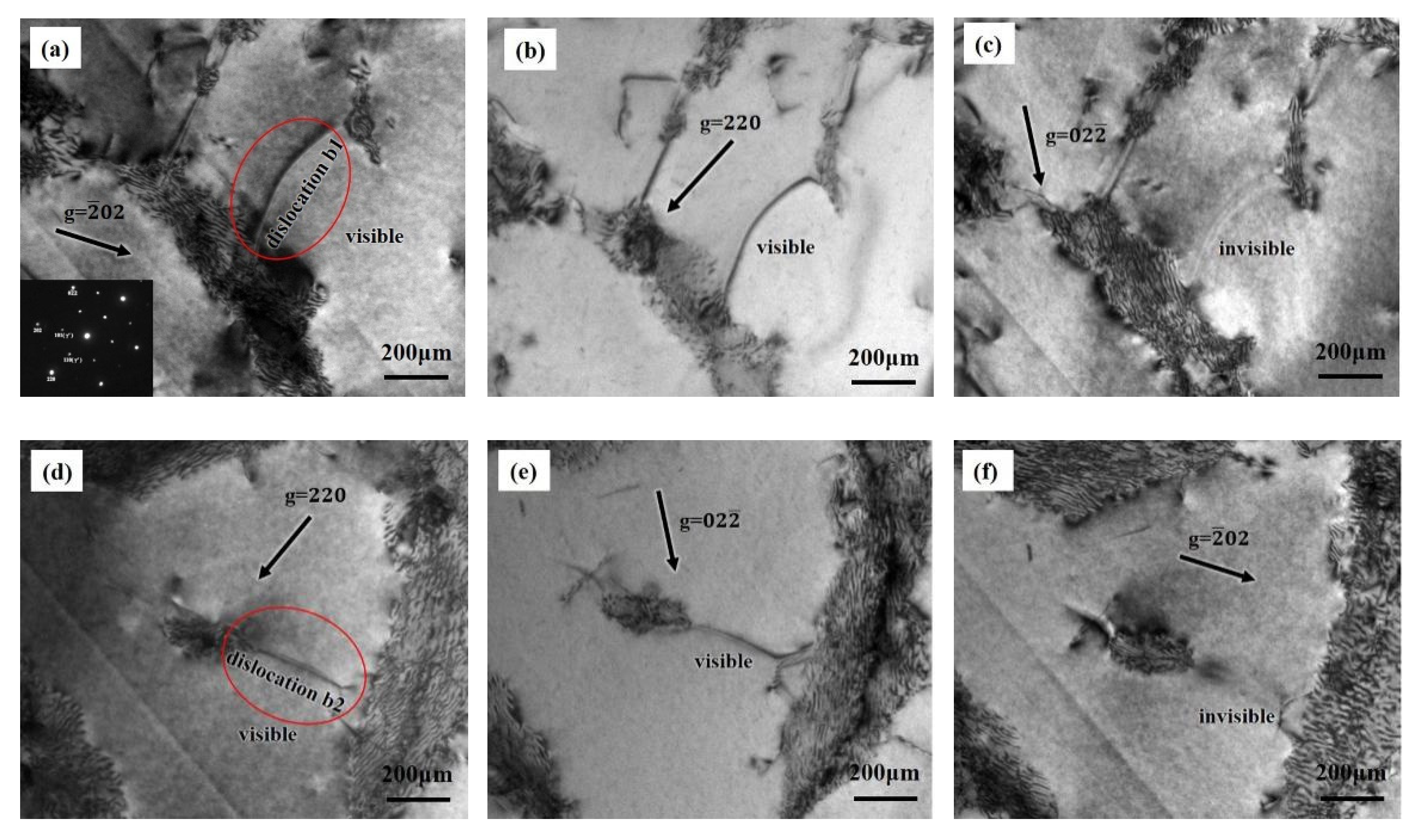
3.3. Dislocation Configurations

TEM micrographs in Figure 5a show typical deformation substructures from the samples with orientation A after HCF failure. Under this test condition, the γ/γ’ microstructures after fracture were roughly the same as that of the heat treated. The distribution of dislocations in the two phases is not uniform, but mainly concentrated in the γ matrix. Several groups of dislocations with different Burgers vectors in the matrix deposit on the γ/γ ‘interface, forming dislocation networks. A few dislocations cut into the γ ‘precipitate in the form of a/2 <110>, and no stacking faults cutting was observed. The basic characteristic of a nickel-based superalloy structure is that the cubic γ’ phase is embedded in the γ matrix, resulting in the formation of three pairs of equivalent γ channels around the γ’ cubic precipitate. When the applied stress is in the precise <111> orientation, three types of γ channels have the same stress state and similar dislocation distribution.
In the B oriented specimen, the dislocation configuration is similar to that of the sample with A orientation as shown in Figure 5b. Two types of a/2<110> dislocations were observed in the γ matrix and at the γ/γ’ interface, while there were also very few present in the γ’ precipitates. The nature of the dislocations cutting into the γ’ precipitate was analyzed in detail under two-beam condition as shown in Figure 6. Typical dislocations b1 and b2 as indicated by the arrows are presented in Figure 6a–f. Several sets of g diffraction conditions have been used to form images. Both of these dislocations are visible under g = 220. The difference is that the b1 dislocation is visible under g = 2 ¯ 02 operation reflection but out of contrast in the g = 02 2 ¯ condition. Since g · b=0, the Burgers vector of b1 is inferred to be a/2[011]. Similarly, the comparative analysis of dislocation b2 indicates that it is visible under g = 02 2 ¯ , while invisible under g = 2 ¯ 02 diffraction condition. The Burgers vector of b2 is a/2[101]. According to the characterization of different operation reflections, the actuation of the slip system is obviously changed with the crystal orientation deviating from <111> direction.
Compared with orientation A and B, the differences of samples on the <111>-<011> boundary are striking. Orientation deviation causes a variation of the stress state in the three different types of matrix channels, result in significant differences in the number of dislocations in different channels as shown in Figure 7. Meanwhile, in addition to high-density dislocations in γ channels, there are many unidirectional stacking faults associated with <112> cutting both the γ matrix and γ’ precipitates as presented in Figure 6b, which indicates that <112> {111} slip systems participate in the deformation instead of being dominated only by <110> {111} slip systems.

4. Discussion

Although HCF differs from creep in the manner of stress loading, both of them exhibit plastic behavior below yield strength. In this paper, the analysis of plastic behavior is mainly focused on the crack initiation on the sample surface to avoid the complex stress state in the late deformation. The initiation and propagation of fatigue cracks are the result of periodic slip of the slip system, that is, cyclic plastic deformation caused by dislocation movement. At elevated temperatures, the anisotropic behavior of nickel-based SX superalloys is closely related to the critical shearing stress of <110> {111} and <112> {111} slip systems [25]. Schmid factors of different specimens are shown in the Table 2. The value of the Schmid factor represents the ease with which the slip system is operated. It should be noted that the Schmid factors for all slip systems are not listed here. Only <110> {111} slip systems with the largest values and the <112> {111} slip systems that can be generated by the reaction are represented. Complete data for all slip systems are added in Appendix A. For the precise <111> orientation, TEM photographs in Figure 4a show that dislocation movement was mainly concentrated in the γ channel with few γ’ precipitates cutting. It was indicated that plastic deformation was mainly controlled by the <110> {111} octahedral sliding system, since the shear stress of the <112> {111} sliding system on <111> orientation was relatively low. Six equivalent slip systems operated uniformly on three <111> planes, which was consistent with the macroscopic fracture. During the deformation process operated by multiple <110> {111} slip systems, dense dislocation networks were formed at the γ/γ ‘interface through a continuous cross-slip and reaction of a/2[110] dislocations with different Burgers vectors. Previous studies [26] on creep behavior have shown that dense interfacial dislocation networks prevent dislocations in the γ matrix from cutting γ’ precipitates, resulting in an obvious work hardening, which is an important reason for the transition from the first creep stage to the second. In the [111] oriented sample, since the Schmid factors of initial slip and cross slip planes are almost equivalent, the cross slip of screw dislocations in matrix channels occurs easily under the cyclic stress [27], which promotes the generation of γ/γ’ interface dislocation networks. Furthermore, <110> {111} slip systems have the lowest shear stress in <111> direction. Both the low resolved shear stress and interfacial dislocation networks can contribute to resistance to the movement of dislocations, resulting in the best high cycle fatigue performance of <111> specimens.
As can be seen from Table 2, misorientation from <111> results in an obvious difference in the actuation of slip systems. Furthermore, (111) [ 1 ¯ 01 ] and ( 11 1 ¯ ) [011] slip systems dominate when the orientation deviates towards <001> along the <111>-<001> boundary. No stacking faults were observed according to the results of TEM, which reveals that the dominant slip system was also <110> {111} despite a slight increase in Schmid factor of <112> {111} in this direction. Previous research on creep anisotropy of nickel-based SX superalloys at elevated temperatures has suggested that stacking fault shear is frequently associated to a reaction of a/2 <110> {111} dislocations in the γ matrix [28]. A typical reaction might be written as:
a/2[011] + a/2[101] = a/3[112] + a/6[112]
For sufficiently applied stress, the a/3<112> dislocation may cut into γ’ accompanied by rapid plastic deformation, while a/6<112> dislocations remain at the γ/γ’ interface. Note that the reactions require appropriate dislocations rather than two arbitrary dislocations [29,30]. Considering the orientations along the <111>-<001> boundary, the most highly stressed dislocations a/2[ 1 ¯ 01 ] (111) and a/2[011] ( 11 1 ¯ ) with the Schmid factor of 0.38 can combine to form a/3[ 1 ¯ 12 ] ( 1 1 ¯ 1 ) and a/6[ 1 ¯ 12 ] ( 1 1 ¯ 1 ). However, a finite Schmid factor of 0.088 is inadequate to obtain a/3[ 1 ¯ 12 ] ( 1 1 ¯ 1 ) dislocations shear into γ’ precipitates. In addition, <110> dislocations on different {111} planes are not easily combined to generate <112> dislocations. Macroscopic fractures are characterized as stage 1 fatigue along two major <111> planes, which provide evidence for the operation of (111) [ 1 ¯ 01 ] and ( 11 1 ¯ ) [011] from another side. Meanwhile, compared with the precise <111> orientation, the dominant <110> {111} slip systems subjected to greater shear stress result in a decline in fatigue performance.
Instead of uniform deformation on multiple slip planes, a coplanar double slip occurs when the orientation deviates from precise <111> by 10° towards <011> along the <111>-<011> boundary. In other words, two dominant <110> {111} slip systems with maximum shear stress are located on the same plane. TEM observations in Figure 6 indicated that unidirectional stacking faults shear γ’ is the dominative mechanism of plastic deformation. According to the analysis above, coplanar (111) [ 1 ¯ 01 ] and (111) [   1 ¯ 10 ] slip systems can participate in the generation of (111) [ 2 ¯ 11 ] dislocation distribution in the same (111) plane. Furthermore, the generated [ 2 ¯ 11 ] dislocation was dominant in the dodecahedral slip system, which can continue to form stacking fault bands cutting into γ’ precipitates. The resulting rapid plastic deformation promotes crack initiation and propagation and leads to a rapid decline in fatigue life.

5. Conclusions

The present study is focused on the effect of orientation deviation near <111> orientation on high cycle fatigue properties of a nickel-based single-crystal superalloy. High cycle fatigue tests were carried out at 800 °C (σmax = 445 MPa), and the fatigue deformation mechanism was studied from both macroscopic and microscopic levels, respectively. The conclusions are summarized as follows:
(1)
The precise <111> orientation showed the best fatigue performance. With the increase in orientation deviation, the fatigue properties degenerate significantly.
(2)
Fractographic investigation revealed that, under testing conditions, the precise <111> orientation shows a multi-source fracture mode, and its deformation is mainly controlled by multiple sets of equivalent <110> {111} slip systems in three γ channels with the same stress state.
(3)
On the boundary of [111]-[001], although the alloy still maintains the multi-source fracture mode, the dominant slip systems are changed into two <110> {111} slip systems with maximum Schmid shear stress.
(4)
As the orientation deviates towards [011] along the [111]-[011] boundary, the fracture mode of the alloy changes from multi-source to single-source. Stacking faults formed by two <110> {111} dislocations cutting into γ’ precipitates result in rapid plastic deformation and has a negative effect on the fatigue life.

Author Contributions

S.L. and S.G. conceived the project and designed experiments. B.H. and Y.P. carried out most of the experiments. B.H. and S.L. wrote the paper. All authors contributed to the interpretation and presentation of the results. All authors have read and agreed to the published version of the manuscript.

Funding

This research is sponsored by (1) National Key Research and Development Program of China under grant No. 2017YFA0700700; (2) National Science and Technology Major Project (2017-I-0001-0013).

Institutional Review Board Statement

Not applicable.

Informed Consent Statement

Not applicable.

Data Availability Statement

All data needed to evaluate the conclusions in the paper are present in the paper and/or the Supplementary Materials. Additional data related to this paper may be requested from the authors.

Conflicts of Interest

There are no conflict to declare.

Appendix A

Table A1. Schmid factors for <110> {111} slip systems of specimens A–D.
Slip SystemABCD
(111) [ 1 1 ¯ 0 ]0.1570.2850.3730.405
(111) [ 1 ¯ 01 ]0.1570.3800.3730.405
(111) [ 01 1 ¯ ]0.3140.0950.0000.000
( 1 ¯ 11 ) [110]0.0000.0000.1520.218
( 1 ¯ 11 ) [101]0.0000.2090.1520.218
( 1 ¯ 11 ) [ 01 1 ¯ ]0.0000.2090.0000.000
( 1 1 ¯ 1 ) [011]0.3140.0760.2210.187
( 1 1 ¯ 1 ) [110]0.1570.0000.0380.045
( 1 1 ¯ 1 ) [ 1 ¯ 01 ]0.1570.0760.1840.142
( 11 1 ¯ ) [ 1 ¯ 10 ]0.1570.2850.1840.142
( 11 1 ¯ ) [101]0.3140.0950.0380.045
( 11 1 ¯ ) [011]0.1570.3800.2210.187
Table A2. Schmid factors for <112> {111} slip systems of specimens A–D.
Slip SystemABCD
(111) [ 11 ¯ 2 ]0.0000.2740.2150.234
(111) [ 1 ¯ 2 1 ¯ ]0.0000.1100.2150.234
(111) [ 2 11 ¯ ]0.0000.3840.4310.467
( 1 ¯ 11 ) [ 1 1 ¯ 2 ]0.1570.2410.0880.126
( 1 ¯ 11 ) [ 12 1 ¯ ]0.1570.1210.0880.126
( 1 ¯ 11 ) [ 211 ]0.3140.1210.1750.251
( 1 1 ¯ 1 ) [ 1 ¯ 12 ]0.1570.0880.2340.190
( 1 1 ¯ 1 ) [121]0.3140.0440.1490.134
( 1 1 ¯ 1 ) [ 21 1 ¯ ]0.1570.0440.0840.056
( 11 1 ¯ ) [112]0.3140.2740.1490.134
( 11 1 ¯ ) [ 1 ¯ 21 ]0.1570.3840.2340.190
( 11 1 ¯ ) [ 2 1 ¯ 1 ]0.1570.1100.0840.056

Appendix B

Figure A1. Laue diffraction spot pattern of a C-oriented sample in a single slip system. (a) The polished surface of the sample. (b) Laue’s diffraction spot pattern.
Metals 11 01248 g0a1

References

  1. Pollock, T.M.; Tin, S. Nickel-Based Superalloys for Advanced Turbine Engines: Chemistry, Microstructure and Properties. J. Propuls. Power 2006, 22, 361–374. [Google Scholar] [CrossRef]
  2. Reed, R. The Superalloys; Cambridge University Press: Cambridge, UK, 2006. [Google Scholar]
  3. Cowles, B.A. High cycle fatigue in aircraft gas turbines—An industry perspective. Int. J. Fract. 1996, 80, 147–163. [Google Scholar] [CrossRef]
  4. Yu, J.; Yang, Y.; Sun, X.; Guan, H.; Hu, Z. Rotary bending high-cycle fatigue behavior of DD32 single crystal superalloy containing rhenium. J. Mater. Sci. 2012, 47, 4805–4812. [Google Scholar] [CrossRef]
  5. Liu, Y.; Yu, J.J.; Xu, Y.; Sun, X.F.; Guan, H.R.; Hu, Z.Q. High cycle fatigue behavior of a single crystal superalloy at elevated temperatures. Mater. Ence Eng. A 2007, 454, 357–366. [Google Scholar] [CrossRef]
  6. Maclachlan, D.W.; Knowles, D.M. Fatigue behaviour and lifing of two single crystal superalloys. Fatigue Fract. Eng. Mater. Struct. 2010, 24, 503–521. [Google Scholar] [CrossRef]
  7. Muller, S.; Rosler, J.; Sommer, C.; Hartnagel, W. The Influence of Load Ratio, Temperature, Orientation and Hold Time on Fatigue Crack Growth of CMSX-4, Superalloys. In Proceedings of the Ninth International Symposium on Superalloys 2000, Seven Springs, PA, USA, 17–21 September 2000. [Google Scholar]
  8. Lamm, M.; Singer, R.F. The Effect of Casting Conditions on the High-Cycle Fatigue Properties of the Single-Crystal Nickel-Base Superalloy PWA 1483. Metall. Mater. Trans. A 2007, 38, 1177–1183. [Google Scholar] [CrossRef]
  9. Al-Jarba, K.A.; Fuchs, G.E. Elevated temperature, high cycle fatigue behavior of carbon-containing single crystal Ni-Based superalloys. Mater. Sci. Eng. 2019, 760, 287–295. [Google Scholar] [CrossRef]
  10. Lukáš, P.; Kunz, L.; Svoboda, M. High cycle fatigue of superalloy single crystals at high mean stress. Mater. Ence Eng. A 2004, 387, 505–510. [Google Scholar] [CrossRef]
  11. Ormastroni, L.M.B.; Suave, L.M.; Cervellon, A.; Villechaise, P.; Cormier, J. LCF, HCF and VHCF life sensitivity to solution heat treatment of a third-generation Ni-based single crystal superalloy. Int. J. Fatigue 2019, 130, 105247. [Google Scholar] [CrossRef]
  12. Wright, P.K.; Jain, M.; Cameron, D. High cycle fatigue in a single crystal superalloy: Time dependence at elevated temperature. Superalloys 2004, 2004, 657–666. [Google Scholar]
  13. Liwu, J.; Shusuo, L.; Yafang, H. Rotating bending fatigue property of the Ni3Al-based single crystal superalloy IC6SX at 900 °C. IOP Conf. Ser. Mater. Sci. Eng. 2017, 182, 012058. [Google Scholar]
  14. Han, G.; Yu, J.; Sun, X.; Hu, Z. Effect of Threshold Stress on Anisotropic Creep Properties of Single Crystal Nickel-Base Superalloy SRR99. J. Mater. Sci. Technol. 2012, 28, 439–445. [Google Scholar] [CrossRef]
  15. Nörtershäuser, P.; Frenzel, J.; Ludwig, A.; Neuking, K.; Eggeler, G. The effect of cast microstructure and crystallography on rafting, dislocation plasticity and creep anisotropy of single crystal Ni-base superalloys. Mater. Sci. Eng. A 2015, 626, 305–312. [Google Scholar] [CrossRef]
  16. Agudo Jácome, L.; Nörtershäuser, P.; Heyer, J.K.; Lahni, A.; Frenzel, J.; Dlouhy, A.; Somsen, C.; Eggeler, G. High-temperature and low-stress creep anisotropy of single-crystal superalloys. Acta Mater. 2013, 61, 2926–2943. [Google Scholar] [CrossRef]
  17. Caron, P.; Khan, T.; Ohta, Y.; Nakagawa, Y.G. Creep deformation anisotropy in single crystal superalloys. Superalloys 1988, 1988, 215–224. [Google Scholar]
  18. Leverant, G.R.; Kear, B.H. The mechanism of creep in gamma prime precipitation-hardened nickel-base alloys at intermediate temperatures. Metall. Mater. Trans. B 1970, 1, 491–498. [Google Scholar] [CrossRef]
  19. MacKay, R.A.; Maier, R.D. The influence of orientation on the stress rupture properties of nickel-base superalloy single crystals. Metall. Trans. A 1982, 13, 1747–1754. [Google Scholar] [CrossRef]
  20. Sass, V.; Glatzel, U.; Feller-Kniepmeier, M. Anisotropic creep properties of the nickel-base superalloy CMSX-4. ACTA Metall. 1996, 44, 1967–1977. [Google Scholar] [CrossRef]
  21. Matan, N.; Cox, D.C.; Carter, P. Creep of CMSX-4 superalloy single crystals: Effects of misorientation and temperature. Acta Mater. 1999, 47, 1549–1563. [Google Scholar] [CrossRef]
  22. Miao, J.; Pollock, T.M.; Jones, J.W. Microstructural extremes and the transition from fatigue crack initiation to small crack growth in a polycrystalline nickel-base superalloy. Acta Mater. 2012, 60, 2840–2854. [Google Scholar] [CrossRef]
  23. Leverant, G.R.; Gell, M. The influence of temperature and cyclic frequency on the fatigue fracture of cube oriented nickel-base superalloy single crystals. Metall. Trans. A 1975, 6, 367. [Google Scholar] [CrossRef]
  24. Liu, L.; Husseini, N.S.; Torbet, C.J.; Lee, W.K.; Pollock, T.M. In situ synchrotron X-ray imaging of high-cycle fatigue crack propagation in single-crystal nickel-base alloys. Acta Mater. 2011, 59, 5103–5115. [Google Scholar] [CrossRef]
  25. Kakehi, K. Effect of plastic anisotropy on the creep strength of single crystals of a nickel-based superalloy. Metall. Mater. Trans. A 2000, 31, 421–430. [Google Scholar] [CrossRef]
  26. Han, G.M.; Yu, J.J.; Sun, Y.L.; Sun, X.F.; Hu, Z.Q. Anisotropic stress rupture properties of the nickel-base single crystal superalloy SRR99. Mater. Sci. Eng. A 2010, 527, 5383–5390. [Google Scholar] [CrossRef]
  27. Wang, G.; Liu, J.; Liu, J.; Jin, T.; Sun, X.; Sun, X.; Hu, Z. High Temperature Stress Rupture Anisotropy of a Ni-Based Single Crystal Superalloy. J. Mater. Sci. Technol. 2016, 32, 1003–1007. [Google Scholar] [CrossRef]
  28. Pollock, T.M.; Field, R.D. Chapter 63 Dislocations and high-temperature plastic deformation of superalloy single crystals. Dislocations Solids 2002, 11, 566–568. [Google Scholar]
  29. Rae, C.M.F.; Rist, M.A.; Cox, D.C.; Reed, R.C.; Matan, N. On the primary creep of CMSX-4 superalloy single crystals. Metall. Mater. Trans. A 2000, 31, 2219–2228. [Google Scholar] [CrossRef]
  30. Rae, C.M.F.; Reed, R.C. Primary creep in single crystal superalloys: Origins, mechanisms and effects. Acta Mater. 2007, 55, 1067–1081. [Google Scholar] [CrossRef]
Figure 1. (a) Orientations of specimens A–D in the standard stereographic triangle. (b) Secondary electron SEM micrograph of initial γ/γ′ microstructure with the crystallographic orientation <111> after the standard heat treatment. (c) Schematic of specimen for high cycle fatigue test (unit: mm).
Metals 11 01248 g001
Figure 2. Effect of orientation deviation from <111> on the 850 °C/σmax = 445 MPa high cycle fatigue life.
Metals 11 01248 g002
Figure 3. SEM images of fracture surface of specimens with different orientations tested at 800 °C. (a) Precise <111> orientation A. (b) Orientation B on the <111>-<001> boundary. (c,d) Orientation C and D on the <111>-<011> boundary.
Metals 11 01248 g003
Figure 4. Diagram of slip planes at fracture surface. (a) Orientation B. (b) Orientation D. (c) Angle calculation diagram of B-oriented sample.
Metals 11 01248 g004
Figure 5. TEM images near fatigue source showing the dislocation configuration in the γ matrix and γ’ precipitates of specimens ruptured at 800 °C/σmax = 445 MPa. (a) Dislocation networks with no stacking fault in orientation A. (b) Irregular dislocation networks and a small amount of a/2<011> dislocations cutting into γ’ precipitates in orientation B.
Metals 11 01248 g005
Figure 6. Two-beam TEM bright field images of typical dislocations labeled b1 and b2 in γ’ precipitates of orientation B after rupture. (a) Dislocation b1 with g =   2 ¯ 02 diffraction condition. (b) g = 220. (c) g =   02 2 ¯ . (d) Dislocation b2 with g = 220 diffraction condition. (e) g = 02 2 ¯ . (f) g = 2 ¯ 02 .
Metals 11 01248 g006
Figure 7. TEM micrographs of orientation C after rupture. (a) Dislocation density differences in different types of matrix channels. (b) Dense stacking faults along the same direction.
Metals 11 01248 g007
Table 1. 850 °C/σmax = 445 MPa high cycle fatigue (HCF) properties for different orientations to the model alloy.
OrientationSample 1Sample 2Average
A9.99 × 106 > 1 × 1071 × 107
B2.48 × 1062.36 × 1062.42 × 106
C1.08 × 1061.48 × 1061.28 × 106
D6.55 × 1056.96 × 1056.76 × 105
Table 2. Calculated Schmid factors for specimens A–D on part of the most potentially activated slip systems.
OrientationSlip SystemsSchmid Factors
A( 1 ¯ 11 ) [ 110 ]0.272
( 1 ¯ 11 ) [ 101 ]0.272
( 11 1 ¯ ) [ 112 ]0.314
B(111) [ 1 ¯ 01 ]0.380
( 11 1 ¯ ) [011]0.380
(1 1 ¯ 1 ) [ 1 ¯ 12 ]0.088
C(111) [1 1 ¯ 0 ]0.373
(111) [ 1 ¯ 01 ]0.373
(111) [ 2 ¯ 11 ]0.431
D(111) [1 1 ¯ 0 ]0.405
(111) [ 1 ¯ 01 ]0.405
(111) [ 2 ¯ 11 ]0.467
Publisher’s Note: MDPI stays neutral with regard to jurisdictional claims in published maps and institutional affiliations.

