Article

Real-Time Weld Gap Monitoring and Quality Control Algorithm during Weaving Flux-Cored Arc Welding Using Deep Learning

School of Mechanical Convergence Engineering, Hanyang University, Seoul 04763, Korea
*
Author to whom correspondence should be addressed.
Metals 2021, 11(7), 1135; https://doi.org/10.3390/met11071135
Submission received: 9 June 2021 / Revised: 15 July 2021 / Accepted: 16 July 2021 / Published: 18 July 2021
(This article belongs to the Special Issue Quality Assessment and Process Management of Welded Joints)

Abstract

:
In the flux-cored arc welding process, which is most widely used in shipbuilding, a constant external weld bead shape is an important factor in determining proper weld quality; however, the size of the weld gap is generally not constant, owing to errors generated during the shell forming process; moreover, a constant external bead shape for the welding joint is difficult to obtain when the weld gap changes. Therefore, this paper presents a method for monitoring the weld gap and controlling the weld deposition rate based on a deep neural network (DNN) for the automation of the hull block welding process. Welding experiments were performed with a welding robot synchronized with the welding machine, and the welding quality was classified according to the experimental results. Welding current and voltage signals, as the robot passed through the weld seam, were measured using a trigger device and analyzed in the time domain and frequency domain, respectively. From the analyzed data, 24 feature variables were extracted and used as input for the proposed DNN model. Consequently, the offline and online performance verification results for new experimental data using the proposed DNN model were 93% and 85%, respectively.

1. Introduction

Welding is widely applied in heavy industries, such as the automobile and aerospace industries [1,2,3,4]. It plays a critical role in shipbuilding, accounting for approximately 50% of the entire shipbuilding process [5]. In the manufacture of automobile bodies using spot welding, automated manufacturing lines using robots have advanced while maintaining a low defect rate [6]. However, when unexpected disturbances such as welding deformation and weld shape changes occur in large and complex hull block fillet welding processes, welding defects, such as the attainment of values greater or less than the required theoretical throat thickness standard, may occur, thereby failing to ensure consistent welding quality [7]. In addition, it is necessary to exercise caution with the control microdefects as that can lead to the formation of fatigue cracks [8]. Therefore, the majority of operations in the hull welding process are still dependent on the experience of skilled welders, and the development of an automated welding process remains an important task [9].
Recently, research on welding condition monitoring using artificial intelligence and camera vision devices has gained increasing attention because of the increasing demand for manufacturing intelligence, cost reduction, efficiency, and quality. This research can be classified into three areas of application: weld defect prediction [10,11,12], weld bead shape prediction [13,14], and weld seam tracking [15,16,17]. For instance, Zhang et al. [10] developed a convolutional neural network (CNN) algorithm based on a multi-sensor system, including an auxiliary illumination (AI) visual sensor system, UVV band visual sensor system, spectrometer, and two photodiodes to detect three different welding defects during high-power disk laser welding. Yu et al. [11] proposed a deep neural network (DNN)-based quality assessment method based on a spectrometer in the laser beam welding (LBW) process. Shin et al. [12] proposed a DNN-based nondestructive testing method for the detection and prediction of porosity defects in real time based on welding voltage signals. Nagesh and Datta [13] used back-propagation neural networks to associate welding process variables with the features of bead geometry and penetration. Pinto-Lopera et al. [14] presented a novel technique for real-time measurement of the width and height of weld beads during gas metal arc welding (GMAW) using a single high-speed camera and a long-pass optical filter in a passive vision system. Xu et al. [15] presented a technology for real-time seam tracking to overcome the limitations of teaching-playback welding robots in seam tracking control during gas tungsten arc welding (GTAW). Zou et al. [16] studied and analyzed the feature point tracking method and the adaptive fuzzy control algorithm for the welding process and designed a set of six-degree-of-freedom robotic welding automatic tracking platforms to realize real-time tracking of the weld seam. Ting et al. [17] developed a detection–compensation–tracking system and improved the contact-type displacement and angular sensors for use in weld seam trajectory detection.
According to the reviewed literature, charge-coupled-device (CCD) cameras, vision sensors, and artificial intelligence techniques have been applied to successfully monitor the weld defects and weld bead shape during welding, and effective methodologies for tracking curved weld seams have been presented. However, most studies using CCD cameras and vision sensors are not applicable to large, welded structures, such as ships. Hitherto, no study has reported on the monitoring of welding conditions in real-time or via robot control based on AI model decisions.
In general, the welding current and voltage signals measured during welding processes effectively represent the physical phenomenon of welding, and numerous studies have been conducted to determine welding quality and evaluate weldability [18,19,20,21,22,23]. In addition, many studies have been conducted to analyze the correlations between the frequencies of the measured signals for condition monitoring, such as defect detection; these studies could accurately distinguish between normal and defective target signals [24,25,26]. Chu et al. presented time–frequency analysis as an effective method to determine welding quality and performed frequency analysis to distinguish between normal and defective welding process signals [27]. Based on the advantages of DNNs, such as their capabilities of nonlinear combination, learning between nonlinear variables, and understanding the potential structure of data, excellent results have been achieved in welding monitoring [11,12].
To this end, this study proposes a DNN-based welding condition monitoring and quality control method using feature variables extracted from the time and frequency domains of the welding signal measured in a hull welding process. First, a signal measurement system synchronized with the motion of a welding robot in the welding process was developed, and then repeated experiments were performed by varying the welding gap. The measured welding current and voltage signals were analyzed in the time and frequency domains, respectively, and the feature variables that were most correlated with the weld gap variables were extracted. The weld gap detection model was designed using a DNN and learned based on the time and frequency feature variables of the welding signal. A decision-making system (the classification result of the DNN model output is transmitted to the robot controller in the form of an analog voltage, and the motion of the robot is controlled) was developed to control the weld composition rate to meet the quality requirements for each weld gap.
The remainder of this paper is organized as follows. In Section 2, the procedures for the welding experiments and experimental system are detailed. The experimental results and weld gap monitoring performance of the proposed DNN-based algorithm are discussed in Section 3. Finally, conclusions are presented in Section 4.

2. Materials and Methods

2.1. Materials

In this study, SS 400 was used as the base material (test plate). The thickness of the selected welding material was 15 mm, and the maximum tensile strength was 400 MPa. The mechanical properties and chemical components are listed in Table 1. Figure 1 depicts the dimensions and schematics of the test plates to be welded on the filet joint. All welding experiments were conducted in a 3F vertical up position in the same manner as the block welding process performed in an actual shipyard. To minimize thermal deformation during welding, tack welding was performed at the beginning and end of the test plates, and the length of the entire welding section was 200 mm.

2.2. Experimental Equipment and Procedure

As illustrated in Figure 2, the welding experiments were performed using a constant-voltage direct current (DC) inverter welding machine (Fronius TPS-4000, Fronius, Wels, Austria) and a six-axis robot (Neuromeka, Seoul, Korea). The signal input/output of the welding monitoring system developed in this study used an NI module, as depicted in Figure 2b. The NI-9229 (National Instruments, Austin, TX, USA) module measured the welding current and voltage analog signal, and the NI-9375 (National Instruments, Austin, TX, USA) module transmitted the digital voltage signal to the ROB 5000 OC (Fronius, Wels, Austria) module to control the arc ON/OFF of the welding machine. An NI-9423 (National Instruments, Austin, TX, USA) module connected to the robot controller read the robot motion information and acted as a trigger to measure the synchronization signal according to the robot motion in a real-time control system. Finally, an NI-9263 (National Instruments, Austin, TX, USA) module transmitted the decision of the gap detection unit to the robot controller in the form of a digital voltage. The optimal trajectory (motions 1, 2, and 3) for each weld gap that was stored in advance by the welding robot SDK program was changed by the digital voltage input. After the welding experiment, each test plate was subjected to a cross-sectional analysis. The middle part of the welded test plates was cut, ground, sanded, polished, and then etched with 5% Nital HNO3 solution, and the shape, quality, and size of the welds were recorded. The cross-section of the weld was analyzed and photographed in detail using an optical microscope.
Figure 3 illustrates the shape of the fillet weld bead as the weld gap parameter increases under fixed welding conditions. As the weld gap increases, more molten metal is sucked into the gap, and the weld bead becomes smaller; therefore, the theoretical throat thickness required in this case cannot be satisfied. Three types of weld gaps were considered in this study: 0, 2, and 4 mm. The optimum welding speed that could satisfy the theoretical throat thickness required for each gap condition was selected based on previous experiments. The optimal welding speed for the 0 mm gap was 16 cm/min, that for the 2 mm gap was 13.8 cm/min, and that for the 4 mm gap was 10.8. The motion trajectory of the robot was created. However, to detect the welding gap in real time and control the robot motion accurately, it is necessary to consider the case of cross-applying the optimal welding conditions for each welding gap. Therefore, although there were three gap sizes, experiments and analyses were performed by considering a total of nine cases, including welding conditions and cross-verification of the weld gap.
In this study, repeated welding experiments were performed, including cross-conditions experiments with each welding condition and weld gap, and nine welding experiments were considered as one set. Thus, three sets of welding experiments (i.e., 27 experiments) were performed to obtain the data. The welding current signal and arc voltage signal generated during welding were measured in real-time at a sampling rate of 2 kHz using a current clamp and an analog-to-digital converter. The welding conditions used in the experiment are presented in Table 2, and conditions such as shielding gas, CTWD, welding wire specifications, welding feed rate, and welding contact pressure values were set similar to those used in actual shipyards. The tool center point (TCP) value of the robot was set to the end of the welding torch, including the wire protrusion length.

3. Results and Discussion

3.1. Effect of Gap and Welding Speed on Weld Bead Shape Parameters

Table 3 presents the cross-sectional images of the test plates for a total of nine welding experiments wherein cross-conditions were applied. The ideal theoretical throat thickness was confirmed in the experiment in which the optimum welding condition was applied to each weld gap; however, in the experiments performed under other welding conditions, the required theoretical throat thickness was found to be larger or smaller. As a result of applying robot motion 1, which is the optimal condition for a 0 mm gap, to the 2 and 4 mm gaps, the size of the generated weld bead was small because additional penetration occurred in accordance with the size of the gap. In contrast, as a result of applying robot motion 2, which is the optimal condition for the 2 mm gap, to the 0 and 4 mm gaps, the leg length and theoretical throat thickness were found to be larger than the normal standard in the 0 mm gap, and owing to the additional penetration in the 4 mm gap, the size of the generated weld bead was smaller. Finally, as a result of applying robot motion 3, which is the optimal condition for a 4 mm gap, to the 0 and 2 mm gaps, a large weld deposit rate at a low welding speed resulted in large weld beads in the two welding sections.

3.2. Feature Parameter Extraction from Welding Current and Voltage Signals

In this study, to monitor the welding gap, the welding current and voltage signals were analyzed in the time and frequency domains, respectively, and the pattern change of the welding signal waveform with changes in the weld gap was confirmed. Figure 4a depicts the welding current and voltage signals measured when the welding robot passes through the welding seam once based on the trigger device. For these signals, the feature variable extraction in the time domain was performed based on the median filter, as illustrated in Figure 4b. A median filter was applied to the welding current and voltage signals to derive the average value points for 20 samples in the original signal raw data, and the points were connected to generate a guideline for the welding current and voltage signals. Peak values above and below the median filter criteria were derived and displayed, and feature variables for the welding current and voltage were extracted based on the peak values. Figure 4c,d depict the results of the fast Fourier transform (FFT) analysis of the current and voltage signals measured in the robot weaving section, respectively. As a result of analyzing the welding current voltage signal in the time and frequency domains, a total of six characteristic variables were extracted from each domain for each welding current and voltage, and a total of 24 characteristic variables are listed in Table 4.
Now, X1 ( I ¯ ) denotes the average value of the current measured in one weaving section, X2 ( I ¯ ( P b ) ) denotes the average value of the peaks derived below the median filter guideline, X3 ( s [ I ( P b ) ] ) denotes the standard deviation of the peaks derived below the median filter guideline, X4 ( I ¯ ( P t ) ) denotes the average value of the peaks derived above the median filter guideline, X5 ( I ¯ f ) denotes the average of all the values connected from the highest peak to the lowermost peak with respect to the median filter guideline, and X6 ( I ¯ r ) denotes the average of all the values connected from the lowermost peak to the highest peak with respect to the median filter guideline. The feature variables were extracted from the voltage signal in the same way as those from the current signal, and they are listed as X7–X12. Based on the information obtained in the frequency domain during the frequency analysis process for welding current and voltage signals, six feature variables related to the frequency components were extracted from the welding current signal. X13 ( m a x ( f c ) ) denotes the maximum peak value of the frequency, X14 ( f c ¯ ) denotes the average value of the top five frequency peaks, X15 ( s ( f c ) ) denotes the standard deviation of the top five frequency peak values, X16 ( m a x ( A c ) ) denotes the maximum amplitude (welding current frequency), X17 ( A c ¯ ) denotes the average value of the top five frequency amplitudes, and X18 ( s ( A c ) ) denotes the standard deviation of the top five frequency amplitudes. From the voltage signal, the same feature variables as those from the current were extracted and are listed in Table 4 (X19–X24). Figure 5 depicts the extracted characteristic variables (i.e., X1, X2, and X4). It was confirmed that the features identified in this process were accurately extracted from the welding signal analysis, and the characteristic variables demonstrated a constant trend in terms of the welding gap.

3.3. Training and Validation of the Proposed DNN-Based Weld Gap Monitoring and Weld Deposition Rate Control Model

Figure 6 illustrates the structure of the DNN-based weld gap detection framework proposed in this study, which includes signal pre-processing, feature variable extraction, DNN model learning and prediction, and welding robot control. In the first step, a welding experiment was performed while the welding machine and robot were synchronized, and the welding current and voltage signals were acquired. In the second step, the signal during the robot’s weaving time was extracted and analyzed in the time and frequency domains, and 24 feature variables were extracted during this process. In the third step, the DNN model was trained based on the extracted feature variables. In this process, labels were assigned as class 0 when the weld gap was 0 mm, class 1 when the weld gap was 2 mm, and class 2 when the weld gap was 4 mm, and the DNN model was trained. In the fourth step, the classification result of the DNN model for the feature variable derived by real-time signal processing as a verification process for the process signal, which is included in the training data based on the stored DNN learning model, was sent to the robot through the NI-9263 analog output module. The motion change command was transmitted to the controller and the robot’s motion was controlled simultaneously.
To select the optimal DNN model structure for monitoring the weld gap, five DNN structures were selected by adjusting parameters such as the number of hidden layers and the number of nodes in the hidden layer, and these five structures were trained during 2000 epochs. Values such as training loss, validation loss, training accuracy, and validation accuracy were derived after the completion of training, and are listed in Table 5.
Batch normalization [28] and dropout [29] were introduced to solve the problem of internal covariate shift, which is difficult for DNN models to learn, and to prevent overfitting. In this study, DNN Structure 3 with the lowest validation loss and highest accuracy was adopted, based on the performance results derived after completion of the learning of five DNN structures, as illustrated in Figure 7. The training network structure in the learning process of the DNN model is presented in Table 6. In this process, the weights were initialized randomly using rectified linear unit (ReLU) [30] as the activation function and Adam [31] as the optimizer. In addition, batch normalization and dropout were placed in the next layer following the dense and activation function layers to prevent overfitting. The dropout rate was set to 0.5.
The total data used in the training process were 4060 samples; the data were sent to the GPU with a batch size of 32. The entire dataset was divided into a training set (3248 samples) and a validation set (812 samples) in the ratio of 8:2. The number of iterations for training the proposed DNN model (epoch) was set to 2000, and the plot of training loss and validation loss according to the epoch is illustrated in Figure 8. Evidently, the validation loss converged to a final value of 0.2, and no overfitting phenomenon was observed.

3.4. Bead Shape Control for Gap Compensation Using DNN

Additional welding experiments were performed to verify the performance of the proposed DNN-based weld gap monitoring and the weld deposition rate control algorithm. The test plate used for the additional experiments is depicted in Figure 9. Figure 9a depicts a test plate in which the weld gap changes in a stepwise manner based on the welding section, and Figure 9b depicts a test plate with a shape wherein the weld gap linearly changes from 0 to 5 mm. The setup in Figure 9a was used for the offline test, whereas that in Figure 9b was used for the real-time test.

3.4.1. Weld Gap Monitoring Performance Evaluation (Offline)

To verify the performance of the proposed DNN-based weld gap detection model, the verification was performed through an offline test and online test. The data used in the verification process were new welding experiment data that were not included in the training data. The welding test plates used as the offline test data are shown in Figure 9a. Different gap sections were created for each section in a welding seam. A total of three test experiments were performed, and the results of the verification by the proposed DNN model for the corresponding test data are presented in Table 7 and Figure 10, Figure 11 and Figure 12.
The DNN gap detection model exhibited an excellent detection accuracy of approximately 93.7% in relation to the three robot motions. Based on these excellent verification results, real-time tests were performed as described in the next section. The test plates used in the real-time verification experiments are shown in Figure 9b. The real-time verification was performed using test plates in which the weld gap linearly increased from 0 to 5 mm.

3.4.2. Real-Time Welding Quality Control

The DNN-based weld gap monitoring and robot control system developed in this study was implemented based on LabVIEW software, and the entire system flowchart is illustrated in Figure 13. The system includes the signal measurement, robot motion trigger, feature extraction from new and frequency domains for welding current and voltage signals, normalization process for extracted features, and control of the robot based on the classification result of the saved DNN weight model.
Figure 14a depicts the experimental result of applying robot motion 1 to the weld gap, which increases linearly from 0 to 5 mm. In this process, control of the welding robot was not performed. Figure 14b depicts the results of monitoring the weld gap in real time and controlling the robot with the proposed DNN-based model under the same welding conditions. The weld bead by the welding robot controlled according to the change in the weld gap had a more uniform appearance than that of the uncontrolled weld bead, and the pressed weld bead did not appear. However, as shown in Figure 14b,c, a convex shape was observed at the center of the bead owing to an error in the gap classification result. This was considered as an enlarged bead because the welding speed was reduced owing to the misclassification of class 2 (4 mm gap) in the 2 mm gap section. In contrast, in the uncontrolled weld bead, a concave shape was observed in the 3 mm-gap section, and the shape of the controlled weld bead was constant in all sections. The case, wherein the weld gap not only increased linearly from 0 to 5 mm but also decreased, was verified, as shown in Figure 15. In the real-time verification of the test plate with a decreasing weld gap, the uncontrolled weld bead had a large size in the 0 mm gap section, and the size of the controlled weld bead was constant in all sections. However, in the real-time weld gap monitoring results shown in Figure 15c, it was confirmed that the weld bead was slightly larger during a short period as it was misclassified as a 4 mm gap in the section where the weld gap decreased from 2 to 0 mm. In the real-time verification performed based on the DNN model trained with the experimental data obtained through the crossover experiment, although a detection error occurred, it was confirmed that the weld gap could be accurately recognized again after the occurrence of the error. As a result, when the gap increased and then decreased, the verification accuracies were confirmed to be 86% and 89.4%, respectively; therefore, it is considered that the proposed DNN-based quality management system through weld gap monitoring and real-time quality control can be applied to the field. Noticeably, an excellent performance was obtained under the 0 and 4 mm gap conditions under increasing gap conditions; however, the weld gap detection accuracy in the 2 mm gap section was slightly lower. In the 0 and 4 mm gap sections, an accuracy in excess of 90% was confirmed; however, in the 2 mm gap section, an accuracy of approximately 70% was confirmed. As shown in Figure 14c and Table 8, many prediction errors occurred at the point where the 0 mm gap section changed to 2 mm; hence, it can be confirmed that the welding speed was reduced and a larger bead was generated. In this process, the detection accuracy was also slightly lower at the beginning of the welding process from a section without a weld gap to a section with a weld gap. When the weld gap section was changed from 2 to 4 mm, there were almost no prediction errors.
The same point can be confirmed in Figure 15c and Table 9; that is, the weld gap decreased. An accuracy of 93% was confirmed in the 2 and 4 mm gap sections, respectively, while an accuracy of 82% was confirmed in the 0 mm gap section. In this process, the prediction accuracy also decreased during the change from a section with a weld gap to a section without a weld gap, and the detection error increased at the beginning of the section change.
The weld bead cross-sectional analysis results with and without weld deposition rate control are depicted in Figure 16 and Figure 17, respectively. Figure 16 shows the weld cross-section for each section with a linearly increasing gap. Figure 16a–c depict cross-sectional images of the weld without weld deposition rate control, and Figure 16d–f depict cross-sectional images of the weld with controlled weld deposition rate based on the proposed DNN-based gap detection algorithm. Figure 17a–c depict the cross-sections of the weld without welding deposition rate control under the decreasing gap condition, and Figure 17d–f depict cross-sections of the weld with controlled weld deposition rate. As a result, from Figure 16 and Figure 17, it was confirmed that the weld bead controlled by the proposed DNN-based weld gap monitoring and weld deposition rate control algorithm derived a constant leg length and theoretical throat thickness in each section regardless of the change in the weld gap.
A real-time test was conducted to derive uniform weld beads through the use of the weld deposition rate control. At the beginning of the welding process, robot motions 1 and 3 were used, but the other welding conditions were kept constant. The experimental results for controlling the weld deposition rate are presented in Table 10 and Table 11. The tables confirm that the proposed DNN-based weld gap detection model could accurately detect the increased and decreased weld gap, appropriately control the motion of the welding robot, and regulate the weld deposition rate to generate uniform beads. Furthermore, the cross-section of the test plates was analyzed to assess the welding quality. A weld bead of approximately 7 mm was generated for each weld gap region. Based on this real-time verification, the proposed DNN-based model can accurately detect gaps and achieve a suitable classification performance.

4. Conclusions

In this paper, we proposed a new welding gap-monitoring system based on a DNN without using additional devices. The robot and welding machine were synchronized, and a LabVIEW software-based signal measurement, analysis, determination, and control system was developed. The welding current and voltage signals were analyzed in the time and frequency domains, respectively. A total of 24 feature variables were derived and used as inputs to the proposed DNN model to train the model. In addition, a signal preprocessing software was developed to extract the corresponding feature variables in real time. The notable developments and results of this study are as follows:
  • The proposed DNN-based gap detection model was trained based on the feature variables extracted from the welding current and voltage signals, leading to a training accuracy of approximately 94.3%.
  • For both offline and online cases, the verification process was performed with data that were not included in the training data (obtained through additional experiments). In this process, average accuracies of 93.7% and 87.7% were obtained for offline and online cases, respectively. In the online test, the weld gap detection performance decreased slightly at the beginning of the section where the weld gap changed.
  • The trained DNN model for weld gap detection and weld deposition rate control was verified using test plates with linear changing gaps (0–5 mm). The results indicate that uniform external welding beads were achieved by controlling the welding robot based on real-time weld gap detection results.
The real-time weld gap monitoring and weld deposition rate control system proposed in this study contribute to automation in shipbuilding; however, this study has certain limitations. Although the proposed DNN-based weld gap monitoring system exhibited excellent performance, the application of the model is limited owing to the welding conditions and welding experiments. Therefore, in future research, we plan to focus on the generalization of the proposed model and further improve the proposed weld gap monitoring and weld deposition rate control algorithm using additional data and an upgraded deep learning model.

Author Contributions

The research presented here was carried out in collaboration between all authors. Conceptualization, S.R.; data curation and analysis, C.J.; methodology, C.J.; software, C.J.; validation, C.J.; writing—original draft, C.J.; writing—review and editing, S.R. All authors have read and agreed to the published version of the manuscript.

Funding

This work was supported by funding from the Korea Institute of Energy Technology Evaluation and Planning.

Data Availability Statement

Not applicable.

Acknowledgments

This work was supported by the “Human Resources Program in Energy Technology” of the Korea Institute of Energy Technology Evaluation and Planning (KETEP), and granted financial resources from the Ministry of Trade, Industry and Energy, Republic of Korea. (No. 20204030200100).

Conflicts of Interest

The authors declare no conflict of interest.

References

  1. Urbański, T.; Graczyk, T.; Taraska, M.; Iwańkowicz, R. Assessment of technological usefulness of panel production line in shipbuilding process. Pol. Marit. Res. 2018, 25, 134–144. [Google Scholar] [CrossRef] [Green Version]
  2. Ogbonna, O.; Akinlabi, S.; Madushele, N.; Mashinini, M.; Abioye, A.A. Application of MIG and TIG welding in automobile industry. J. Phys. Conf. Ser. 2019, 1378, 042065. [Google Scholar] [CrossRef]
  3. Zhang, Y.; Li, F.; Liang, Z.; Ying, Y.; Lin, Q.; Wei, H. Correlation analysis of penetration based on keyhole and plasma plume in laser welding. J. Mater. Process. Technol. 2018, 256, 1–12. [Google Scholar] [CrossRef]
  4. Atabaki, M.M.; Yazdian, N.; Ma, J.; Kovacevic, R. High power laser welding of thick steel plates in a horizontal butt joint configuration. Opt. Laser Technol. 2016, 83, 1–12. [Google Scholar] [CrossRef]
  5. Turichin, G.; Kuznetsov, M.; Tsibulskiy, I.; Firsova, A. Hybrid laser-arc welding of the high-strength shipbuilding steels: Equipment and technology. Phys. Procedia 2017, 89, 156–163. [Google Scholar] [CrossRef]
  6. Lopes, T.C.; Sikora, C.; Molina, R.G.; Schibelbain, D.; Rodrigues, L.; Magatão, L. Balancing a robotic spot welding manufacturing line: An industrial case study. Eur. J. Oper. Res. 2017, 263, 1033–1048. [Google Scholar] [CrossRef]
  7. Dean, D.; Hidekazu, M.; Wei, L. Numerical simulation of welding distortion in large structures. Comput. Methods Appl. Mech. Eng. 2007, 196, 4613–4627. [Google Scholar]
  8. Vuherer, T.; Maruschak, P.O.; Samardžić, I. Behaviour of coarse grain heat affected zone (HAZ) during cycle loading. Metalurgija 2012, 51, 301–304. [Google Scholar]
  9. Zhao-Hui, W.; Ji-Wang, D.; Ming-Hua, Z.; Xiu-Min, F. Survey on flexible shipbuilding technologies for curved ship-blocks. Procedia Eng. 2017, 174, 800–807. [Google Scholar] [CrossRef]
  10. Zhang, Y.; You, D.; Gao, X.; Zhang, N.; Gao, P.P. Welding defects detection based on deep learning with multiple optical sensors during disk laser welding of thick plates. J. Manuf. Syst. 2019, 51, 87–94. [Google Scholar] [CrossRef]
  11. Yu, J.; Lee, H.; Kim, D.-Y.; Kang, M.; Hwang, I. Quality assessment method based on a spectrometer in laser beam welding process. Metals 2020, 10, 839. [Google Scholar] [CrossRef]
  12. Shin, S.; Jin, C.; Yu, J.; Rhee, S. Real-time detection of weld defects for automated welding process base on deep neural network. Metals 2020, 10, 389. [Google Scholar] [CrossRef] [Green Version]
  13. Nagesh, D.; Datta, G. Prediction of weld bead geometry and penetration in shielded metal-arc welding using artificial neural networks. J. Mater. Process. Technol. 2002, 123, 303–312. [Google Scholar] [CrossRef]
  14. Pinto-Lopera, J.E.; ST Motta, J.M.; Absi Alfaro, S.C. Real-time measurement of width and height of weld beads in GMAW processes. Sensors 2016, 16, 1500. [Google Scholar] [CrossRef] [PubMed]
  15. Xu, Y.; Yu, H.; Zhong, J.; Lin, T.; Chen, S. Real-time seam tracking control technology during welding robot GTAW process based on passive vision sensor. J. Mater. Process. Technol. 2012, 212, 1654–1662. [Google Scholar] [CrossRef]
  16. Zou, Y.; Wang, Y.; Zhou, W.; Chen, X. Real-time seam tracking control system based on line laser visions. Opt. Laser Technol. 2018, 103, 182–192. [Google Scholar] [CrossRef]
  17. Lei, T.; Huang, Y.; Shao, W.; Liu, W.; Rong, Y. A tactual weld seam tracking method in super narrow gap of thick plates. Robot. Comput. Manuf. 2020, 62, 101864. [Google Scholar] [CrossRef]
  18. Na, S.J.; Moon, H.S. Signal processing algorithm for analysis of welding phenomena. J. Weld Join 1996, 14, 24–32. [Google Scholar]
  19. Kang, M.J.; Rhee, S. The statistical models for estimating the amount of spatter in the short circuit transfer mode of GMAW. Weld J. 2001, 80, 1–8. [Google Scholar]
  20. Kang, M.J.; Rhee, S. A study on the development of the arc stability index using multiple regression analysis in the short-circuit transfer region of gas metal arc welding. Proc. Inst. Mech. Eng. Part B J. Eng. Manuf. 2001, 215, 195–205. [Google Scholar] [CrossRef]
  21. Wu, C.S.; Gao, J.Q.; Hu, J.K. Real-time sensing and monitoring in robotic gas metal arc welding. Meas. Sci. Technol. 2006, 18, 303–310. [Google Scholar] [CrossRef]
  22. Zhang, Z.; Chen, X.; Chen, H.; Zhong, J.; Chen, S. Online welding quality monitoring based on feature extraction of arc voltage signal. Int. J. Adv. Manuf. Technol. 2014, 70, 1661–1671. [Google Scholar] [CrossRef]
  23. Jin, C.; Shin, S.; Yu, J.; Rhee, S. Prediction model for back-bead monitoring during gas metal arc welding using supervised deep learning. IEEE Access 2020, 8, 224044–224058. [Google Scholar] [CrossRef]
  24. Zhou, F.; Tao, M.; Bai, X.; Liu, J. Narrow-band interference suppression for SAR based on independent component analysis. IEEE Trans. Geosci. Remote Sens. 2013, 51, 4952–4960. [Google Scholar] [CrossRef]
  25. Meyer, F.J.; Nicoll, J.B.; Doulgeris, A.P. Characterization and extent of randomly-changing radio frequency interference in ALOS PALSAR data. In Proceedings of the 2011 IEEE International Geoscience and Remote Sensing Symposium, Vancouver, BC, Canada, 24–29 July 2011; pp. 2448–2451. [Google Scholar] [CrossRef]
  26. Natsuaki, R.; Motohka, T.; Watanabe, M.; Shimada, M.; Suzuki, S. An autocorrelation-based radio frequency interference detection and removal method in azimuth-frequency domain for SAR image. IEEE J. Sel. Top. Appl. Earth Obs. Remote Sens. 2017, 10, 5736–5751. [Google Scholar] [CrossRef]
  27. Chu, Y.X.; Hu, S.; Hou, W.; Wang, P.; Marin, S. Signature analysis for quality monitoring in short-circuit GMAW. Weld J. 2004, 83, 336–343. [Google Scholar]
  28. Ioffe, S.; Szegedy, C. Batch normalization: Accelerating deep network training by reducing internal covariate shift. In Proceedings of the 32nd International Conference on Machine Learning, Lille, France, 6–11 July 2015; Volume 37, pp. 448–456. [Google Scholar]
  29. Srivastava, N.; Hinton, G.; Krizhevsky, A.; Sutskever, I.; Salakhutdinov, R. Dropout: A simple way to prevent neural networks from overfitting. J. Mach. Learn. Res. 2014, 15, 1929–1958. [Google Scholar]
  30. Shang, W.; Sohn, K.; Almeida, D.; Lee, H. Understanding and improving convolutional neural networks via concatenated rectified linear units. In Proceedings of the International Conference on Machine Learning, New York, NY, USA, 19–24 June 2016; pp. 2217–2225. [Google Scholar]
  31. Kingma, D.P.; Ba, J. Adam: A method for stochastic optimization. arXiv 2014, arXiv:1412.6980. [Google Scholar]
Figure 1. Dimensions and schematic of the test plates in 3F vertical up welding position: (a) overview, (b) top view, and (c) side view.
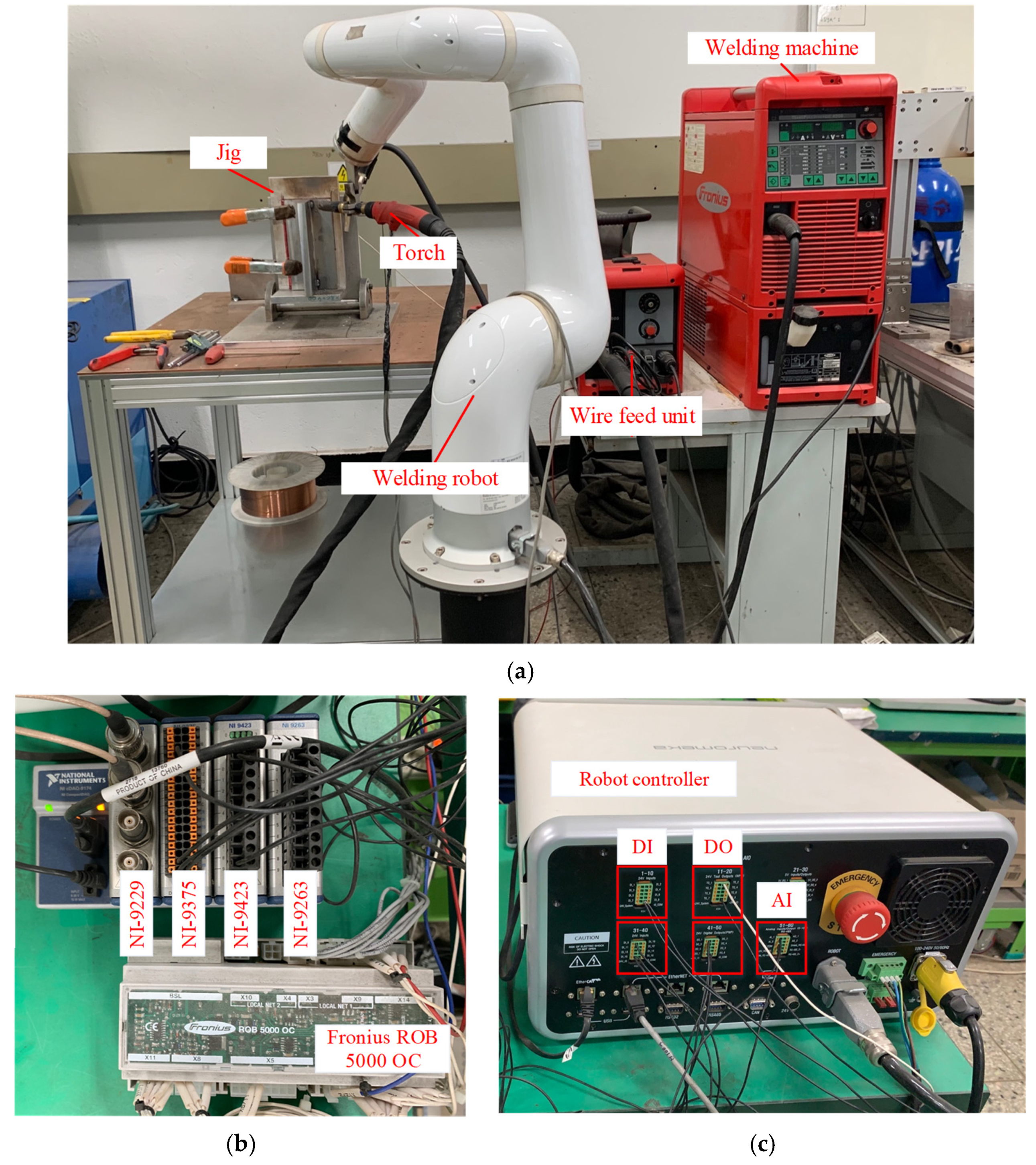
Metals 11 01135 g001
Figure 2. Experimental equipment: (a) welding robot and welding machine, (b) NI modules and ROB 5000 OC, and (c) robot controller.
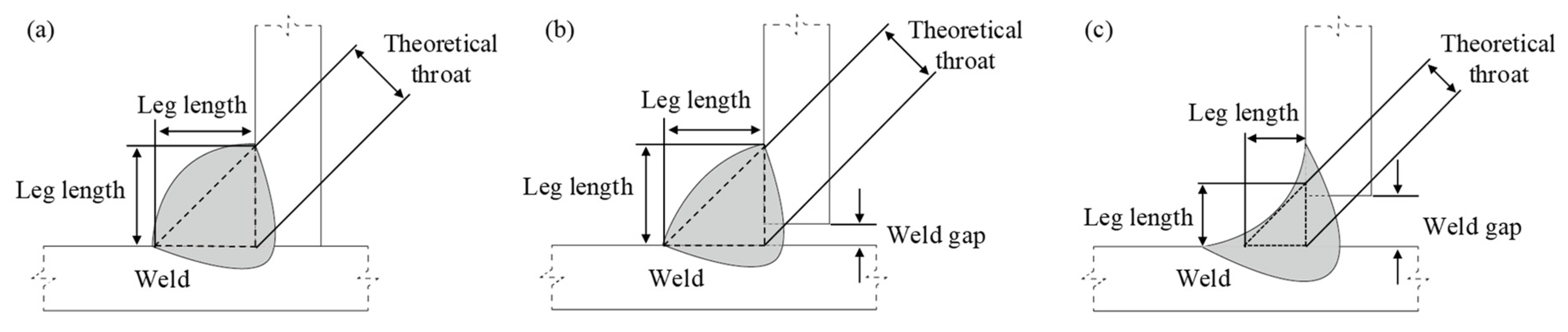
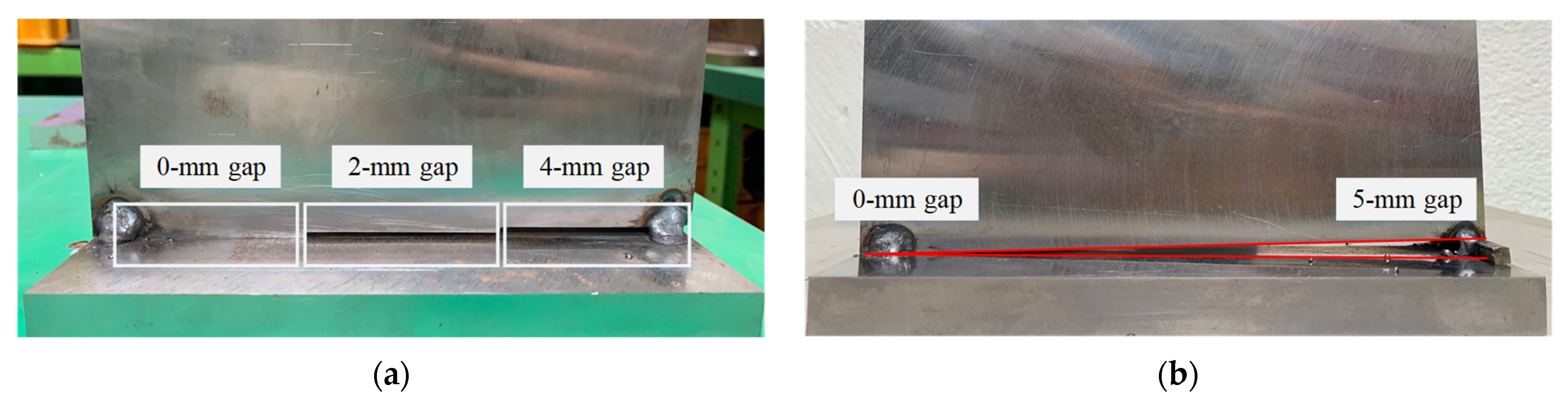
Metals 11 01135 g002
Figure 3. Welded bead shape quality parameters on the T-joint: (a) without weld gap and (b,c) with weld gap.
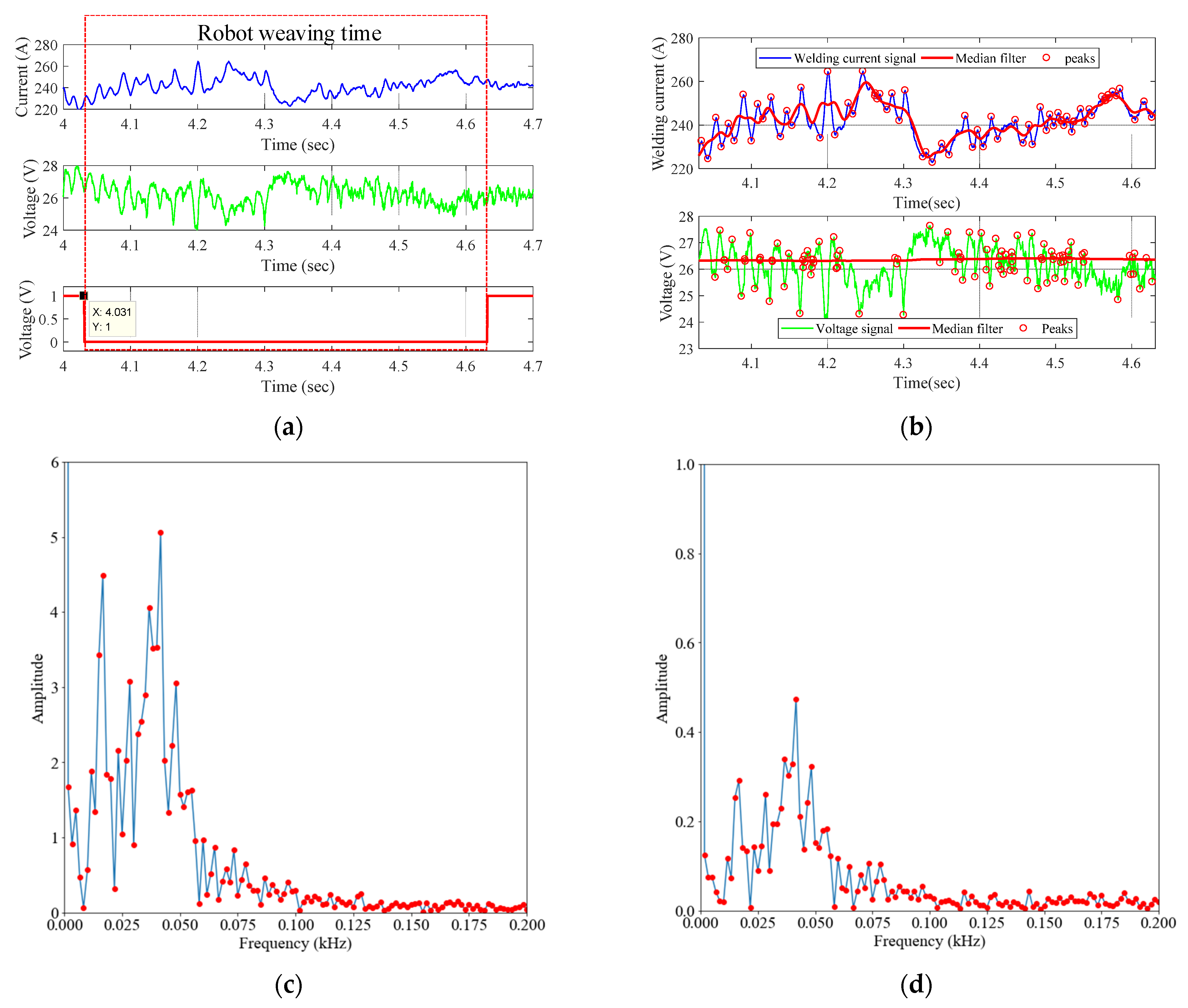
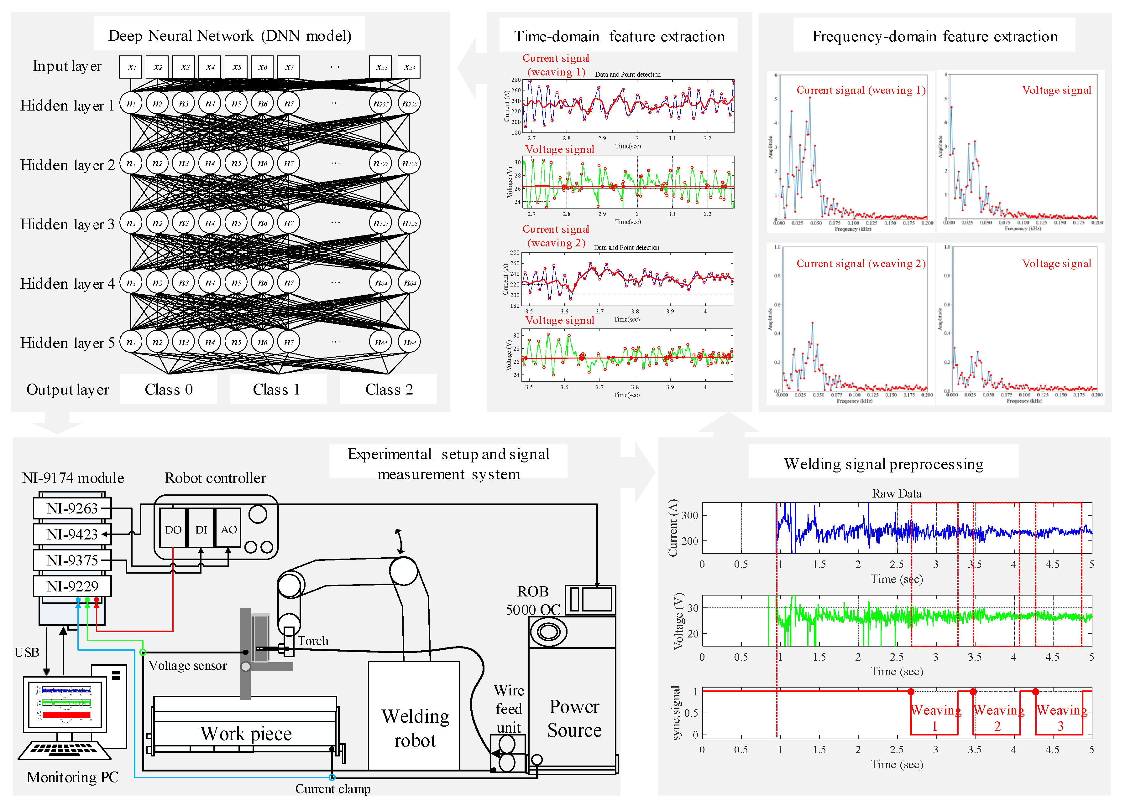
Metals 11 01135 g003
Figure 4. Time and frequency domain feature extraction: (a) raw data of the welding current and voltage signal, (b) feature point generation using the median filter, (c) FFT result of the welding current signal, and (d) FFT result of the voltage signal.
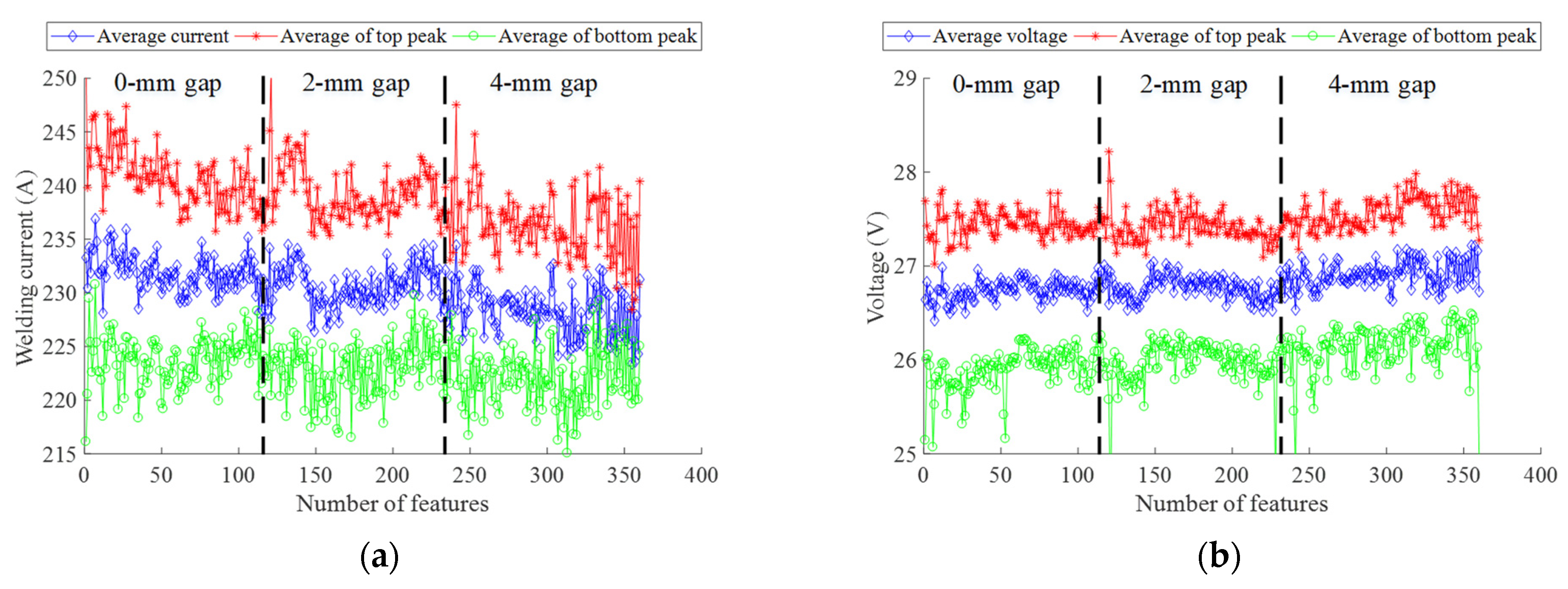
Metals 11 01135 g004
Figure 5. Time domain feature variable visualization: (a) distribution of current feature variables according to the weld gap change and (b) distribution of voltage feature variables according to the weld gap change.
Metals 11 01135 g005
Figure 6. Proposed weld gap detection and welding quality control system.
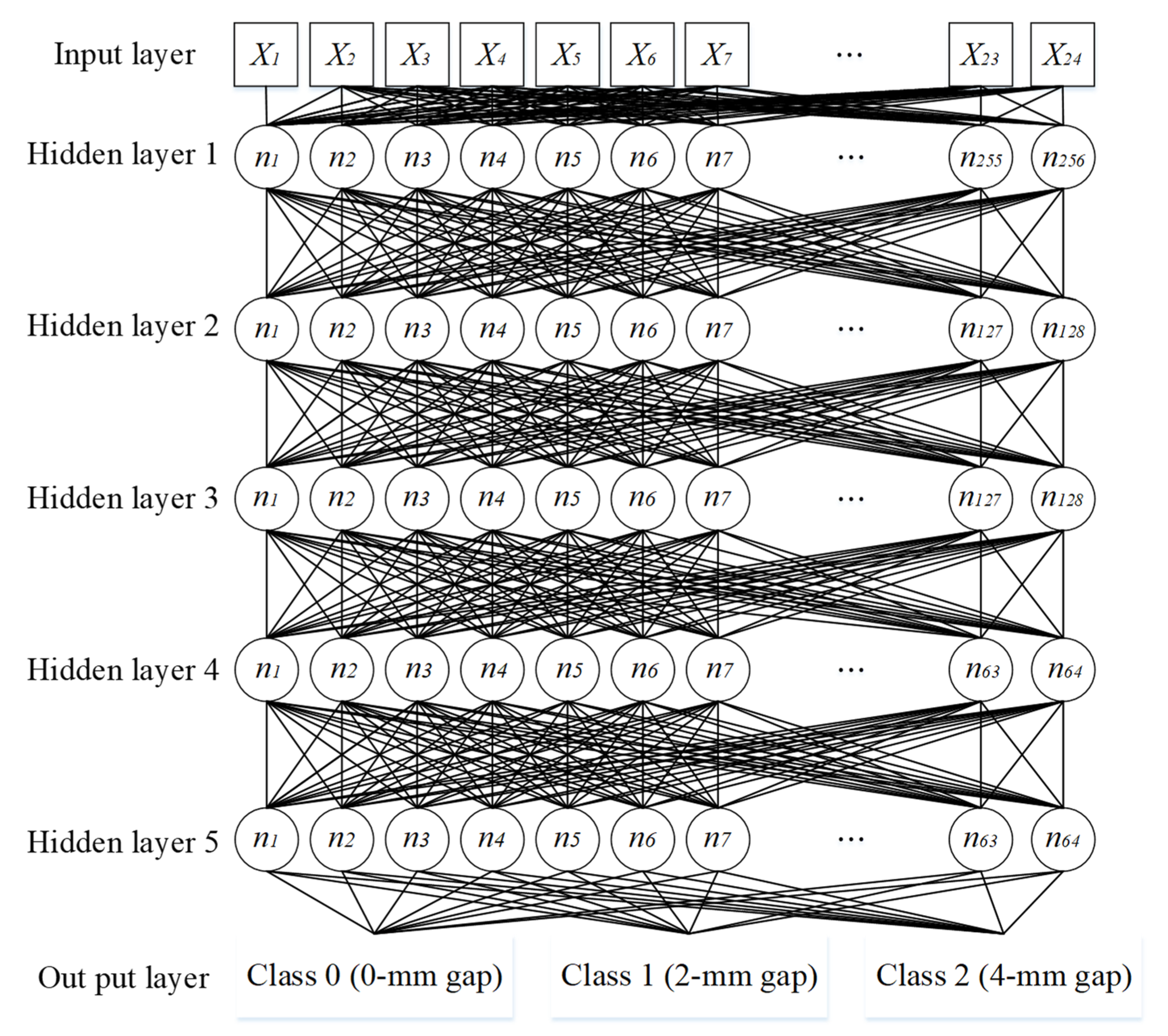
Metals 11 01135 g006
Figure 7. Structure of the deep neural network (DNN) for classification of the weld gap.
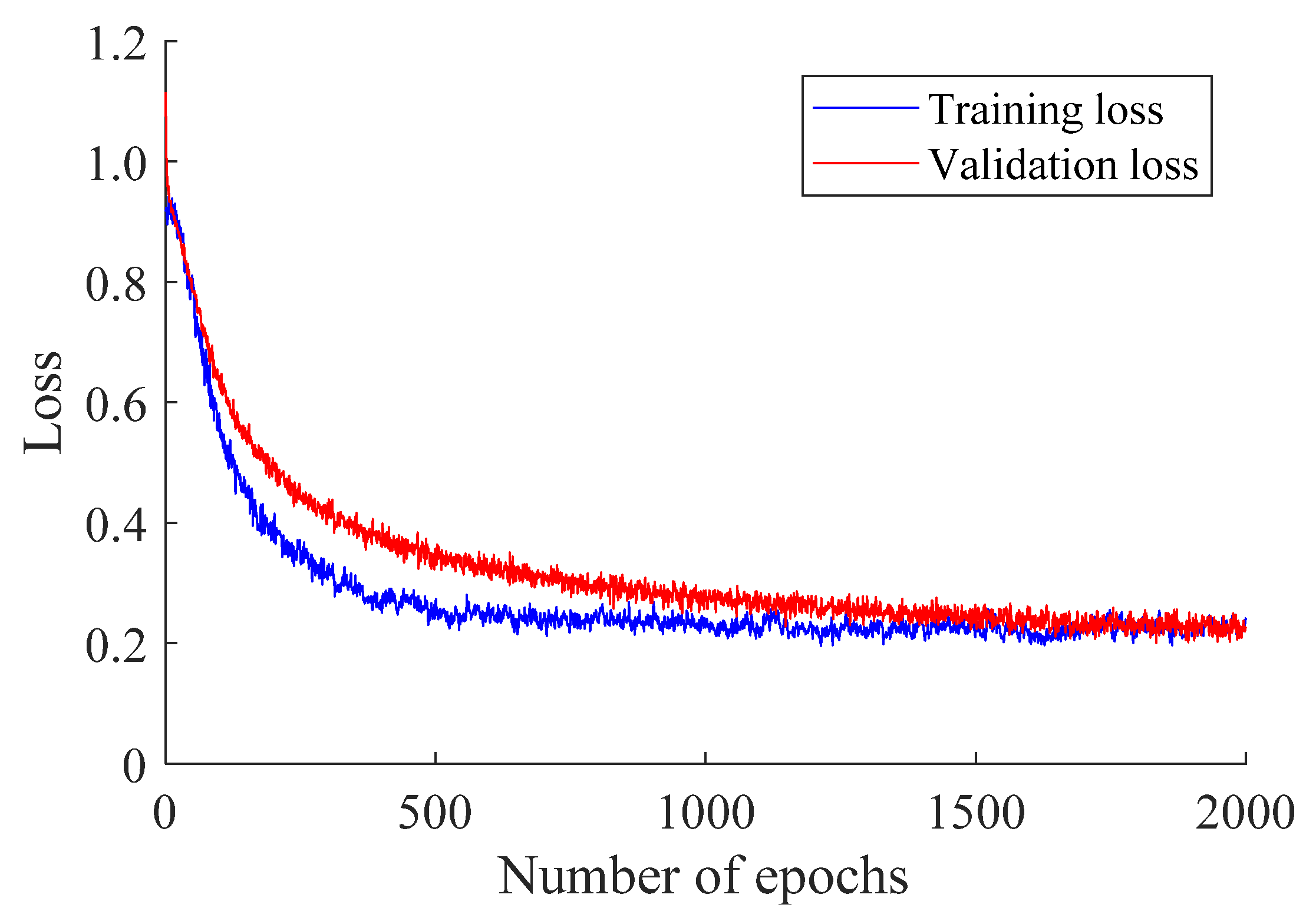
Metals 11 01135 g007
Figure 8. Training results of the proposed DNN model.
Metals 11 01135 g008
Figure 9. Frame designation of welding current data: (a) the test plate used for offline verification and (b) the test plate used for online verification.
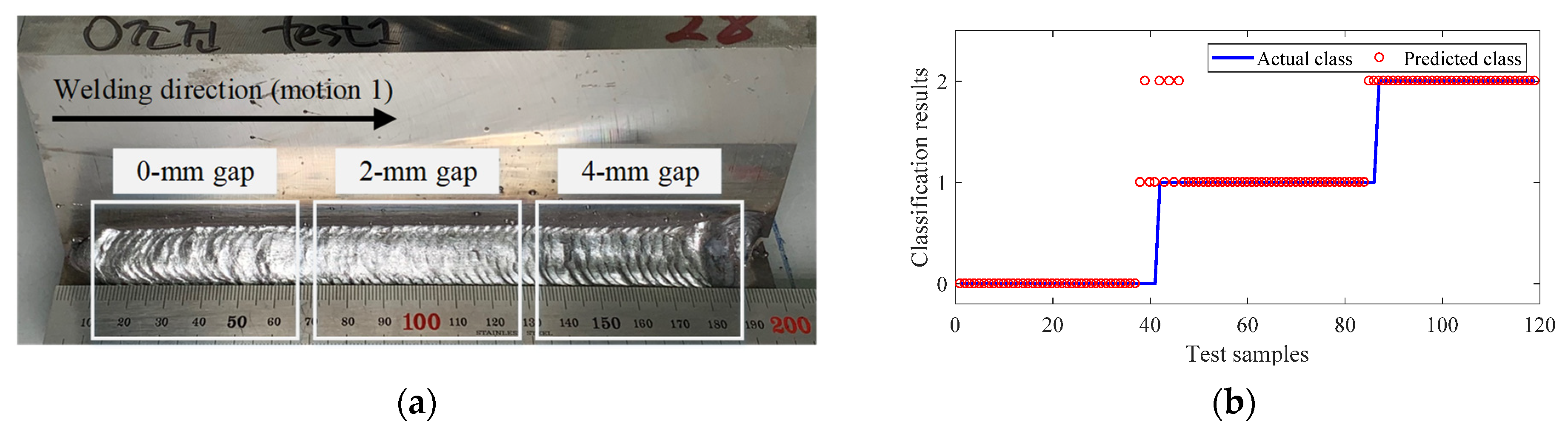
Metals 11 01135 g009
Figure 10. Offline verification results for optimal conditions for 0 mm gap (applied robot motion 1): (a) weld bead shape of each weld gap region and (b) weld gap classification results.
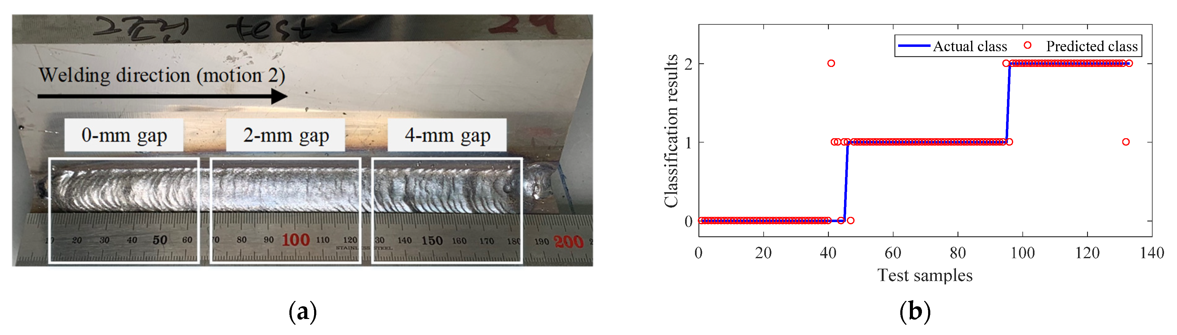
Metals 11 01135 g010
Figure 11. Offline verification results for optimal conditions for 2 mm gap (applied robot motion 2): (a) weld bead shape of each weld gap region and (b) weld gap classification results.
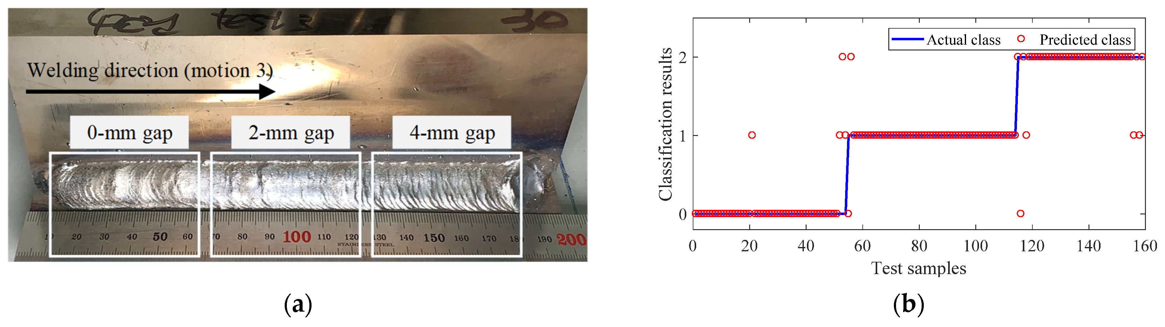
Metals 11 01135 g011
Figure 12. Offline verification results for optimal conditions for 4 mm gap (applied robot motion 3): (a) weld bead shape of each weld gap region and (b) weld gap classification results.
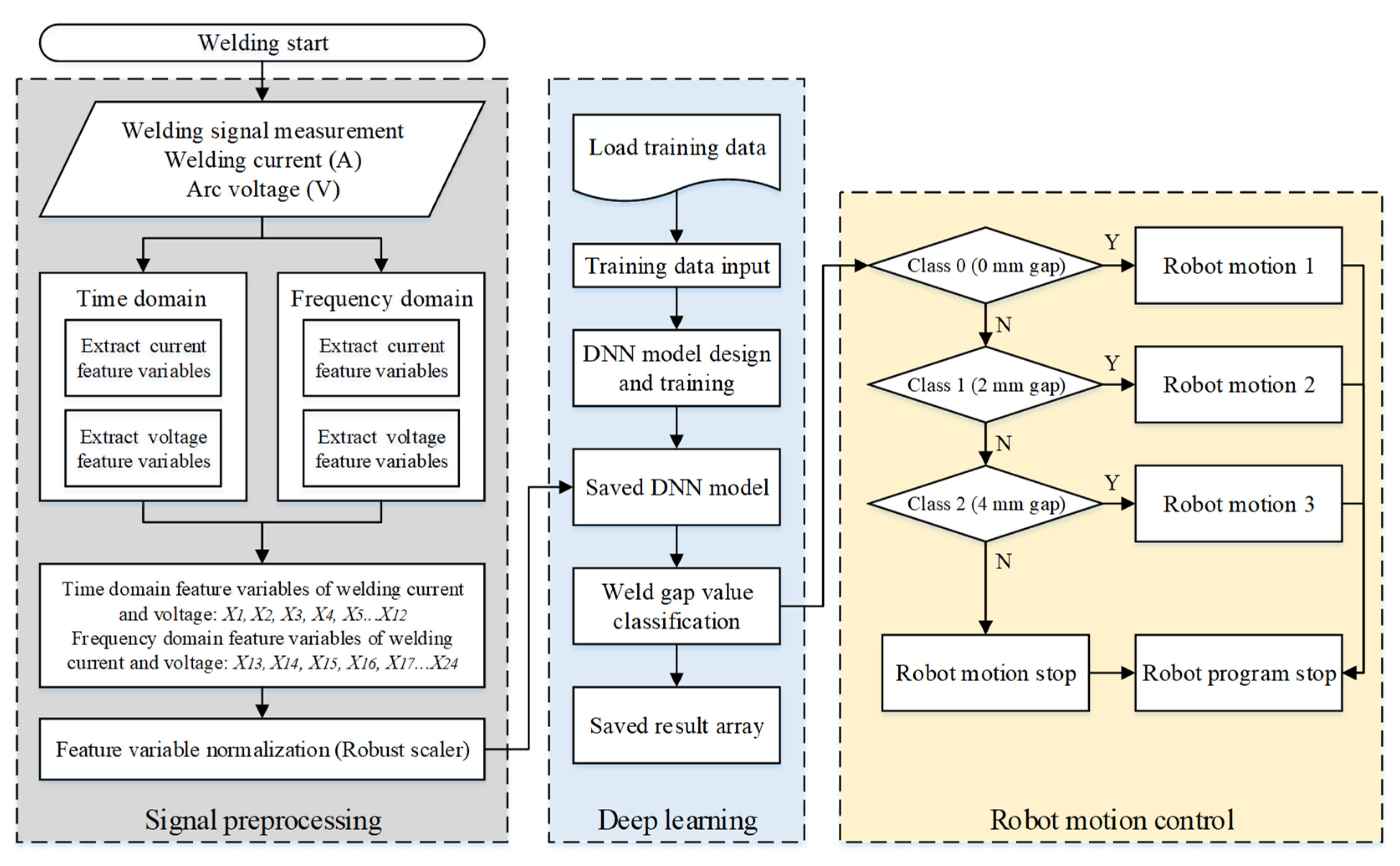
Metals 11 01135 g012
Figure 13. Flowchart of the technical roadmap.
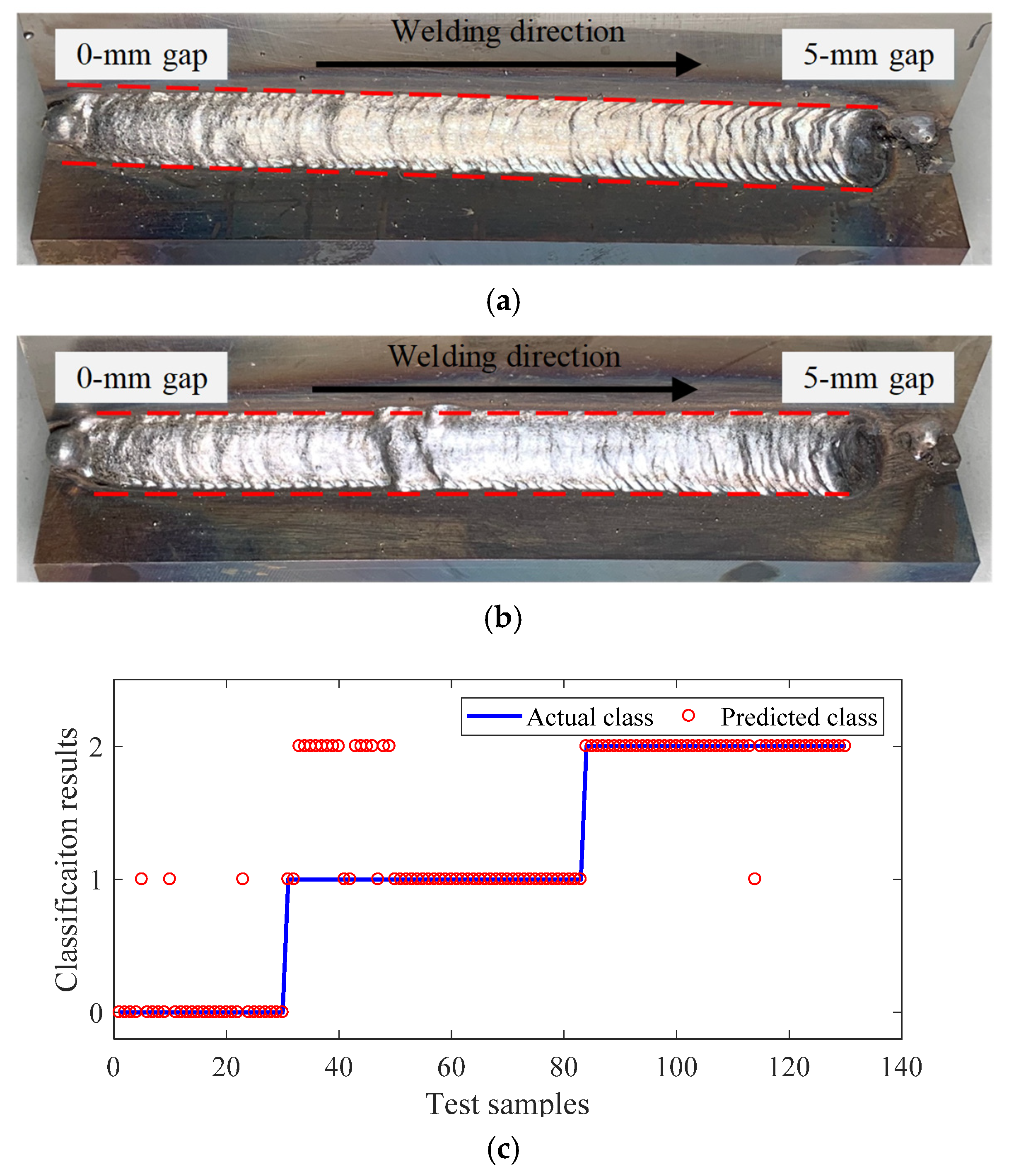
Metals 11 01135 g013
Figure 14. Online weld gap monitoring and robot control results (applied robot motion 1): (a) weld bead shape of linearly increasing gap regions (without robot control), (b) weld bead shape of linearly increasing gap regions (with robot control), and (c) real-time weld gap monitoring results.
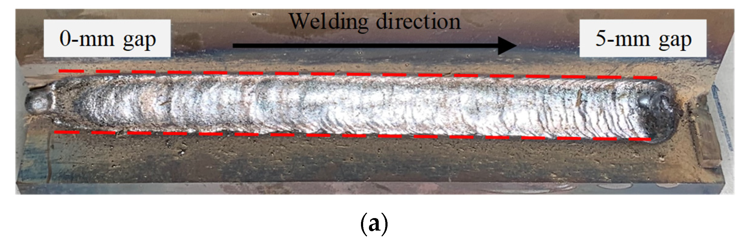
Metals 11 01135 g014
Figure 15. Online weld gap monitoring and robot control results (applied robot motion 3): (a) weld bead shape of linearly increasing gap regions (without robot control), (b) weld bead shape of linearly decreasing gap regions (with robot control), and (c) real-time weld gap monitoring results.
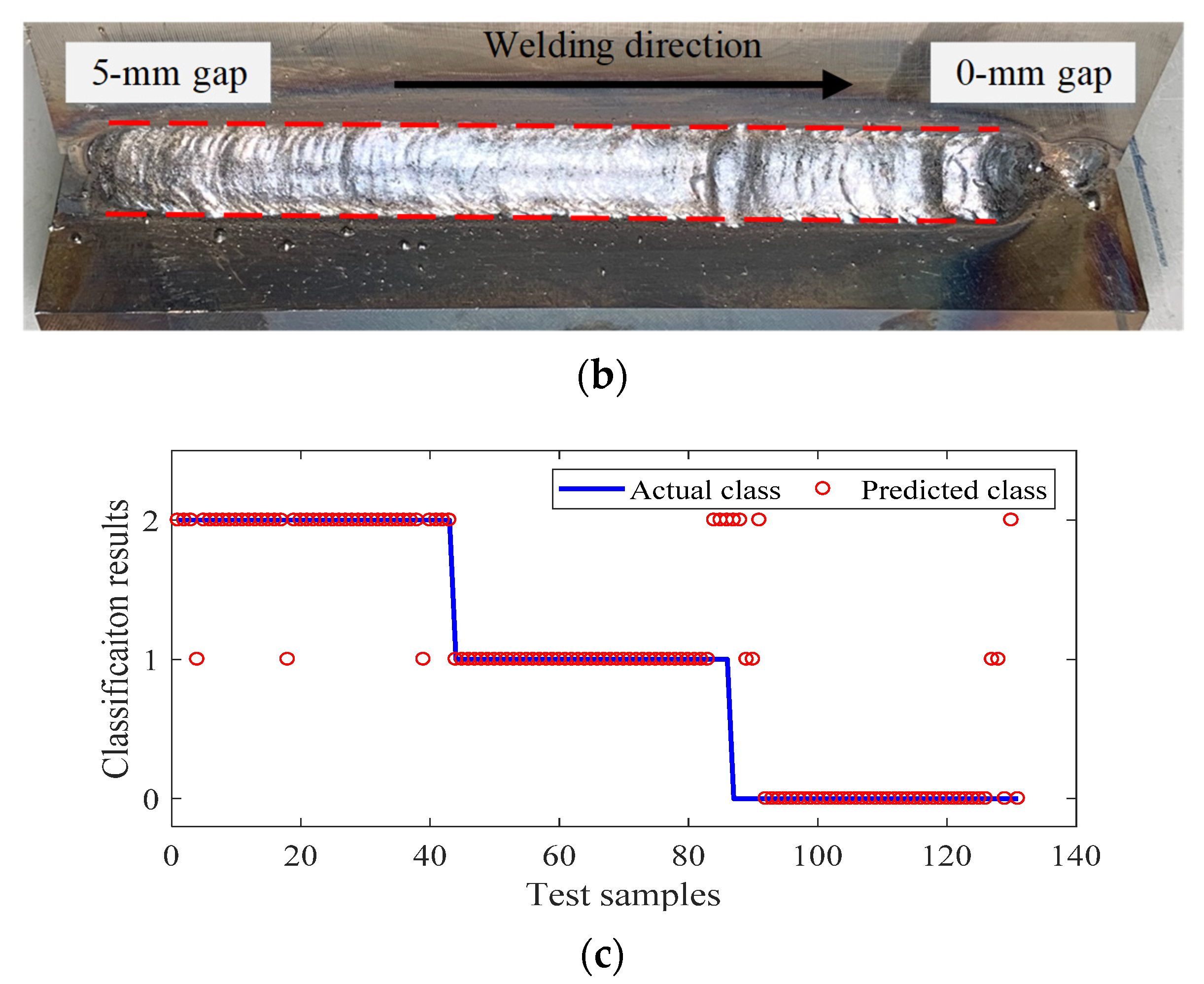
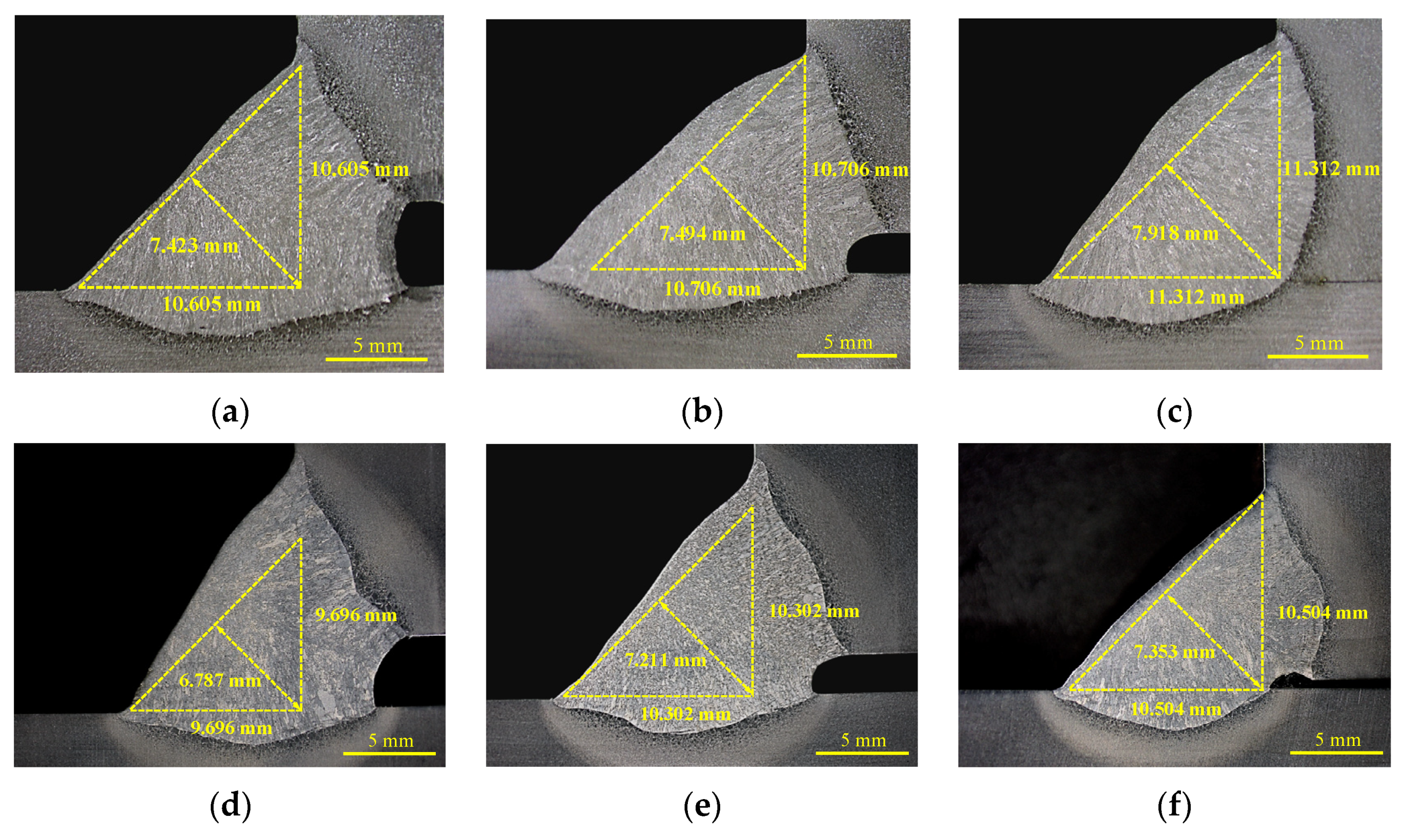
Metals 11 01135 g015aMetals 11 01135 g015b
Figure 16. Weld bead cross-sectional comparison with and without quality control (optimal conditions for 0 mm gap): (ac) without real-time weld quality control, and (df) with weld quality control based on the proposed DNN method.
Metals 11 01135 g016
Figure 17. Weld bead cross-sectional comparison with and without quality control (optimal conditions for 4 mm gap): (ac) without real-time weld quality control, and (df) with weld quality control based on the proposed DNN method.
Metals 11 01135 g017
Table 1. Chemical composition and mechanical properties of the base metal.
Chemical Composition (wt%)Mechanical Properties
SS 400CSiMnPSYP
(MPa)
TS
(MPa)
EI
(%)
0.17440.2520.7730.01270.003728145726
Table 2. Welding experiment conditions.
Welding ParameterParameter Value
Welding typeFCAW
Welding speed (cm/min)10.8, 13.2, 16.0
CTWD (mm)18
Wire feed rate (m/min)6.8
Welding voltage (V)29
Welding jointT-fillet joint
Shield gasCO2-100% (25 L/min)
Weld gap (mm)0, 2, 4
Weaving speed (Hz)0.9
Weaving width (mm)9
Torch work angle (°)45
Table 3. Weld bead cross-sectional analysis.
Robot MotionWeld Gap (mm)
024
Motion 1 Metals 11 01135 i001 Metals 11 01135 i002 Metals 11 01135 i003
Motion 2 Metals 11 01135 i004 Metals 11 01135 i005 Metals 11 01135 i006
Motion 3 Metals 11 01135 i007 Metals 11 01135 i008 Metals 11 01135 i009
Table 4. Definitions of feature variables.
Feature Variable NumberDescriptionSymbol
X1Average welding current value in one weaving section I ¯
X2Average of bottom peak value (current) I ¯ ( P b )
X3Standard deviation of bottom peak value (current) s [ I ( P b ) ]
X4Average of top peak value (current) I ¯ ( P t )
X5Average value of top to bottom peak with respect to median filter I ¯ f
X6Average value of bottom to top peak with respect to median filter I ¯ r
X7Average voltage value in one weaving section V ¯
X8Average of bottom peak value (voltage) V ¯ ( P b )
X9Standard deviation of bottom peak value (voltage) s [ V ( P b ) ]
X10Average of top peak value (voltage) V ¯ ( P t )
X11Average value of top to bottom peak with respect to median filter V ¯ f
X12Average value of bottom to top peak with respect to median filter V ¯ r
X13Maximum value of current frequency m a x ( f c )
X14Average value of current frequency f c ¯
X15Standard deviation value of current frequency s ( f c )
X16Maximum amplitude (current frequency) m a x ( A c )
X17Average value of amplitude A c ¯
X18Standard deviation value of amplitude s ( A c )
X19Maximum value of voltage frequency m a x ( f V )
X20Average value of voltage frequency f V ¯
X21Standard deviation value of voltage frequency s ( f V )
X22Maximum amplitude (voltage frequency) m a x ( A V )
X23Average value of amplitude A V ¯
X24Standard deviation value of amplitude s ( A V )
Table 5. Five DNN structures.
DNN StructureInput NodeHidden LayerNumber of NodesTraining Accuracy (%)Training LossValidation Accuracy (%)Validation Loss
Structure 124564-64-64-64-6488.60.4283.60.51
Structure 25128-128-128-128-12890.20.25880.29
Structure 35256-128-128-64-6494.30.15920.22
Structure 44256-128-128-6489.50.36850.44
Structure 54128-128-64-6488.40.39810.48
Table 6. Training network structure of the DNN used in this study (structure 3).
Layer NumberTypeOutput ShapeNumber of ParametersArguments
-Input24 Range = [0,1,2]
1Dense_12566400
2Batch Normalization_12561024
3Activation_1256 Function = ReLU
4Dropout_1256 Probability = 0.5
5Dense_212832896
6Batch Normalization_2128512
7Activation_2128 Function = ReLU
8Dropout_2128 Probability = 0.5
9Dense_312816512
10Batch Normalization_3128512
11Activation_3128 Function = ReLU
12Dropout_3128 Probability = 0.5
13Dense_4648256
14Batch Normalization_464256
15Activation_464 Function = ReLU
16Dropout_464 Probability = 0.5
17Dense_5644160
18Batch Normalization_564256
19Activation_564 Function = ReLU
20Dropout_564 Probability = 0.5
21Dense_63195Function = Softmax
22Batch Normalization_6312
23Activation_63 Function = ReLU
Table 7. Weld gap monitoring performance of the proposed DNN model.
Welding Speed (cm/min)OutputSupportCorrectly
Estimated
ErrorAccuracy %Average Accuracy %
16 (motion 1)Class 0 3834489.592.8
Class 1 4540588.9
Class 2 36360100
13.2 (motion 2)Class 0 4743491.594.1
Class 1 4846295.8
Class 2 3937294.9
10.8 (motion 3)Class 0 5450492.694.07
Class 1 5958198.3
Class 2 4642491.3
Table 8. Real-time weld gap detection performance of the proposed DNN model (increasing gap).
VariableSupportCorrectly
Estimated
ErrorAccuracy %Average Accuracy %
Class 0 (0 mm gap)302739086
Class 1 (2 mm gap)53371669.8
Class 2 (4 mm gap)4746197.9
Table 9. Real-time weld gap detection performance of the proposed DNN model (decreasing gap).
VariableSupportCorrectly EstimatedErrorAccuracy %Average Accuracy %
Class 0 (0 mm gap)434039389.4
Class 1 (2 mm gap)4340393
Class 2 (4 mm gap)4537882.2
Table 10. Comparison thickness of theoretical throat with and without control (Optimal conditions for 0 mm gap).
Thickneass of Theoretical Throat (mm)Weld Gap (mm)
024
Without control7.3536.9286.363
With control7.6237.4947.706
Table 11. Comparison thickness of theoretical throat with and without control (Optimal conditions for 4 mm gap).
Thickneass of Theoretical Throat (mm)Weld Gap (mm)
420
Without control7.3536.9286.363
With control7.6237.4947.706
Publisher’s Note: MDPI stays neutral with regard to jurisdictional claims in published maps and institutional affiliations.

