1. Introduction
Additive manufacturing (AM) has received more attention and application in the manufacturing industry recently. However, wire and arc additive manufacturing (WAAM) is more suitable for manufacturing complex components than an electron beam and laser [
1]. At the same time, it has the advantages of low equipment and operational costs, and high material utilization rate and cladding efficiency [
2]. Therefore, WAAM based on gas metal arc welding (GMAW) has become the research focus of many scholars and institutions in China and abroad. Zhang et al. [
3] carried out a preliminary study of GMAW rapid formation, while Jiang et al. [
4] developed a cold metal transfer (CMT) deposition method for manufacturing aluminum alloy. The results of the above studies showed that back-and-forth depositing could reduce the heat accumulation and difference of two endings, and thereby improving the forming efficiency and reducing roughness. Furthermore, Montevecchi et al. [
5] employed a GMAW method to manufacture H08Mn2Si deposited samples and research the influence of cooling time on the morphology. The above studies indicated that WAAM based on GMAW could manufacture the metal parts and different parameters had an effect on the morphology.
In recent years, countless scholars have done researches on stainless steel arc additive manufacturing. Wang et al. [
6] studied the quality of 316L stainless steel by two modes of high-speed pulse and high-speed arc. The results showed that the high-speed arc had higher tensile strength and hardness than the high-speed pulse because of its lower heat input and finer crystal structure, while Chen et al. [
7] made a 316L austenitic stainless steel part with high power metal inert gas (MIG) arc AM and found that with the increase of arc power, the tensile strength, yield strength and area reduction of 316 samples decreased. In addition, Xiao et al. [
8] studied the effect of thermal behavior on its microstructure evolution in tungsten inert gas (TIG) arc additive manufacturing of 316L stainless steel. In the process of microstructure evolution in the non-equilibrium state of heat accumulation, the increasing heat accumulation made the undercooling change during solidification, and the microstructure of the lower deposition layer gradually changed from skeleton ferrite to dendrite. Furthermore, Wang et al. [
9] prepared 316L austenitic stainless steel by CMT. It was found that the remelting zone had higher ferrite content and smaller austenite dendrite size, and more dispersed orientation and lower residual stress than the overlapping zone. Similarly, Su et al. [
10] used the solidification mode of austenitic stainless steel to predict the microstructure of additive manufacturing. The results showed that the predicted microstructure was consistent with the actual microstructure, which was dendritic austenite, lath ferrite and skeletal ferrite, and the microhardness of the lower part was higher than that of the upper part. While Wang et al. [
11] have formed 316L austenitic stainless steel thin-walled parts by the CMT arc additive manufacturing method. The microstructure of the parts was γ-Fe and δ-ferrite, and the morphology of δ-ferrite was dendritic and vermicular. The microhardness results showed that there was little change in the hardness perpendicular to and parallel to the deposition direction, which was related to the uniformity of the microstructure formed in all directions.
Although using the same average current, different welding current processes cause different current waveforms, voltages, and wire feeding speed; that is, the thermal input is altered, which can further influence the forming and performance of the deposition. In reference [
12], ER70S-6 mild steel was built by means of direct current MIG, cold metal transfer (CMT), CMT advanced polarity and CMT continuous trajectory welding. The morphology, microstructure, and hardness of deposition were analyzed, and then the tensile properties were estimated. The results revealed that CMT continuous trajectory deposition was the best in forming and properties. Rodriguez et al. [
13] performed depositions of 316L using continuous and pulse current by CMT and top tungsten inert gas welding and compared the forming efficiency and surface roughness. The results showed that pulse current was better than other welding, which had higher molding efficiency and required tensile properties.
Through the previous analysis study of weld morphology, Yao et al. [
14,
15,
16] got a visual understanding of the welding quality, then Wu et al. [
17,
18] found that the morphology of the part could be improved by asynchronous arc starting and extinguishing. Moreover, Liu et al. [
19] studied the influence of arc AM process parameters on the forming quality through an orthogonal experiment. The results showed that the cooling between passes was sufficient and the overlapping parts were obviously divided, which lead the hardness on both sides of the weld bead to be high, whereas on the incomplete recrystallization area, it was low. Lin et al. [
20] studied the influence of welding speed and interlayer cooling time on the morphology of the AM, and found that the welding speed had a more obvious influence on the morphology. When the interlayer cooling time reached a certain value, the interlayer temperature was constant, and the morphology changed little.
The duty ratio in double-pulse waveform means the percentage of a high level in a pulse period. This means that the peak time is different as well as the duty cycle in a constant period. In other words, the average current in a period is different, which finally affects the heat input. However, there are few researches on 316L stainless steel additive manufacturing with different duty ratios of the MIG welding double-pulse. Therefore, in this paper, a comparative study of double-pulse enhanced welding with different pulse duty ratios and a single-pulse of stainless steel additive manufacturing was proposed by a robot-manufacturing platform. Then the influence of a double-pulse and duty ratio process on the additive manufacturing molding, microstructure, microhardness and tensile properties was analyzed. This study will provide an alternative additive manufacturing process for grain refinement and performance improvement and lay a foundation for further research and application of double-pulse welding arc additive manufacturing.
Author Contributions
Methodology, P.Y.; writing—original draft preparation, H.L. and W.W.; project administration and funding acquisition, P.Y.; data curation, H.L. and H.T.; writing—review and editing, providing ideas, P.Y. and W.W. All authors have read and agreed to the published version of the manuscript.
Funding
This research was funded by the National Natural Science Foundation Project of China, grant number 51805099; Project of Educational Commission of Guangdong Province of China, grant number 2020ZDZX2019; Guangzhou Science and Technology Plan Project, grant number 201805010001.
Institutional Review Board Statement
Not applicable.
Informed Consent Statement
Not applicable.
Data Availability Statement
Not applicable.
Conflicts of Interest
The authors declare no conflict of interest.
References
- Harris, M.; Potgieter, J.; Archer, R.; Arif, K.M. In-Process Thermal Treatment of Polylactic Acid in Fused Deposition Modelling. Mater. Manuf. Processes. 2019, 34, 701–713. [Google Scholar] [CrossRef]
- Xiong, J.; Li, R.; Lei, Y.; Chen, H. Heat propagation of circular thin-walled parts fabricated in additive manufacturing using gas metal arc welding. J. Mater. Process. Technol. 2019, 251, 12–19. [Google Scholar] [CrossRef]
- Zhang, Y.; Chen, Y.; Li, P.; Male, A.T. Weld deposition-based rapid prototyping: A preliminary study. J. Mater. Process. Technol. 2003, 135, 347–357. [Google Scholar] [CrossRef]
- Jiang, Y.L. Research on the Rapid Prototyping Technology and Forming Process of Aluminum Alloy Based on the CMT. Master’s Thesis, Harbin Institute of Technology, Harbin, China, 2013. [Google Scholar]
- Montevecchi, F.; Venturini, G.; Grossi, N.; Scippa, A.; Campatelli, G. Idle times selection for wire arc additive manufacturing: A finite element based technique. Addit. Manuf. 2018, 21, 479–486. [Google Scholar] [CrossRef]
- Wang, L.; Xue, J.; Wang, Q. Correlation between arc mode, microstructure, and mechanical properties during wire arc additive manufacturing of 316 L stainless steel. Mater. Sci. Eng. 2019, 751, 183–190. [Google Scholar] [CrossRef]
- Chen, X.; Zhang, S.; Ran, X.; Huang, Z. Effect of arc power on microstructure and mechanical properties of austenitic stainless steel 316L fabricated by high efficient arc additive manufacturing. Trans. China Weld. Inst. 2020, 41, 42–49. [Google Scholar]
- Xiao, X.; Yin, Y.; Li, C.; Li, C.; Zhang, K. Influence of thermal behavior on microstructure evolution of TIG arc additive manufacture for 316L stainless steel. Trans. Mater. Heat. Treat. 2020, 41, 97–105. [Google Scholar]
- Wang, C.; Liu, T.; Zhu, P.; Lu, Y.H.; Shoji, T. Study on microstructure and tensile properties of 316 L stainless steel fabricated by CMT wire and arc additive manufacturing. J. Mater. Sci. Eng. A 2020, 796, 140006. [Google Scholar] [CrossRef]
- Su, F.; Ma, C.; Zhang, T.; Ming, C. Research on Microstructure and High Temperature Mechanical Properties of 304 L Austenitic Stainless Steel Made by Arc Additive Manufacturing. Hot. Work. Tech. 2019, 48, 70–74. [Google Scholar]
- Wang, X.; Liu, F.; Fang, P.; Wu, S. Forming accuracy and properties of wire arc additive manufacturing of 316 L components using CMT process. Tran. China Weld. Inst. 2019, 40, 100–106. [Google Scholar]
- Prado-Cerqueira, J.L.; Camacho, A.M.; Dieguez, J.L.; Rodriguez-Prieto, A.; Aragon, A.M.; Lorenzo-Martin, C.; Yanguas-Gil, A. Analysis of Favorable Process Conditions for the Manufacturing of Thin-Wall Pieces of Mild Steel Obtained by Wire and Arc Additive Manufacturing (WAAM). Materials 2018, 11, 1449. [Google Scholar] [CrossRef] [Green Version]
- Rodriguez, N.; Vázquez, L.; Huarte, I.; Arruti, E.; Tabernero, I.; Alvarez, P. Wire and Arc Additive Manufacturing: A Comparison Between CMT and TopTIG Processes Applied to Stainless Steel. Weld. World 2018, 62, 1083–1096. [Google Scholar] [CrossRef]
- Yao, P.; Zhou, K.; Huang, S. Process and Parameter Optimization of the Double-Pulsed GMAW Process. Metals 2019, 9, 1–22. [Google Scholar] [CrossRef] [Green Version]
- Yao, P.; Zhou, K.; Tang, H. Effects of Operational Parameters on the Characteristics of Ripples in Double-Pulsed GMAW Process. Materials 2019, 12, 2767. [Google Scholar] [CrossRef] [PubMed] [Green Version]
- Yao, P.; Zhou, K.; Lin, H.; Xu, Z.; Yue, S. Exploration of Weld Bead Forming Rule during Double-Pulsed GMAW Process Based on Grey Relational Analysis. Materials 2019, 12, 3662. [Google Scholar] [CrossRef] [Green Version]
- Wu, W.; Xue, J.; Zhang, Z.; Ren, X.; Xie, B. Process Optimization on Multilayer Morphology During 316 L Double-wire CMT+P Deposition Process. Metals 2019, 9, 1334. [Google Scholar] [CrossRef] [Green Version]
- Wu, W.; Xue, J.; Zhang, Z.; Yao, P. Comparative study of 316 L depositions by two welding current processes. Mater. Manuf. Process. 2019, 34, 1502–1508. [Google Scholar] [CrossRef]
- Liu, D.; Lv, Y.; Yang, H.; Zhou, W.; Yuan, F. Effect of Arc Additive Process Parameters on Forming Quality. Mech. Sci. Tech. Aerosp. Eng. 2020, 39, 1412–1418. [Google Scholar]
- Lin, H.; Huang, S.; Yao, P.; Wan, X. Influence of Process Parameters on Robot Wire and Arc Additive Manufacturing Forming. J. Netshape. Form. Eng. 2020, 12, 100–106. [Google Scholar]
- Xiong, J. Forming Characteristics in Multi-Layer Single-Bead GMA Additive Manufacturing and Control for Deposition Dimension. Master’s Thesis, Harbin Institute of Technology, Harbin, China, 2014. [Google Scholar]
- Geng, H.; Li, J.; Xiong, J.; Lin, X.; Zhang, F. Geometric Limitation and Tensile Properties of Wire and Arc Additive Manufacturing 5A06 Aluminum Alloy Parts. J. Mater. Eng. Perform. 2016, 26, 621–629. [Google Scholar] [CrossRef] [Green Version]
- Bhattacharya, A.; Shamar, R. Dissimilar Joining Between Austenitic and Duplex Stainless Steel in Double-Shielded GMAW: A Comparative Study. Mater. Manuf. Process. 2016, 31, 300–310. [Google Scholar] [CrossRef]
- Wu, K.; Ding, N.; Yin, T.; Zeng, M.; Liang, Z. Effects of single and double pulses on microstructure and mechanical properties of weld joints during high-power double-wire GMAW. J. Manuf. Process. 2018, 35, 728–734. [Google Scholar] [CrossRef]
- Lin, X.; Huang, W.D. Laser additive manufacturing of high-performance metal components. Sci. Sin. 2015, 45, 1111–1126. [Google Scholar] [CrossRef] [Green Version]
- Standard Specification for Stainless Steel Forgings; ASTM: 100 Barr Harbor Drive, West Conshohocken, PA, USA, 2015.
Figure 1.
Robot arc additive manufacturing platform.
Figure 2.
Schematic diagram of the robot additive manufacturing process.
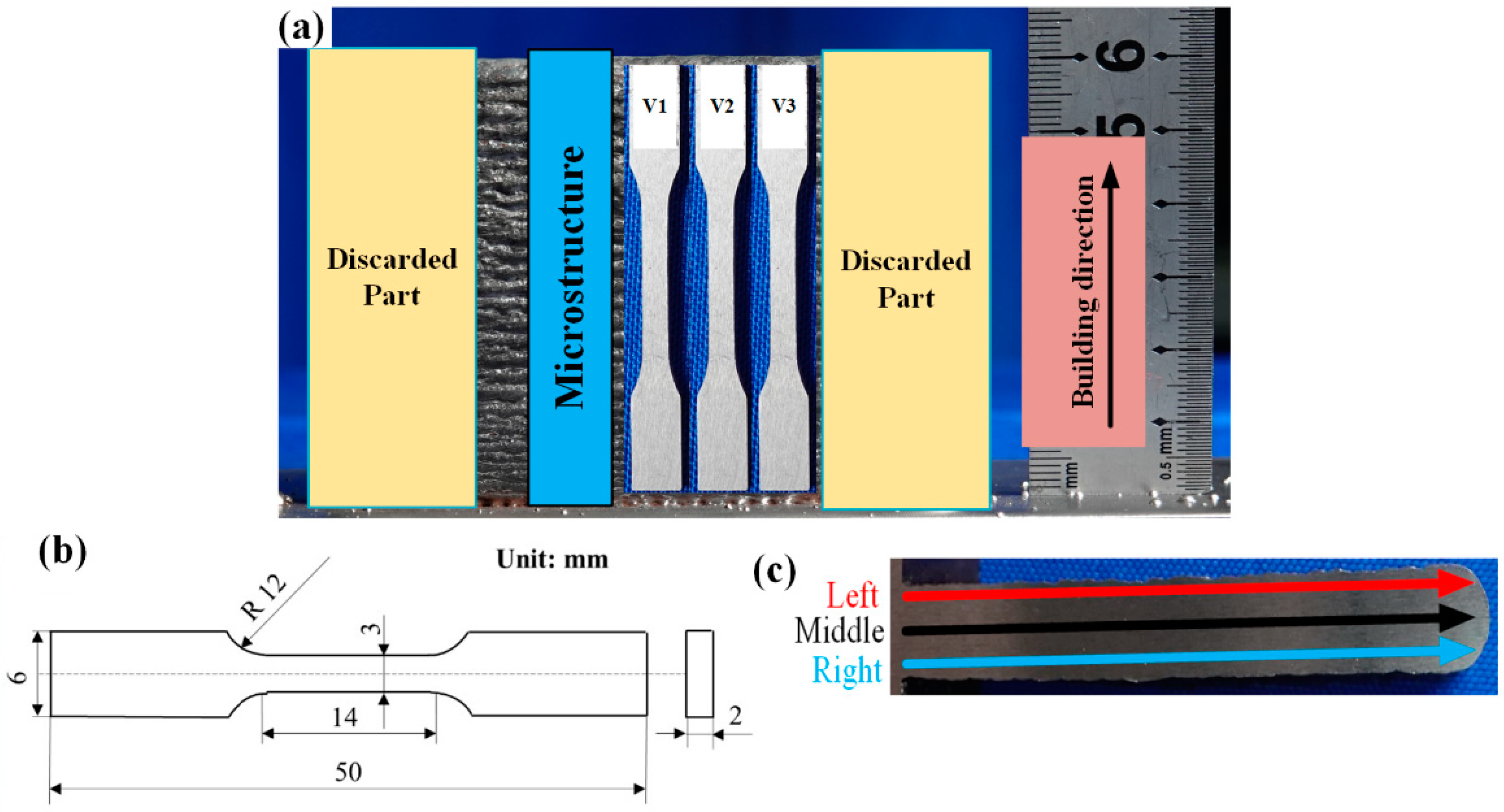
Figure 3.
Sampling size and measuring position: (a) Extraction locations of microstructure and tensile samples on each wall; (b); Tensile specimen sizes; (c) Test position of hardness.
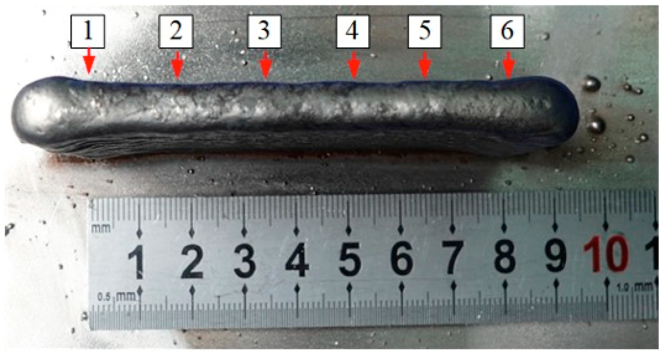
Figure 4.
The schematic diagram of measuring position in the parts: numbers 1 to 6 represent the measuring position of the width and height.
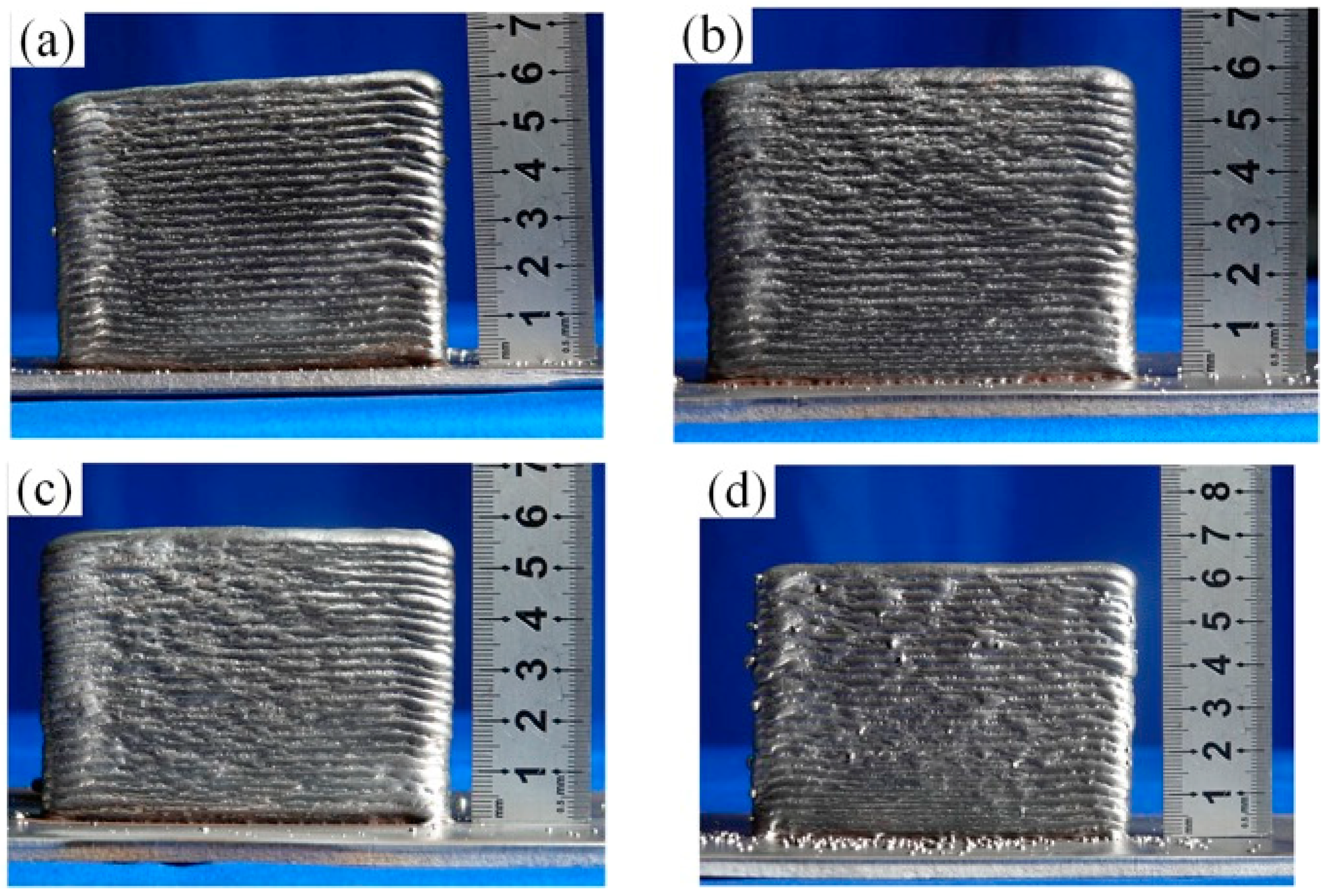
Figure 5.
The morphology of four additive manufacturing walls: (a) deposited part A, (b) deposited part B, (c) deposited part C, (d) deposited part D.
Figure 6.
Six-point heights of four parts.
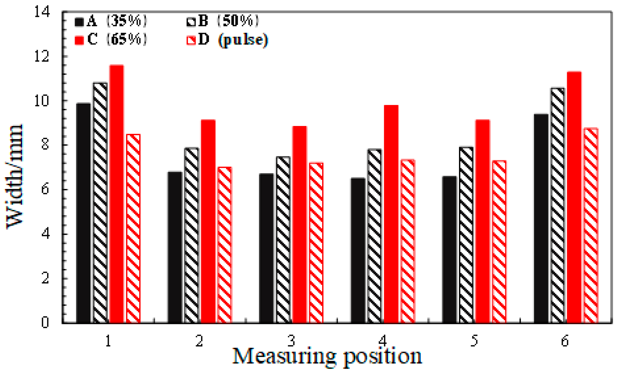
Figure 7.
Six-point widths of four parts.
Figure 8.
Macroscopic metallography of different layers in the middle section of specimen B: (a) layers 1–10, (b) layers 11–20, (c) layers 21–30, (d) layers 31–40, (e) layers 41–50.
Figure 9.
Microstructure of different layers of specimens: (a) specimen A, (b) specimen B, (c) specimen C, (d) specimen D. (a1,a2) layers 41–50, (b1,b2) layers 31–40, (c1,c2) layers 21–30, (d1,d2) layers 11–20, (e1,e2) layers 1–10.
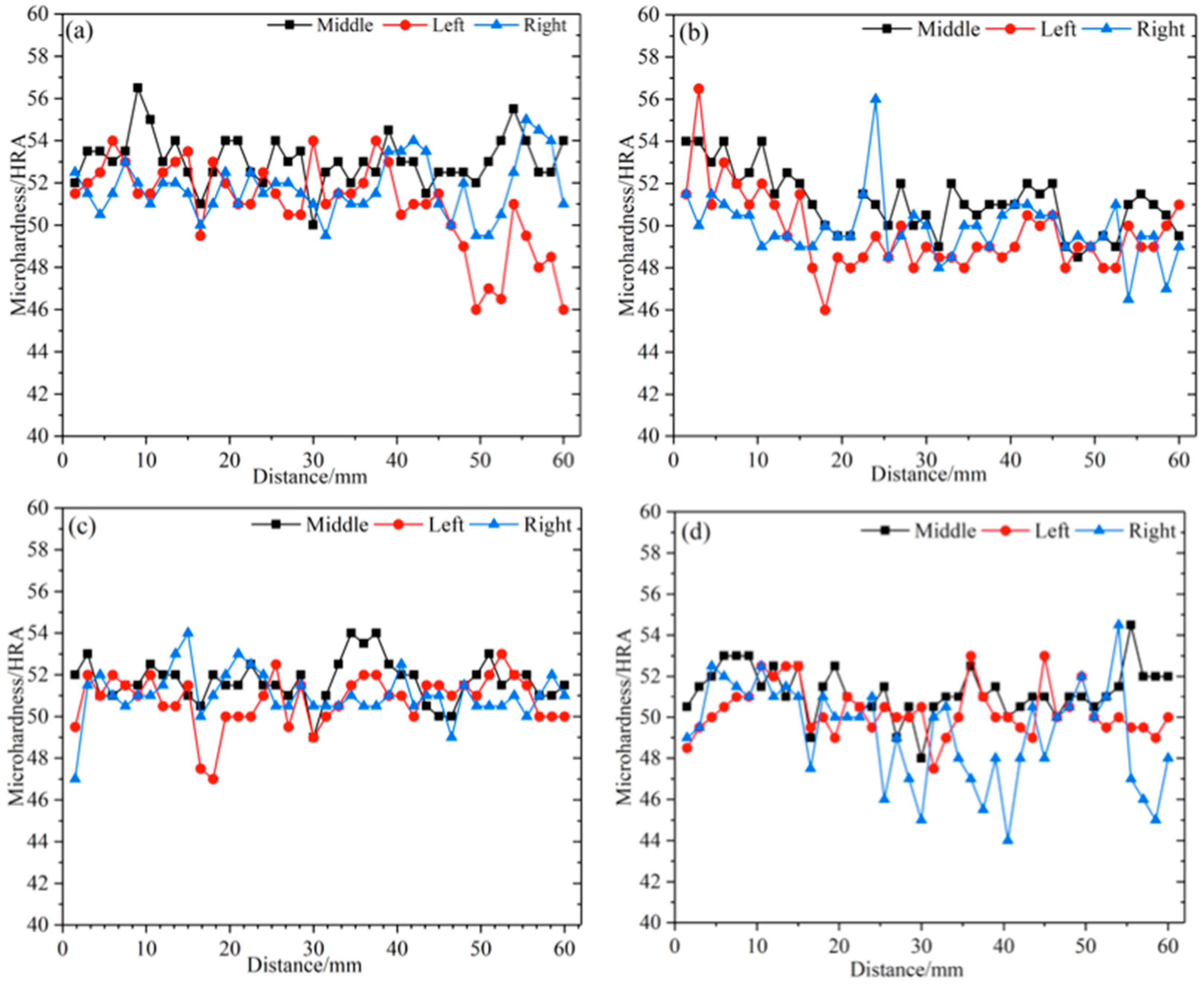
Figure 10.
The hardness curves of four specimens: (a) deposited part A, (b) deposited part B, (c) deposited part C, (d) deposited part D.
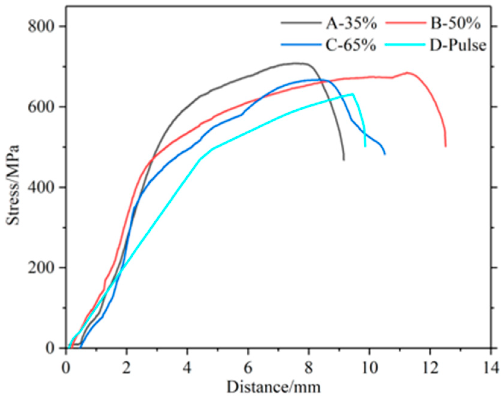
Figure 11.
Stress–displacement curves of four parts.
Table 1.
Chemical composition of the welding wire and substrate (mass fraction, %).
| Material | C | Si | Ni | Cr | Mn | P | Mo | S |
|---|
| 316L | ≤0.03 | ≤1 | 10~14 | 18~20 | ≤2 | ≤0.03 | 2~3 | ≤0.03 |
Table 2.
Forming process parameters of four depositions.
| Number | Current Mode | Average Current (A) | Duty Ratio |
|---|
| A | Double-pulse strengthen | 80 | 35% |
| B | Double-pulse strengthen | 80 | 50% |
| C | Double-pulse strengthen | 80 | 65% |
| D | Single-pulse | 80 | - |
| Publisher’s Note: MDPI stays neutral with regard to jurisdictional claims in published maps and institutional affiliations. |
© 2021 by the authors. Licensee MDPI, Basel, Switzerland. This article is an open access article distributed under the terms and conditions of the Creative Commons Attribution (CC BY) license (http://creativecommons.org/licenses/by/4.0/).


