Article

Laser Beam Welding of a Ti-15Mo/TiB Metal–Matrix Composite

1
Laboratory of Bulk Nanostructured Materials, Belgorod State University, 308015 Belgorod, Russia
2
Department of Laser Processing and Structural Assessment, Institute of Materials Mechanics, Helmholtz-Zentrum Geesthacht, Max-Planck-Str. 1, 21502 Geesthacht, Germany
*
Author to whom correspondence should be addressed.
Metals 2021, 11(3), 506; https://doi.org/10.3390/met11030506
Submission received: 10 February 2021 / Revised: 6 March 2021 / Accepted: 16 March 2021 / Published: 18 March 2021
(This article belongs to the Special Issue Advances in Lightweight Metal Matrix Composites)

Abstract

:
A Ti-15Mo/TiB metal–matrix composite was produced by spark plasma sintering at 1400 °C. The fractions of the elements in the initial powder mixture were 80.75 wt.% Ti, 14.25 wt.% Mo, and 5 wt.% TiB2. The initial structure of the synthesized composite was composed of bcc β titanium matrix and needle-like TiB reinforcements with an average thickness of 500 ± 300 nm. Microstructure and mechanical properties of the composite were studied after laser beam welding (LBW) was carried out at room temperature or various pre-heating temperatures: 200, 400, or 600 °C. The quality of laser beam welded joints was not found to be dependent noticeably on the pre-heating temperature; all welds consisted of pores the size of which reached 200–300 µm. In contrast to acicular individual particles in the base material, TiB whiskers in the weld zone were found to have a form of bunches. The maximum microhardness in the weld zone (~700 HV) was obtained after welding at room temperature or at 200 °C; this value was ~200 HV higher than that in the base material.

1. Introduction

A significant increase in strength and hardness of titanium and titanium alloys can be achieved via creating titanium-based composites reinforced with hard ceramic particles [1,2,3,4]. Thanks to an almost perfect coincidence of TiB particles (in terms of physical or chemical properties and crystallography) with the titanium matrix, this type of reinforcement has an undeniable advantage over other variants [5,6,7]. The TiB whiskers can be produced during sintering via the in-situ Ti + TiB2 → 2TiB reaction. One of the promising methods of the titanium-based composite production can be associated with plasma spark sintering (SPS). The combination of a high heating/cooling rate with applied pressure enables sintering at relatively low temperatures and for a short period of time, thereby avoiding noticeable coarsening of the starting powders [8,9].
Since the inserting of ceramic reinforcements into the titanium matrix usually results in a drop in ductility of titanium-based composites [10], hard-to-deform hcp α titanium was proposed to be replaced by a more ductile bcc β titanium matrix [11,12]. In the case of the SPS process, the bcc matrix can be attained by the addition of a certain amount of a β stabilizing element into the initial Ti-TiB2 powder mixture. Specifically, a Ti-15%Mo alloy seems to be a promising option due to attractive mechanical and biomedical properties [13,14].
Titanium alloys, being a widespread structural material, should possess satisfactory weldability in addition to many other notable properties, e.g., high specific strength, good corrosion resistance, and excellent biocompatibility [15,16]. Many welding methods can be used for the welding of titanium alloys, including gas tungsten arc welding, beam welding, resistance welding, and diffusion welding [17,18,19]. It is worth noting that because of high chemical activity, welding of titanium alloys must always be conducted in a controlled atmosphere to avoid any harmful influence of oxygen, hydrogen, and nitrogen on mechanic properties of the welds. Laser beam welding (LBW) is an innovative joining technology which allows optimized joining of complex geometrical forms in terms of mechanical stiffness, strength, production velocity, and visual quality [20,21,22,23]. This method is very attractive for use in the aviation industry for welding of aircraft fuselages [24].
Aluminum–matrix composites can also be successfully joined using laser beam welding [25,26]; however, this joining technology is rarely considered for titanium metal–matrix composites [27,28]. Mao et al. obtained porosity free laser beam welded butt joints using Ti–6.0Al–3.6Sn–4.1Zr–1.0Nb–0.2Mo–0.34Si alloy reinforced with TiB and La2O3 particles [27]. The joints were of superior strength but decreased ductility. The loss of ductility in the weld was ascribed to the formation of martensite with hard TiBw particles; the latter act as stress concentrators. No undesirable interface reactions were found between the TiBw whisker and matrix and small TiBw particles redistributed at grain boundaries in the weld. In [28], sound joint with satisfactory strength was obtained in laser beam welded sheets of Ti-6Al-4V/SiC composites. Thus, the aim of this work was to study structure and properties of welds in a Ti-15Mo/TiB metal–matrix composite obtained using LBW at different pre-heating temperatures.

2. Materials and Procedure

A mixture of Ti (99.1% purity), Mo (99.95% purity), and TiB2 (99.9% purity) powders was used for the composite production. The fractions of the elements were 80.75 wt.% Ti, 14.25 wt.% Mo (to obtain a Ti-15 wt.% Mo matrix), and 5 wt.% TiB2 (which gives 8.5 vol.% TiB [8]). The average sizes of the particles were 25 μm (Ti), 3 μm (Mo), and 4 μm (TiB2). The amount of the reinforcement was chosen based on literature results for α-Ti/TiB composites to obtain high strength and sufficient ductility [18]. The mixture was obtained using a Retsch RS200 vibrating cup mill (RETSCH, Haan, Germany) in ethanol. The speed of milling rotation was 700 rpm, and the mixing duration was 1 h.
The SPS process was carried out in a vacuum at 1400 °C for 15 min at 40 MPa using a Thermal Technology SPS 10-3 apparatus (Thermal Technology, LLC, Santa Rosa, CA, USA). The size of the obtained specimens was Ø39 mm and 25 mm height. Then, they were additionally annealed at 1200 °C for 24 h in argon to obtain a more chemically homogeneous structure of the composite. The homogenized state is referred to as the initial condition hereafter.
Samples for welding measured 22 × 15 × 2 mm3 were cut out from the homogenized cylinders of the composite using a Sodick AQ300L electro-discharge machine (Sodick Inc., Schaumburg, IL, USA). The obtained plates were then cleaned and ground. Butt joint LBW was carried out in a chamber with argon atmosphere using an 8.0 kW fiber laser (IPG Laser GmbH, Burbach, Germany) with a fiber optic (300 μm core diameter, 300 mm focal length, 120 mm collimation lens, and 750 µm focus diameter). A heating device was used to pre-heat the specimens before welding. The details regarding the welding setup can be found elsewhere [28]. The LBW process was conducted using the following process parameters:
-
The laser power of 3.0 kW;
-
The focus position of 0.0 mm above the specimen surface;
-
The welding speed of 3.0 m/min;
-
The pre-heating temperatures before welding were: 200 °C, 400 °C, and 600 °C. LBW without pre-heating was also carried out. Microstructures of the initial condition of the composite and welds obtained by laser beam welding were determined using scanning electron microscopy (SEM), transmission electron microscopy (TEM), and X-ray diffraction (XRD). SEM was carried out using a FEI Nova NanoSEM 450 microscope (Nebraska Center for Materials and Nanoscience, LC, Nebraska, USA) equipped with an energy dispersive X-ray (EDX) spectrometry unit. Specimens for SEM were prepared by careful mechanical polishing; etching was performed using the Kroll’s reagent (95% H2O, 3% HNO3, 2% HF). TEM was carried out on a JEOL JEM 2100 microscope (JEOL, Tokyo, Japan); the specimens were obtained using twin jet electro-polishing in a mixture of 6% perchloric acid, 59% methanol, and 35% butanol at −35 °C and 29.5 V. XRD was carried out on an ARL-Xtra diffractometer (Thermo Fisher Scientific, Portland, OR, USA) with Cu-Kα radiation. The Rietveld method [29] was used for the quantitative determination of the phase composition.
The linear intercept method (the lengths of intercepts along or across each particle) was used to determine the average length or diameter of the TiB whiskers. For this purpose, a total area of approximately 1150 μm2 was examined for each condition.
Radiographic inspection according to DIN EN ISO 17636-1 was used to determine inner weld imperfections (porosity and cracks).
Microhardness profiles across the joints were obtained using an automated Vickers hardness testing machine FALCON 5000 (INNOVATEST Europe BV, Maastricht, The Netherlands) with 2.942 N load.

3. Results and Discussion

The TiB reinforcements heterogeneously distributed in the β-Ti matrix had a needle-like shape with the average thickness and apparent length of 500 nm ± 300 nm and 7 μm ± 4 μm, respectively (Figure 1a,b). The average size of the bcc Ti matrix grains was evaluated to be 14 μm ± 6 μm (Figure 1a). Lamellar precipitations of the α″ martensite were observed along some grain boundaries (Figure 1a; see also [6]). The volume fraction of the martensitic phase did not exceed 2%; although this amount was not reliably detected by XRD, some tiny peaks at the XRD pattern can be ascribed to the α″ phase (Figure 1c). XRD also indicated that the composite consisted mainly of the bcc Ti matrix with ~9 vol.% of TiB (Figure 1c).
TEM showed an increased dislocation density near TiB fibers, masking the Ti/TiB interphase boundaries (Figure 1d). Grain boundaries are not detected in TEM images, but the average distance between neighboring TiB fibers (which in the first approximation can be considered as the mean free path of dislocations) was ~0.5–0.7 μm. (Figure 1e). In addition, regions with the α″ precipitations of ~200 nm thick were found in the microstructure (Figure 1f).
The macrostructure of butt joints obtained by LBW at different pre-heating temperatures (20, 200, 400, or 600 °C) shows a distinct weld area with obvious borders between the seams and the base materials (Figure 2a–d). All welds have pores along both the fusion line (numerous relatively small pores) and borders between the seams and the base materials (the largest of them can reach 200–300 μm in diameter) (Figure 2). The average pore diameter was 30 μm ± 30 μm for all states. The volume fraction of the pores (~1.5–2%) did not depend obviously on the welding parameters. Heat affected zones were not structurally distinguished from the base material at pre-heating temperatures (Figure 2).
Radiograph images (general view) of welded samples also show the presence of defects in seams obtained by LBW of the Ti-15%Mo/TiB composite (Figure 3). In addition to pores, one can see a crack after LBW at room temperature (without pre-heating) (Figure 3a). The size of some pores attained 700 μm (shown by arrows in Figure 3c,d); however, the average diameter of pores seen at the radiograph images was ~300 μm, i.e., close to the largest pores observed at a higher magnification (Figure 2). The crack formation can most probably be ascribed to residual stresses arising during solidification of the welds. Since cracks were observed after LBW at room temperature only, pre-heating can obviously solve this problem. Meanwhile, as was mentioned above, pre-heating even to 600 °C does not lead to decreasing the volume fraction of pores.
Porosity formation in the welds can mainly be associated with gas bubbling caused by the dissolved hydrogen in titanium alloys [30]. The pores form if the bubbles cannot escape the liquid phase before solidification. In most alloys, the bubbles tend to migrate to hotter regions (center of the fusion zone) during solidification. However, another competing factor is the temperature dependency of the hydrogen solubility in the liquid material. As the hydrogen solubility decreases with temperature increasing, the bubbles tend to migrate from the hot central part of the weld to the colder boundary between the fusion zone (FZ) and heat affected zone (HAZ). Recent studies regarding laser beam welding of titanium alloys confirm that most of the porosity is located near the FZ/HAZ boundary as well as along the centerline of joints [31,32], which is also the case in the current study (Figure 2). In the case of titanium alloys, however, the presence of pores should have a lower effect on the mechanical properties’ deterioration in comparison to other more critical defects such as geometrical defects (underfill/undercut) or solidification cracks. For example, in the study of Fomin et al. [33] Ti-6Al-4V butt joints with different porosity levels showed comparable fatigue behavior.
The observed porosity and cracking obviously prevent applying this technology in real life; however, these problems can most likely be overcome due to the development of this method with respect to the metal–matrix composites.
Microstructure of the composite has been changed considerably after LBW (Figure 4a–d). Due to complete melting and further solidification, Ti-Mo has a typical dendrite shape (the most obvious examples are shown by arrows in Figure 4a,c). The newly formed TiB particles having much higher solvus temperature (~2200 °C, while Ti-15%Mo solidifies at ~1700–1800 °C) homogeneously distributed in the structure. The main difference in microstructures obtained at different pre-heating temperatures is associated with some coarsening of the weld microstructures at higher temperatures (Figure 4).
At higher magnification of etched structures of the welds, one can see rather unusual morphology of the TiB particles; the dendrites look like pine twigs (Figure 5), and a somewhat similar shape of TiB whiskers was rarely observed in [34]. The average diameter of the individual TiB whiskers in the weld zones was found to be considerably (by ~2 times) smaller in comparison with that in the base material (Figure 1b, Figure 5a and Figure 6a). Since welding did not change the apparent length of the TiB whisker (7 µm ± 5 µm both before and after LBW), the aspect (length-to-diameter) ratio also becomes two times larger in comparison with the initial condition (~28 vs. ~14). The influence of the TiB whiskers aspect ratio on the mechanical properties of metal–matrix composites was studied earlier in [35,36]. It was shown that an increase in the value of the aspect ratio (rather than length or thickness itself) leads to strengthening and embrittlement of the composites. Therefore, the observed increase in the aspect ratio can result in some deterioration of ductility. A decrease in aspect ratio in Ti/TiB and Ti-15%Mo/TiB composites can be attained due to thermomechanical treatment, thereby increasing ductility at the expense (in some degree) of strength [37,38].
Meanwhile, it was found that the pre-heating temperature did not result in a noticeable increase in the average diameter of the individual TiB whiskers (Figure 5 and Figure 6a). The apparent width of the TiB dendrites does not change in the interval of pre-heating 20–400 °C and increases by almost two times (from ~4 to 8 µm) after LBW at 600 °C (Figure 5 and Figure 6b).
Figure 7a shows the microhardness profiles determined across the weld (obtained without pre-heating) in three regions of the cross section: the radiation exposure side, middle of the weld, and weld root side. All curves indicate a considerable increase in the microhardness of the fusion zone to 650–700 HV in comparison to 500–550 HV of the base material. In addition, some (~50 HV) decrease in the microhardness in the heat affected zone (right part of Figure 7a) can be suggested. All curves show similar values of microhardness. An increase in the pre-heating temperature resulted in a decrease in the microhardness across the welds. The sample welded at a pre-heating temperature of 200 °C still shows an increase in the microhardness of 150–200 HV (similar to that obtained without pre-heating) reaching 680 HV. However, the microhardness measured after LBW at 600 °C does not show noticeable differences between the weld zone and the base material (Figure 7b).
The observed increase in microhardness can be associated with the ω phase formation. Very small equiaxed ω phase particles measuring ~10 nm in diameter were found in the weld zone of the specimen welded at room temperature (Figure 8). Since the appearance of ω phase required a rather fast cooling rate, without pre-heating or at low pre-heating temperature (and high amount of supercooling), some increase in the microhardness was observed. It should be noted that the formation of the ω phase in the structure of water quenched Ti-15Mo alloy as well as in the Ti-15Mo/TiB composite was reported in [38,39,40,41]. Since the ω phase transforms into the α phase at temperatures above 350 °C, high pre-heating temperatures (400, 600 °C) prevent the ω phase formation.

4. Conclusions

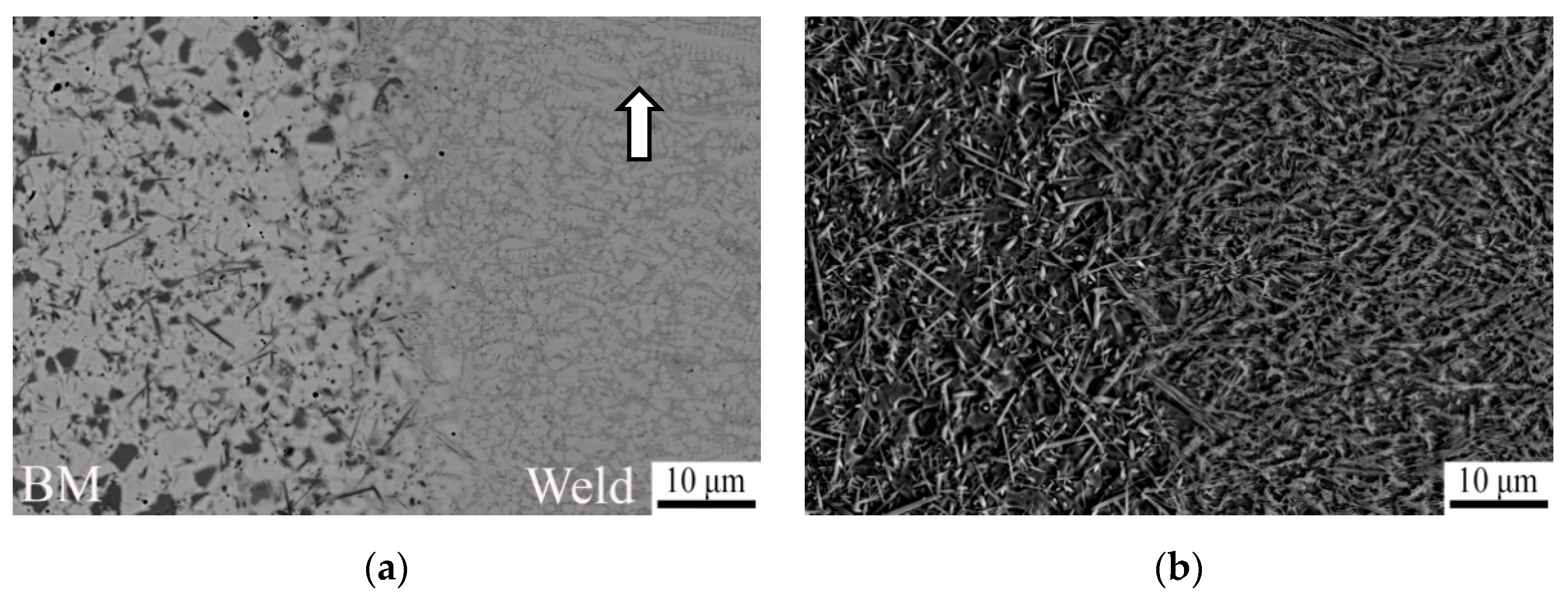
  • The TiB reinforcements in a bcc-Ti matrix had a needle-like shape with the average thickness of 500 ± 300 nm. The average grain size of the bcc Ti matrix was 14 ± 6 μm. Martensitic α″ precipitations with an average thickness of ~200 nm were found in the initial microstructure.
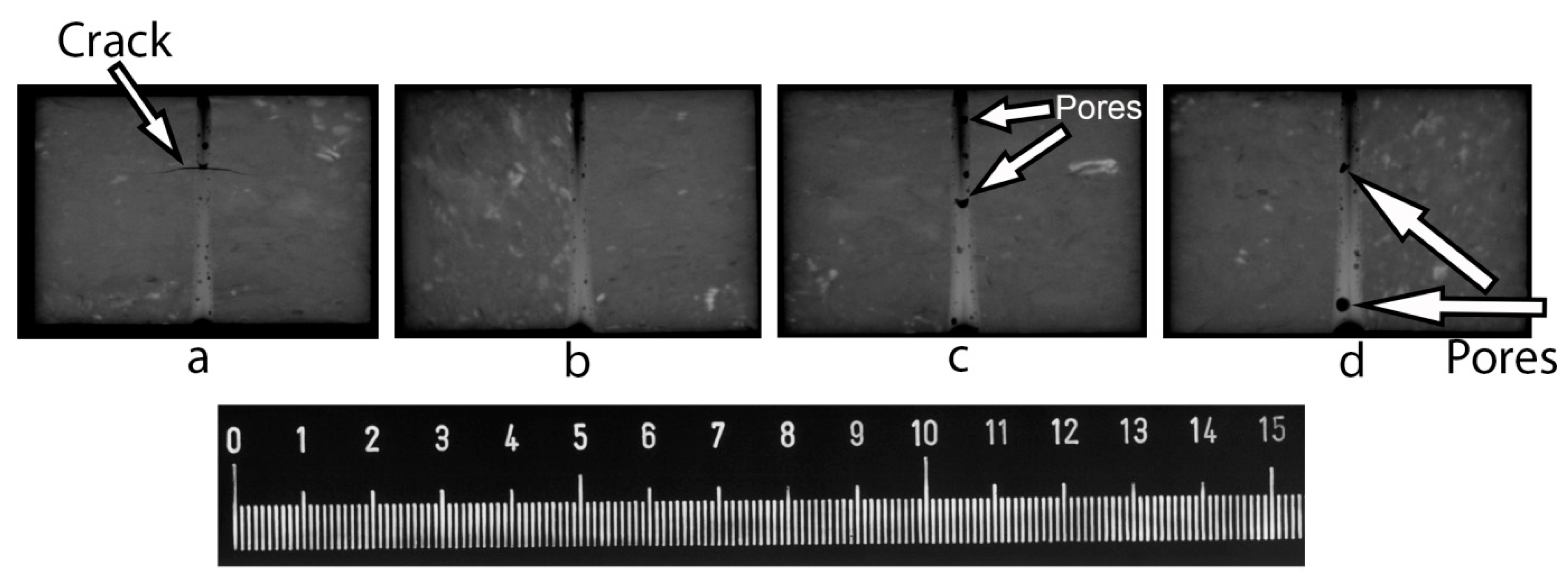
  • All welds obtained at different pre-heating temperatures (without pre-heating and at 200, 400, 600 °C) consisted of pores with the average diameter 30 ± 30 μm; however, some single pores were of 200–300 µm in diameter.
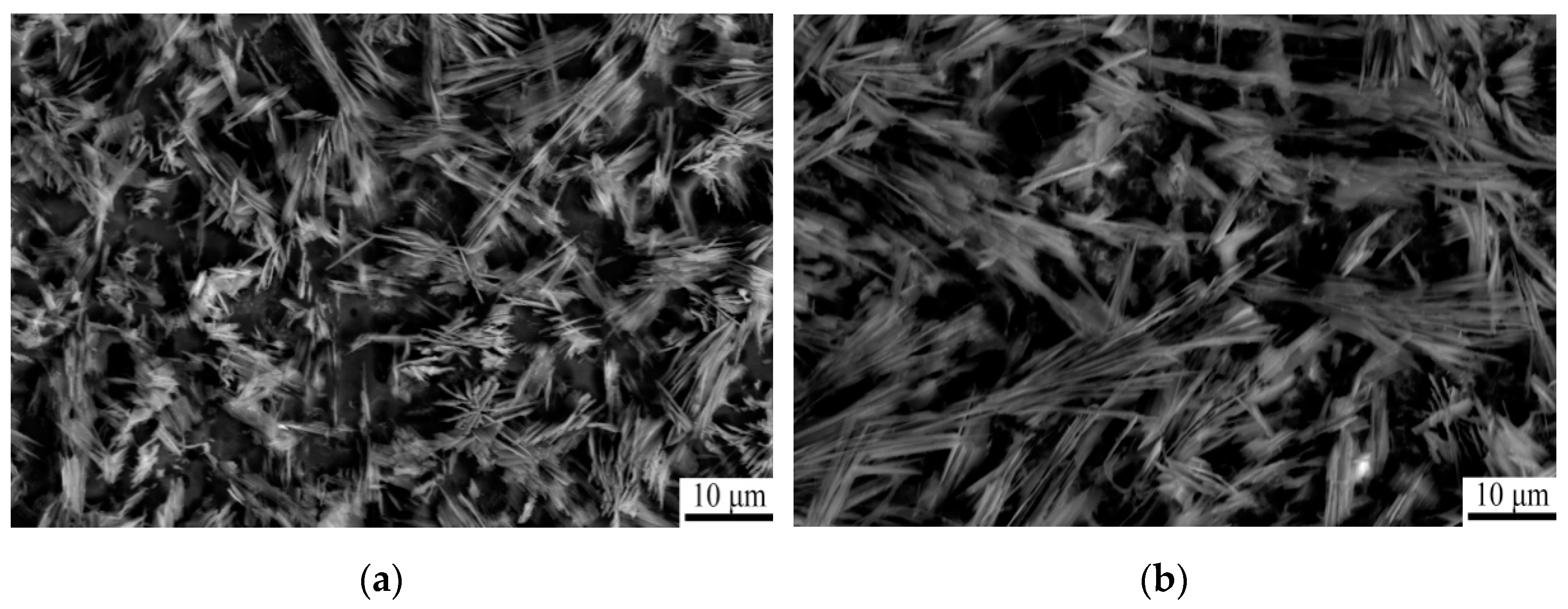
  • Well-defined dendrite structure consisted of Ti-15%Mo, and TiB in the interdendritic spaces was formed. An increase in the aspect ratio of TiB by a factor of 2 contributed to embrittlement of the weld.
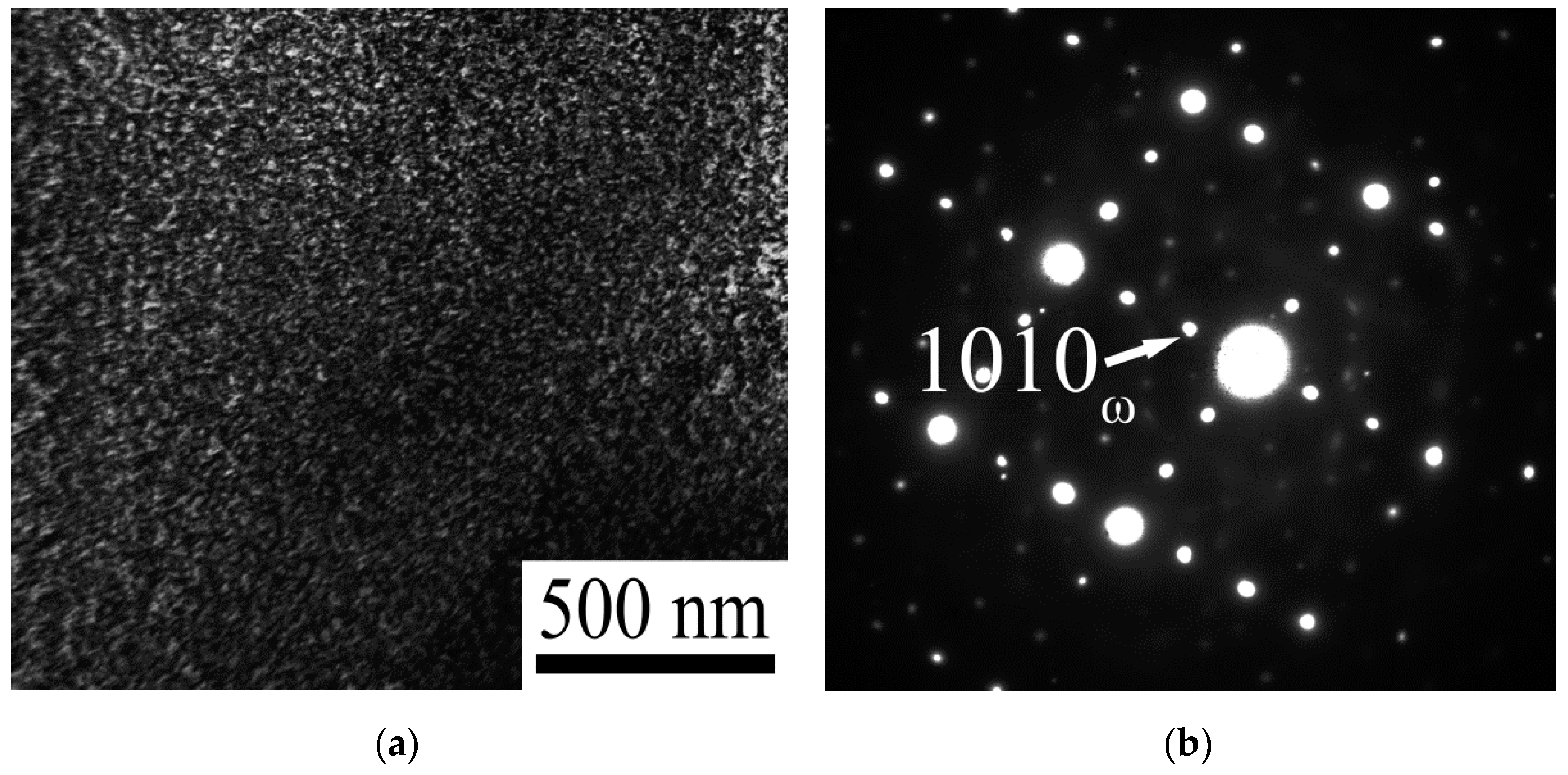
  • Another factor of both strengthening and embrittlement of laser beam welded specimens without pre-heating and at pre-heating temperature 200 °C is the ω phase particles formation. The ω phase measuring ~10 nm in diameter was found in the weld zone of the composite welded without pre-heating.
  • The maximum values of microhardness (700 HV) were found in the fusion zone at room temperature at pre-heating temperature of 200 °C. Microhardness of the state obtained at pre-heating temperature 600 °C does not differ noticeably from the microhardness of the base material (~500 HV).

Author Contributions

Conceptualization, S.Z. and N.K.; methodology, M.O., R.D. and V.V.; validation, S.Z., N.K. and M.O.; formal analysis, S.Z., N.S. and N.K.; investigation, M.O., E.P., R.D. and V.V.; resources, S.Z. and N.K.; data curation, E.P. and M.O.; writing—original draft preparation, M.O.; writing—review and editing, S.Z., N.S. and N.K.; visualization, M.O.; supervision, S.Z. and N.K.; project administration, S.Z. and N.K. All authors have read and agreed to the published version of the manuscript.

Funding

This research was funded by the Russian Science Foundation, Grant Number 19-79-30066.

Institutional Review Board Statement

Not applicable.

Informed Consent Statement

Not applicable.

Data Availability Statement

The data presented in this study are available on request from the corresponding author. The data are not publicly available because it is a part of an ongoing study.

Acknowledgments

The authors gratefully acknowledge the financial support from the Russian Science Foundation (Grant Number 19-79-30066). The authors are grateful to the personnel of the Joint Research Centre, Belgorod State University, for their assistance with the instrumental analysis.

Conflicts of Interest

The authors declare no conflict of interest.

References

  1. Saito, T.; Furuta, T.; Yamaguchi, T. Development of low cost titanium matrix composite. In Advances in Titanium Metal Matrix Composites, the Minerals, Metals and Materials Society; Froes, F.H., Storer, J., Eds.; TMS: Warrendale, PA, USA, 1995; pp. 33–44. [Google Scholar]
  2. Godfrey, T.M.T.; Goodwin, P.S.; Ward-Close, C.M. Titanium Particulate Metal Matrix Composites—Reinforcement, Production Methods, and Mechanical Properties. Adv. Eng. Mater. 2000, 2, 85–91. [Google Scholar] [CrossRef]
  3. Feng, H.; Zhou, Y.; Jia, D.; Meng, Q.; Rao, J. Growth mechanism of in situ TiB whiskers in spark plasma sintered TiB/Ti metal matrix composites. Cryst. Growth Des. 2006, 6, 1626–1630. [Google Scholar] [CrossRef]
  4. Radhakrishna Bhat, B.V.; Subramanyam, J.; Bhanu Prasad, V.V. Preparation of Ti-TiB-TiC & Ti-TiB composites by in-situ reaction hot pressing. Mater. Sci. Eng. A 2002, 325, 126–130. [Google Scholar]
  5. Zherebtsov, S.; Ozerov, M.; Klimova, M.; Stepanov, N.; Vershinina, T.; Ivanisenko, Y.; Salishchev, G. Effect of High-Pressure Torsion on Structure and Properties of Ti-15Mo/TiB Metal-Matrix Composite. Materials 2018, 11, 2426. [Google Scholar] [CrossRef] [Green Version]
  6. Ravi Chandran, K.S.; Panda, K.B.; Sahay, S.S. TiBw-reinforced Ti composites: Processing, properties, application, prospects, and research needs. JOM 2004, 56, 42–48. [Google Scholar] [CrossRef]
  7. Ozerov, M.S.; Klimova, M.V.; Stepanov, N.D.; Zherebtsov, S.V. Microstructure evolution of a Ti/TiB metal-matrix composite during high-temperature deformation. Mater. Phys. Mech. 2018, 38, 54–63. [Google Scholar]
  8. Morsi, K. Review: Titanium–titanium boride composites. J. Mater. Sci. 2019, 54, 6753–6771. [Google Scholar] [CrossRef]
  9. Zherebtsov, S.; Ozerov, M.; Klimova, M.; Moskovskikh, D.; Stepanov, N.; Salishchev, G. Mechanical behavior and microstructure evolution of a Ti-15Mo/TiB titanium matrix composite during hot deformation. Metals 2019, 9, 1175. [Google Scholar] [CrossRef] [Green Version]
  10. Zhang, C.J.; Kong, F.T.; Xu, L.J.; Zhao, E.T.; Xiao, S.L.; Chen, Y.Y.; Deng, N.J.; Ge, W.; Xu, G.J. Temperature dependence of tensile properties and fracture behavior of as rolled TiB/Ti composite sheet. Mater. Sci. Eng. A 2012, 556, 962–969. [Google Scholar] [CrossRef]
  11. Panda, K.B.; Ravi Chandran, K.S. Synthesis of Ductile Titanium–Titanium Boride (Ti-TiB) Composites with a Beta-Titanium Matrix: The Nature of TiB Formation and Composite Properties. Metall. Mater. Trans. A 2003, 34, 1371–1385. [Google Scholar] [CrossRef]
  12. Rielli, V.V.; Amigó-Borrás, V.; Contieri, R.J. Single step heat treatment for the development of beta titanium composites with in-situ TiB and TiC reinforcement. Mater. Charact. 2000, 163, 110286. [Google Scholar] [CrossRef]
  13. Khorasani, A.M.; Goldberg, M.; Doeven, E.H.; Littlefair, G. Titanium in biomedical applications—Properties and fabrication: A review. J. Biomater. Tissue Eng. 2015, 5, 593–619. [Google Scholar] [CrossRef]
  14. Chen, Q.; Thouas, G.A. Metallic implant biomaterials. Mater. Sci. Eng. R Rep. 2015, 87, 1–57. [Google Scholar] [CrossRef]
  15. Boyer, R.R. An overview on the use of titanium in the aerospace industry. Mater. Sci. Eng. A 1996, 213, 103–114. [Google Scholar] [CrossRef]
  16. Boyer, R.R.; Briggs, R.D. The use of β titanium alloys in the aerospace industry. J. Mater. Eng. Perform. 2005, 14, 681–685. [Google Scholar] [CrossRef]
  17. Short, A.B. Gas tungsten arc welding of α + β titanium alloys: A review. Mater. Sci. Technol. 2009, 25, 309–324. [Google Scholar] [CrossRef]
  18. Brewer, W.D.; Bird, R.K.; Wallace, T.A. Titanium alloys and processing for high speed aircraft. Mater. Sci. Eng. A 1998, 243, 299–304. [Google Scholar] [CrossRef] [Green Version]
  19. Bulkov, A.K.; Peshkov, V.V.; Petrenko, V.R.; Balbekov, D.N.; Stryguin, A.I. Effect of technological parameters on the process of diffusion welding of titanium. Weld. Int. 2014, 28, 222–227. [Google Scholar] [CrossRef]
  20. Auwal, S.T.; Ramesh, S.; Yusof, F.; Manladan, S.M. A review on laser beam welding of titanium alloys. Int. J. Adv. Manuf. Technol. 2018, 97, 1071–1098. [Google Scholar] [CrossRef]
  21. Li, Z.; Gobbi, S.L.; Norris, I.; Zolotovsky, S.; Richter, K.H. Laser welding techniques for titanium alloy sheet. J. Mater. Process. Technol. 1997, 65, 203–208. [Google Scholar] [CrossRef]
  22. Kashaev, N.; Ventzke, V.; Fomichev, V.; Fomin, F.; Riekehr, S. Effect of Nd: YAG laser beam welding on weld morphology and mechanical properties of Ti–6Al–4V butt joints and T-joints. Opt. Lasers Eng. 2016, 86, 172–180. [Google Scholar] [CrossRef]
  23. Burkhardt, I.; Ventzke, V.; Riekehr, S.; Kashaev, N.; Enz, J. Laser welding and microstructural characterization of dissimilar -TiAl-Ti6242 joints. Intermetallics 2019, 104, 74–83. [Google Scholar] [CrossRef]
  24. Gialos, A.A.; Zeimpekis, V.; Alexopoulos, N.D.; Kashaev, N.; Riekehr, S.; Karanika, A. Investigating the impact of sustainability in the production of aeronautical subscale components. J. Clean. Prod. 2018, 176, 785–799. [Google Scholar] [CrossRef]
  25. Guo, J.; Gougeon, P.; Chen, X.-G. Study on laser welding of AA1100-16 vol.% B4C metal–matrix composites. Compos. Part B Eng. 2012, 43, 2400–2408. [Google Scholar] [CrossRef]
  26. Bassani, P.; Capello, E.; Colombo, D.; Previtali, B.; Vedani, M. Effect of process parameters on bead properties of A359/SiC MMCs welded by laser. Compos. Part A Appl. Sci. Manuf. 2007, 38, 1089–1098. [Google Scholar] [CrossRef]
  27. Mao, J.W.; Lu, W.J.; Wang, L.Q.; Qin, J.N.; Zhang, D. Microstructures and mechanical properties in laser beam welds of titanium matrix composites. Sci. Technol. Weld. Join. 2014, 19, 142–149. [Google Scholar] [CrossRef]
  28. Hirose, A.; Matsuhiro, Y.; Kotoh, M.; Fukumoto, S.; Kobayashi, K.F. Laser-beam welding of SiC fibre-reinforced Ti-6Al-4V composite. J. Mater. Sci. 1993, 28, 349–355. [Google Scholar] [CrossRef]
  29. Will, G. Powder Diffraction: The Rietveld Method and the Two-Stage Method to Determine and Refine Crystal Structures from Powder Diffraction Data; Springer: Berlin, Germany, 2005. [Google Scholar]
  30. Petrov, G.L.; Khatuntsev, A.N. Role of chemical reactions in the formation of pores in the welding of titanium alloys. Prod. Eng. 1975, 22, 81–84. [Google Scholar]
  31. Cao, X.; Debaecker, G.; Poirier, E.; Marya, S.; Cuddy, J.; Birur, A.; Wanjara, P. Tolerances of joint gaps in Nd:YAG laser welded Ti-6Al-4V alloy with the addition of filler wire. J. Laser Appl. 2011, 23, 012004. [Google Scholar] [CrossRef]
  32. Kabir, A.S.H.; Cao, X.; Gholipour, J.; Wanjara, P.; Cuddy, J.; Birur, A.; Medraj, M. Effect of postweld heat treatment on microstructure, hardness, and tensile properties of laser-welded Ti-6Al-4V. Metall. Mater. Trans. A 2012, 43, 4171–4184. [Google Scholar] [CrossRef] [Green Version]
  33. Fomin, F.; Klusemann, B.; Kashaev, N. Surface modification methods for fatigue properties improvement of laser-beam-welded Ti-6Al-4V butt joints. Procedia Struct. Integr. 2018, 13, 273–278. [Google Scholar] [CrossRef]
  34. Mao, J.; Chen, L.; Wang, L.; Lu, W.; Guo, X. Evoilution behavior of TiB whisker during laser welding in-situ synthesized TiB/Ti composites. In Proceedings of the 20th International Conference on Composite Materials, Copenhagen, Denmark, 19–24 July 2015. [Google Scholar]
  35. Chen, B.; Shen, J.; Ye, X.; Jia, L.; Li, S.; Umeda, J.; Takahashi, M.; Kondoh, K. Length effect of carbon nanotubes on the strengthening mechanisms in metal matrix composites. Acta Mater. 2017, 140, 317–325. [Google Scholar] [CrossRef]
  36. Koo, M.Y.; Park, J.S.; Park, M.K.; Kim, K.T.; Hong, S.H. Effect of aspect ratios of in situ formed TiB whiskers on the mechanical properties of TiBw/Ti-6Al-4V composites. Scr. Mater. 2012, 66, 487–490. [Google Scholar] [CrossRef]
  37. Ozerov, M.; Klimova, M.; Sokolovsky, V.; Stepanov, N.; Popov, A.; Boldin, M.; Zherebtsov, S. Evolution of microstructure and mechanical properties of Ti/TiB metal matrix composite during isothermal multiaxial forging. J. Alloys Compd. 2019, 770, 840–848. [Google Scholar] [CrossRef]
  38. Zherebtsov, S.; Ozerov, M.; Povolyaeva, E.; Sokolovsky, V.; Stepanov, N.; Moskovskikh, D.; Salishchev, G. Effect of hot rolling on the microstructure and mechanical properties of a Ti-15Mo/TiB metal-matrix composite. Metals 2020, 10, 40. [Google Scholar] [CrossRef] [Green Version]
  39. Hickman, B.S. The Formation of Omega Phase in Titanium and Zirconium Alloys: A Review. J. Mater. Sci. 1969, 4, 554–563. [Google Scholar] [CrossRef]
  40. Zwicker, U. Titanium and Titanium Alloys; Springer: Berlin, Germany, 1974. [Google Scholar]
  41. Gatina, S.A.; Semenova, I.P.; Joern, L.; Valiev, R.Z. Nanostructuring and Phase Transformations in the β-alloy Ti-15Mo during High-Pressure Torsion. Adv. Eng. Mater. 2015, 17, 1742–1747. [Google Scholar] [CrossRef]
Figure 1. Microstructure of Ti-15%Mo/TiB composite in the initial condition: (a) SEM image of unetched surface; (b) SEM image of etched surface; (c)—XRD pattern; (d,e) TEM bright field images; (f) TEM bright field image and a diffraction pattern (inserted) obtained from the α’’ phase.
Metals 11 00506 g001aMetals 11 00506 g001b
Figure 2. Macrostructure of cross section Ti-15%Mo/TiB composite after LBW at different preheating temperatures: (a) without pre-heating; (b) 200 °C; (c) 400 °C; or (d) 600 °C.
Metals 11 00506 g002
Figure 3. Radiographs images of the general view of welded samples obtained at different pre-heating temperatures: without pre-heating (a); 200 °C (b); 400 °C (c); or 600 °C (d).
Metals 11 00506 g003
Figure 4. SEM images of the Ti-15%Mo/TiB composite microstructure at the border between the welds and base material (BM) obtained at room temperature (without pre-heating) (a,b) or at 600 °C (c,d); (a,c) unetched and (b,d) etched surfaces.
Metals 11 00506 g004aMetals 11 00506 g004b
Figure 5. SEM images of the Ti-15%Mo/TiB composite microstructure in the weld area after etching: (a) room temperature (without pre-heating), (b) 600 °C.
Metals 11 00506 g005
Figure 6. Average diameter of individual TiB whiskers (a) and apparent width of TiB dendrites (b) in the weld zone as a function of pre-heating temperature.
Metals 11 00506 g006
Figure 7. Microhardness profiles across the weld obtained (a) without pre-heating; the microhardness was measured along radiation exposure side (black line), half-thickness (red line), and weld root side (blue line); (b) at different pre-heating temperature; the microhardness was measured at the midthickness.
Metals 11 00506 g007
Figure 8. TEM bright field image (a) and selected area diffraction pattern (b) of the specimen welded at room temperature.
Metals 11 00506 g008
Publisher’s Note: MDPI stays neutral with regard to jurisdictional claims in published maps and institutional affiliations.

