Article

Effects of Heat Treatments on Microstructures and Mechanical Properties of Ti6Al4V Alloy Produced by Laser Solid Forming

1
School of Mechanical Engineering and Automation, Beihang University, Beijing 100191, China
2
Chengdu Aircraft Industrial Refco Group Ltd., Chengdu 610073, China
3
School of Materials Science and Engineering, Jilin University, 5988 Renmin Street, Changchun 130025, China
4
State Key Laboratory of Tribology, Department of Mechanical Engineering, Tsinghua University, Beijing 100084, China
*
Authors to whom correspondence should be addressed.
Metals 2021, 11(2), 346; https://doi.org/10.3390/met11020346
Submission received: 3 February 2021 / Revised: 10 February 2021 / Accepted: 11 February 2021 / Published: 19 February 2021

Abstract

:
The steep thermal gradient and complicated thermal cycle occur in the fabrication of Ti6Al4V alloy during laser solid forming (LSF). That leads to obvious anisotropic mechanical properties and requires essential heat treatments to improve its performance. In this work, different heat treatment strategies under vacuum condition were used to study the evolution of microstructures and mechanical properties of Ti6Al4V alloy produced by LSF. The results show that transformation from α phase into lamellar α + β dual-phases structure is introduced at low temperature (550 °C), and the α phase is broken and refined at higher temperature (800 °C). Tensile tests present the increase of elongations in the horizontal and vertical directions by 12.4% and 13.2% for specimens treated by two-step heat treatment (750 °C × 4 h + 500 °C × 1 h). Fatigue crack growth (FCG) lives of LSFed Ti6Al4V alloy after different heat treatments were improved due to the elimination of residual tensile stress and the transformation of α phase into α + β dual-phase structure. Specimens treated at 800 °C for 4 h exhibit a higher fatigue life among those heat-treated alloys. The low sensitivities of the FCG behavior in the Paris-zone to different heat treatments under vacuum condition are explored in the FCG testing of Ti6Al4V alloy.

1. Introduction

Laser solid forming (LSF, the abbreviations are summarized in Table 1) is a direct additive manufacturing (AM) technology, in which metallic powders are gradually melted under a high-power laser irradiation, and re-solidified to form parts with complex geometries, such as aircraft wings with integral rib reinforcement structures, as demonstrated by Zhao et al. [1]. LSF possesses significant advantages over conventional manufacturing, such as non-contact processing, net shape production, and free design in many cases including those by Zhang et al. [2] and Paydas et al. [3]. Thijs et al. [4] reported that various metallic materials have been manufactured using LSF. As for additive manufacturing of complex parts with high mechanical demands, LSF behaves in the non-limited forming size, composite or gradient structure fabrication upon the same basic parts, and in situ repair of damaged parts. Additionally, LSF can be easily combined with the traditional processing technology, such as forging and casting, giving full play to the advantages of various processing technology [5,6,7].
Ti6Al4V alloy was reported with high specific strength, good ductility, and excellent fatigue properties by Liu et al. [8]. Ti6Al4V alloy has received prime attention owing to its broad applications in aerospace, biomedical, and other fields [9]. The mechanical properties of the LSF-fabricated Ti6Al4V alloy depend largely on their microstructure and constituent phases [10]. As for Ti6Al4V alloy, it is often recognized that the ultimate microstructure is dominated by α′ martensite as a result of rapid cooling. The elongated prior-β grain boundaries in conjunction with the presence of acicular α′ martensite favor intergranular failure. Thus, the post-heat treatment is needed to transform the α′ martensite into α and β to imparts high yield strength and ductility to the as-deposited Ti6Al4V alloy without heat treatment. For additively manufactured Ti6Al4V alloy, Xu et al. [11] observed the unacceptable α’ phase martensite in the pre-deposited β columnar crystals, which results in low elongation and poor toughness. In addition, Yan and Yu [12] reported that the elongation of the Ti6Al4V alloy produced by AM was less than 5%, which was below the minimum threshold suggested for critical structural applications. It is essential to post-process AM-fabricated Ti6Al4V alloy to obtain proper microstructure and phases for practical application. According to Vilaro et al. [13], heat treatment technology has become an effective approach to improve the performance of AM-fabricated Ti6Al4V alloy. Ter Haar and Becker [14] found that the α’ phase martensite were formed in four different sizes due to the rapid cooling after AM, and they were sequentially dissolved from small to large in size with the increasing heat treatment temperatures. The decomposition of the unacceptable α’ phase martensite was introduced to maintain the strength and ductility of Ti6Al4V alloy. In addition, when the anneal temperature was lower than β-transus-temperature, the original α’ phase martensitic was easily transformed into a lamellar α + β dual-phase structure as demonstrated by Vrancken et al. [15]. Kumar and Ramamurty [16] reported that the fatigue resistance of Ti6Al4V alloy after heat treatment with a basket-like α + β structure can be improved significantly due to the appropriate lamellar thickness and colony size. On the other hand, heat treatment is often applied to modify internal stress for fatigue crack growth (FCG) behavior improvement [17]. Wycisk et al. [18] show that the stress intensity threshold factor (ΔKth) is not sensitive to the size of prefabricated crack defects due to the fine microstructure. Irving and Beevers [19] found that crack deflection occurred along the α-phase boundary, and as the value of stress intensity factor (ΔK) increased, the crack propagated along the colony boundary. In the post-crack stage, when removing the residual stress of the parts produced by AM, a similar FCG behavior is found in the parts produced by traditional manufacturing processes as reported by Leuders et al. [20]. From the above, heat treatment plays a significant role in the improvement of mechanical properties of the AM-fabricated Ti6Al4V alloy, and the important mechanistic details have remained elusive. It is necessary to study the information about the evolution of microstructures and mechanical properties of LSF-fabricated Ti6Al4V Alloy after heat treatment under vacuum condition. This may provide new insights for the understanding of the effect of post-AM heat treatment.
In this study, different heat treatments under vacuum condition were used to investigate the microstructure evolution of LSF-fabricated Ti6Al4V alloy. The mechanical properties and FCG tests were performed on specimens with different orientations to evaluate the effect of heat treatments on the anisotropy of LSF-fabricated Ti6Al4V alloy. Further discussion was conducted to reveal the influence mechanism of heat treatments on microstructure and mechanical properties.

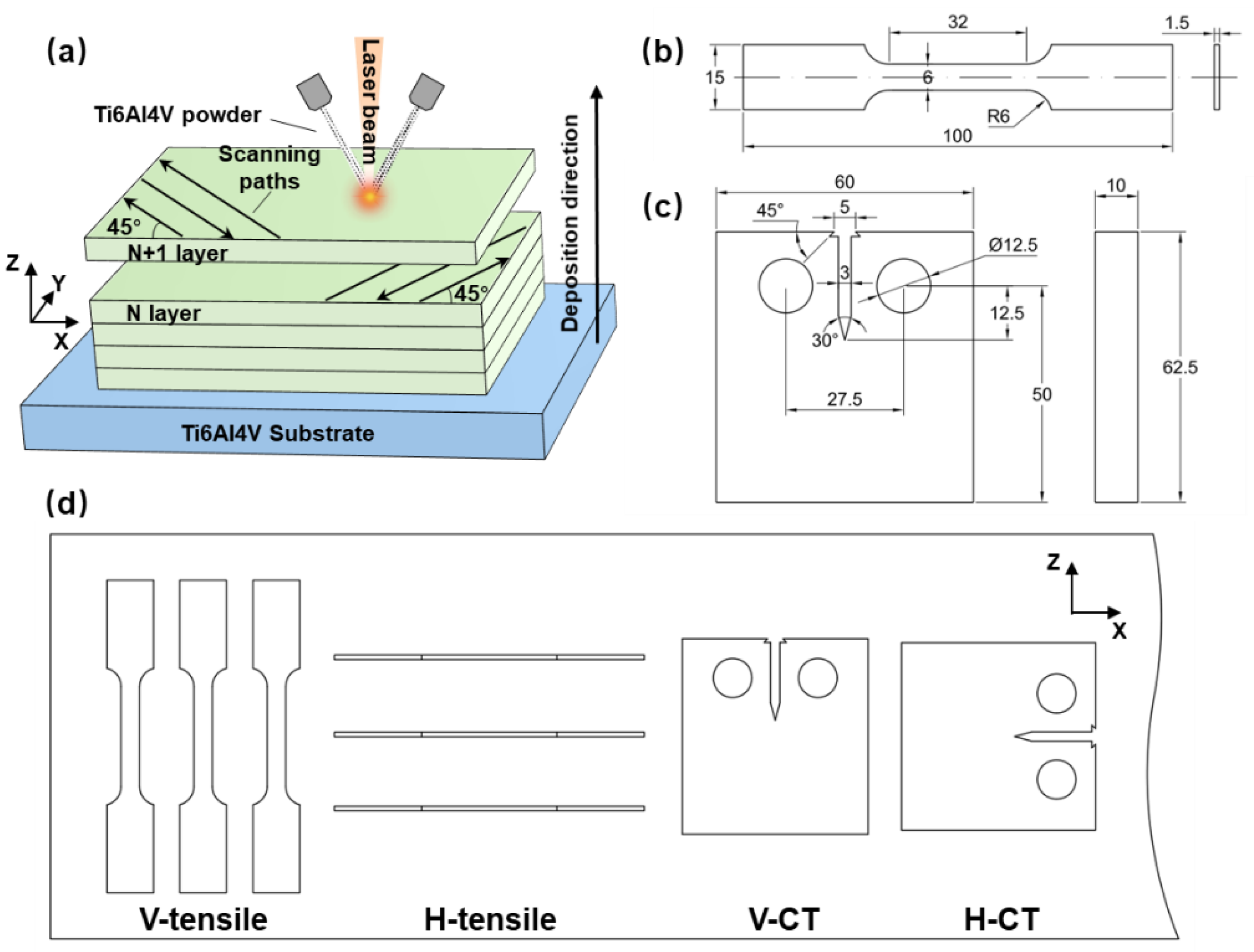
2. Materials and Methods

2.1. Materials

Ti6Al4V alloy powder (provided by Xi’an Bright Laser Technology Co., Ltd., Xi’an, China) was prepared by gas atomization method and then dried in a vacuum brazing furnace (VBF-113) at 120 ± 5 °C for 2 h to remove the absorbed water. The average chemical composition (wt.%) of Ti6Al4V alloy powder was measured as Al: 6.75, V: 4.5, O: 0.20, H: 0.015, N: 0.05, C: 0.10, Fe: 0.30, and Ti: balance. The LSF of Ti6Al4V alloy powder was conducted in the Metal AM Machine (BLT-C600, Xi’an Bright Laser Technology Co., Ltd., Xi’an, China). In LSF, laser processing parameters directly affect the microstructure and mechanical properties due to the fast melting and re-solidifying procedure. Obvious LSF defects, such as pores and cracks, were formed during LSF when inappropriate laser processing parameters were adopted. In a view of manufacturing efficiency, beam diameter, laser power, and scanning velocity have significant effects on the width of cladding layer. Scanning velocity and powder feed rate determine the height of cladding layer. Thus, based on the pre-study of laser processing parameters, the following parameters were adopted in this study: A laser power of 3 kW, a beam diameter of 5 mm, a scanning velocity of 720–900 mm/min, and a powder feed rate of 25–50 g/min. As shown in Figure 1a, a 45° cross-directional laser scanning strategy was used to reduce the anisotropy of mechanical properties during LSF.

2.2. Heat Treatment

In this study, different treatment under vacuum condition were conducted to study the effect of heat treatments on the microstructures and mechanical properties of LSFed Ti6Al4V alloy. Table 2 lists the specific parameters of the three heat treatments, labeled HT1, HT2, and HT3, respectively. As shown in Table 2, single-step annealing was used for HT1 and HT2, and two-step process was used for HT3. Those heat treatments were adopted considering the stress-relieving anneal temperature, where the maximum temperatures are lower than the β-transition temperature. HT1 and HT2 were conducted in the low temperature region and medium temperature region, respectively. In HT3, the first-step annealing was conducted in the medium temperature region, and the second-step process was performed in the low temperature region. A Vacuum Brazing (VBF-113) Furnace was used for different heat treatment processing, with the degree of vacuum controlled below 5 × 10⁻³ Pa. The proposed single or two-step processes under vacuum conditions ensure the reduction of oxidation and hydrogen removal, and reduce residual stress in LSFed Ti6Al4V alloy. The heating rate was kept constant at 10 °C/min, and furnace cooling (FC) was adopted to drop to room temperature. FC was adopted under the consideration that the aforementioned different treatments were conducted in the vacuum furnace with the degree of vacuum controlled below 5 × 10⁻³ Pa, and sequent quenching without FC would lead to the oxidation of sensors in the furnace. Additionally, LSFed Ti6Al4V alloy cooled by quenching is prone to martensite phase, resulting in a decrease in elongation properties.

2.3. Microstructure and Mechanical Property Measurements

Metallographic specimens were cut from as-deposited and heat-treated Ti6Al4V alloy by EDM, and then ground, polished, and etched with Keller reagent (HF: HNO3: H2O = 1:3:7). The microstructure was observed using an optical microscope (OM, OLYMPUS DP72, Olympus Corp., Tokyo, Japan) and scanning electron microscope (SEM, JEOL 7001, JEOL Ltd., Tokyo, Japan).
Vickers microhardness was measured on the etched specimens using a FM-800 microhardness tester, with a load of 300 g and a dwell time of 15 s. Four blocks with a size of 10 × 10 × 10 mm3 were prepared from the same height of the LSFed Ti6Al4V wall, and three of them were heat-treated. For those blocks, 15 measuring points were conducted with an equal interval of 0.5 mm, and the indentations were randomly distributed on the grain boundary or in the grain. Specimens for tensile test were prepared in accordance with the ASTM: E8/E8M standard [21], and the size characteristics were shown in Figure 1b. In order to study the anisotropy of Ti6Al4V alloy, tensile specimens in horizontal (H) and vertical (V) directions were prepared, as shown in Figure 1d. Tensile tests were carried out by a computerized tensile tester (Instron-8801, Instron Corp., Norwood, MA, USA) with a velocity of 1.5 mm/min and a restricted maximum tensile force of 10 kN at room temperature. As shown in Figure 1c, FCG rate experiments were carried out using compact tensile (CT) specimens (W = 50 mm, B = 10 mm) in accordance with ASTM: E647 standard [22]. As shown in Figure 1d, CT specimens were also produced with horizontal and vertical direction ones as the crack growth plane perpendicular and parallel to the deposition direction, respectively. Prior to commencing the FCG rate evaluation, a 1 mm long pre-crack was developed at the notch root with a constant external load of 7 kN. The actual FCG rate experiments were performed with a pull-pull load (R) of 0.1, a constant amplitude (ΔP) of 6 kN, and a frequency of 20 Hz at room temperature on Instron-8801. The length of the fatigue crack was measured by a crack opening displacement (COD) gauge attached to the specimen.

3. Results

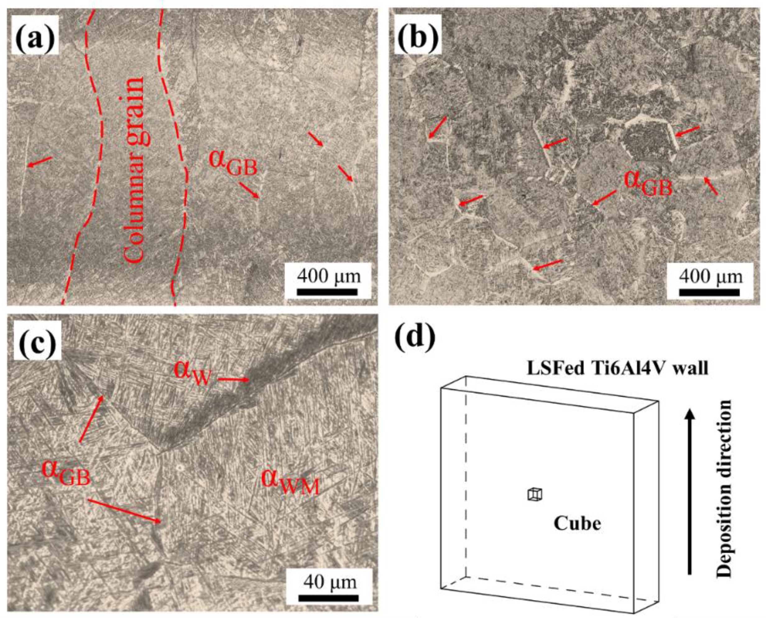
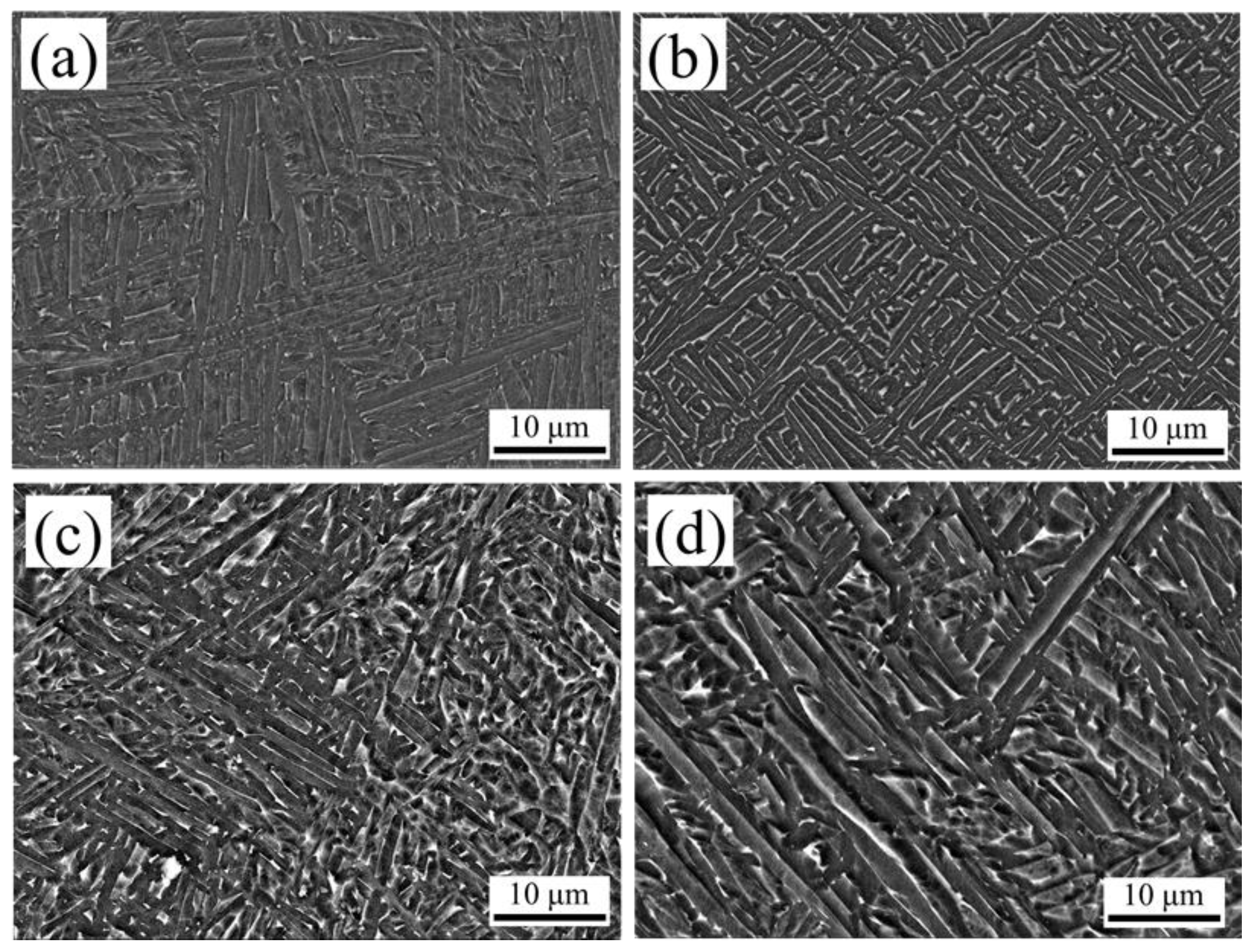
3.1. The Microstructures of LSFed Ti6Al4V Alloy before and after Heat Treatment

Figure 2a,b shows the typical microstructure of the as-deposited Ti6Al4V alloy along vertical and horizontal directions. The observed cube was schematic illustrated in Figure 2d. As shown in Figure 2a, columnar β crystals grew across several deposition layers along the vertical direction with a width of approximately 300~500 μm. Tan et al. [23] attributed this to the large positive temperature gradient existing in the solid-liquid interface in the molten pool. As shown in Figure 2b, a checkerboard shape microstructure appeared in the horizontal direction, which represents the cross section of columnar β crystals. In addition, different types of α phases were formed owing to the complicated thermal cycle and rapid cooling rate during the LSF process as demonstrated by Fu et al. [24]. According to the distribution characteristics of α phases reported by Zhao et al. [1], it can be divided into the α phases in grain boundary (αGB), the Widmanstätten structure with parallel α plates (αW), and the intragranular basket-weave microstructure (αWM). As shown in Figure 2c, continuous αGB was distributed along the columnar β crystals with a width of 3 μm. αW phases nucleated on the αGB and extended into the columnar β crystals. There is a competitive growth mechanism between αW and αWM in the cooling process during AM. It can be explained that higher undercooling promotes the nucleation and growth of a large number of αWM phases, which hinders the extension of αW from the columnar β crystals boundary to the intragranular, resulting in a dominant basket-weave microstructure.
Figure 3a–d gives representative secondary electron micrographs of the intragranular basket-weave structure for the as-deposited and heat-treated LSF Ti6Al4V specimens. The dark phase is the α phase, and lighter zones are β phase. Table 3 lists the volume fraction of β phase and the width range of α phase. Image J software (v.1.52; National Institutes of Health, Bethesda, MD, USA) was used to convert the SEM image into a binary image, and then use the area analysis method to calculate the percentage of phases. In the as-deposited Ti6Al4V alloy, the α phase width was measured in a large range (between 0.2 μm and 1.8 μm), and this hierarchical microstructure was also observed in the SLM-fabricated Ti6Al4V alloy produced by Yang et al. [25]. For specimens after HT1 in Figure 3b, the α phases were transformed into lamellar α + β dual-phase structure, and the volume fraction of columnar β crystals increased from < 2% to 19%, while the basket-weave microstructure was completely retained. For specimens after HT2 in Figure 3c, a large number of small-sized α phase was broken significantly, with the refinement of large-sized α phases as the maximum size reduced to 0.9 μm in Table 3. Ter Haar and Becker [14] confirmed that small-sized α phases preferentially fragmented and dissolved under moderate temperature treatment. As shown in Figure 3d, since the first-step annealing (750 °C, 4 h) of HT3 was close to that of HT2, the small-sized α phases were broken, and then grown into short-rod or spherical shape in the following low-temperature treatment (500 °C, 1 h). It is also observed that the maximum size of the coarsened α phases was twice that of the microstructure after HT2. In addition, all heat treatments effectively transform the as-deposited α phase into an α + β dual-phase structure. According to Tan et al. [26], this can be explained that the alloying element V was excluded from the transformation process of supersaturated α phases into steady-state α phases, so that V with high concentration promotes the nucleation of columnar β crystals and the growth along the α boundary.

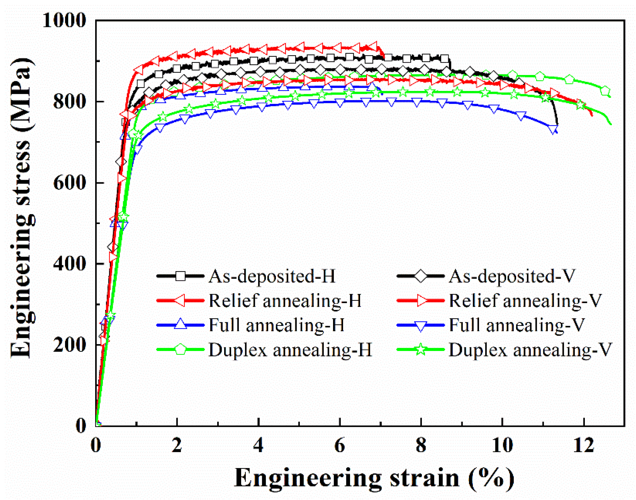
3.2. Mechanical Properties

3.2.1. Microhardness and Tensile Behavior

The microhardness of the as-deposited and heat-treated LSF Ti6Al4V alloy is shown in Table 4. For as-deposited or heat-treated samples, similar microhardness was noted for H and V specimens. The isotropic feature of microhardness indicated that the main basket-weave microstructure within the prior columnar β crystals had no obvious effects on the microhardness in horizontal and vertical directions. As shown in Table 4, the as-deposited specimens exhibited a maximum microhardness of ~370 HV due to the brittle hard α phases formed in the molten pool during rapid cooling. The microhardness of the specimens after the heat treatments was slightly reduced due to the transformation of the α phases into α + β dual-phase structure. Among the heat treatments, the microhardness of the HT1 specimens reached ~355 HV due to the harder β phase accounting for 19%, while the decrease of the β phase content in the HT2 and HT3 material resulted in a lower hardness of ~350 HV.
The curves engineering stress against engineering strain of the as-deposited and heat-treated specimens are shown in Figure 4. The corresponding yield strength (YS), ultimate tensile strength (UTS), and elongation in horizontal and vertical directions are summarized in Table 4. Compared with the tensile properties in horizontal direction, YS and UTS were general lower and elongation was higher in vertical direction for as-deposited and heat-treated Ti6Al4V alloy. The anisotropic mechanical properties were attributed to the orientations of the prior columnar β crystals and the load axis. During the uniaxial stretching process of vertical specimens, the parallel between long axis of the prior columnar β crystals and the tensile axis resulted in a weakened resistance against deformation.
Compared with as-deposited specimens, YS and UTS of specimens treated by HT1 increased by ~35 MPa and ~25 MPa in a horizontal direction and remained basically flat in vertical direction. The results of YS and UTS decreased together both in horizontal and vertical direction for specimens treated by HT2 and HT3. A continuous β phase with a high-volume fraction was formed at the boundary of α phase at low treating temperature (550 °C) in HT1 specimens. The microstructural changes of HT1 specimens blocked the transfer of dislocations between adjacent α phases, resulting in an increase in strength eventually. The tensile strength of titanium alloys mainly depends on the effective slip length. In the basket-weave structure, the effective slip length is equal to the width of the lamellar α phase [3]. The dislocation slips in the α phase and stops at the α/β boundary. As for specimens treated by HT2 and HT3, the volume fractions of columnar β crystals reduced to 8% and 6%, receptively, resulting in the reduction of ability to hinder the dislocation transfer. Along the vertical direction, the elongation of HT1 specimens was similar to that of as-deposited alloy, and the elongations were slightly improved for specimens treated by HT2 and HT3, reaching 12.7% and 13.2%, respectively. The microstructural changes of specimens treated by different heat treatments appeared to have no obvious relations with the low and irregular elongations in horizontal direction. The elongation for HT2 specimens showed an obvious reduction with 8.2% in horizontal direction. That may be attributed to the defects such as holes, which were easy to form stress concentration and acted as the source of fracture.

3.2.2. FCG Tests

The crack length (a) vs. cycles (N) curves (a-N curves) of the as-deposited and heat-treated specimens are shown in Figure 5a,b, corresponding to the crack growth in the horizontal and vertical directions, respectively. This difference of total number of cycles in different directions is confirmed by the bar chart in Figure 5c. As shown in Figure 5a, the as-deposited specimens had similar FCG rate in horizontal direction compared with the heat-treated specimens before the initial 3 × 10⁴ cycles. An obvious difference was presented in Figure 5b where the HT1 and HT2 specimens had lower FCG rates in vertical direction. After 3 × 10⁴ cycles, compared with FCG behaviors in horizontal direction in Figure 5a, the FCG rates of HT1 and HT2 specimens is lower for FCG testing in the vertical direction. As shown in Figure 5c, Fatigue crack growth (FCG) lives of LSFed Ti6Al4V alloy after different heat treatments were improved due to the elimination of residual tensile stress and the transformation of α phase into α + β dual-phase structure as reported by Galarraga et al. [27]. Specimens treated at 800 °C for 4 h exhibits a higher fatigue life among those heat-treated alloys. The as-deposited Ti6Al4V alloy exhibited an isotropic feature of FCG lives, which were confirmed by the similar cycle life in two directions. As for specimens treated by HT1 and HT2, the numbers of cycles in vertical direction were 6~7% longer than that in horizontal direction. That was attributed to the correlation between the crack orientation and the growth direction of the prior columnar β crystals. Ti6Al4V alloy after HT3 condition exhibited the opposite FCG behavior in vertical direction. The number of cycles was approximately 8.5 × 10⁴ and slightly higher than that of as-deposited specimens. The coarsening of α phase with the second-step annealing might have led to the abnormal FCG behaviors for HT3 specimens.
Results of FCG rate (da/dN) with the changes of ΔK in FCG testing for as-deposited and heat-treated Ti6Al4V alloys are displayed in Figure 6. The steady-state extension area was fitted by the Paris formula (da/dN = C·ΔKm, where m is reflected by the slope of the fitted line and lgC corresponds to the intercept on a log-log plot) with ΔK ranging from 22 to 45 MPa·m1/2. The fitted values of m and C were summarized in Table 5 for the as-deposited and heat-treated specimens in different directions. As presented in Table 5, m ranged from 2.34 to 2.74, which was lower than that reported by Kumar et al. [28] in an earlier study for Ti6Al4V alloy produced by SLM. Comparing the m values in horizonal and vertical directions, specimens shared approximately steady-state FCG behavior for as-deposited and heat-treated specimens. Edwards et al. [29] and Edwards and Ramulu [30] found this isotropic feature of FCG rate was also observed in Ti6Al4V specimens produced by SLM and electron beam additive manufacturing (EBAM) as well. The microstructural changes induced by different heat treatments can hardly affect the FCG behavior in the steady-state extension area of Ti6Al4V alloy. Besides the as-deposited specimens, specimens treated by HT1 and HT2 also behaved well in vertical direction with slightly lower m. As for HT3 specimens, opposite FCG behavior was presented, which was proved in Figure 5.

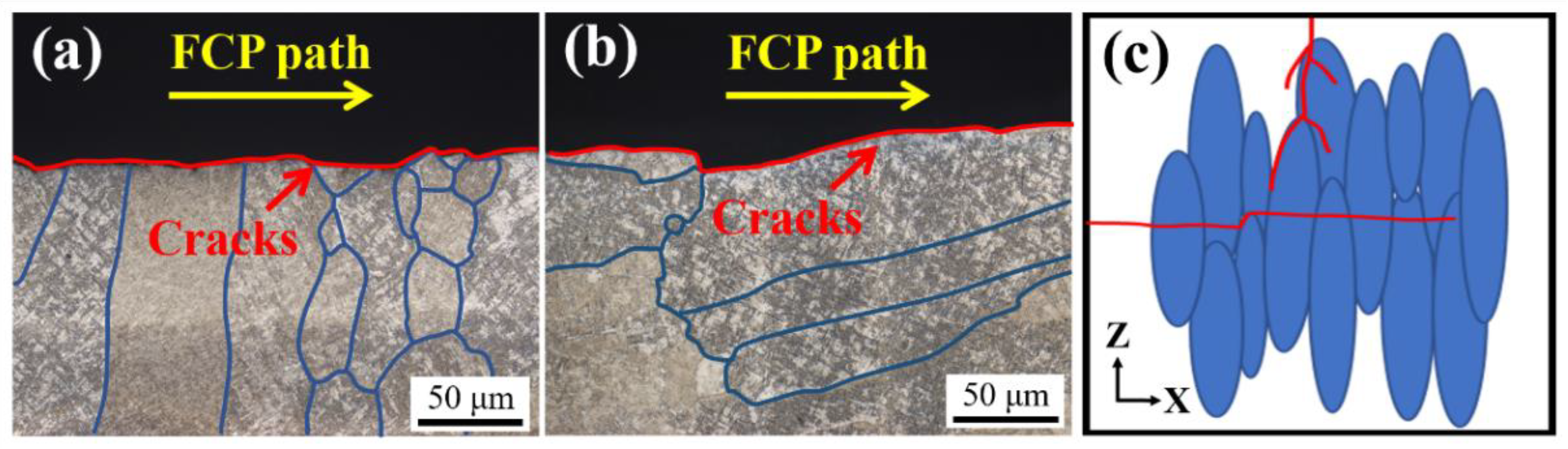
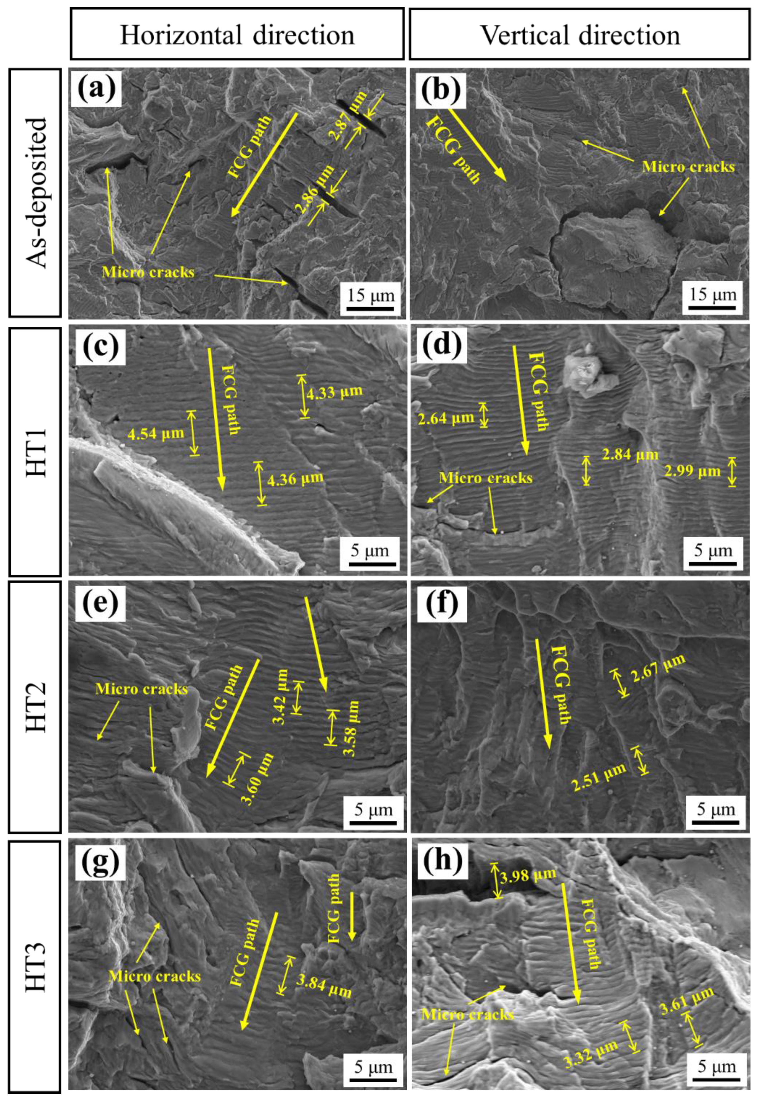
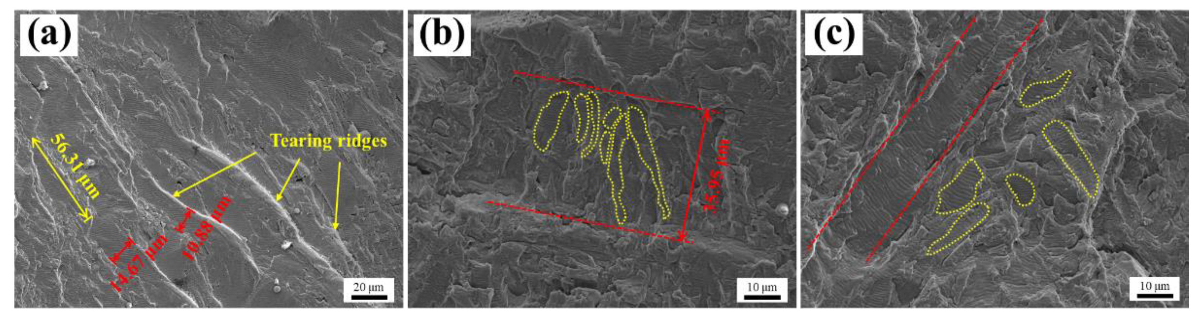
3.2.3. FCG Fracture Morphology

The side morphologies of the FCG fracture for HT1 specimens with lamellar α + β dual-phase structure was shown in Figure 7. In Figure 7a, the smooth fracture was characterized by transgranular cracks, which passed through the prior columnar β crystals. While as shown in Figure 7b, intergranular cracks propagated and extended along the columnar β crystals boundaries for specimens in vertical direction. In FCG testing, the αGB provided an potential path for crack growth due to the strain localization within it reported by Rans et al. [31]. Whether transgranular or intergranular cracks dominate, the generation of fracture depended on the distance the crack front needed to span. The schematic diagram of cracks propagation in horizontal or vertical directions is shown in Figure 7c. In Figure 7c, the cracks are shown with red lines and the prior columnar β crystals are presented with blue ellipses. As presented in Figure 7a,c, the horizontal crack is perpendicular to the prior columnar β crystals. The crack tip cannot get through the long axis of the prior columnar β crystals under external cyclic load, resulting in a transgranular fracture. As the crack tip extends exactly near the head or tail of the columnar β crystals, the slight deflection occurs to present an intergranular crack. In the vertical direction, as shown in Figure 7b,c, the long axis of most prior columnar β crystals is parallel to the generation direction of FCG Fracture. Therefore, the probability increases as the crack propagates along the grain boundary of the columnar β crystals, and intergranular cracks are observed.
The fracture morphologies of the as-deposited and the heat-treated LSF Ti6Al4V alloys in horizontal and vertical direction at a ≈28 mm are shown in Figure 8. For the as-deposited specimens in Figure 8a, the brittle crack propagation was characterized by irregular small facets and a large number of microcracks with a width of ~2.8 μm, indicating that the crack growth occurred in an unstable state. As shown in Figure 8b, the phenomenon that the structure was separated from the matrix was observed for as-deposited sample in the vertical direction, which may be because the coordinated deformation ability of the α colony was poor under the action of alternating stress. As shown in Figure 8c,d, the widths of uniform fatigue striations were observed as 0.88 μm and 0.56 μm, respectively, based on the average widths of five adjacent ductile fatigue striations. That showed the fractures of HT1 specimens was in the stable expansion stage, and the FCG rate in the vertical direction is lower than in the horizontal direction. In the HT2 specimens, the width of fatigue striations was 0.71 μm in the horizontal direction (Figure 8e) and 0.52 μm in the vertical direction (Figure 8f), which indicated that the FCG rate in both directions after HT2 treatment was reduced compared with the HT1 materials, respectively. Compared with the fatigue striations characteristics in Figure 8g, more microcracks with a maximum width of 3.98 μm were observed in the fracture morphologies of HT3 specimens in the vertical direction (Figure 8h). At the same time, the fatigue striations seemed to be generated unevenly along the propagation of fractures. That was consistent with the result that the fatigue life of HT3 specimens was lower than that of specimens treated by HT1 and HT2 in vertical direction.
The specific distribution of fatigue striations in the heat-treated specimens are presented in Figure 9. Figure 9a,c shows horizontal cracks of HT1 and HT3, respectively, and Figure 9b shows vertical cracks of HT2. In Figure 9a, the distance between the parallel tearing ridges was approximately 10–15 μm for specimens in vertical direction treated by HT1. The size of the distance between the parallel tearing ridges was similar to the distance between the large-size α phases shown in Figure 3b. As presented in Figure 9b, the fracture morphologies of specimens treated by HT2 in horizontal direction, and the fatigue striations were transmitted in the small-sized α phases with similar orientations. Those behaviors were stopped at the continuous β phases, which was distributed on the large-size α phases boundary. It was proved by Schroeder et al. [32] that the crack propagation path was deflected at the harder β phases in the α + β dual-phase structure. In addition, the fragmentation of α phases at higher temperature made the continuity of fatigue striations of HT2 specimens worse than that of specimens treated by HT1. For HT3 specimens, the orientation of fatigue striations in Figure 9c became more chaotic due to the fragmentation and coarsening of α phases. Only in the large-size α phases can continuous fatigue striations still be observed. It can be concluded that the distribution of fatigue striations was affected by α size and continuous β phases.

4. Conclusions

In summary, we investigated the microstructures and mechanical properties of Ti6Al4V alloy produced by LSF after different heat treatments (HT1, HT2, and HT3) under vacuum condition. Compared with the coarse β columnar crystals and three types of α phases (αGB, αW, and αWM) in LSFed Ti6Al4V alloy, α + β dual-phase structure were introduced with different formation process after heat treatments under vacuum condition. Several conclusions were conducted as following:
  • HT1 promotes the transformation of α phases into α + β lamellar structure, while the fragmentation of α phases was facilitated in HT2 and HT3 due to higher temperature. The coarsening of α phase was more obvious during HT3 with low-temperature aging process.
  • The microhardness of the heat-treated specimens under vacuum condition were reduced and that of the specimen after HT1 was higher due to the increase in the volume fraction of β phase. The strength of the HT1 specimen was improved as continuous β phase hinders the dislocation transfer between α phases.
  • Tensile tests present the increase of elongations in the horizontal and vertical directions by 12.4% and 13.2% for specimens treated by two-step heat treatment (750 °C × 4 h + 500 °C × 1 h). Fatigue crack growth (FCG) testing shows specimens treated at 800 °C for 4 h exhibits a high fatigue life due to the refined a + β dual-phase structures.
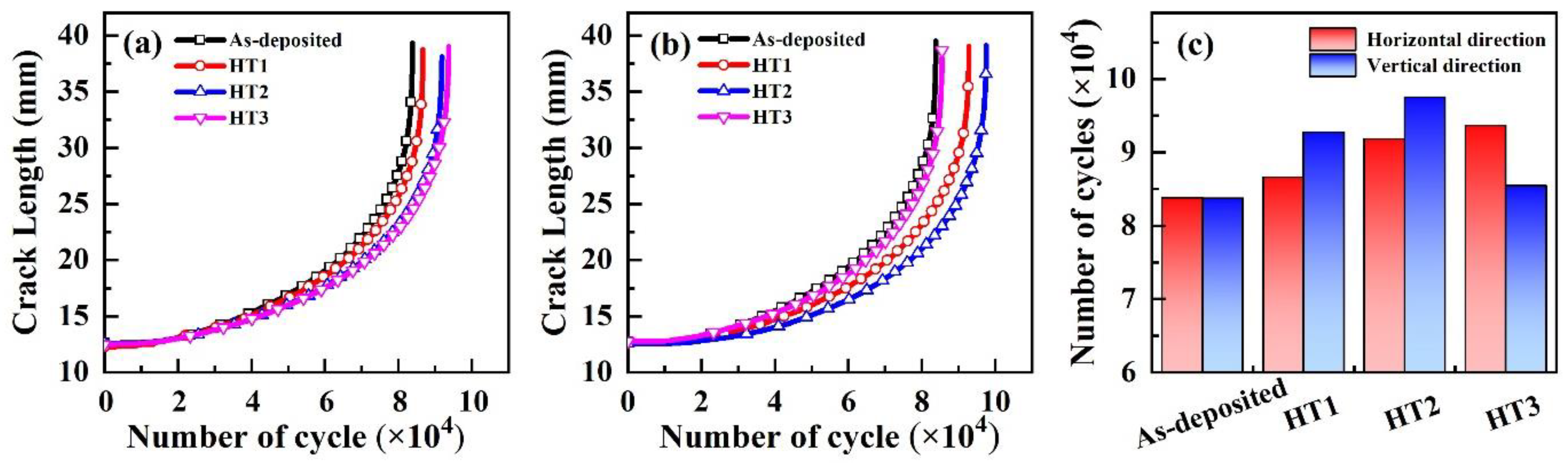
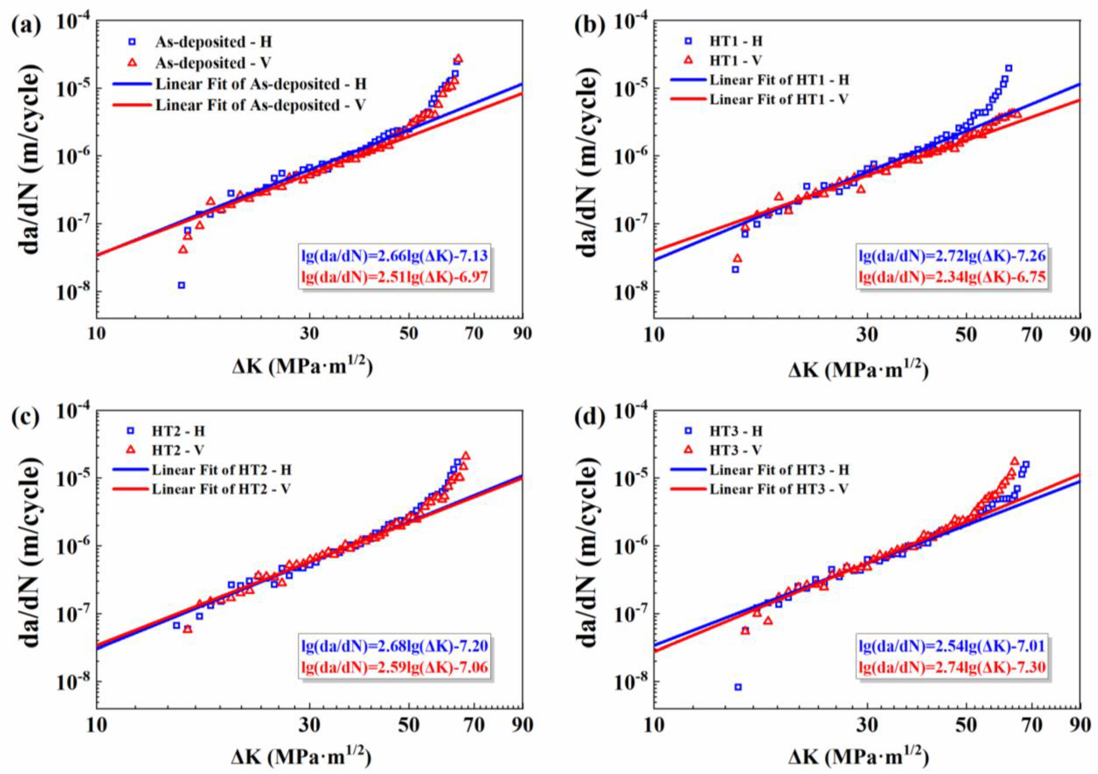
  • By comparing FCG rate of specimens in horizontal and vertical directions, it is found that the crack propagation perpendicular to the deposited direction seems to be more harmful than the parallel one.

Author Contributions

Conceptualization, F.L. and Y.Z.; methodology, F.L., Y.Z., and W.G.; software, H.Z.; validation, Y.Z. and W.G.; formal analysis, Y.Z.; investigation, B.Q. and Y.Z.; resources, P.P.; data curation, B.Q.; writing—original draft preparation, Y.Z.; writing—review and editing, J.Y., G.H. and D.Z.; visualization, J.Y.; project administration, W.G. and J.Y.; funding acquisition, W.G. and J.Y. All authors have read and agreed to the published version of the manuscript.

Funding

The authors would like to acknowledge the support of this research work from Beijing Natural Science Foundation (Grant No. 3202016), the National Natural Science Foundation of China under (Grant No. 51871010, 51775303, 52075289).

Data Availability Statement

The data presented in this study are available in article.

Conflicts of Interest

The authors declare no conflict of interest.

References

  1. Zhao, Z.; Chen, J.; Lu, X.; Tan, H.; Lin, X.; Huang, W. Formation mechanism of the α variant and its influence on the tensile properties of laser solid formed Ti-6Al-4V titanium alloy. Mater. Sci. Eng. A 2017, 691, 16–24. [Google Scholar] [CrossRef]
  2. Zhang, Q.; Chen, J.; Zhao, Z.; Tan, H.; Lin, X.; Huang, W. Microstructure and anisotropic tensile behavior of laser additive manufactured TC21 titanium alloy. Mater. Sci. Eng. A 2016, 673, 204–212. [Google Scholar] [CrossRef]
  3. Paydas, H.; Mertens, A.; Carrus, R.; Lecomtebeckers, J.; Tchuindjang, J.T. Laser cladding as repair technology for Ti–6Al–4V alloy: Influence of building strategy on microstructure and hardness. Mater. Des. 2015, 85, 497–510. [Google Scholar] [CrossRef]
  4. Thijs, L.; Verhaeghe, F.; Craeghs, T.; Van Humbeeck, J.; Kruth, J.-P. A study of the microstructural evolution during selective laser melting of Ti–6Al–4V. Acta Mater. 2010, 58, 3303–3312. [Google Scholar] [CrossRef]
  5. Oliveira, J.; LaLonde, A.; Ma, J. Processing parameters in laser powder bed fusion metal additive manufacturing. Mater. Des. 2020, 193, 108762. [Google Scholar] [CrossRef]
  6. Pham, M.-S.; Dovgyy, B.; Hooper, P.A.; Gourlay, C.M.; Piglione, A. The role of side-branching in microstructure development in laser powder-bed fusion. Nat. Commun. 2020, 11, 1–12. [Google Scholar] [CrossRef]
  7. Lopes, J.; Machado, C.M.; Duarte, V.R.; Rodrigues, T.A.; Santos, T.G.; Oliveira, J. Effect of milling parameters on HSLA steel parts produced by Wire and Arc Additive Manufacturing (WAAM). J. Manuf. Process. 2020, 59, 739–749. [Google Scholar] [CrossRef]
  8. Liu, S.; Shin, Y.C. Additive manufacturing of Ti6Al4V alloy: A review. Mater. Des. 2019, 164, 107552. [Google Scholar] [CrossRef]
  9. Oliveira, J.; Panton, B.; Zeng, Z.; Andrei, C.; Zhou, Y.; Miranda, R.; Fernandes, F.B. Laser joining of NiTi to Ti6Al4V using a Niobium interlayer. Acta Mater. 2016, 105, 9–15. [Google Scholar] [CrossRef]
  10. Xue, A.; Wang, L.; Lin, X.; Wang, J.; Chen, J.; Huang, W. Effect of boron on the microstructure and mechanical properties of Ti-6Al-4V produced by laser directed energy deposition after heat treatment. J. Laser Appl. 2020, 32, 012007. [Google Scholar] [CrossRef]
  11. Xu, W.; Brandt, M.S.; Sun, S.; Elambasseril, J.; Liu, Q.; Latham, K.; Xia, K.; Qian, M. Additive manufacturing of strong and ductile Ti–6Al–4V by selective laser melting via in situ martensite decomposition. Acta Mater. 2015, 85, 74–84. [Google Scholar] [CrossRef]
  12. Yan, M.; Yu, M.Y.A.P. An Overview of Densification, Microstructure and Mechanical Property of Additively Manufactured Ti-6Al-4V—Comparison among Selective Laser Melting, Electron Beam Melting, Laser Metal Deposition and Selective Laser Sintering, and with Conventional Powder. In Sintering Techniques of Materials; IntechOpen: London, UK, 2015. [Google Scholar]
  13. Vilaro, T.; Colin, C.; Bartout, J.-D. As-Fabricated and Heat-Treated Microstructures of the Ti-6Al-4V Alloy Processed by Selective Laser Melting. Met. Mater. Trans. A 2011, 42, 3190–3199. [Google Scholar] [CrossRef]
  14. Ter Haar, G.M.; Becker, T.H. Selective Laser Melting Produced Ti-6Al-4V: Post-Process Heat Treatments to Achieve Superior Tensile Properties. Materials 2018, 11, 146. [Google Scholar] [CrossRef] [PubMed] [Green Version]
  15. Vrancken, B.; Thijs, L.; Kruth, J.-P.; Van Humbeeck, J. Heat treatment of Ti6Al4V produced by Selective Laser Melting: Microstructure and mechanical properties. J. Alloys Compd. 2012, 541, 177–185. [Google Scholar] [CrossRef] [Green Version]
  16. Kumar, P.; Ramamurty, U. Microstructural optimization through heat treatment for enhancing the fracture toughness and fatigue crack growth resistance of selective laser melted Ti 6Al 4V alloy. Acta Mater. 2019, 169, 45–59. [Google Scholar] [CrossRef]
  17. Li, J.; Lin, X.; Wang, J.; Zheng, M.; Guo, P.; Zhang, Y.; Ren, Y.; Liu, J.; Huang, W. Effect of stress-relief annealing on anodic dissolution behaviour of additive manufactured Ti-6Al-4V via laser solid forming. Corros. Sci. 2019, 153, 314–326. [Google Scholar] [CrossRef]
  18. Wycisk, E.; Solbach, A.; Siddique, S.; Herzog, D.; Walther, F.; Emmelmann, C. Effects of Defects in Laser Additive Manufactured Ti-6Al-4V on Fatigue Properties. Phys. Procedia 2014, 56, 371–378. [Google Scholar] [CrossRef] [Green Version]
  19. Irving, P.; Beevers, C. Microstructural influences on fatigue crack growth in Ti6Al4V. Mater. Sci. Eng. 1974, 14, 229–238. [Google Scholar] [CrossRef]
  20. Leuders, S.; Thöne, M.; Riemer, A.; Niendorf, T.; Tröster, T.; Richard, H.; Maier, H. On the mechanical behaviour of titanium alloy TiAl6V4 manufactured by selective laser melting: Fatigue resistance and crack growth performance. Int. J. Fatigue 2013, 48, 300–307. [Google Scholar] [CrossRef]
  21. ASTM E8/E8M-16ae1. Standard Test Methods for Tension Testing of Metallic Materials; ASTM International: West Conshohocken, PA, USA, 2016. [Google Scholar] [CrossRef]
  22. ASTM E647-15e1. Standard Test Method for Measurement of Fatigue Crack Growth Rates; ASTM International: West Conshohocken, PA, USA, 2015. [Google Scholar] [CrossRef]
  23. Tan, X.; Kok, Y.; Tan, Y.J.; Descoins, M.; Mangelinck, D.; Tor, S.B.; Leong, K.F.; Chua, C.K. Graded microstructure and mechanical properties of additive manufactured Ti–6Al–4V via electron beam melting. Acta Mater. 2015, 97, 1–16. [Google Scholar] [CrossRef]
  24. Fu, M.; Yuan, Y.; Ma, X.; Lin, X. A study of α variant selection in laser solid forming Ti-6Al-4V. J. Alloys Compd. 2019, 792, 1261–1266. [Google Scholar] [CrossRef]
  25. Yang, J.; Yu, H.; Yin, J.; Gao, M.; Wang, Z.; Zeng, X. Formation and control of martensite in Ti-6Al-4V alloy produced by selective laser melting. Mater. Des. 2016, 108, 308–318. [Google Scholar] [CrossRef]
  26. Tan, X.; Kok, Y.; Toh, W.Q.; Tan, Y.J.; Descoins, M.; Mangelinck, D.; Tor, S.B.; Leong, K.F.; Chua, C.K. Revealing martensitic transformation and α/β interface evolution in electron beam melting three-dimensional-printed Ti-6Al-4V. Sci. Rep. 2016, 6, 26039. [Google Scholar] [CrossRef] [Green Version]
  27. Galarraga, H.; Warren, R.J.; Lados, D.A.; Dehoff, R.R.; Kirka, M.M. Fatigue crack growth mechanisms at the microstructure scale in as-fabricated and heat treated Ti-6Al-4V ELI manufactured by electron beam melting (EBM). Eng. Fract. Mech. 2017, 176, 263–280. [Google Scholar] [CrossRef] [Green Version]
  28. Kumar, P.; Prakash, O.; Ramamurty, U. Micro-and meso-structures and their influence on mechanical properties of selectively laser melted Ti-6Al-4V. Acta Mater. 2018, 154, 246–260. [Google Scholar] [CrossRef]
  29. Edwards, P.D.; O’Conner, A.; Ramulu, M. Electron Beam Additive Manufacturing of Titanium Components: Properties and Performance. J. Manuf. Sci. Eng. 2013, 135, 061016. [Google Scholar] [CrossRef]
  30. Edwards, P.G.; Ramulu, M. Effect of build direction on the fracture toughness and fatigue crack growth in selective laser melted Ti-6Al-4V. Fatigue Fract. Eng. Mater. Struct. 2015, 38, 1228–1236. [Google Scholar] [CrossRef]
  31. Rans, C.; Michielssen, J.; Walker, M.; Wang, W.; Hoen-Velterop, L.’T. Beyond the orthogonal: On the influence of build orientation on fatigue crack growth in SLM Ti-6Al-4V. Int. J. Fatigue 2018, 116, 344–354. [Google Scholar] [CrossRef]
  32. Schroeder, G.; Albrecht, J.; Luetjering, G. Fatigue crack propagation in titanium alloys with lamellar and bi-lamellar microstructures. Mater. Sci. Eng. A 2001, 319, 602–606. [Google Scholar] [CrossRef]
Figure 1. Schematics of (a) the laser solid forming processing of Ti6Al4V alloy, (b) tensile specimens, (c) compact tensile (CT) specimens, and (d) locations of specimens for characterization.
Metals 11 00346 g001
Figure 2. Microstructure of the Ti6Al4V alloy along (a) vertical direction, (b) horizontal direction, and (c) detailed observation of α phases, (d) schematic diagram of the observation position.
Metals 11 00346 g002
Figure 3. The SEM micrographs of LSFed Ti6Al4V alloy for (a) as-deposited specimens, and after (b) HT1, (c) HT2, (d) HT3 heat treatments.
Metals 11 00346 g003
Figure 4. The curves engineering stress against engineering strain of as-deposited and heat-treated specimens.
Metals 11 00346 g004
Figure 5. Crack length vs. number of cycle curve of Ti6Al4V alloy in (a) horizontal direction and (b) vertical direction, and (c) cycle life results after heat treatments.
Metals 11 00346 g005
Figure 6. FCG rate (da/dN) vs. stress intensity factor (ΔK) curves for (a) as-deposited specimens, (b) HT1 specimens, (c) HT2 specimens, and (d) HT3 specimens.
Metals 11 00346 g006
Figure 7. The side morphologies of the FCG fracture for HT1 specimens in (a) horizontal and (b) vertical directions, and (c) schematic representation of FCG along two directions, respectively.
Metals 11 00346 g007
Figure 8. Fracture morphologies for vertical FCG at a ≈28 mm: (a,b) as-deposited, (c,d) HT1, (e,f) HT2 and (g,h) HT3 specimens.
Metals 11 00346 g008
Figure 9. Distribution characteristics of fatigue striations, (a) HT1, (b) HT2, and (c) HT3 specimens.
Metals 11 00346 g009
Table 1. List of abbreviations used in this study.
AbbreviationMeaning
LSFlaser solid forming
FCGFatigue crack growth
AMAdditive manufacturing
ΔKthStress intensity threshold factor
ΔKStress intensity factor
FCFurnace cooling
OMOptical microscope
SEMScanning electron microscope
CT specimensCompact tensile specimens
CODCrack opening displacement
αGBα phases in grain boundary
αWthe Widmanstätten structure with parallel α plates
αWMIntragranular basket-weave microstructure
YSYield strength
UTSUltimate tensile strength
EBAMElectron beam additive manufacturing
da/dNFCG rate
Table 2. Specifications for heat treatments.
Heat TreatmentTemperature (°C)Hold Time (h)Method of Cooling
As-deposited
HT15502FC
HT28004FC
HT3Step 17504FC
Step 25001FC
Table 3. Microstructure summary of Ti6Al4V alloy before and after different heat treatments.
Heat Treatmentβ Phase Fractionα Phase Width (Min–Max)
As-deposited<2%0.2–1.8 μm
HT119%0.4–1.5 μm
HT28%0.3–0.9 μm
HT36%0.6–1.8 μm
Table 4. Summary of the mechanical properties of as-deposited and heat-treated Ti6Al4V alloy.
SpecimenDirectionMicrohardness (HV)YS (MPa)UTS (MPa)Elongation (%)
As-depositedH370 ± 8831 ± 6909 ± 811.5 ± 0.8
V366 ± 9789 ± 12885 ± 1112.1 ± 0.7
HT1H356 ± 5866 ± 6934 ± 411.1 ± 0.4
V355 ± 5787 ± 6862 ± 612.1 ± 1.2
HT2H344 ± 8768 ± 21837 ± 298.2 ± 1.6
V347 ± 10711 ± 13809 ± 2012.7 ± 1.0
HT3H352 ± 9786 ± 17852 ± 1912.4 ± 0.4
V348 ± 11740 ± 5821 ± 913.2 ± 0.6
Table 5. Material constants m and C of the as-deposited and heat-treated specimens.
SpecimensDirectionmC
As-depositedH2.667.39 × 10−8
V2.511.07 × 10−7
HT1H2.725.44 × 10−8
V2.341.79 × 10−7
HT2H2.686.36 × 10−8
V2.598.71 × 10−8
HT3H2.549.80 × 10−8
V2.744.98 × 10−8
Publisher’s Note: MDPI stays neutral with regard to jurisdictional claims in published maps and institutional affiliations.

