Article

Normalized Parameter Creep Model of DD6 Nickel-Based Single Crystal Superalloy

1
School of Energy and Power Engineering, Beihang University, 37 Xueyuan Road, Haidian District, Beijing 100191, China
2
Jiangxi Research Institute, Beihang University, North Block, Building 8, Zhongxing Industrial Park, No. 688 Aixi North Road, Gaoxing District, Nanchang 330096, China
3
Science and Technology on Scramjet Laboratory, Beijing Power Machinery Institute, Beijing 100074, China
*
Author to whom correspondence should be addressed.
Metals 2021, 11(2), 254; https://doi.org/10.3390/met11020254
Submission received: 8 December 2020 / Revised: 23 January 2021 / Accepted: 24 January 2021 / Published: 2 February 2021
(This article belongs to the Special Issue Creep and Deformation of Metals and Alloys at Elevated Temperatures)

Abstract

:
For nickel-based single crystal superalloy DD6 (AECC Beijing Institute of Aeronautical Materials, Beijing, China) material, a method for predicting creep rupture time was proposed based on a newly defined equivalent stress method. An anisotropic creep model for describing the orientation-dependent creep behavior and lifetime of a nickel-based single crystal superalloy was proposed. The creep subroutine was written based on the proposed nickel-based single crystal creep model. The stability of the model was improved by adjusting the iterative algorithm. The creep calculation results in [001], [011], and [111] loading directions were compared with the experimental results. The accuracy of the calculation results by the nickel-based single crystal creep subroutine was verified. The initial time step and maximum time step of the creep subroutine were studied.

1. Introduction

Nickel-based single crystal superalloy turbine blades are one of the key technologies for aero engines since the 1980s. Over the past dozen years, the first, second, and third generation of nickel-based single crystal superalloys have been developed and applied successively, to enhance the temperature resistance of aero-engine turbine rotor blade materials by nearly 90 °C [1] compared with directional solidification superalloys. At present, almost all advanced aero-engine turbine rotor blades have adopted nickel-based single crystal superalloy.
In the 1970s, the United States first used PWA1422 (Pratt & Whitney Group, Connecticut, United States) directional blades on military engines, and then on civil aircrafts. In the 1980s, PWA1480 (Pratt & Whitney Group, Connecticut, United States) single crystal blades were used in the F100 engines. Since then, directional and single crystal blades have become important features of various advanced engines. The development of directional solidification technology has greatly improved the high temperature capability of cast superalloys. After the 1980s, the thrust-to-weight ratio was increased from 8 to 10. The first-generation single crystal superalloy PWA1480 was used on turbine blades. Subsequently, the second-generation single crystal superalloy PWA1484 (Pratt & Whitney Group, Connecticut, United States) and CMSX-4 (Cannon Muskegon Corporation, Muskegon, United States) were used. The 100 h rupture strength reached 140 MPa at 1100 °C. After the 1990s, the third-generation single crystal alloys RenéN6 and CMSX-10 (Cannon Muskegon Corporation, Muskegon, United States) were developed. The melting point, initial melting temperature and service temperature of the alloys were increased by the addition of rhenium, tungsten, and tantalum. The third-generation single crystal superalloy CMSX-10 has an obvious advantage in creep strength compared to the second-generation single crystal superalloy CMSX-4. The fourth-generation single crystal alloy RR3010 (Rolls-Royce, City of Westminster, United Kingdom) was developed by the British RR company in recent years. RR3010 has a high temperature capacity of about 100 °C higher than that of directional alloys.
Chinese research on nickel-based single crystal alloys and their processes began in the 1970s, leading to the development of the DD3 (AECC Beijing Institute of Aeronautical Materials, Beijing, China) nickel-based single crystal alloy first for aero-engine turbine rotor blade. It has been successfully used in engine high-pressure turbine rotor blades and has passed the high-speed test. Due to the lack of breakthroughs in key technologies, the intermetallic compound-based alloys and ceramic materials, which are considered to be the next-generation promising replacement materials for turbine rotor blades, still have not entered the engineering stage. It is expected that for a long period of time in the future, nickel-based single crystal superalloy will still be the most important rotor blade material for advanced gas turbine engines [2].
The prerequisite for the strength and life analysis of nickel-based single crystal turbine rotor blades is the material constitutive model. The research on constitutive models can be divided into two categories in terms of methods: The macroscopic models based on phenomenology and the microscopic models based on crystal slip theory.
(1) The macroscopic model uses an anisotropy tensor to describe the inelastic anisotropic deformation, without considering the specific deformation process of the single crystal. In literature [3], from the study of the fine and microstructural changes and damage characteristics of the creep process for nickel-based single crystal alloy, a two-parameter creep life prediction model based on cavity damage and material degradation as damage parameters was established. The creep rupture time of V-notch DD6 rod specimens was predicted based on the damage theory in literature [4]. The creep damage and fracture mechanism were studied for DD6 material under multiaxial stress state in literature [5]. Under the thermodynamics framework [6], the evolution equation of single crystal damage was derived by introducing damage variables related to dissipation power and damage state, and a macroscopic anisotropic viscoplastic damage model of nickel-based single crystal was established. In literature [7], by the method of combining damage mechanics and viscoplasticity theory, the viscoplastic unified constitutive model of orthotropic material was modified and generalized, and the orthotropic viscoplastic unified constitutive model under the interaction of creep and fatigue loads was established.
(2) The microscopic model considers the complex process of nickel-based single crystal deformation, and converts the accumulated crystal slip stress and strain into the global coordinate system to obtain inelastic deformation characteristics. The early work of crystal plasticity theory is the pioneering work of Taylor [8] and others. Their work clearly shows that metal plastic deformation is closely related to its crystallographic structure and has microstructure sensitivity. Based on the work of Taylor, Hill, and Rice [9] performed a rigorous mathematical description of the plastic deformation geometry and kinematics of the crystal, and extended the model to a rate-independent viscoplastic finite deformation analysis. Asaro and Rice [10] and Havner [11], among others, have further developed the crystal plastic constitutive theory and applied it to rate-dependent viscoplastic analysis.
Regarding the development of constitutive model for nickel-based single crystal materials, recent work is represented by literature [12,13]. However, the models are relatively complicated. In literature [14], the mapping method was used to simulate the creep deformation of different orientations comparatively precisely, nevertheless, the creep deformation simulation at different temperatures cannot be achieved. A more accurate creep deformation simulation of nickel-based single crystal materials at different temperatures was achieved in literature [15,16], except that only the [001] orientation was experimentally verified. In literature [17], the creep deformation simulation of the nickel-based single crystal turbine blade model was carried out, although the model still cannot consider multiple temperatures at the same time. In literature [18], a constitutive model for the mechanical behavior of single-crystalline superalloys at high temperatures has been developed. The model relies on the slip system theory and is able to predict rafting and its influence on plastic flow. In literature [19], new internal variables representing the microstructural changes under those specific thermal loadings have been introduced in the framework of crystal plasticity using a macroscopic approach to account for the transient creep behavior induced by microstructure changes. In literature [20], a homogenization method including modified γ / γ microstructure area surrounding pores and topologically close-packed (TCP) phase particles was developed and correlated to creep life. In literature [21], a modified crystal plasticity constitutive model considering microstructure evolution is developed. In the literature [22], a physics-based model is proposed to predict the γ / γ 
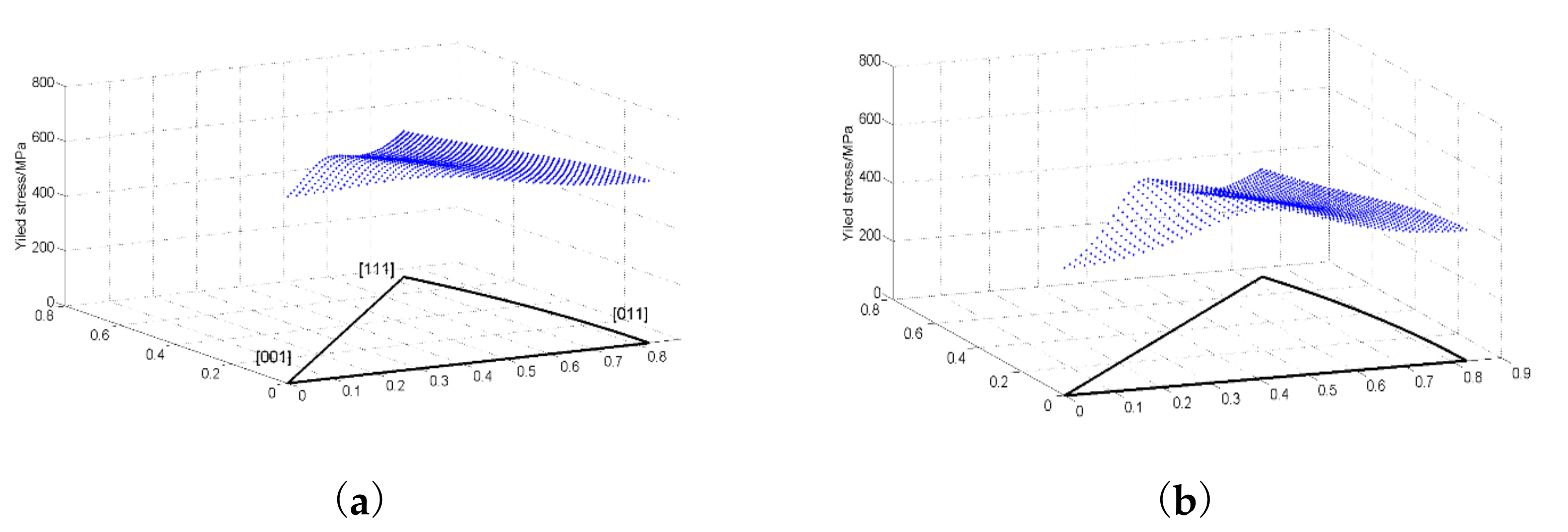
microstructure evolution of single crystal (SC) superalloy at medium temperature and high stress level. The anisotropy of mechanical properties of nickel-based single crystal materials [5,23] is still a major challenge in the deformation simulation of aerospace engine turbine nickel-based single crystal blades.
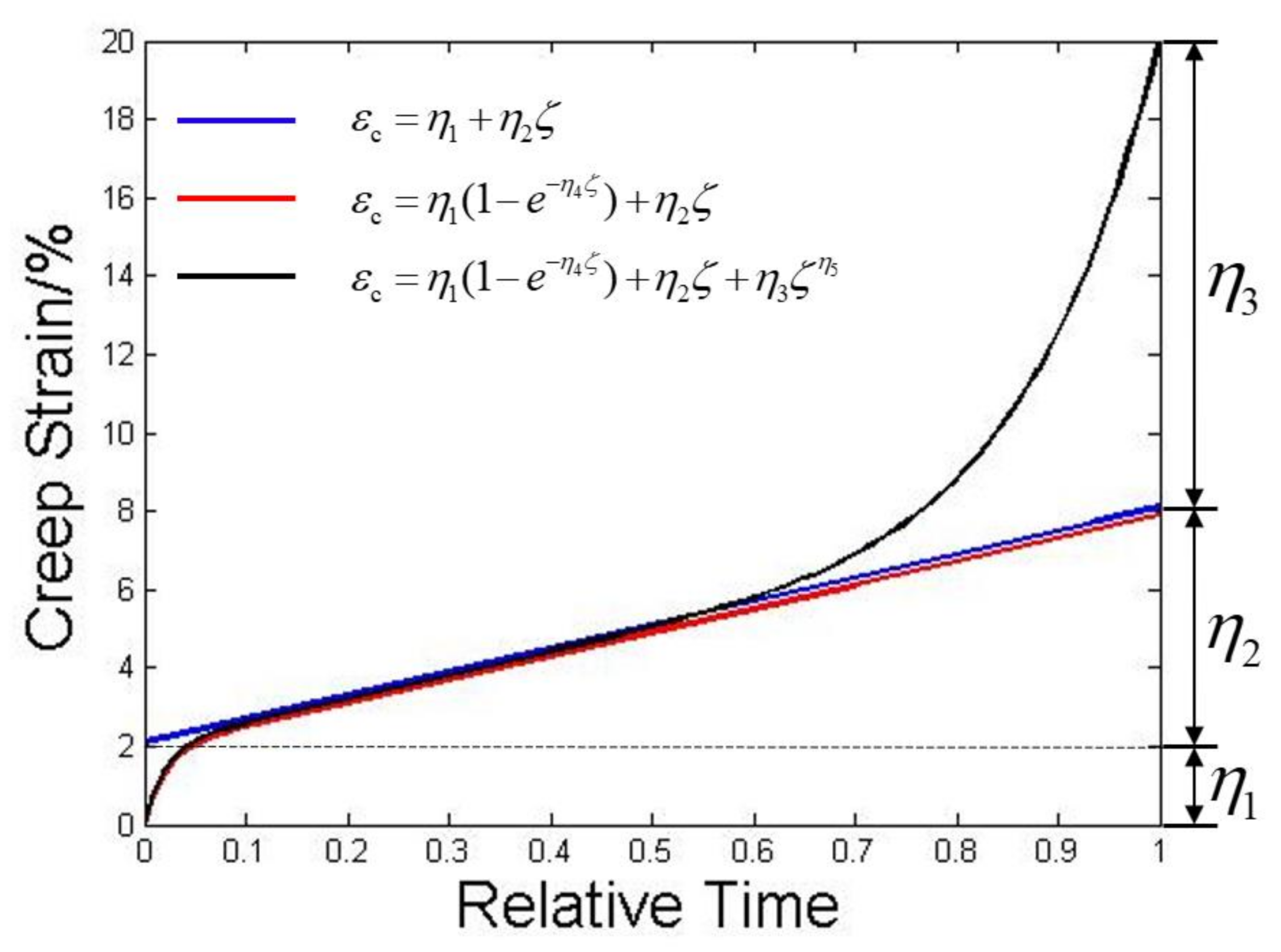
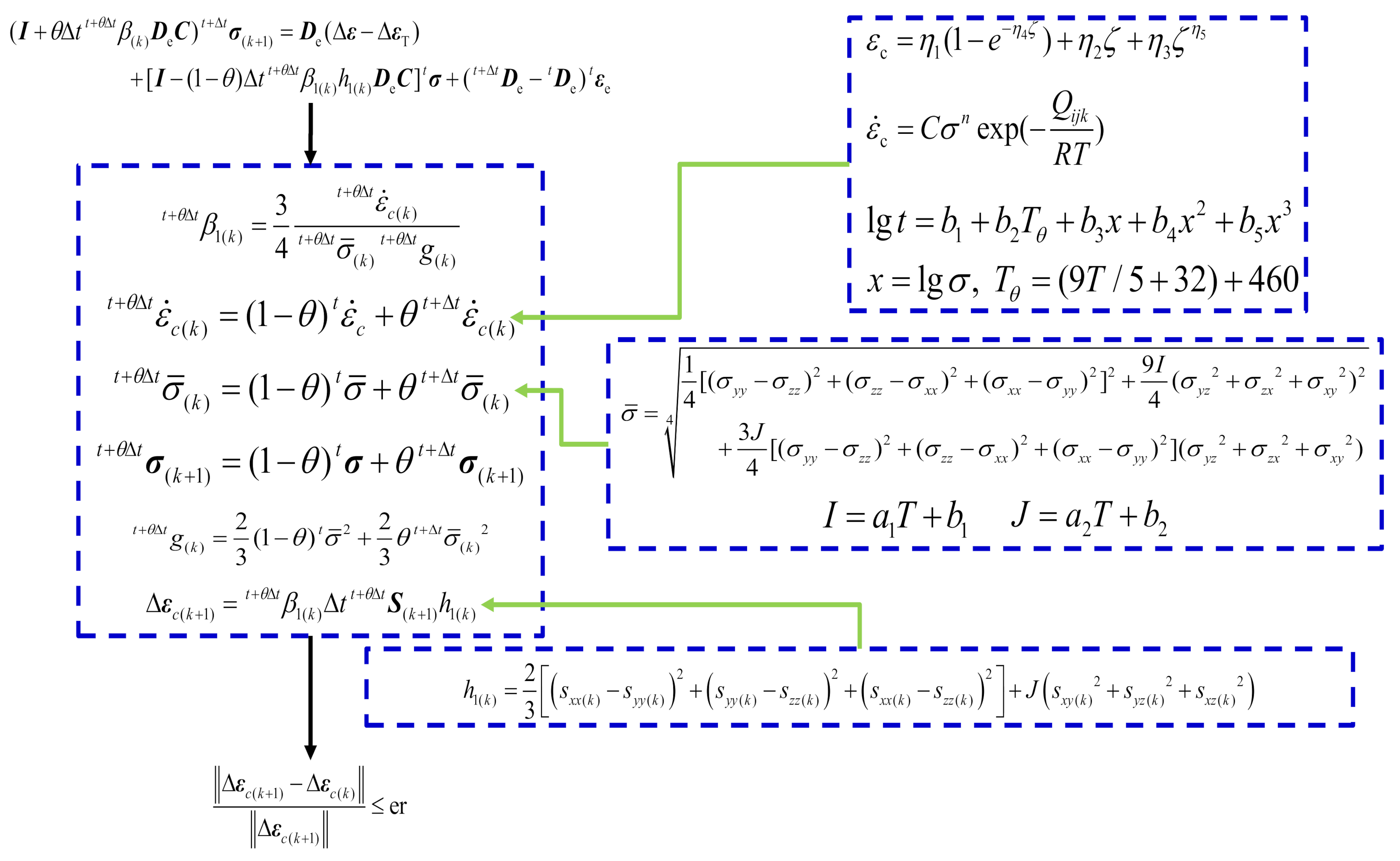
Creep models considering nickel-based single crystal orientation in this paper include: Second-stage creep strain rate prediction, creep model establishment and parameter fitting, creep rupture time prediction, flow law based on newly defined equivalent stress, creep model algorithm, usermat subroutine writing and model verification. Since the creep strain–time curve is incomplete, and is highly dispersive at different crystal orientations and temperatures, this paper has not proposed a more accurate model to describe the creep curves at different temperatures in different crystal orientations. According to literature [
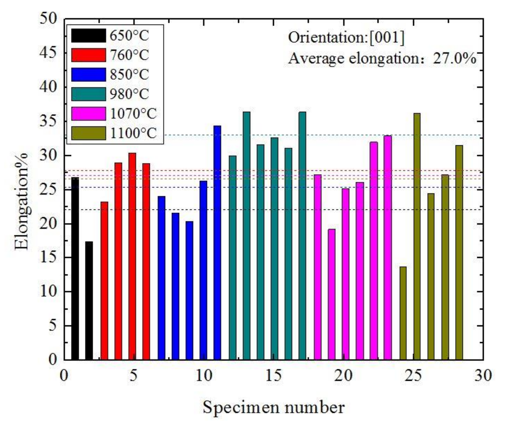
24], the creep curves in different orientations have similar shapes. Assuming that the creep curves in different orientations have similar shapes, the creep deformation behavior of all orientations was described with the creep curve shape of [001] orientation.

2. Nickel-Based Single Crystal Creep Model

2.1. Basic Characteristics of DD6 Material

DD6 material is a second-generation nickel-based single crystal superalloy with a melting point of 1370.5 °C. In view of the cubic symmetry of nickel-based single crystal materials, the elastic properties of DD6 material [24] at different temperatures are shown in Table 1.
For the yield strength data in different orientations at different temperatures, the yield strength under the calculation condition can be obtained by linear interpolation or polynomial parameter fitting. The uniaxial tensile experimental data [24] for the DD6 material in [001], [011], and [111] three orientations are shown in Table 2. The [011] direction experience a higher yield strength above 1070 °C, instead of at lower temperatures. The possible reason is the scatter of the database. For each temperature in the literature [24], only one or two samples were used for the experiment. The model in this paper only uses the [001] oriented yield strength data.
The predicted tensile yield strength of DD6 material with different orientations at different temperatures is shown in Figure 1. The plane composed of the x and y axes corresponds to the standard projection plane. The fitting function used in Figure 1 is Equation (7). It will be described in detail in Section 2.4.
It can be observed from the database that the yield strength of DD6 material tends to isotropic with increase of temperature at higher temperature. The yield strengths corresponding to different orientations are not much different. Due to the particularity of the experimental data for the 1070 °C, the yield strength in the [111] direction is the smallest, and in the [011] direction is the largest. The yield surface shape corresponding to the yield function is the shape of Figure 1b. The special data leads to the maximum yield strength in the near [001] direction. This abnormal situation requires more material data for further verification.

2.2. Second Stage Creep Strain Rate Prediction

The creep strain–time curve is processed to obtain the second stage creep strain rate of the corresponding creep under different orientations, different temperatures, and stress levels, and fit it by the following activation energy formula [25]. The second stage creep strain rate is the minimum creep rate, which is the steady-state creep rate.
ε ˙ c = C σ n exp ( Q i j k R T )
ε ˙ c is the creep strain rate of second stage of creep, C is the material constant, n is the stress exponent, and Q i j k is the creep activation energy for different orientations. R is the Boltzmann constant, where R = 0.0083145 kJ / ( mol K ) . The results of the fitting parameters are shown in Table 3. Base on the potential different deformation mechanisms in this large temperature window, the stress exponent n evolves for physical reasons. Due to the lack of material data, the same n is used in this article. The second stage creep strain rate corresponding to different orientations is calculated and compared with the experimental results [24]. The percentage error is defined as ε ˙ c ε ˙ c , Fitting ε ˙ c + ε ˙ c , Fitting × 100 % . Only the [001] orientation results are listed here, see Table 4. The maximum percentage error of the prediction results is 25.2% at 980 °C and 200 MPa. The percentage error of most results is less than 20%. This is acceptable for engineering.

2.3. Creep Model Establishment and Parameters Fitting

The creep strain–time curves under different orientations, temperatures, and stress levels were fitted using the creep equation [26] ε c = η 1 ( 1 e η 4 ζ ) + η 2 ζ + η 3 ζ η 5 . ζ = t t c is dimensionless time, t c is the lifetime at a given temperature and stress, and ζ 0 , 1 . η i i = 1 , 2 , 3 , 4 , 5 are material-dependent parameters, which are a function of dimensionless stress σ σ 0.2 and dimensionless temperature T T m . The creep equation describes the shape of the creep curve, as shown in Figure 2. The three terms of the equation can respectively describe the three stages of creep. The parameters η 1 and η 4 describe the size and shape of the first stage of creep respectively. There is η 2 = ε ˙ c , Fitting × t c . ε ˙ c , Fitting is the strain rate of the second stage creep. t c is the creep rupture time of the corresponding orientation, temperature, and stress level. The parameter η 2 is a strain amplitude. It artificially corresponds to the slope value of the blue line in Figure 2, since the abscise axis is a relative representation of the time. The parameters η 3 , η 5 describe the size and shape of the third stage creep. δ c is the creep elongation, where δ c = η 1 + η 2 + η 3 , and thus η 3 = δ c η 1 ( 1 e η 4 ) η 2 . Only the first stage and portion of the second stage creep strain–time curve data of DD6 material are available, with the missing information of the third stage creep. Referring to the fitting data of the model parameter η 5 of other materials [26], the value of this parameter should make the third stage of creep curve show a rapid upward trend. Considering the stability of the program and the less importance of the third-stage creep, η 5 is taken as 8.0 in this paper.
The five parameters in the creep model are taken the natural logarithm, and they are considered to be dependent on temperature and stress, thus having the following form:
ln η i = a i + b i T T m + c i σ σ 0.2 + d i T T m σ σ 0.2 .
In the formula, η i ( i = 1 , 2 , 3 , 4 , 5 ) are five parameters in the creep model, T T m is the normalized temperature according to the melting point, and σ σ 0.2 is the normalized stress about to the yield strength, where the unit of T is K, the unit of σ is MPa. Due to the incomplete creep data of DD6 material, the parameter δ c is taken as 0.27, the parameter η 5 is taken as 8.0, and there is η 2 = ε ˙ c , Fitting × t c , η 3 = δ c η 1 ( 1 e η 4 ) η 2 . Among the five parameters in the creep model, only the [001] orientation creep parameter fitting results are listed in this paper. The fitting results of the creep curve parameters under different temperatures and stress levels in [001] orientation are shown in Table 5. Only the parameters η 1 and η 4 need to be fitted using Formula (3). The fitting results of the [001] orientation creep model parameters are shown in Table 6. Finally, the fitting results of the normalized creep curve under different temperature and stress levels of [001] orientation are shown in Figure 3. In these figures the normalized experimental time ranges from 0 to 0.4, so the first stages of creep are described. The creep fitting curves under different temperatures and stress levels of [001] orientation are shown in Figure 4. There is a certain error of creep curve fitting result in [001] orientation at 980 °C, and the creep curve fitting results of [001] orientation at 760 °C, 850 °C and 1070 °C are better. One possible reason is that the value of n and Q i j k are not constant with the temperature and stress level. This difference requires more data to verify.
Finally, the creep three-stage model in reference [26] is
ε c = η 1 ( 1 e η 4 ζ ) + η 2 ζ + η 3 ζ η 5 .
If only the [001] orientation of the nickel-based single crystal material is considered, this paper combines the creep data of the nickel-based single crystal DD6 material to modify the three-stage creep model to
ε c = η 1 ( 1 e η 4 ζ ) + C σ n e ( Q R T ) t c ζ + ( δ c C σ n e ( Q R T ) t c η 1 ( 1 e η 4 ) ) ζ η 5 .
Further, the above formula can be simplified as
ε c = η 1 ( 1 e η 4 ζ ) + C σ n e ( Q R T ) t c ( ζ ζ η 5 ) + ( δ c η 1 ( 1 e η 4 ) ) ζ η 5 .

2.4. Creep Rupture Life Prediction

Durable stress–life curve equation (M-S) [24]
lg t = g 1 + g 2 T + g 3 x + g 4 x 2 + g 5 x 3
where T = ( 9 / 5 θ + 32 ) + 460 , the unit of θ is °C. There is x = lg σ , the unit of σ is MPa. The durable stress–life curve equation parameter fitting results [24] of DD6 material in the [001], [011], and [111] orientations are shown in Table 7. The creep rupture elongation of [001] orientation is analyzed, as shown in Figure 5, in which the different colors correspond to different temperatures. The stress level of the same color gradually increases along the positive direction of the x axis. The creep rupture elongations at different temperatures take the mean value. It can be found that the creep rupture elongation is dispersive under different temperatures and different stress levels. The correlation between the creep rupture elongation and stress level is not obvious at the same temperature. The correlation between the creep rupture elongation and temperature is not obvious. In view of the limited creep curves data, it is impossible to get enough data of the third stage creep. In this paper, the creep rupture elongation δ c in the [001] direction of the DD6 material is taken as 27.0%.
A nickel-based single crystal yield criterion is proposed, which can be written into the following form without considering the asymmetry of tension and compression.
( s x x 2 + s y y 2 + s z z 2 ) 2 + I ( s x y 2 + s y z 2 + s x z 2 ) 2 + J ( s x x 2 + s y y 2 + s z z 2 ) ( s x y 2 + s y z 2 + s x z 2 ) = k 4
According to the uniaxial tensile test data of three different orientations [001], [011] and [111], the corresponding yield strength σ Y [ 001 ] , σ Y [ 011 ] and σ Y [ 111 ] in three orientations at different temperatures of the nickel-based single crystal material can be obtained. Furthermore, the yield function parameters k 4 = 4 9 σ Y [ 001 ] 4 , I = 4 σ Y [ 001 ] 4 σ Y [ 111 ] 4 and J = 32 3 σ Y [ 001 ] 4 σ Y [ 011 ] 4 2 3 6 σ Y [ 001 ] 4 σ Y [ 111 ] 4 can be obtained. All the parameters in the yield function are dimensionless parameters. Of course, the parameters in the function can also be obtained from the tensile or torsional yield strengths of other different orientations. It is considered that the yield surface and the potential energy surface have similar shapes, thus the above formula is applied to the creep deformation process of the nickel-based single crystal material.
Using the durable stress–life curve equation and the DD6 material parameters, the durability stresses at different temperatures corresponding to different lifetimes in different crystal orientations are obtained. Combined with the yield function, the durable stress–life data is calculated to obtain the parameters I , J , k for different given creep rupture lifetimes at different temperatures, see Table 8. The parameters for the given different creep rupture lifetimes are averaged, and the parameters I , J are linearly regressed to temperature, as shown in Figure 6. As the temperature exceeds 1100 °C and approaches the melting point of the material, the parameters I , J all approach 4, that is, the directionality of the material properties will gradually become insignificant. The results obtained by the method in this paper show this trend. However, both the values will diverge at higher temperatures. J > I at low temperature and J < I at very high temperature. Finally, using the regression coefficients of the obtained parameters I , J and the durable stress–life curve equation parameters in the [001] orientation, the durability life prediction of the nickel-based single crystal material can be performed. The durability life prediction results of different temperatures and different orientations are shown in Table 9. The life prediction results are better.
The prediction results of the creep rupture time corresponding to different crystal orientations and different temperatures are shown in Figure 7. In the figure, the black, blue, and red solid lines respectively correspond to the results of durability life experiment under different temperatures and stress levels in [001], [011], and [111] orientations. In Figure 7d, as the stress further decreases, the creep fracture time of the blue solid line decreases in the opposite direction. This is obviously inconsistent with reality, so the second half is drawn as a straight line. The blue and red dashed lines correspond to durability life prediction results at different temperatures and stress levels in the [011] and [111] orientations. The partial data point of durability life prediction results in [011] orientation at 760 °C and 850 °C are poor. The durability life prediction results in [011] orientation at other temperatures and in [111] orientation are better, both within the triple dispersion band. However, due to the dispersion of the material, the creep durability life has a large dispersion under the same condition, and there is a phenomenon that individual data points deviate from the prediction result. Only for time to rupture, there is no creep curve adequately described for orientations different from [001].

2.5. Flow Rule Based on Newly Defined Equivalent Stress

Based on the newly defined yield function form, the yield function without considering the asymmetry of tension and compression can be written into the following form
f = ( s x x 2 + s y y 2 + s z z 2 ) 2 + I ( s x y 2 + s y z 2 + s x z 2 ) 2 + J ( s x x 2 + s y y 2 + s z z 2 ) ( s x y 2 + s y z 2 + s x z 2 ) .
Among them, I , J are yield function parameters, s i j is the partial stress component. Assuming that the plastic potential energy surface has the same shape as the yield surface, thus
g = ( s x x 2 + s y y 2 + s z z 2 ) 2 + I ( s x y 2 + s y z 2 + s x z 2 ) 2 + J ( s x x 2 + s y y 2 + s z z 2 ) ( s x y 2 + s y z 2 + s x z 2 ) .
Since the plastic strain increment is d ε i j p = d λ g σ = d ε ¯ p σ ¯ g σ , combined with the newly defined yield function form, the above formula can be further expanded to
d ε i j p = 3 4 d ε ¯ p σ ¯ g σ x x = 3 4 d ε ¯ p σ ¯ 1 g s i j 2 3 s x x s y y 2 + s y y s z z 2 + s x x s z z 2 + J s x y 2 + s y z 2 + s x z 2   ( i = j )
d ε i j p = 3 4 d ε ¯ p σ ¯ g σ x y = 3 4 d ε ¯ p σ ¯ 1 g s i j 2 J 3 s x x s y y 2 + s y y s z z 2 + s x x s z z 2 + 2 I s x y 2 + s y z 2 + s x z 2   ( i j ) .
In the above formula, ε ¯ p is the equivalent plastic strain, and σ ¯ is the Mises equivalent stress. Similarly, the creep strain increment expression d ε i j p = d λ g σ = d ε ¯ c σ ¯ g σ can be obtained, which is further expanded as
d ε i j c = 3 4 d ε ¯ c σ ¯ g σ x x = 3 4 d ε ¯ c σ ¯ 1 g s i j 2 3 s x x s y y 2 + s y y s z z 2 + s x x s z z 2 + J s x y 2 + s y z 2 + s x z 2 ( i = j )
d ε i j c = 3 4 d ε ¯ c σ ¯ g σ x y = 3 4 d ε ¯ c σ ¯ 1 g s i j 2 J 3 s x x s y y 2 + s y y s z z 2 + s x x s z z 2 + 2 I s x y 2 + s y z 2 + s x z 2 ( i j ) .
In the above formula, ε ¯ c is the equivalent creep strain. The shear strain increment is the tensor shear strain.

3. Creep Model Algorithm and Subroutine

3.1. Creep Model Algorithm

Using the virtual displacement principle in incremental form, the stress–strain relationship adopted is divided into two forms [27], elastic matrix and elastoplastic matrix, which form the iterative solution equations of constant stiffness and variable stiffness respectively. The formulas are as follows
d σ i j = D i j k l e t ( d ε k l d ε k l p d ε k l T d ε k l c ) + d D i j k l e ε k l e
d σ i j = D i j k l ep t ( d ε k l d ε k l T d ε k l c ) + d σ i j 0 .
The usermat subroutine written in this paper adopts the method of constant stiffness matrix.
First, it is obtained by the formula σ ( k + 1 ) t + Δ t σ 0 = D e ( Δ ε Δ ε T Δ ε c ( k + 1 ) ) [27] as
( I + θ Δ t t + θ Δ t β ( k ) D e C ) σ ( k + 1 ) t + Δ t = D e ( Δ ε Δ ε T ) + [ I ( 1 θ ) Δ t t + θ Δ t β ( k ) D e C ] σ t + ( D e t + Δ t D e t ) ε e t
The linear equations need to be solved iteratively, where k = 0 , 1 , 2 , , C = [ I 1 3 m m T ] , m T = [ 1 , 1 , 1 , 0 , 0 , 0 ] . The algorithm is stable, when there is 1 / 2 θ 1 . Among them, there are
β ( k ) t + θ Δ t = 3 2 ε ˙ c ( k ) t + θ Δ t σ ¯ ( k ) t + θ Δ t
Δ ε c ( k + 1 ) = 3 2 ε ˙ c ( k ) t + θ Δ t Δ t σ ¯ ( k ) t + θ Δ t S ( k + 1 ) t + θ Δ t
ε ˙ c ( k ) t + θ Δ t = ( 1 θ ) ε ˙ c t + θ ε ˙ c ( k ) t + Δ t
σ ¯ ( k ) t + θ Δ t = ( 1 θ ) σ ¯ t + θ σ ¯ ( k ) t + Δ t
σ ( k + 1 ) t + θ Δ t = ( 1 θ ) σ t + θ σ ( k + 1 ) t + Δ t
S ( k + 1 ) t + θ Δ t = C σ ( k + 1 ) t + θ Δ t .
The original iteration formulas for the model proposed in this paper are modified as
Δ ε c ( k + 1 ) = 3 4 ε ˙ c ( k ) t + θ Δ t Δ t σ ¯ ( k ) t + θ Δ t g ( k ) t + θ Δ t S ( k + 1 ) t + θ Δ t h 1 ( k ) = β 1 ( k ) t + θ Δ t Δ t S ( k + 1 ) t + θ Δ t h 1 ( k ) ( i   =   1 ,   2 ,   3 )
Δ ε c ( k + 1 ) = 3 8 ε ˙ c ( k ) t + θ Δ t Δ t σ ¯ ( k ) t + θ Δ t g ( k ) t + θ Δ t S ( k + 1 ) t + θ Δ t h 2 ( k ) = β 2 ( k ) t + θ Δ t Δ t S ( k + 1 ) t + θ Δ t h 2 ( k ) ( i   =   4 ,   5 ,   6 ) .
In the formulas, σ ¯ ( k ) t + θ Δ t adopts the equivalent stress form proposed in this paper. β 1 ( k ) t + θ Δ t and β 2 ( k ) t + θ Δ t can be obtained by the following formula
β 1 ( k ) t + θ Δ t = 3 4 ε ˙ c ( k ) t + θ Δ t σ ¯ ( k ) t + θ Δ t g ( k ) t + θ Δ t
β 2 ( k ) t + θ Δ t = 3 8 ε ˙ c ( k ) t + θ Δ t σ ¯ ( k ) t + θ Δ t g ( k ) t + θ Δ t .
Among them, g ( k ) t + θ Δ t can be obtained by the following formula
g ( k ) t + θ Δ t = ( 1 θ ) g t + θ g ( k ) t + Δ t = 2 3 ( 1 θ ) σ ¯ 2 t + 2 3 θ σ ¯ ( k ) 2 t + Δ t .
The variables h 1 ( k ) and h 2 ( k ) are respectively obtained by the following formula
h 1 ( k ) = 2 3 s x x ( k ) s y y ( k ) 2 + s y y ( k ) s z z ( k ) 2 + s x x ( k ) s z z ( k ) 2 + J s x y ( k ) 2 + s y z ( k ) 2 + s x z ( k ) 2
h 2 ( k ) = J 3 s x x ( k ) s y y ( k ) 2 + s y y ( k ) s z z ( k ) 2 + s x x ( k ) s z z ( k ) 2 + 2 I s x y ( k ) 2 + s y z ( k ) 2 + s x z ( k ) 2 .
The other parameters in Formulas (23) and (24) are as follows
ε ˙ c ( k ) t + θ Δ t = ( 1 θ ) ε ˙ c t + θ ε ˙ c ( k ) t + Δ t
σ ¯ ( k ) t + θ Δ t = ( 1 θ ) σ ¯ t + θ σ ¯ ( k ) t + Δ t
σ ( k + 1 ) t + θ Δ t = ( 1 θ ) σ t + θ σ ( k + 1 ) t + Δ t
S ( k + 1 ) t + θ Δ t = C σ ( k + 1 ) t + θ Δ t .
The convergence criterion is Δ ε c ( k + 1 ) Δ ε c ( k ) Δ ε c ( k + 1 ) er . Using the above iterative method to update the stress, the process of main program calling the subroutine and the subroutine iteration process is shown in Figure 8. The direct correlation variable with the nickel-based single crystal creep model during the iterative process is the equivalent creep strain rate ε ˙ c . The time unit of the subroutine is unified as h.
The subroutine calculation flow chart corresponds to the iterative solution part in the subroutine in Figure 8, as shown in Figure 9. Only the algorithms corresponding to normal stress and normal strain are listed in the figure. The algorithms corresponding to shear stress and shear strain are similar so they are not listed. The iterative process mainly includes four modules: The main iterative module, the creep strain rate solving module, the newly defined equivalent stress solving module and the intermediate variable solving module.

3.2. Subroutine Verification

(1)
Creep calculation results in [011] and [111] orientations
The creep calculation results of [001] orientation loading are shown in the corresponding results in Section 2.3. The creep calculation results of [011] and [111] orientations loading are shown in Figure 10. Creep calculation results in [001] orientation at 760 °C and 980 °C are conservative, and creep calculation results at 850 °C and 1070 °C are in good agreement with experimental results. Creep calculation results in [011] orientation at 760 °C and 980 °C are conservative, and the creep calculation results at 850 °C are close to experimental results. Creep calculation results in [111] orientation at 980 °C and 1070 °C are conservative, and creep calculation results at 850 °C are close to experimental results. The creep calculation results in [011] and [111] orientations are generally conservative.
(2)
Influence of time step on calculation accuracy
Firstly, the influence of the maximum time step on the creep calculation results is investigated. The creep calculation results in [001] orientation with loading of 500 MPa at 850 °C are selected, and the initial time steps 10 5 h are set to all. The creep calculation results with different maximum time steps are compared with the experimental results, as shown in Figure 11 (1). The creep calculation results are the same for different maximum time steps. The conclusion can be drawn that the maximum time step has no effect on the creep calculation results, with a certain range 10 0 10 3 h. To further investigate the influence of the initial time step on the creep calculation results, the creep calculation results in [001] orientation with loading of 500 MPa at 850 °C are selected again. The maximum time step is 10 3 h. The creep calculation results with different initial time steps are compared with experimental results, as shown in Figure 11. The creep calculation results for different initial time steps are the same. It can be seen that the creep calculation results are not affected by the initial time step when the initial time step is smaller than 10 3 h.
Due to the large number of nickel-based single crystal hollow turbine blade elements, it is necessary to select a larger initial time step and maximum time step to improve the calculation efficiency. However, in the actual calculation process, a larger initial time step often leads to non-convergence in parts of Gaussian integration point. To ensure the convergence of most Gaussian integration points, the initial time step shoule not be too large. At the same time, the creep convergence curve of the initial stage of creep calculation (0–0.1 h) oscillates greatly, and the subsequently creep calculation convergence curve is relatively stable. Hence, in the initial stage, the initial time step is 10 5 h and the maximum time step is 10 3 h. The initial time step 10 4 h is selected for the subsequent creep calculation, with the maximum time step 1 h.

4. Conclusions

(1)
Based on the proposed equivalent stress that can characterize the orientation characteristics of nickel-based single crystals, the creep rupture life in different orientations is predicted. The corresponding flow rule based on the proposed equivalent stress is derived. Finally, creep constitutive model and model algorithm for single crystal materials are proposed.
(2)
Creep calculation results in [001], [011], and [111] orientations are compared with experimental results, and the accuracy of calculation results for the nickel-based single crystal creep subroutine is verified.
(3)
By writing the usermat subroutine, the high precision creep deformation simulation of the structural parts for nickel-based single crystal materials at different temperatures and different stress levels can be realized, and the subroutine calculation efficiency meets engineering application.
(4)
Initial time step and maximum time step of the usermat creep subroutine are studied, and some suggestions for the selection of initial time step and maximum time step are provided.

Author Contributions

Conceptualization, Y.L., D.W. and Y.W.; methodology, D.W. and Y.L.; software, Y.L. and J.W.; validation, D.W. and Y.L.; formal analysis, Y.L. and J.W.; investigation, D.W. and Y.L.; resources, Y.W.; data curation, D.W. and Y.W.; writing—original draft preparation, Y.L. and J.W.; writing—review and editing, Y.L.; visualization, Y.W.; supervision, Y.W.; project administration, Y.W.; funding acquisition, Y.W. and X.J. All authors have read and agreed to the published version of the manuscript.

Funding

This research was funded by National Natural Science Fund.

Institutional Review Board Statement

Not applicable.

Informed Consent Statement

Not applicable.

Data Availability Statement

The data presented in this study are available in article.

Conflicts of Interest

The authors declare no conflict of interest.

Nomenclature

a i , b i , c i , d i Parameters about η i
C / s 1 Norton’s power-law creep coefficient
D i j k l e t , D i j k l ep t / MPa Elastic matrix, Elastic-plastic matrix
E / MPa Young’s modulus
g 1 , g 2 , g 3 , g 4 , g 5 Parameters in L-M creep rupture time equation
I , J , k / MPa Parameters in defined yield criterion
n Norton’s power-law creep exponent
Q i j k / kJ / mol Activation energy
R / kJ / ( mol K ) Boltzmann constant
s i j / MPa Deviatoric stress component
t c / h Creep rupture time
T / K Kelvin temperature
T m / K Melting point
δ c Creep fracture elongation
ε ˙ c / s 1 Creep strain rate
ε i j Strain component
ε / % , ε c / % , ε p / % Total strain, creep strain, plastic strain
ε i j e , ε i j T , ε i j p , ε i j c Elastic strain component, thermal strain component, plastic strain component, creep strain component
ε ¯ c , ε ¯ p Equivalent creep strain, equivalent plastic strain
ζ Normalized creep time
η 1 , η 2 , η 3 , η 4 , η 5 Parameters in creep model
θ / ° C Centigrade temperature
σ i j / MPa Stress component
σ 0.2 /MPaYield strength
σ ¯ / MPa Equivalent stress

References

  1. Zhang, J.; Wang, L.; Wang, D.; Xie, G.; Lu, Y.Z.; Shen, J.; Lou, L.H. Recent Progress in Research and Development of Nickel-Based Single Crystal Superalloys. Acta. Metall. Sin. 2019, 55. [Google Scholar] [CrossRef]
  2. Yu, Q.M. Finite element analysis of mechanical properties of nickel-base single crystal structures based on crystal plasticity theory. Master’s Thesis, Northwestern Polytechnical University, Xi’an, China, 2005. [Google Scholar]
  3. Yue, Z.F.; Zheng, C.Q.; Yin, Z.Y.; Yang, Z.G. The study of the creep constitutive equation and the life predictive model of Ni-base single crystal superalloys. J. Mech. Strength. 1994, 16, 1–5. [Google Scholar]
  4. Liu, D.S.; Zhang, D.X.; Liang, J.W.; Wen, Z.X.; Yue, Z.F. Prediction of creep rupture life of a V-notched bar in DD6 Ni-based single crystal superalloy. Mater. Sci. Eng. A. 2014, 615, 14–21. [Google Scholar] [CrossRef]
  5. Wen, Z.; Zhang, D.; Li, S.; Yue, Z.; Gao, J. Anisotropic creep damage and fracture mechanism of nickel-base single crystal superalloy under multiaxial stress. J. Alloys Compd. 2017, 692, 301–312. [Google Scholar] [CrossRef]
  6. Tao, X.D.; Yin, Z.Y.; Gao, D.P. Study on damage-coupled viscoplastic constitutive model for DD3 single crystal. Acta Aeronaut. Astronaut. Sin. 1998, 19, 35–40. [Google Scholar]
  7. Zhou, B.Z.; Zhang, X.X.; Luo, Y.M. A unified viscoplastic constitutive model of orthogonal anisotropic material. J. Propuls. Power. 1998, 19, 89–93. [Google Scholar]
  8. Taylor, G.I. Plastic Strain in Metals. J. Japan Inst. Metals. 1938, 62, 307–324. [Google Scholar]
  9. Hill, R.; Rice, J.R. Constitutive Analysis of Elastic-plastic Crystals at Arbitrary Strain. J. Mech. Phys. Solids. 1972, 20, 401–413. [Google Scholar] [CrossRef]
  10. Rice, J.R. Inelastic Constitutive Relations for Solids: An Internal-variable Theory and Its Application to Metal Plasticity. J. Mech. Phys. Solids. 1971, 19, 433–455. [Google Scholar] [CrossRef]
  11. Havner, K.S.; Baker, G.S.; Vause, R.F. Theoretical Latent Hardening in Crystals—I. General Equations for Tension and Compression with Application to F.C.C. Crystals in Tension. J. Mech. Phys. Solids. 1979, 27, 33–50. [Google Scholar] [CrossRef]
  12. Desmorat, R.; Mattiello, A.; Cormier, J. A tensorial thermodynamic framework to account for the γ’ rafting in nickel-based single crystal superalloys. Int. J. Plast. 2017, 95, 43–81. [Google Scholar] [CrossRef] [Green Version]
  13. Ronghai, W.; Michael, Z.; Stefan, S. A continuum approach to combined γ/γ′ evolution and dislocation plasticity in Nickel-based superalloys. Int. J. Plast. 2017, 95, 142–162. [Google Scholar]
  14. Bertram, A.; Olschewski, J. Anisotropic creep modelling of the single crystal superalloy SRR99. Comput. Mater. Sci. 1996, 5, 12–16. [Google Scholar] [CrossRef]
  15. Ma, A.; Dye, D.; Reed, R.C. A model for the creep deformation behaviour of single-crystal superalloy CMSX- 4. Acta Mater. 2008, 56, 1657–1670. [Google Scholar] [CrossRef]
  16. Dye, D.; Ma, A.; Reed, R.C. Numerical modelling of creep deformation in a CMSX-4 single crystal superalloy turbine blade. In Proceedings of the Superalloys, Champion, PA, USA, 14–18 September 2008; pp. 911–919. [Google Scholar]
  17. Yue, Z.F.; Lu, Z.Z.; Zheng, C.Q.; Yin, Z.Y. Life study of nickel-based single crystal turbine blades: Viscoplastic crystallographic constitutive behavior. Theor. Appl. Fract. Mec. 1996, 24, 139–145. [Google Scholar] [CrossRef]
  18. Fedelich, B.; Kuenecke, G.; Epishin, A.; Link, T.; Portella, P. Constitutive modelling of creep degradation due to rafting in single-crystalline Ni-base superalloys. Mater. Sci. Eng. A. 2009, 510, 273–277. [Google Scholar] [CrossRef]
  19. Cormier, J.; Cailletaud, G. Constitutive modeling of the creep behavior of single crystal superalloys under non-isothermal conditions inducing phase transformations. Mater. Sci. Eng. A. 2010, 527, 6300–6312. [Google Scholar] [CrossRef]
  20. Graverend, J.; Cormier, J.; Kruch, S.; Gallerneau, F.; Mendez, J. Microstructural Parameters Controlling High-Temperature Creep Life of the Nickel-Base Single-Crystal Superalloy MC2. Metall. Mater. Trans. A. 2012, 43, 3988–3997. [Google Scholar] [CrossRef]
  21. Zhang, B.; Wang, R.; Hu, D.; Jiang, K.; Jing, F. Constitutive modelling of ratcheting behaviour for nickel-based single crystal superalloy under thermomechanical fatigue loading considering microstructure evolution. Int. J. Fatigue. 2020, 139, 105786. [Google Scholar] [CrossRef]
  22. Guo, Z.; Huang, D.; Yan, X. Physics-Based Modeling of γ/γ’ Microstructure Evolution and Creep Constitutive Relation for Single Crystal Superalloy. Int. J. Plast. 2020, 137, 102916. [Google Scholar] [CrossRef]
  23. Qiu, W.; He, Z.; Fan, Y.N.; Shi, H.J.; Gu, J. Effects of secondary orientation on crack closure behavior of nickel-based single crystal superalloys. Int. J. Fatigue. 2016, 83, 335–343. [Google Scholar] [CrossRef]
  24. Editorial Board of Material Data Sheet of Aircraft Engine Design. Material Manual for Aero Engine Design, 4th ed.; Aviation Industry Press: Beijing, China, 2010. [Google Scholar]
  25. Dobeš, F.; Milička, K. Internal stress and activation energy of creep. Mater. Sci. Eng. A. 2007, 462, 380–383. [Google Scholar] [CrossRef]
  26. Wei, D.S.; Wang, J.L.; Wang, Y.R.; Zhong, B. Experimental and numerical investigation of the creep behaviour of Ni-based superalloy GH4169 under varying loading. Fatig. Fract. Eng. Mater. Struct. 2018, 41, 1146–1158. [Google Scholar] [CrossRef]
  27. Wang, X.C. Basic Principles and Numerical Methods of Finite Element Method; Tsinghua University Press: Beijing, China, 1997. [Google Scholar]
Figure 1. Yield strength of DD6 material at different temperatures. (a) DD6 material 980 °C, (b) DD6 material 1070 °C.
Metals 11 00254 g001
Figure 2. Creep equation schematic diagram.
Metals 11 00254 g002
Figure 3. Normalized creep curve fitting results of [001] orientation. (a) [001] 760 °C, (b) [001] 850 °C, (c) [001] 980 °C, (d) [001] 1070 °C.
Metals 11 00254 g003
Figure 4. Creep curve fitting results of [001] orientation. (a) [001] 760 °C, (b) [001] 850 °C, (c) [001] 980 °C, (d) [001] 1070 °C.
Metals 11 00254 g004
Figure 5. Creep rupture elongation in [001] orientation at different temperatures and different stress levels adapted from reference [24].
Metals 11 00254 g005
Figure 6. Parameters I, J fitting process.
Metals 11 00254 g006
Figure 7. Prediction results of creep rupture time in different crystal orientations at different temperatures. (a) 760 °C creep rupture time prediction, (b) 850 °C creep rupture time prediction, (c) 980 °C creep rupture time prediction, (d) 1070 °C creep rupture time prediction.
Metals 11 00254 g007
Figure 8. Creep subroutine calling process.
Metals 11 00254 g008
Figure 9. Subroutine calculation flow chart.
Metals 11 00254 g009
Figure 10. Nickel-based single crystal creep model predicted and experimental results. (a) [011] 760 °C, (b) [011] 850 °C, (c) [011] 980 °C, (d) [111] 850 °C, (e) [111] 980 °C, (f) [111] 1070 °C.
Metals 11 00254 g010aMetals 11 00254 g010b
Figure 11. Influence of maximum time step and initial time step on creep calculation results. (a) Maximum time step, (b) Initial time step.
Metals 11 00254 g011
Table 1. DD6 material elastic properties adapted from reference [24].
T / ° C 2570076085098010701100
E 11 , E 22 , E 33 /GPa131.5107.0105.598.080.569.567.5
G 11 , G 22 ,   G 33 /GPa136.96100.21105.0160.6180.4474.2263.84
ν 11 , ν 22 , ν 33 0.3440.3740.3770.3830.390.3990.413
Table 2. DD6 material yield strength data adapted from reference [24].
T / ° C σ Y [ 001 ] / MPa σ Y [ 011 ] / MPa σ Y [ 111 ] / MPa τ Y [ 011 ] / MPa τ Y [ 111 ] / MPa
25930-1180--
760935-990601571
8501030-905--
980680590530401-
1070440450370291.5297
1100385395320--
Table 3. Creep strain rate equation parameter fitting results.
Orientation C n Q i j k / KJ / mol
[001] 6.64 × 10 3 1.76892148.04
[011] 3.75 × 10 3 3.5188964.48
[111] 3.61 × 10 3 17.35977641.73
Table 4. [001] orientation creep strain rate prediction results.
Temperature/°CStress/MPa ε ˙ c / h 1 ε ˙ c , Fitting / h 1 Percentage Error/%
760600 2.27 × 10 5 1.79 × 10 5 11.9
850500 3.25 × 10 5 5.15 × 10 5 −22.5
850570 8.57 × 10 5 6.49 × 10 5 13.8
980200 3.15 × 10 5 5.27 × 10 5 −25.2
980240 6.93 × 10 5 7.28 × 10 5 −2.4
107050 8.82 × 10 6 1.18 × 10 5 −14.3
107080 3.87 × 10 5 2.70 × 10 5 17.8
1070120 6.68 × 10 5 5.53 × 10 5 9.4
Table 5. Creep curve parameter fitting results.
OrientationTemperature/°CStress/MPa η 1 / % η 2 / % η 3 / % η 4 η 5
[001]7606000.011.957225.04270.018
[001]8505000.101.555625.44330.018
[001]8505701.000.756025.79280.608
[001]9802000.014.464322.53560.018
[001]9802400.012.769824.23010.018
[001]1070801.5011.438114.13663.008
[001]10701200.603.049723.51381.308
Table 6. Creep model parameter fitting results.
OrientationFitting Parameters a i b i c i d i
[001] η 1 −121.0399137.1963122.1561−124.7935
η 4 −141.1600170.3370170.3718−192.4018
Table 7. DD6 material durable stress–life curve equation fitting parameter adapted from reference [24].
Orientation g 1 g 2 g 3 g 4 g 5
[001]75.265−0.0070722−66.78527.970−4.1698
[011]−2.3539−0.008350527.124−7.52530.14092
[111]14.747−0.01240722.880−7.01800.13924
Table 8. DD6 material parameters at different temperatures.
Durability   Life / h Temperature / ° C 10 0 10 1 10 2 10 3 10 4 10 5
k /MPa760966.92800.49643.21495.40358.39236.35
850777.00621.09474.74339.51220.37130.33
980524.10384.73259.03157.0992.6159.68
1070365.43242.36145.2086.2756.4940.65
I 7604.643.913.012.021.100.44
8506.445.033.421.870.740.22
9809.886.363.141.150.450.35
107012.566.572.731.545.58
J 76020.3419.6317.7814.5310.095.41
85019.6518.1415.1410.735.973.00
98014.3612.158.755.419.79
10706.816.316.09
Table 9. DD6 material durability life prediction results. At different temperatures in different crystal orientations.
Durability   Life / h Temperature / ° C 10 0 10 1 10 2 10 3 10 4 10 5
[001]7601.0 1.00 × 10 1 1.00 × 10 2 1.00 × 10 3 1.00 × 10 4 1.00 × 10 5
8501.0 1.00 × 10 1 1.00 × 10 2 1.00 × 10 3 1.00 × 10 4 1.00 × 10 5
9801.0 1.00 × 10 1 1.00 × 10 2 1.00 × 10 3 1.00 × 10 4 1.00 × 10 5
10701.0 1.00 × 10 1 1.00 × 10 2 1.00 × 10 3 1.00 × 10 4 1.00 × 10 5
[011]76010.2 7.58 × 10 1 5.61 × 10 2 4.14 × 10 3 3.09 × 10 4 2.44 × 10 5
8505.1 3.96 × 10 1 3.09 × 10 2 2.44 × 10 3 2.03 × 10 4 1.94 × 10 5
9802.1 1.78 × 10 1 1.57 × 10 2 1.47 × 10 3 1.53 × 10 4 1.74 × 10 5
10701.2 1.18 × 10 1 1.15 × 10 2 1.17 × 10 3 1.23 × 10 4 1.30 × 10 5
[111]7600.4 0.49 × 10 1 0.55 × 10 2 0.61 × 10 3 0.67 × 10 4 0.74 × 10 5
8500.6 0.63 × 10 1 0.69 × 10 2 0.74 × 10 3 0.80 × 10 4 0.82 × 10 5
9800.8 0.82 × 10 1 0.86 × 10 2 0.88 × 10 3 0.87 × 10 4 0.84 × 10 5
10700.9 0.91 × 10 1 0.93 × 10 2 0.92 × 10 3 0.89 × 10 4 0.87 × 10 5
Publisher’s Note: MDPI stays neutral with regard to jurisdictional claims in published maps and institutional affiliations.

