Article

The Effect of Tin Content on the Strength of a Carbon Fiber/Al-Sn-Matrix Composite Wire

1
Osipyan Institute of Solid State Physics RAS, 142432 Chernogolovka, Russia
2
Merzhanov Institute of Structural Macrokinetics and Materials Science RAS, 142432 Chernogolovka, Russia
*
Author to whom correspondence should be addressed.
Metals 2021, 11(12), 2057; https://doi.org/10.3390/met11122057
Submission received: 24 November 2021 / Revised: 13 December 2021 / Accepted: 17 December 2021 / Published: 19 December 2021

Abstract

:
The effect of tin content in an Al-Sn alloy in the range from 0 to 100 at.% on its mechanical properties was studied. An increase in the tin content leads to a monotonic decrease in the microhardness and conditional yield stress of the Al-Sn alloy from 305 to 63 MPa and from 32 to 5 MPa, respectively. In addition, Young’s modulus and the shear modulus of the Al-Sn alloy decreases from 65 to 52 GPa and from 24 to 20 GPa, respectively. The effect of tin content in the Al-Sn matrix alloy in the range from 0 to 50 at.% on the strength of a carbon fiber/aluminum-tin-matrix (CF/Al-Sn) composite wire subject to three-point bending was also investigated. Increasing tin content up to 50 at.% leads to a linear increase in the composite wire strength from 1450 to 2365 MPa, which is due to an increase in the effective fiber strength from 65 to 89 at.%. The addition of tin up to 50 at.% to the matrix alloy leads to the formation of weak boundaries between the matrix and the fiber. An increase in the composite wire strength is accompanied by an increase in the average length of the fibers pulled out at the fracture surface. A qualitative model of the relationship between the above parameters is proposed.

1. Introduction

The strength of fiber composites depends on at least three parameters, namely, matrix strength, fiber strength, and shear strength of the matrix–fiber interface. Aluminum matrix composites are no exception. In the case of carbon fiber reinforcement of the aluminum matrix, the highest strength values are achieved by creating weak boundaries between the mentioned components. Thus, in [1], strength of 1360 MPa was achieved due to the deposition of pyrolytic carbon on the surface of carbon fiber. In [2], a composite with strength of 1250 MPa was obtained due to the gradient coating, including layers of pyrolytic carbon, silicon carbide, and silicon.
However, from a practical perspective, the use of coatings is not desirable because it complicates the production technology and can also lead to a significant increase in the cost of a composite. In this regard, it seems to be more interesting to select a matrix alloy so that a weak interface between the matrix and the fiber is formed during the production process. For this to be achieved, the alloying element in the matrix alloy must be at least inert with respect to carbon because the formation of carbides, for various reasons, will lead to the formation of a strong bond. These reasons include chemical bonds between the matrix and the fiber, and the formation of relief on the surface of the latter.
In most previous research [1,3,4,5] in which the effect of the elemental composition of the matrix alloy on the properties of the carbon fiber/aluminum matrix (CF/Al) composite is considered, commercially available alloys based on Al-Si, Al-Mg systems and pure aluminum are used. In this case, the strength of such composites with a pure aluminum matrix was generally found to be higher than that of a composite with an alloyed matrix. We also observed this tendency in [6]. In addition, this takes place when an aluminum matrix is reinforced not only with carbon fiber, but also with oxide fibers [7,8]. It was shown in [7] that a possible alternative to creating weak boundaries is to reduce the shear strength of a matrix. Note that even when pure aluminum is used as a matrix, the effective fiber strength does not reach its highest value. It is logical to assume that this will become possible with a further decrease in the matrix strength.
Based on the above data, there is reason to expect that, in the case of using an aluminum alloy that is less strong than pure aluminum, the strength of the CF/Al composite will increase. This should at least be the case when compared to a similar composite with a pure aluminum matrix obtained under the same conditions. This premise was the main motivation for the selection of an alloying element for the aluminum matrix. The composite investigated in this work was in the form of a wire.

2. Selection of the Matrix Material

When solving the problem of reducing the strength of pure aluminum due to alloying, several fundamentally different options for the interaction between aluminum and the alloying element are possible. The formation of compounds with a covalent bond, which is the first option, most likely will not soften pure aluminum because the energy of covalent bonds is quite high. For this reason, in the current study, only metals were considered as potential alloying elements. The formation of an aluminum-based solid solution, which is the second option, is also not likely to lead to softening because any solid solution results in the distortion of the crystal lattice, which in turn prevents the motion of dislocations, leading to an increase in the material strength. In the third case, aluminum and the alloying element are insoluble in each other or do not form intermetallic compounds, whereas the alloying element in its pure form is present in the alloy in the form of the second phase. This option allows solving the indicated problem, provided that the second phase has lower strength than pure aluminum.
Analysis of the phase diagrams of Al-(Metal)-type systems showed that only the following elements belong to the third case: Na, K, Be, Ge, Cd, In, Sn, Hg, Tl, Pb, and Bi. Na and K were excluded from consideration due to their high chemical activity in the air. Be and Ge were excluded because, in their pure form, they have higher strength than pure aluminum. Hg can be excluded because it forms a liquid amalgam with aluminum at room temperature. The remainder of the elements related to the third case, except tin, have a miscibility gap in the liquid phase, which entails additional technological problems.
Thus, tin is most suitable for alloying aluminum for softening purposes. Moreover, tin is chemically inert with respect to carbon up to 2300 °C at atmospheric pressure [9].
As mentioned above, aluminum and tin are substantially insoluble in each other (solubility does not exceed 0.03 at.%) [10]. The phase composition of Al-Sn alloys is represented by two phases of pure components. In the range of tin concentrations from 0 to 50 at.% (used in this work), the structure of these alloys is represented by primary aluminum grains located in the eutectic matrix. Note that the point of the eutectic transformation is close to pure tin (97.6 at.% Sn). This may be the reason why the eutectic degenerates in the indicated concentration range. In support of this statement, in most works [11,12,13], the structure of aluminum dendrites in a tin matrix is observed.

3. Materials and Methods

As a reinforcing agent, we used a commercially available continuous thread of carbon fiber grade UMT40-3K-EP (manufactured by UMATEX Group, Moscow, Russia), thermally purified in vacuum at 400 °C for 15 min. According to the manufacturer, the tensile strength and tensile modulus of the carbon fiber are 4.0 and 260 GPa, respectively. Commercially available aluminum (99.3 wt %, Russian technical standards #6-09-02-529-92, granule form) and tin (99.6 wt %, Russian technical standards #6-09-2704-78, granule form) were used as initial components for the matrix alloy. The content of tin in the Al-Sn alloy varied from 0 to 100 at.%. The content of tin in the matrix of the composite wire varied from 0 to 50 at.%.

3.1. Composite Manufacturing

The scheme for obtaining a CF/Al-wire, shown in Figure 1, was similar to the method described in [6].
From release spool (1), carbon fiber thread (2) enters the matrix melt inside the crucible through the inlet die in the wall of graphite crucible (3). The crucible is heated by induction heating (4). The aluminum melt does not wet the carbon fiber; therefore, spontaneous infiltration is impossible. Acoustic cavitation occurs in the melt when exposed to ultrasonic vibrations. Collapsing cavitation bubbles yield a large local increase in the metal melt pressure up to several GPa, which provides the infiltration [14]. To ensure infiltration in the matrix melt, cavitation is created using a niobium waveguide (5). Having passed through the outlet die in the crucible wall, the fiber infiltration with the melt enters the cold region. After crystallization of the melt, the resulting composite wire is wound on a receiving spool (7).
In all experiments, the residence time of the carbon fiber in the melt, the temperature of the melt, and the power of ultrasonic treatment were the same and amounted to 15 s, 670 °C, and 1.9 W/mm2, respectively. The volume fraction of the fiber in the composite wire Vf was determined using a standard point counting metallographic method. It varied from 65 to 70%.

3.2. Characterization Methods

Fracture surfaces of the composite wire and transverse sections were investigated using a SUPRA 50VP high-resolution scanning electron microscope. The images were obtained in the mode of secondary electrons with an accelerating voltage of 10 kV at magnifications up to 50,000×.
Microhardness was measured according to the standard Vickers method using a diamond pyramid as an indenter. The load was 100 g.
To determine the elastic modulus of the matrix alloy, the speed of sound was measured at room temperature using the pulse-echo method [15]. The essence of the method is as follows: a short high-frequency pulse (5 MHz) of longitudinal or transverse sound waves is introduced into a sample with a size of 3 × 2 × 5 mm3 using a piezoelectric transducer. The sound pulse contained five vibrations with a frequency of 5 MHz close to a Gaussian envelope. Two transducers, an exciting sensor and a receiving sensor, were pressed against two mutually parallel opposite faces of the sample. The speed of sound was calculated using the formula c = 2d/∆t, where d is the sample size, and ∆t is the time between two successive pulses on the oscilloscope screen, determined using a digital delay system.
The conditional yield strength (σ0.2) of the matrix alloy was determined from the compression deformation curve as a stress corresponding to a residual strain of 0.2%. The cylindrical test specimens were 15 mm in diameter and 30 mm in height. The deformation rate was 1.1 × 10⁻⁶. The specimens were made by casting into a graphite chill mold.
The strength of the wire was determined using three-point bending. The cross-sectional shape of the wire was taken to be ellipsoidal, and the strength values were calculated by Equation (1) for ellipsoidal cylinders:
σ C = 8 F L π a b 2
where F is the load preceding failure, a is the major axis of the ellipse in the cross section of the specimen, b is the minor axis of the ellipse in the cross section of the specimen, and L is the distance between the supports. The sizes of a and b did not exceed 1 mm, and the distance between the supports was 20 mm. The loading rate was 5 mm/min.
The effective fiber strength σeff was calculated as the ratio of the fiber strength σf in the composite calculated from the rule of mixtures [4] (Equation (2)) to initial fiber strength (4000 MPa according to the manufacturer’s data).
σ C = σ f   V f + σ m   ( 1 V f )  
The bending strength of the matrix σm was taken to be 60 MPa. The strength of the matrix obviously depends on the tin content. However, to assess the effective strength of the fiber, we neglected the effect of tin on the matrix strength. Because the strength of the fiber exceeds that of the matrix by an order of magnitude, regardless of the tin content, this assumption does not lead to a significant error in the calculations.
The sampling for each experimental point was carried out from a segment of the composite wire with a length of at least 1 m. The specified segment was tested for bending strength in different areas equidistant from each other. The distance between the adjacent points of load application was at least 50 mm. Each experimental point was constructed from at least 5 tests.

4. Results

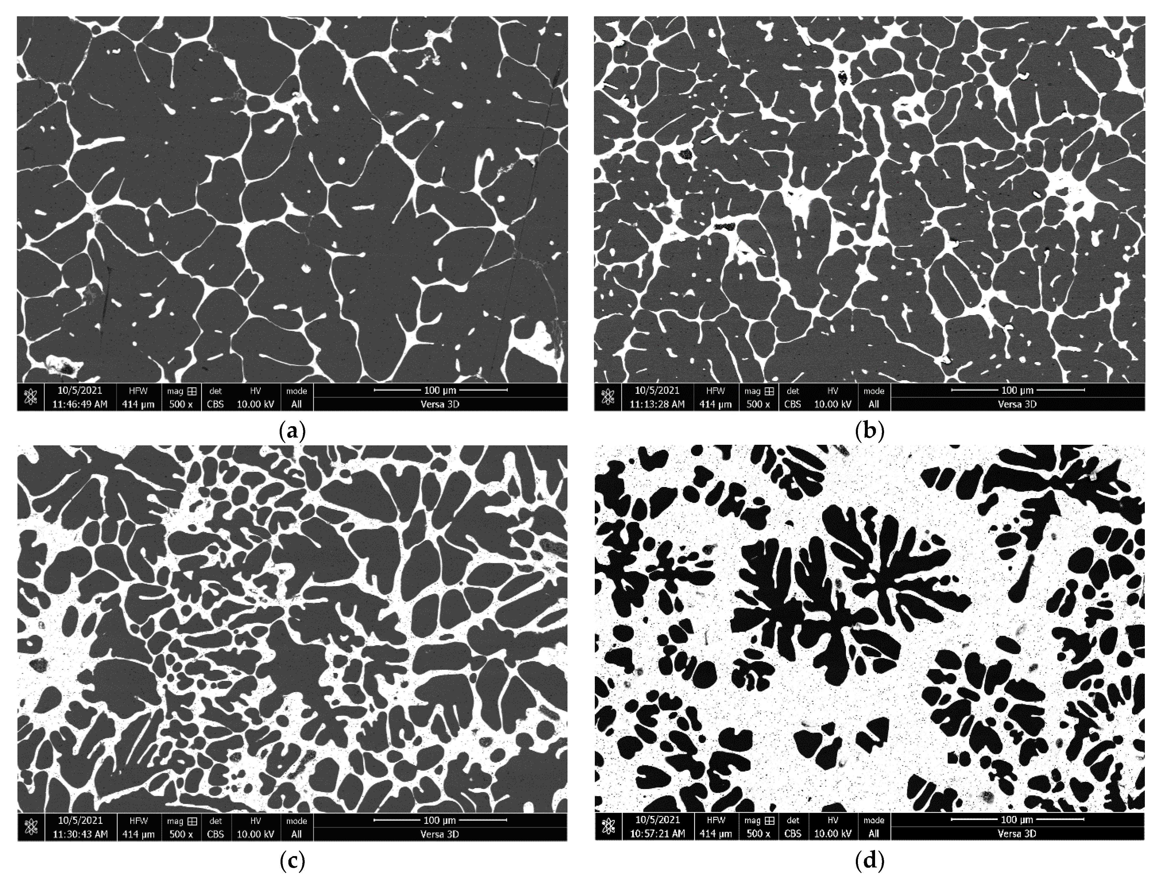
4.1. Microstructure of an Al-Sn Matrix Alloy

Figure 2 shows images of the microstructure of a matrix alloy with different tin contents. In the figures, tin looks lighter than aluminum and is located mainly along the boundaries of aluminum grains. As the tin content increases, the volume fraction of the aluminum grains decreases, the grains acquire a dendritic structure, and the proportion of the tin interlayer increases.

4.2. Conditional Yield Stress, Microhardness, Shear Modulus, and Young’s Modulus of the Matrix Alloy

Figure 3a depicts dependence of the microhardness and conditional yield stress of the matrix alloy on the tin content. An increase in the tin content leads to a monotonic decrease in the microhardness and conditional yield stress of the matrix alloy from 305 to 63 MPa and from 32 to 5 MPa, respectively.
As in the case of the parameters discussed above, with an increase in the tin content, Young’s modulus and the shear modulus of the matrix alloy decrease almost linearly from 65 to 52 GPa and from 24 to 20 GPa, respectively (Figure 3b).

4.3. Fracture Surfaces of A CF/Al-Sn Wire

Figure 4 shows fracture surfaces of a composite CF/Al-Sn wire with different tin content in the matrix alloy. The fracture surface of the tin-free composite wire appears to be almost flat. The photo demonstrates that some of the fibers collapsed outside the main fracture plane and were pulled out of the matrix. In this case, the average length of the pulled-out fiber part does not exceed 5 µm. With an increase in the tin content in the Al-Sn matrix alloy, the fracture surface of the composite becomes increasingly relief; the average length of the pulled-out fiber part also increases and reaches 42 μm at a tin content in the matrix alloy of 50 at.%.
Figure 5 shows deformation curves of a composite with a pure aluminum matrix and a matrix containing 50 at.% tin subjected to three-point bending in the stress–deflection axes. The curve corresponding to the composite with a pure aluminum matrix has the form characteristic of brittle materials; there is no plastic deformation region on this curve. The deformation curve of the composite with a matrix containing 50 at.% tin, on the contrary, has a pronounced quasi-plastic region. This region has a stepped shape typical of composites with weak boundaries.

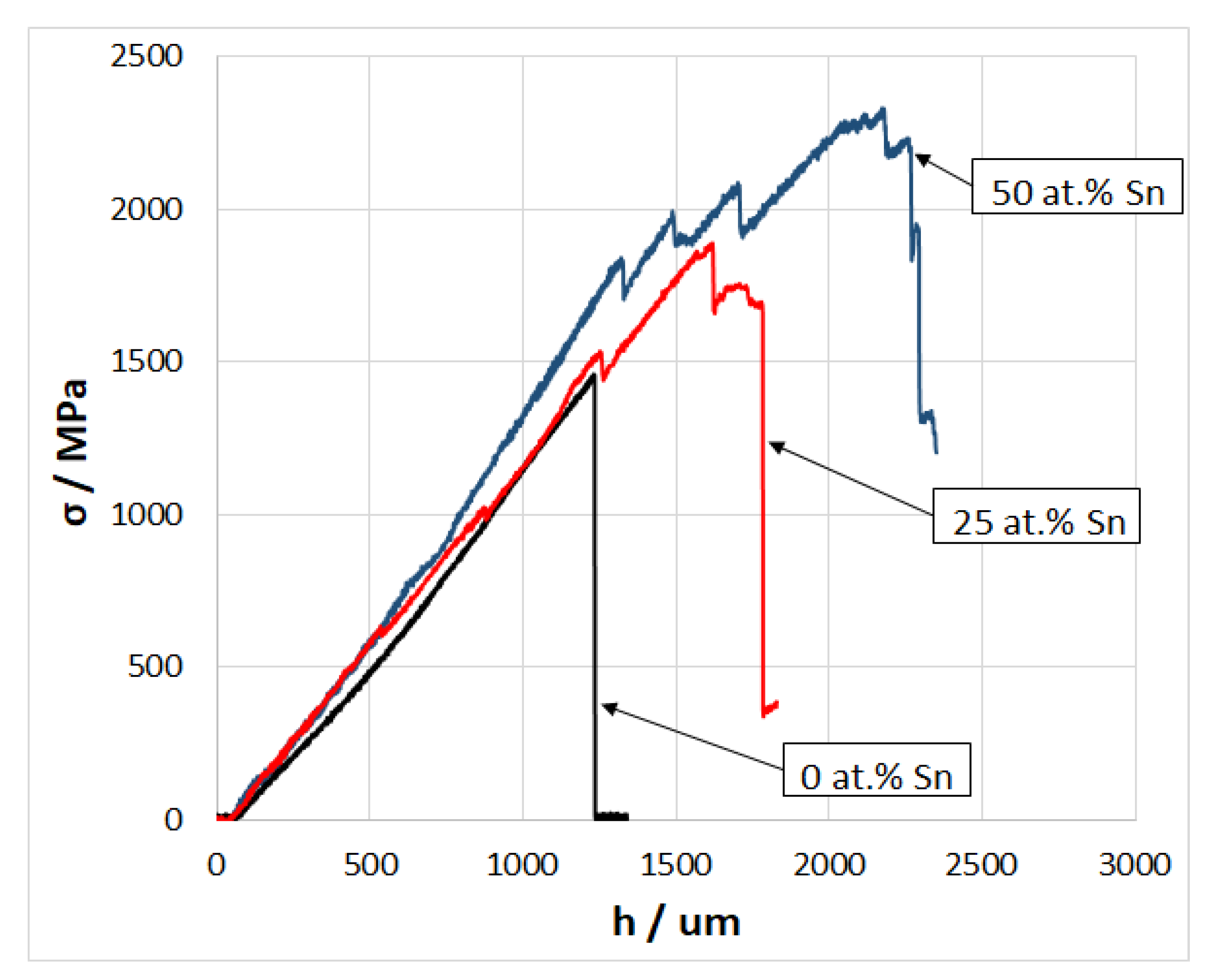
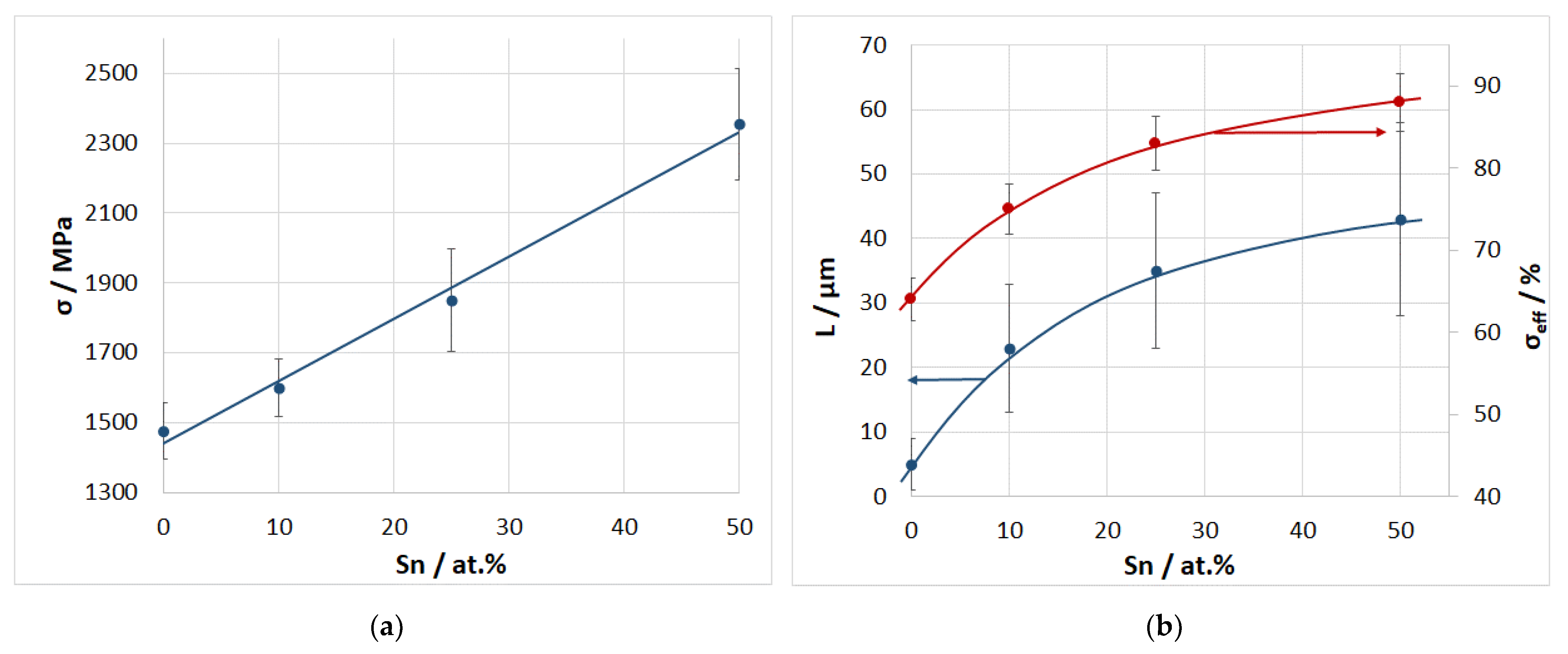
4.4. Strength of a CF/Al-Sn Wire and Effective Fiber Strength

The three-point bending strength of a composite wire is almost linear with the tin content (Figure 6a). With an increase in the tin content, the average strength increases from 1450 MPa for a composite without tin to 2365 MPa for a composite with 50 at.% tin in the matrix alloy.
In addition, Figure 6b depicts the dependence of the average effective fiber strength and the average length of the pulled-out part of the fibers at fracture on the tin content. With an increase in the tin content, the effective fiber strength increases from 65 to 89%; at the same time, the average length of the pulled-out part of the fibers increases from 5 to 42 μm. Note that both dependencies have a similar upward convex shape.

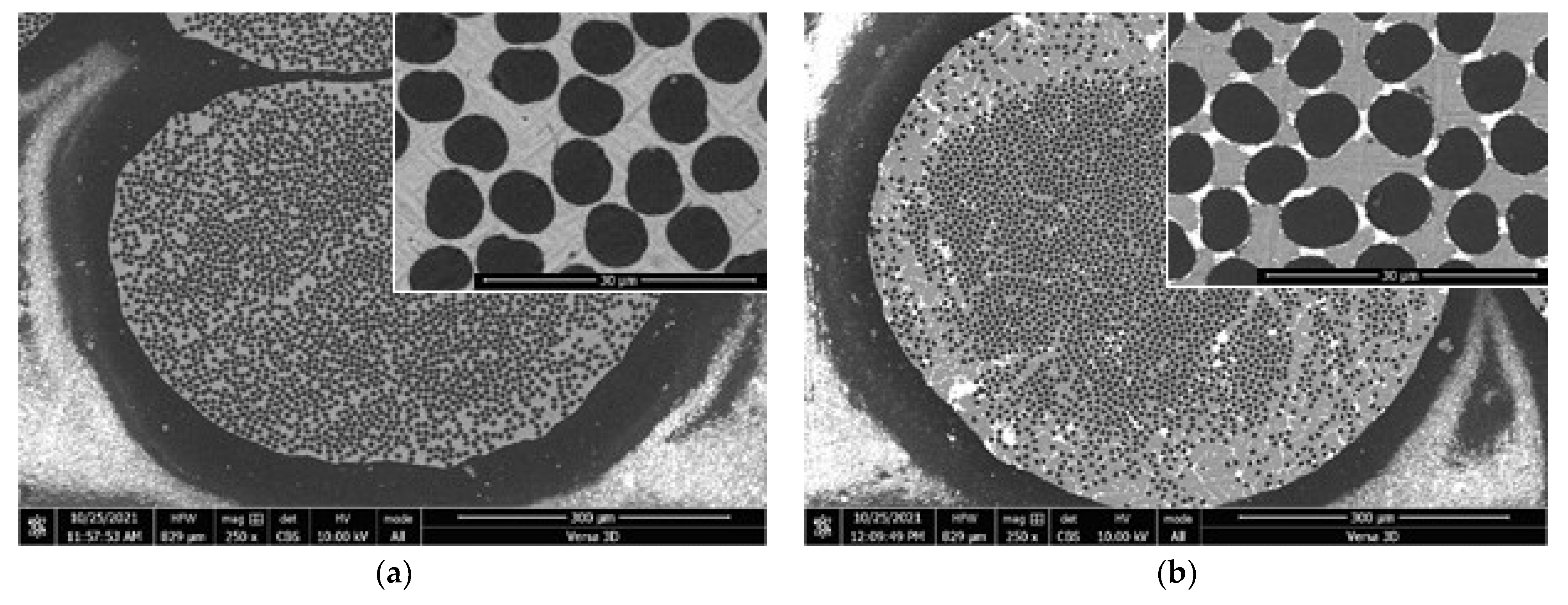
4.5. Microstructure of a CF/Al-Sn Wire

The microstructure of the composite CF/Al-Sn wire with different tin content in the matrix alloy is shown in Figure 7. When tin content in the matrix alloy is 10 at.%, the main volume of the matrix is occupied by aluminum, and tin is segregated between the fibers in the form of bridges, and most of the fiber surface is in contact with aluminum. As the tin content increases, the contact area between tin segregations and the fiber increases. In the composite structure, with tin content of 50 at.% one can distinguish fibers that almost do not have contact with aluminum.

5. Discussion

5.1. Matrix Alloy

The resulting matrix alloys have a structure characteristic of alloys of the Al-Sn system [11,12]. The change in mechanical properties depending on tin content has a monotonic, almost linear, character, which is most likely due to an almost complete absence of mutual solubility of aluminum and tin. In [13], the values of the yield point of Al-Sn alloys obtained by the method of directional crystallization with tin content up to 10 at.% are given. These values range from 35 to 45 MPa, depending on the tin content and crystallization conditions. Taking into account the absence of a predominant direction of crystallization in the alloys produced in this work, the results obtained are in good agreement with those mentioned.

5.2. Composite CF/Al-Sn-Wire

As mentioned in the Introduction, the mechanical properties of metal matrix composites are determined by the properties of the matrix, fiber, and the interface between them. However, the properties of a composite generally are not the sum of the properties of its components but are synergistic in nature [16]. Such a relationship between the properties of the composite and properties of initial components is likely to take place due to the chemical processes of interaction (or their absence) between the latter. For example, this was explicitly demonstrated in [17]. Apparently, a similar complex effect of tin influence is observed in the present work.
Apparently, the addition of tin to the aluminum matrix has a positive effect on the composite strength (Figure 6a). At the same time, an increase in the composite strength occurs due to an increase in the effective fiber strength (Figure 6b) because, with an increase in the tin content, the matrix strength decreases (Figure 3a). The effective fiber strength depends on many parameters, including the volume fraction of the fiber, strength, plasticity and elasticity of the matrix, and others [4]. All other conditions being the same, an increase in the effective strength can occur for several reasons. One of these is a decrease in the elastic modulus of the matrix, which contributes to a more even distribution of the load between the fibers. A decrease in the matrix strength can also explain an increase in the effective strength, which was shown in [6,7,8]. However, according to the authors, the greatest contribution to this is made by the formation of weak boundaries between the matrix and the fiber. With an increase in the tin content, the average length of the pulled-out fibers increases, which indicates a decrease in the strength of the bond between the matrix and the fiber. In this case, the bond strength is inversely proportional to the tin content, as evidenced by the dependence in Figure 6b. The chemical reaction between aluminum and carbon leads to the formation of a strong bond between the matrix and the fiber. Most likely, due to a decrease in the chemical activity of the matrix alloy, tin makes boundaries weaker because it is chemically inert to carbon. In addition, in the composite structure, tin is segregated in the gaps between the aluminum grains and the fiber (Figure 2), which also helps to reduce the matrix–fiber bond because tin has low strength.
The formation of weak boundaries between the matrix and the fiber leads to several consequences. First, it leads to an increase in the critical fiber length—the fiber segments carrying the load [4]. Thus, according to the Weibull distribution, the number of natural defects in the critical fiber length increases. This, in turn, leads to a decrease in the effective strength of the fiber and the composite as a whole [18].
In addition, weak boundaries between the matrix and the fiber prevent the propagation of main cracks and prevent early fracture of the composite. In this case, when a crack propagates, it must go around the fiber segments of a rather large critical length. This leads to the dissipation of elastic energy and restrains cracking. This effect is clearly seen from the fracture surface and the presence of a quasi-plastic region on the deformation curve (Figure 4 and Figure 5). In the case of a strong bond between the matrix and the fiber, the critical fiber length is so short that it leads to the propagation of the main crack (Figure 4a) and early brittle fracture of the composite. In the case of weak boundaries, on the contrary, the crack cannot propagate in one plane and is “forced” to change direction, and, as a result, it is restrained [4].
Thus, a decrease in the strength of the bond between the matrix and the fiber leads to a decrease in the composite strength, and, conversely, to its increase. A schematic representation of the dependence of the composite strength σ on the shear strength of the interface between the matrix and the fiber τ is shown in Figure 8.
The σc curve denotes the critical stress required for crack propagation in the composite, and the σ* curve denotes the theoretical strength of the composite that takes into account a decrease in the fiber strength with an increase in its critical length according to the Weibull distribution [18]. The intersection of these curves determines τcr, which is the value of the boundary shear strength at which the critical stress of crack propagation and the theoretical composite strength are equal. All other conditions being the same, this value is optimal for achieving the greatest strength of the composite material.
Apparently, the different tin content in the matrix of CF/Al-Sn composites obtained in this work provides a shear strength of the boundary greater than τcr, which, in turn, is expressed in the form of a monotonic increase in the composite strength (Figure 6a). Thus, the tin content of 50% is not an extreme point of the composite strength, all other conditions being the same.

6. Conclusions

  • The effect of tin content in the Al-Sn alloy in the range from 0 to 100 at.% on its mechanical properties was studied. An increase in the tin content leads to a monotonic decrease in the microhardness and conditional yield stress of the Al-Sn alloy from 305 to 63 MPa and from 32 to 5 MPa, respectively. In addition, Young’s modulus and the shear modulus of the Al-Sn alloy decrease from 65 to 52 GPa and from 24 to 20 GPa, respectively. The change in these mechanical properties is almost linear, which is most likely due to an almost complete absence of mutual solubility and interaction between aluminum and tin.
  • The effect of tin content in the Al-Sn matrix alloy in the range from 0 to 50 at.% on the strength of the CF/Al-Sn composite subjected to three-point bending was also investigated. Increasing tin content up to 50 at.% leads to a linear increase in the composite strength from 1450 to 2365 MPa, which is due to an increase in the effective fiber strength from 65 to 89%.
  • The addition of tin up to 50 at.% to the matrix alloy leads to the formation of weak boundaries between the matrix and the fiber. This is most likely due to the suppression of the chemical reaction between aluminum and carbon and the fact that, in the composite structure, tin is predominantly located in the spaces between the fiber and aluminum grains. An increase in the composite strength is accompanied by an increase in the average length of the fibers pulled out at the fracture surface.

Author Contributions

Conceptualization, S.G.; methodology, S.G., V.O., E.K.; investigation, T.A., V.O., E.K., B.A. and O.A.; writing—original draft preparation, S.G. and O.A.; writing—review and editing, S.G.; visualization, S.G.; supervision, S.G.; project administration, S.G.; funding acquisition, S.G. All authors have read and agreed to the published version of the manuscript.

Funding

This research was funded by the Russian Science Foundation, Grant No. 20-79-00004.

Institutional Review Board Statement

Not applicable.

Informed Consent Statement

Not applicable.

Data Availability Statement

The data presented in this study are available on request from the corresponding author.

Acknowledgments

The authors are grateful to Sergei Tikhonovich Mileiko, Nikolai Pavlivich Kobelev, Vladimir Vasilevich Astanin, Evgeniya Yurevna Postnova, Olga Feliksovna Shakhlevich, and Elena Yurevna Aksenova. The research part of the work was carried out at the Collective Use Center of ISSP RAS.

Conflicts of Interest

The authors declare no conflict of interest.

References

  1. Vidal-Sétif, M.; Lancin, M.; Marhic, C.; Valle, R.; Raviart, J.-L.; Daux, J.-C.; Rabinovitch, M. On the role of brittle interfacial phases on the mechanical properties of carbon fibre reinforced Al-based matrix composites. Mater. Sci. Eng. A 1999, 272, 321–333. [Google Scholar] [CrossRef]
  2. Yu, J.K.; Li, H.L.; Shang, B.L. A functionally gradient coating on carbon fibre for C/Al composites. J. Mater. Sci. 1994, 29, 2641–2647. [Google Scholar] [CrossRef]
  3. Matsunaga, T.; Matsuda, K.; Hatayama, T.; Shinozaki, K.; Yoshida, M. Fabrication of continuous carbon fiber-reinforced aluminum–magnesium alloy composite wires using ultrasonic infiltration method. Compos. Part A Appl. Sci. Manuf. 2007, 38, 1902–1911. [Google Scholar] [CrossRef]
  4. Mileiko, S.T. Metal and Ceramic Based Composites; Elsevier: Amsterdam, The Netherlands, 1997; ISBN 9780444828149. [Google Scholar]
  5. Sobczak, N.; Kudyba, A.; Siewiorek, A.; Homa, M.; Nowak, R.; Ruzda, G.; Sobczak, J.J.; Turalska, P.; Tchorz, A.; Andrzej, G.; et al. Textile Reinforced Carbon Fibre/Aluminium Matrix Composites for Lightweight Applications; Gude, M., Boczkowska, A., Eds.; Foundry Research Institute: Krakow, Poland, 2014; ISBN 9788388770975. [Google Scholar]
  6. Galyshev, S. On the Strength of the CF/Al-Wire Depending on the Fabrication Process Parameters: Melt Temperature, Time, Ultrasonic Power, and Thickness of Carbon Fiber Coating. Metals 2021, 11, 1006. [Google Scholar] [CrossRef]
  7. Deve, H.E.; McCullough, C. Continuous-fiber reinforced composites: A new generation. JOMA 1995, 47, 33–37. [Google Scholar] [CrossRef]
  8. Du, Z.-Z.; McMeeking, R.M. Control of strength anisotropy of metal matrix fiber composites. J. Comput.-Aided Mater. Des. 1994, 1, 243–264. [Google Scholar] [CrossRef]
  9. Oden, L.L.; Gokcen, N.A. Sn-C and Al-Sn-C phase diagrams and thermodynamic properties of C in the alloys: 1550 °C to 2300 °C. Metall. Trans. B 1993, 24, 53–58. [Google Scholar] [CrossRef]
  10. McAlister, A.J.; Kahan, D.J. The Al−Sn (Aluminum-Tin) System. Bull. Alloy Phase Diagr. 1983, 4, 410–414. [Google Scholar] [CrossRef]
  11. Son, K.S.; Park, T.E.; Kim, J.S.; Kang, S.M.; Kim, T.H.; Kim, D. Microstructural Control of Al-Sn Alloy with Addition of Cu and Si. Korean J. Met. Mater. 2010, 48, 248–255. [Google Scholar] [CrossRef] [Green Version]
  12. Chikova, O.A.; Konstantinov, A.N.; Shishkina, E.V.; Chezganov, D.S. Influence of the microheterogeneity and crystallization conditions of the Al-50% Sn alloy on the mechanical properties of phase components of the ingot. Russ. J. Non-Ferr. Met. 2014, 55, 505–508. [Google Scholar] [CrossRef]
  13. Cruz, K.S.; Meza, E.S.; Fernandes, F.A.P.; Quaresma, J.M.V.; Casteletti, L.C.; Garcia, A. Dendritic Arm Spacing Affecting Mechanical Properties and Wear Behavior of Al-Sn and Al-Si Alloys Directionally Solidified under Unsteady-State Conditions. Metall. Mater. Trans. A 2010, 41, 972–984. [Google Scholar] [CrossRef]
  14. Galyshev, S.; Gomzin, A.; Gallyamova, R.; Khodos, I.; Musin, F. On the liquid-phase technology of carbon fiber/aluminum matrix composites. Int. J. Miner. Metall. Mater. 2019, 26, 1578–1584. [Google Scholar] [CrossRef]
  15. Kobelev, N.P.; Nikolaev, R.K.; Soifer, Y.M.; Khasanov, S.S. Elastic modules of monocrystalline C60. Solid State Phys. 1998, 40, 173. (In Russian) [Google Scholar] [CrossRef]
  16. Mileiko, S.T. Synergy in composites. Compos. Nanostruct. 2015, 7, 191–206. [Google Scholar]
  17. Mileiko, S.T.; Sarkissyan, N.S.; Kolchin, A.A.; Kiiko, V.M. Oxide fibres in a nickel-base matrix—Do they degrade or become stronger? Proc. Inst. Mech. Eng. Part L J. Mater. Des. Appl. 2004, 218, 193–199. [Google Scholar] [CrossRef]
  18. Curtin, W.A. Ultimate strengths of fibre-reinforced ceramics and metals. Composites 1993, 24, 98–102. [Google Scholar] [CrossRef]
Figure 1. Scheme for obtaining a CF/Al-Sn-wire.
Metals 11 02057 g001
Figure 2. Microstructure of an Al-Sn matrix alloy with tin content from 5 to 50 at.%: (a) 5% Sn, (b) 10% Sn, (c) 25% Sn, (d) 50% Sn.
Metals 11 02057 g002
Figure 3. Dependence of microhardness, conditional yield stress (a) and Young’s modulus and shear modulus (b) of the matrix Al-Sn alloy on the tin content.
Metals 11 02057 g003
Figure 4. Fracture surfaces of a CF/Al-Sn composite with tin content from 0 to 50 at.%: (a) 0% Sn, (b) 10% Sn, (c) 25% Sn, (d) 50% Sn.
Metals 11 02057 g004aMetals 11 02057 g004b
Figure 5. Curves of deformation of a CF/Al-Sn composite with tin content in the matrix of 0 and 50 at.%.
Metals 11 02057 g005
Figure 6. Dependence of the strength of a composite CF/Al-Sn wire subjected to three-point bending (a), effective fiber strength and length of the pulled-out part of the fiber at fracture (b) on the tin content.
Metals 11 02057 g006
Figure 7. Microstructure of a CF/Al-Sn composite with tin content from 0 to 50 at.%: (a) 0% Sn, (b) 10% Sn, (c) 25% Sn, (d) 50% Sn.
Metals 11 02057 g007aMetals 11 02057 g007b
Figure 8. Schematic representation of the dependence of the composite strength σ on the shear strength of the interface between the matrix and the fiber τ.
Metals 11 02057 g008
Publisher’s Note: MDPI stays neutral with regard to jurisdictional claims in published maps and institutional affiliations.

