
The Casting Rate Impact on the Microstructure in Al–Mg–Si Alloy with Silicon Excess and Small Zr, Sc Additives


 , ,
, ,
Abstract
:1. Introduction
2. Test Methods
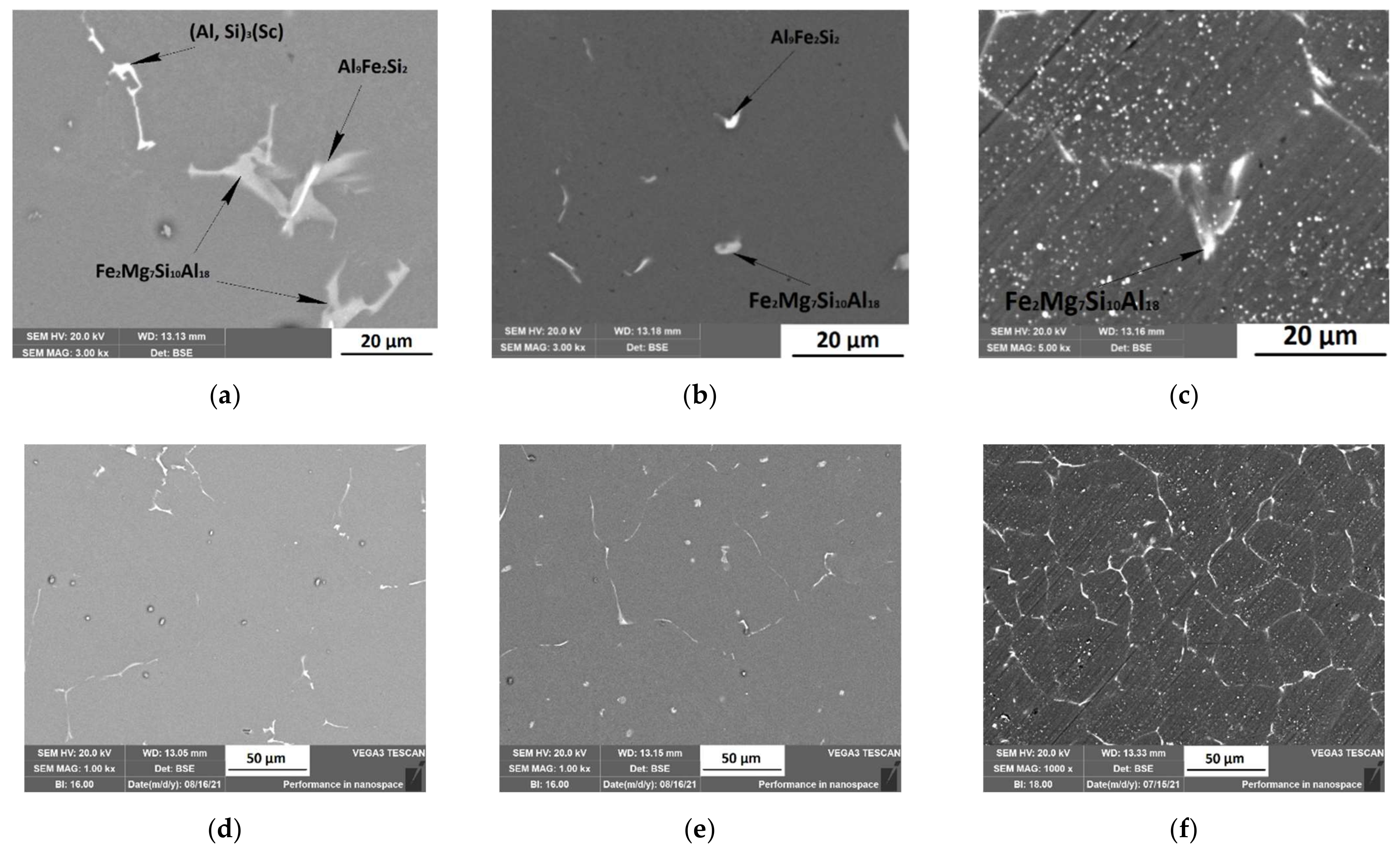
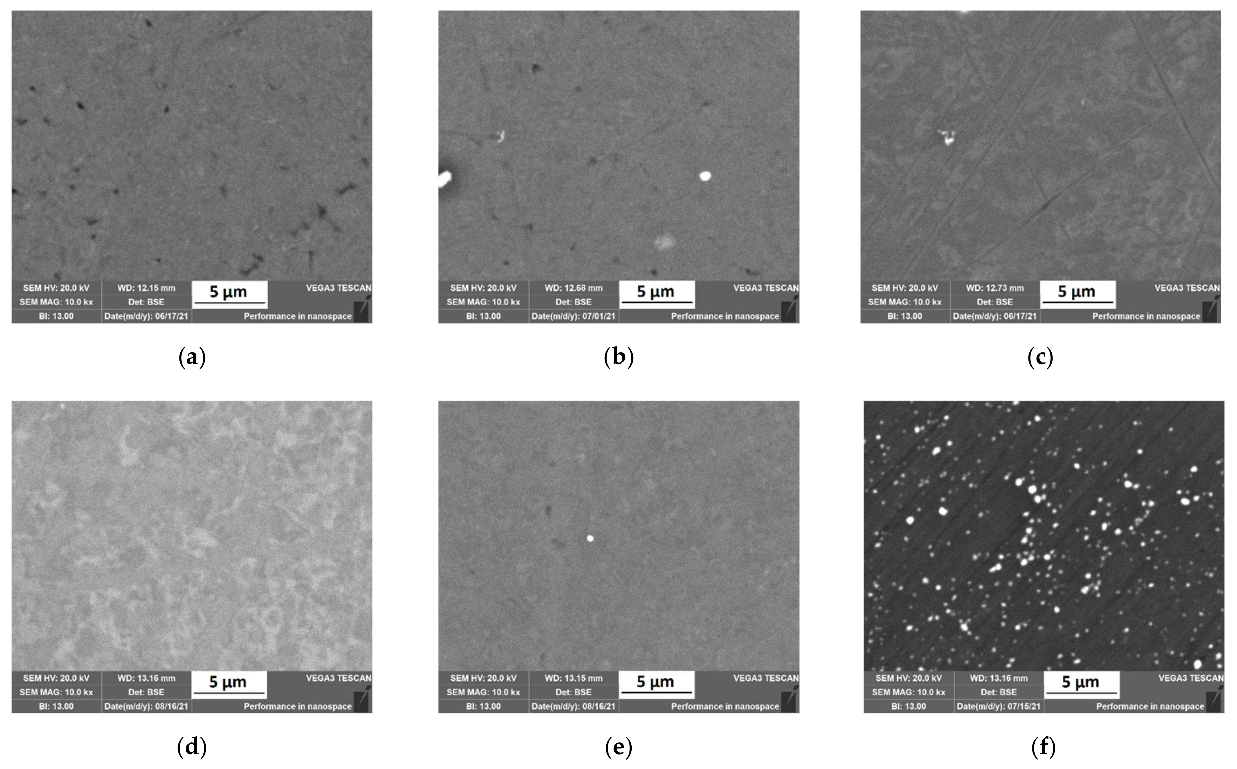
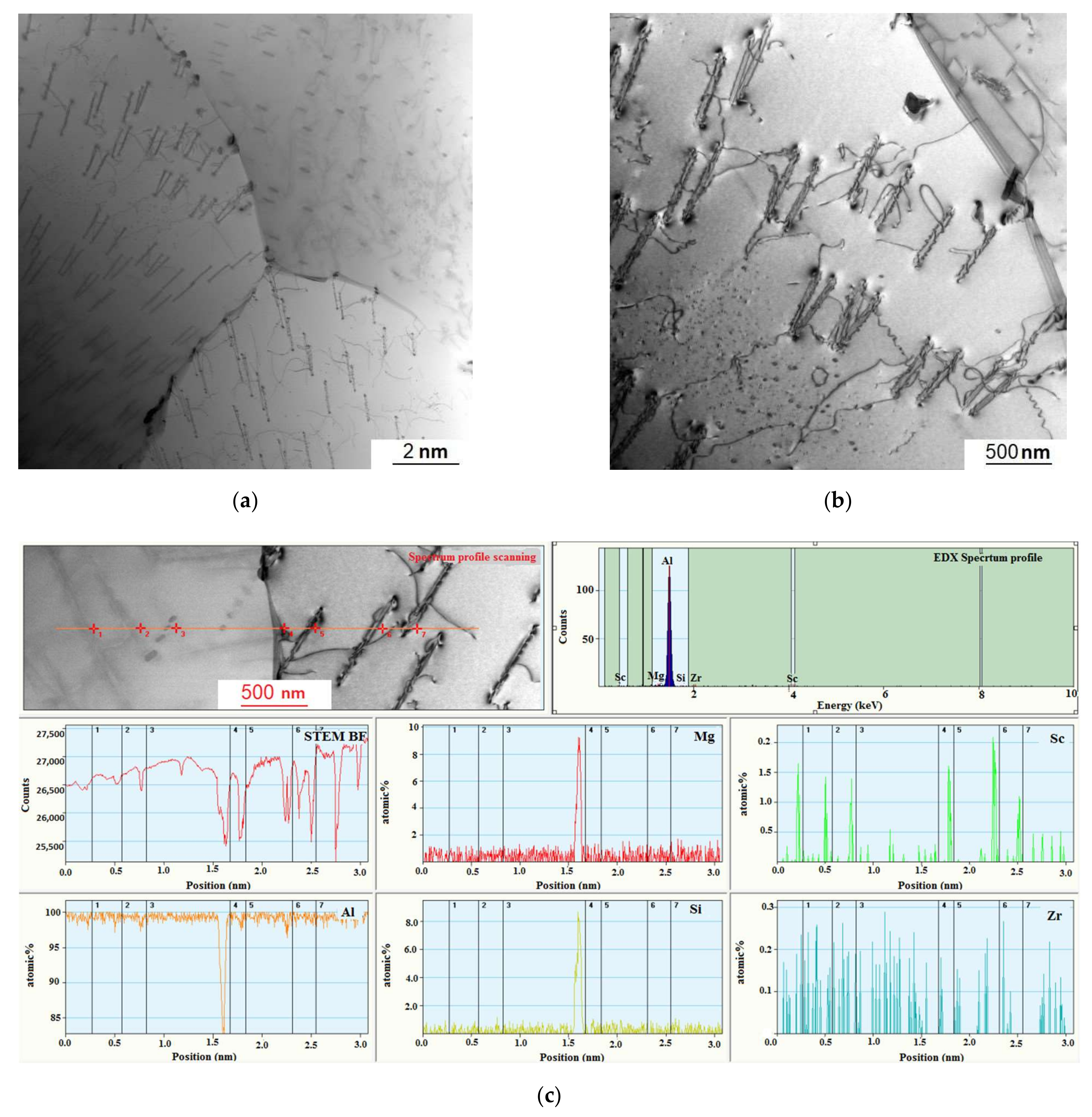
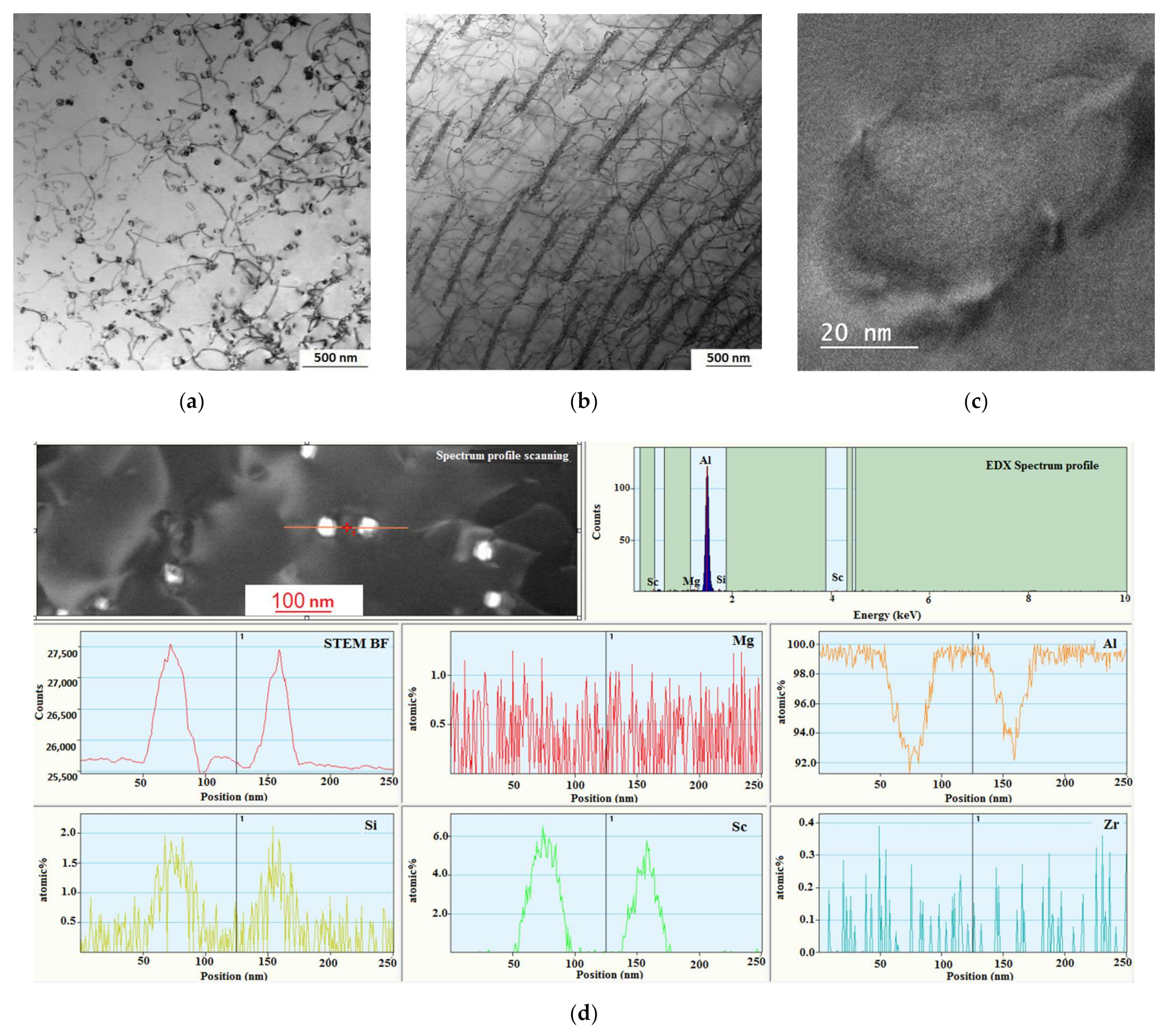
3. Results
4. Conclusions
Author Contributions
Funding
Data Availability Statement
Conflicts of Interest
References
- Chausov, M.; Pylypenko, A.; Maruschak, P.; Menou, A. Phenomenological Models and Peculiarities of Evaluating Fatigue Life of Aluminum Alloys Subjected to Dynamic Non-Equilibrium Processes. Metals 2021, 11, 1625. [Google Scholar] [CrossRef]
- Chausov, M.; Brezinova, J.; Zasimchuk, E.; Maruschak, P.; Khyzhun, O.; Pylypenko, A.; Bazarnik, P.; Brezina, J. Effect of Structure Self-Organization of Aluminum Alloy D16ChATW under Impact-Oscillatory Loading on Its Fatigue Life. J. Mater. Eng. Perform. 2021, 30, 6235–6242. [Google Scholar] [CrossRef]
- Alattar, A.L.; Bazhin, V.Y. Al–Cu–B 4 C Composite Materials for the Production of High-Strength Billets. Metallurgist 2020, 5, 566–573. [Google Scholar] [CrossRef]
- Kosov, Y.I.; Bazhin, V.Y. Synthesis of an aluminum–erbium master alloy from chloride–fluoride melts. Russ. Metall. 2018, 2, 139–148. [Google Scholar] [CrossRef]
- Belov, N.A.; Alabin, A.; Sannikov, A.; Deev, V.B. Primary crystallization in the Al-Fe-Mn-Ni-Si system as applied to casting alloys based on aluminum-nickel eutectic. Russ. J. Non-Ferr. Met. 2014, 55, 356–364. [Google Scholar] [CrossRef]
- Deev, V.B.; Selyanin, I.F.; Ponomareva, K.V.; Yudin, A.S.; Tsetsorina, S.A. Fast cooling of aluminum alloys in casting with a gasifying core. Steel Transl. 2014, 44, 253–254. [Google Scholar] [CrossRef]
- Du, H.; Zhang, S.; Zhang, B.; Tao, X.; Yao, Z.; Belov, N.; van der Zwaag, S.; Liu, Z. Ca-modified Al–Mg–Sc alloy with high strength at elevated temperatures due to a hierarchical microstructure. J. Mater. Sci. 2021, 56, 16145–16157. [Google Scholar] [CrossRef]
- Belov, N.; Akopyan, T.; Korotkova, N.; Murashkin, M.; Timofeev, V.; Fortuna, A. Structure and Properties of Ca and Zr Containing Heat Resistant Wire Aluminum Alloy Manufactured by Electromagnetic Casting. Metals 2021, 11, 236. [Google Scholar] [CrossRef]
- Kolobnev, N.I.; Ber, L.B.; Khokhlatova, L.B.; Ryabov, D.K. Structure, properties and application of the Al-Mg-Si-(Cu) system alloys. Metall. Heat Treat. Met. 2011, 9, 40–45. [Google Scholar] [CrossRef]
- Hirsch, J. Aluminium in Innovative Light-Weight Car Design. Mater. Trans. 2011, 52, 818–824. [Google Scholar] [CrossRef] [Green Version]
- Polmear, I. Light Alloys: From Traditional Alloys to Nanocrystals; Elsevier: Amsterdam, The Netherlands, 2005. [Google Scholar]
- Kharakterova, M.L.; Eskin, D.G.; Toropova, L.S. Precipitation hardening in ternary alloys of the Al Sc Cu and Al Sc Si systems. Acta Metall. Mater. 1994, 7, 2285–2290. [Google Scholar] [CrossRef]
- Zakharov, V.V. Effect of Scandium on the Structure and Properties of Aluminum Alloys. Met. Sci. Heat Treat. 2003, 45, 246–253. [Google Scholar] [CrossRef]
- Mousavi, M.; Cross, C. Effect of scandium and titanium–boron on grain refinement and hot cracking of aluminium alloy 7108. Sci. Technol. Weld. Join. 1999, 4, 381–388. [Google Scholar] [CrossRef]
- Kim, J.H.; Kim, J.H.; Yeom, J.T.; Lee, D.G.; Lim, S.G.; Park, N.K. Effect of scandium content on the hot extrusion of Al–Zn–Mg–(Sc) alloy. J. Mater. Process. Technol. 2007, 187, 635–639. [Google Scholar] [CrossRef]
- Tsao, C.S.; Chen, C.Y.; Jeng, U.S.; Kuo, T.Y. Precipitation kinetics and transformation of metastable phases in Al–Mg–Si alloys. Acta Mater. 2006, 17, 4621–4631. [Google Scholar] [CrossRef]
- Niranjani, V.L.; Kumar, K.H.; Sarma, V.S. Development of high strength Al–Mg–Si AA6061 alloy through cold rolling and ageing. Mater. Sci. Eng. 2009, 515, 169–174. [Google Scholar] [CrossRef]
- Lodgaard, L.; Ryum, N. Precipitation of dispersoids containing Mn and/or Cr in Al–Mg–Si alloys. Mater. Sci. Eng. 2000, 283, 144–152. [Google Scholar] [CrossRef]
- Esmaeili, S.; Wang, X.; Lloyd, D.J.; Poole, W.J. On the precipitation-hardening behavior of the Al-Mg-Si-Cu alloy AA6111. Metall. Mater. Trans. A 2003, 34, 751–763. [Google Scholar] [CrossRef]
- Van Huis, M.; Chen, J.; Sluiter, M.; Zandbergen, H. Phase stability and structural features of matrix-embedded hardening precipitates in Al–Mg–Si alloys in the early stages of evolution. Acta Mater. 2007, 55, 2183–2199. [Google Scholar] [CrossRef]
- Marquis, E.; Seidman, D. Nanoscale structural evolution of Al3Sc precipitates in Al (Sc) alloys. Acta Mater. 2001, 49, 1909–1919. [Google Scholar] [CrossRef] [Green Version]
- Davydov, V.G.; Rostova, T.D.; Zakharov, V.V.; Filatov, Y.A.; Yelagin, V.I. Scientific principles of making an alloying addition of scandium to aluminium alloys. Mater. Sci. Eng. 2000, 280, 30–36. [Google Scholar] [CrossRef]
- Singh, V.; Prasad, K.S.; Gokhale, A.A. Effect of minor Sc additions on structure, age hardening and tensile properties of aluminium alloy AA8090 plate. Scr. Mater. 2004, 50, 903–908. [Google Scholar] [CrossRef]
- Yu, K.; Li, W.; Li, S.; Zhao, J. Mechanical properties and microstructure of aluminum alloy 2618 with Al3(Sc, Zr) phases. Mater. Sci. Eng. A 2004, 368, 88–93. [Google Scholar] [CrossRef]
- Dev, S.; Stuart, A.A.; Kumaar, R.R.D.; Murty, B.S.; Rao, K.P. Effect of scandium additions on microstructure and mechanical properties of Al–Zn–Mg alloy welds. Mater. Sci. Eng. 2007, 467, 132–138. [Google Scholar] [CrossRef]
- Norman, A.; Hyde, K.; Costello, F.; Thompson, S.; Birley, S.; Prangnell, P. Examination of the effect of Sc on 2000 and 7000 series aluminium alloy castings: For improvements in fusion welding. Mater. Sci. Eng. A 2003, 354, 188–198. [Google Scholar] [CrossRef]
- Fuller, C.B.; Seidman, D.N.; Dunand, D.C. Creep properties of coarse-grained Al (Sc) alloys at 300 °C. Scr. Mater. 1999, 40, 691–696. [Google Scholar] [CrossRef]
- Lee, S.; Utsunomiya, A.; Akamatsu, H.; Neishi, K.; Furukawa, M.; Horita, Z.; Langdon, T. Influence of scandium and zirconium on grain stability and superplastic ductilities in ultrafine-grained Al–Mg alloys. Acta Mater. 2002, 50, 553–564. [Google Scholar] [CrossRef]
- Tolley, A.; Radmilovic, V.; Dahmen, U. Segregation in Al3 (Sc, Zr) precipitates in Al–Sc–Zr alloys. Scr. Mater. 2005, 7, 621–625. [Google Scholar] [CrossRef]
- Iwamura, S.; Miura, Y. Loss in coherency and coarsening behavior of Al3Sc precipitates. Acta Mater. 2004, 52, 591–600. [Google Scholar] [CrossRef]
- Bazhin, V.Y.; Kosov, Y.I.; Lobacheva, O.L.; Dzhevaga, N. Synthesis of aluminum-based scandium–yttrium master alloys. Russ. Metall. (Met.) 2015, 2015, 516–520. [Google Scholar] [CrossRef]
- Davydov, V.G.; Elagin, V.I.; Zakharov, V.V.; Rostoval, D. Alloying aluminum alloys with scandium and zirconium additives. Met. Sci. Heat Treat. 1996, 8, 347–352. [Google Scholar] [CrossRef]
- Tyvanchuk, A.T.; Yanson, T.I.; Kotur, B.Y.; Zarechnyuk, O.S.; Kharakterova, M.L. Isothermal section of Sc-Al-Si system at 770 K. Izv. Akad. Nauk. SSSR-Met. 1988, 20, 187–188. [Google Scholar]
- Rokhlin, L.L.; Bochvar, N.R.; Rybal’Chenko, O.V.; Tarytina, I.E.; Sukhanov, A.V. Phase equilibria in aluminum-rich Al-Sc-Si alloys during solidification. Russ. Metall. (Met.) 2012, 2012, 606–611. [Google Scholar] [CrossRef]
- Babaniaris, S.; Ramajayam, M.; Jiang, L.; Langan, T.; Dorin, T. Developing an Optimized Homogenization Process for Sc and Zr Containing Al-Mg-Si Alloys. In Light Metals; Springer: Cham, Switzerland, 2019; pp. 1445–1453. [Google Scholar] [CrossRef] [Green Version]
- Babaniaris, S.; Ramajayam, M.; Jiang, L.; Langan, T.; Dorin, T. Tailored precipitation route for the effective utilisation of Sc and Zr in an Al-Mg-Si alloy. Materialia 2020, 10, 100656. [Google Scholar] [CrossRef]
- Porter, D.A.; Easterling, K.E. Phase Transformations in Metals and Alloys (Revised Reprint); CRC Press: Boca Raton, FL, USA, 2009. [Google Scholar] [CrossRef]
- Wang, F.; Qiu, D.; Liu, Z.; Taylor, J.A.; Easton, M.; Zhang, M.-X. The grain refinement mechanism of cast aluminium by zirconium. Acta Mater. 2013, 61, 5636–5645. [Google Scholar] [CrossRef]
- Norman, A.; Prangnell, P.; McEwen, R. The solidification behaviour of dilute aluminium–scandium alloys. Acta Mater. 1998, 46, 5715–5732. [Google Scholar] [CrossRef]
- Blake, N.; Hopkins, M.A. Constitution and age hardening of Al-Sc alloys. J. Mater. Sci. 1985, 20, 2861–2867. [Google Scholar] [CrossRef]
- Yashin, V.V.; Aryshensky, E.V.; Latushkin, I.A.; Stozharov, D.A. Study of kinetics of the supersaturated solid solution de-composition in alloys of the Al-Mg system with transition elements addition. Tsvetnye Met. 2020, 11, 77–84. [Google Scholar]


| Alloy | Steel Chill Mold | Copper Chill Mold | Conical Chill Mold |
|---|---|---|---|
| Al0.3Mg1Si | + | + | + |
| Al0.3Mg1Si0.3Sc0.15Zr | + | + | + |
| Type of the Casting Mold | Cooling Rate, °C/s | ||
|---|---|---|---|
| during Crystallization | after Crystallization Until Complete Cooling | All-Time Average | |
| Steel chill mold | 2 | 0.7 | 0.72 |
| Copper chill mold | 10 | 3.2 | 3.5 |
| Copper chill mold with circular section | 30 | 8.1 | 8.6 |
Publisher’s Note: MDPI stays neutral with regard to jurisdictional claims in published maps and institutional affiliations. |
© 2021 by the authors. Licensee MDPI, Basel, Switzerland. This article is an open access article distributed under the terms and conditions of the Creative Commons Attribution (CC BY) license (https://creativecommons.org/licenses/by/4.0/).
Share and Cite
Aryshenskii, E.; Lapshov, M.; Konovalov, S.; Hirsch, J.; Aryshenskii, V.; Sbitneva, S. The Casting Rate Impact on the Microstructure in Al–Mg–Si Alloy with Silicon Excess and Small Zr, Sc Additives. Metals 2021, 11, 2056. https://doi.org/10.3390/met11122056
Aryshenskii E, Lapshov M, Konovalov S, Hirsch J, Aryshenskii V, Sbitneva S. The Casting Rate Impact on the Microstructure in Al–Mg–Si Alloy with Silicon Excess and Small Zr, Sc Additives. Metals. 2021; 11(12):2056. https://doi.org/10.3390/met11122056
Chicago/Turabian StyleAryshenskii, Evgenii, Maksim Lapshov, Sergey Konovalov, Jurgen Hirsch, Vladimir Aryshenskii, and Svetlana Sbitneva. 2021. "The Casting Rate Impact on the Microstructure in Al–Mg–Si Alloy with Silicon Excess and Small Zr, Sc Additives" Metals 11, no. 12: 2056. https://doi.org/10.3390/met11122056