Article

Numerical Model Simulation of the Double-Roll Rotary Forging of Large Diameter Thin-Walled Disk

1
School of Materials Science and Engineering, Wuhan University of Technology, Wuhan 430070, China
2
School of Materials Science and Engineering, Industrial Research Institute, Wuhan University of Technology, Suizhou 441399, China
*
Author to whom correspondence should be addressed.
Metals 2021, 11(11), 1767; https://doi.org/10.3390/met11111767
Submission received: 8 October 2021 / Revised: 27 October 2021 / Accepted: 29 October 2021 / Published: 3 November 2021
(This article belongs to the Special Issue Sheet Metal Forming)

Abstract

:
Double-roll rotary forging is an emerging plastic forming technology based on rotary forging. Owing to the advantages of being labor-saving, a small eccentric load, low noise and vibration, good uniformity, high surface quality, and material saving, it is very promising for the fabrication of large diameter thin-walled disks. To date, little relevant research on the double-roll rotary forging technology of large diameter thin-walled metal disks has been reported, and the deformation characteristic and the influence of three key parameters on the double-roll rotary forging process remain uninvestigated. Herein, a reasonable 3D rigid-plastic numerical model of the double-roll rotary forging of a disk workpiece is established under the Deform software environment. Based on the valid 3D numerical model, the deformation mechanism, and the effective laws of three key parameters (feed rate v of the lower die, rotational speed n of the upper die, and the initial temperature T of the disk workpiece) on the metal flow and force and power parameters in the double-roll rotary forging process have been explored. The research results provide valuable guidelines for a better understanding of double-roll rotary forging for the fabrication of large diameter thin-walled disks.

1. Introduction

Large diameter and thin-walled metal discs are key components in nuclear power, aerospace, deep-sea exploration, and other industrial fields. Conventional processes for manufacturing large diameter and thin-walled metal disks comprise hot die forging and hammer forging, or isothermal forging [1,2,3]. As the size of the large diameter and thin-walled metal discs workpiece increases, the huge forging tonnage makes it impossible to manufacture the large diameter and thin-walled metal discs by forging. Hot rolling technology can reduce forming load and manufacture thin-walled metal plates [4,5,6]. However, the formed shapes of hot rolling require extensive machining to produce the final disc workpiece, this disrupts the metal flow and affects the performance of the disc workpiece. To prepare large diameter and thin-walled metal discs with better performance, rotary forging technology has been introduced due to the advantage of being labor-saving, its low noise and vibration, good uniformity, material saving, and metal streamline integrity.
Up to now, many scholars have studied the rotary forging process, the early research mainly concentrated on the distribution of energy and load [7,8], studying the metal flow [9,10], and analyzing the forming defects [11,12], which established the fundamental laws for the cylindrical workpiece forming. However, the forming characteristics and mechanism of rotary forging were not studied fully until the emergence of finite element methods. Liu and Yuan et al. [13,14,15] first used a 3D rigid-plastic finite element software, Deform, to reveal the forming mechanism of the pins and cylinder workpiece of cold rotary forging, but elastic deformation of the workpiece of cold rotary forging was not considered. Han [16,17,18] developed 3D elastoplastic FE software ABAQUS to improve the calculation accuracy of cylindrical and the rings of cold rotary forging. Apart from these studies focusing on the cold rotary forging process, Mandal and Zheng et al. [19,20,21,22,23,24] studied hot rotary forging by investigating the forming characteristics of cylinder and flanges, which is more favorable for less deformable materials.
The above research associated with the rotary forging process takes advantage of a single roll with the inclination angle below 6° of the upper die, and the contact area between the upper die and the disk workpiece is located on one side of the cylinder workpiece, which thus makes an eccentric load appear during the forming process. As the size of the cylinder workpiece grows, the eccentric load will become more significant, which is detrimental for the large size cylinder workpiece forging process. In addition, when the cylinder workpiece is very thin, it will warp easily on the side that is not rolled. Therefore, rotary forging technology is unavailable to form large diameter thin-walled disk workpieces. To address this problem, we [25] proposed for the first time a double-roll rotary forging method and designed the double-roll forging machine, which transformed the single roll into two symmetrical rolls along the central axis of the two main shafts. This technology remarkably eliminated the influence of the eccentric load of the workpiece during the forming process, and broke through the forming size limit of the rotary forging process, making it possible to form a large diameter thin-wall disk workpiece. Up to now, there have been few types of research on the double-roll rotary forging of large diameter thin-wall disk workpieces, and the deformation characteristic and influence laws of the three key parameters of large diameter thin-wall disk workpieces remain unclear; thus, it is difficult to select the proper processing parameters and control the forming process.
Herein, this work establishes a reasonable 3D rigid-plastic numerical model of the double-roll rotary forging of a disk workpiece under the Deform software environment. Based on the valid 3D numerical model, the deformation characteristic and the influence of three key parameters (feed rate v of the lower die, rotational speed n of the upper die, the initial temperature T of the disk workpiece) on metal flow and the force and power parameters in the double-roll rotary forging process have been studied. The research results provide valuable guidelines for optimizing and precisely controlling the double-roll rotary forging process.

2. Three-Dimensional Numerical Modeling of Double-Roll Rotary Forging

2.1. Working Principle of Double-Roll Rotary Forging

The working principle of double-roll rotary forging and the integral forming of large diameter thin-walled metal disk is shown in Figure 1: The double rollers continuously rotate around the central axis of the main shaft of the equipment, and the lower die simultaneously feeds the disk workpiece upwards. When the disk workpiece is in contact with the double rollers, the double rollers rotate around their spinning axis under the actuation of friction force between the disk workpiece and the rollers to realize the integral forming of the large diameter thin-walled metal disk. As soon as the disk workpiece is formed to the target height, the lower die stops feeding upwards, while the double rollers continue to rotate to flatten the upper surface of the disk workpiece.

2.2. Three-Dimensional Numerical Model and Boundary Conditions

The characteristics of highly nonlinear, local contact, large plastic deformation, and the complex dynamic plastic flow process from the axial, radial, and circumferential sections exist during hot double-roll rotary forging, which better reveal the plastic deformation mechanism and stress, strain, and other characteristics of the workpiece. Therefore, Deform-3D software (v11.0, Science Forming Technology Corporation, Columbus, OH, USA) was used to establish the numerical model of the integral forming of the large diameter thin-walled metal disk double-roller rotary forging. As shown in Figure 2, both the upper die and the lower die are set as a rigid body, and the material of the disk workpiece is AISI-1020, which is set as a plastic body. The stress–strain relationship of AISI-1020 comes from the material library in Deform-3D software, as shown in Figure 3. The mechanical properties of the AISI-1020 material are shown in Table 1. Because the friction between the upper die and the workpiece is rolling friction, we chose the friction coefficient of the upper die and workpiece to be 0.1, as shown in Table 2. The contact pressure between the die and the workpiece continues to increase during the forming process, which will increase the thermal conductivity coefficient between the die and the workpiece. Therefore, we choose the thermal conductivity coefficient between the die and the workpiece to be 15 (kW/m2·°C), as shown in Table 2.
Due to the gap between the two rolls of the upper die of the double-roll rotary forging equipment, as shown in Figure 2, the metal flow in this area is complicated and the grid is seriously distorted. To reduce the distortion of elements, the local mesh technology with the mesh area refined by 100 times is adopted. Other parameters in the numerical simulation process are shown in Table 2.

2.3. Determination of Die Movements Relationship

The selection of the motion relationship is shown in Figure 1. During the forming process of the disk workpiece, the boundary of the contact surface AC between the upper die and the upper surface of the disk workpiece in the Cartesian coordinate system can be expressed as
y = 2 S 2 x S + 1
In the formula, S is the feed amount per revolution (mm/r).
Assuming that the outer edge of the disc workpiece is still circular during the forming process, the edges of the disk workpiece satisfy the following equation
x 2 + y 2 = R 2
where R is the radius of the outer edge of the disk workpiece (mm).
In Figure 1: B A C = θ , according to Equations (1) and (2), the value of θ is obtained
θ = a r c c o s 1 ( 1 2 S R )
As S = 60 v/n, we have
θ = a r c c o s 1 ( 1 60 × 2 v n R )
where n is the rotational speed of the upper die (rad/s), and v is the feed rate of the lower die (mm/s).
During the forming process of the disk workpiece, the contact area between the upper die and the disk workpiece is a space spiral surface, so the upper die cannot completely contact with the upper surface of the workpiece. Therefore, the value range is shown in Equation (5)
0 θ < π
From Equations (4) and (5), it can be obtained that
0 30 × 2 v n < R
Therefore, in the forming process of the workpiece, Equation (6) needs to be satisfied among the rotational speed n of the upper die, the feed rate v of the lower die, and the radius R of the disk workpiece. At the same time, when the workpiece is formed to the target height, the upper die continues to rotate until the upper surface of the workpiece is rolled into a flat surface.
The growth rate of the upper surface diameter φupper, the growth rate of the lower surface diameter φlower, and the growth rate of maximum diameter φmax are expressed by
φ u p p e r = D u p p e r D 0 D 0
φ l o w e r = D l o w e r D 0 D 0
φ m a x = D m a x D 0 D 0
Dupper, Dlower, and Dmax are shown in Figure 4.
The extent of the local flow at different heights Lf has already been defined by Zheng et al. [23] and is expressed by
L f = R m a x R m i n h
Rmax and Rmin are shown in Figure 4.

3. Verification Experiment

To verify the precision and validity of the proposed 3D FE model, the experiment was conducted at Wuhan University of Technology, Hubei, China. Figure 5a shows the double-roll rotary forging equipment with a maximum load of 500 t. The process parameters during the experiment are consistent with the numerical simulation parameters, as shown in Table 2. Figure 5b is the experiment and numerical simulation of different geometric characteristics in the forming process of the disc workpiece. Figure 5c is the physical photos of the workpiece temperature measurement, t = 10 s. The instrument used is Benetech-GM1651. It can be seen that the experimental process is consistent with the disk workpiece size and temperature distribution of the numerical simulation process, which supports the reliability of the numerical model. Figure 5d is a photo of the disc workpiece after forming, the diameter of the disk is 405 mm and its height is 8 mm. Our experiment and the formed disk workpiece of good quality demonstrate that the double-roll rotary forging technology is very suitable for the manufacturing of large diameter thin-walled metal disks.

4. Results and Discussion

To carry on the dynamic analysis of the large diameter thin-walled metal disk double-roller rotary forging process, the verified model was applied to the numerical simulation. Specific parameters are mentioned in Table 1 and Table 2. The control variable method was used to design the calculation scheme.

4.1. Calculation Scheme

Firstly, to study the deformation characteristic of strain distribution of the disk workpiece during the forming process, we used calculation scheme 1 as follows: thermal parameters of the feed rate of the lower die v = 1 mm/s, the rotational speed of the upper die n = 75 rad/min, and the initial temperature of the disk workpiece T = 1100 °C.
Secondly, to study the influence of the feed rate v of the lower die on the metal flow and force and power parameters, we used calculation scheme 2 as follows: feed rate v of the lower die is specified as variable, and choosing v = 0.5, 1, 1.5, 2, 2.5 mm/s, the rotational speed of the upper die n = 75 rad/min, and the initial temperature of the disk workpiece T = 1100 °C, the value of parameters is selected by Equation (6). Other constant values are listed in Table 3.
Thirdly, to study the influence of the rotational speed n of the upper die on metal flow and force and power parameters, we used calculation scheme 3 as follows: rotational speed n of the upper die is specified as variable, and, by choosing n =50, 75, 100, 125, 150, 175 rad/min, feed rate of the lower die v = 1 mm/s, and the initial temperature of the disk workpiece T = 1100 °C, the value of parameters is selected by Equation (6). Other constant values are listed in Table 3.
Finally, to study the interactive influence of the initial temperature T of the disk workpiece and the feed amount per revolution S on metal flow and force and power parameters, we used calculation scheme 4 as follows: the initial temperature of the disk workpiece T and the feed amount per revolution S are specified as variable, and, by choosing T = 1000, 1050, 1100, 1150, 1200 °C, S = 0.4 (v = 1 mm/s, n = 150 r/min); by choosing T = 1000, 1050, 1100, 1150, 1200 °C, S = 0.8 (v = 1 mm/s, n = 75 r/min); by choosing T = 1000, 1050, 1100, 1150, 1200 °C, S = 2.5 (v = 2.5 mm/s, n = 75 r/min). The value of parameters is selected by Equation (6). Other constant values are listed in Table 3.

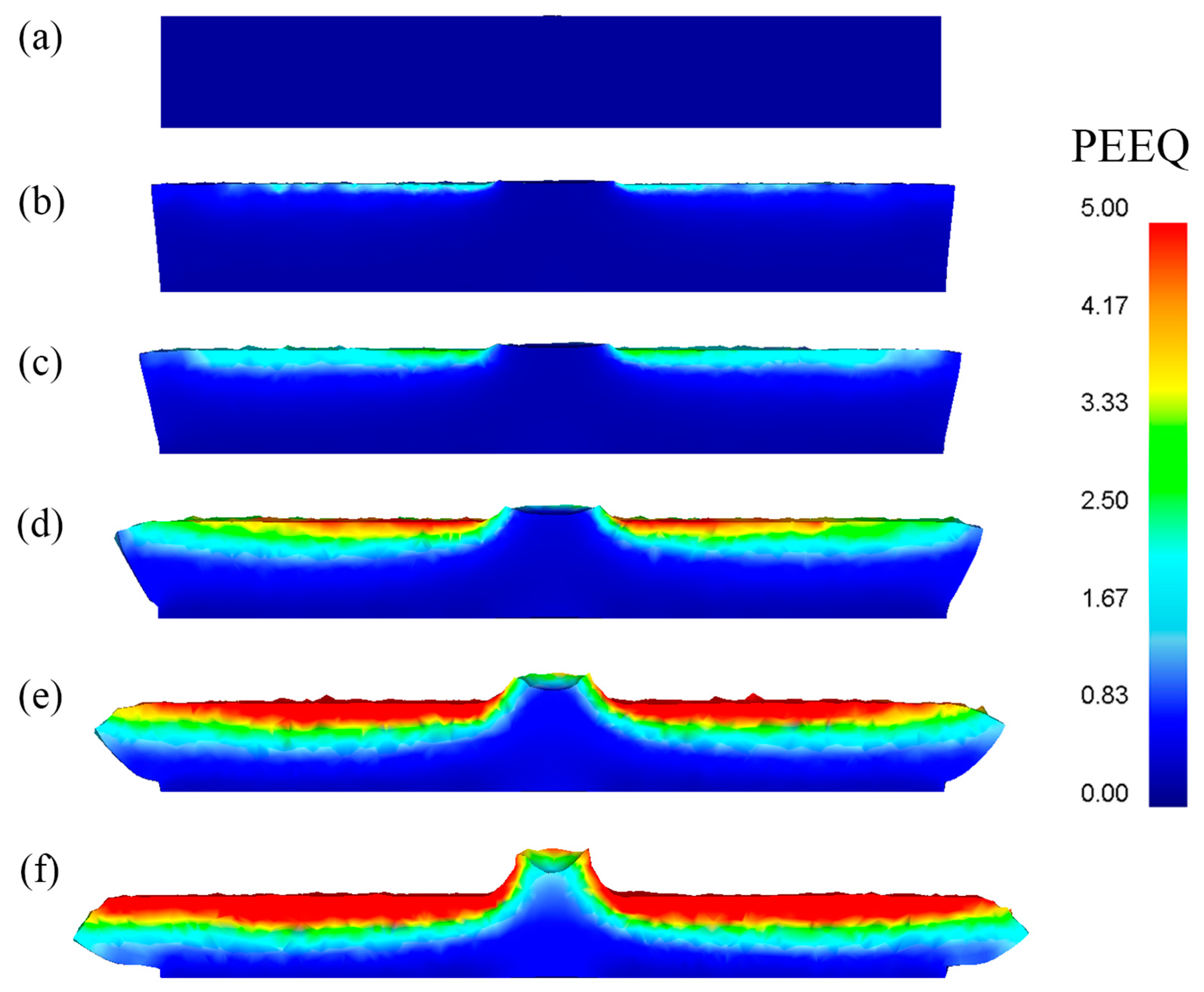
4.2. Deformation Characteristic of Strain Distribution

Figure 6 shows the axial section of the equivalent plastic strain distribution (PEEQ) of the disk workpiece during the forming process. As the upper die and the disk workpiece are in partial contact, the contact area of the upper die and the disk workpiece is smaller than that between the lower die and the disk workpiece. Therefore, the average axial compressive stress on the upper surface of the disk workpiece is greater than the lower surface of the disk workpiece, causing the inner side of the upper surface of the disk workpiece to first enter the state of plastic deformation, as shown in Figure 6b. Under the action of the oscillation of the upper die and the axial feed of the lower die, the stress wave is gradually transferred from the upper surface of the disk workpiece to the lower surface of the disk workpiece, making the plastic deformation zone gradually transfer from the inner and the upper surface of the disk workpiece to the outside and the lower surface of the disk workpiece, as shown in the Figure 6c. With the increase in the forming time, the plastic deformation zone penetrates the outer surface of the disk workpiece, as shown in Figure 5d. Then the plastic deformation continues to expand toward the lower surface of the disk workpiece, as shown in Figure 6e–f.
Different from rotary forging, it is difficult for the plastic deformation zone to penetrate the center region of the disk workpiece. This is because there is a certain distance between the two cones of the double-roll rotary forging, which is to prevent the cone rolls from colliding.

4.3. Influence of Three Key Parameters on Metal Flow

Figure 7 shows the influence of the growth rate of the upper surface diameter, the growth rate of the lower surface diameter, the growth rate of the maximum diameter, and the extent of the local flow at different heights Lf with different feed rate v of the lower die on the metal flow. From Figure 7a, the growth rate of the upper surface diameter of the disk workpiece has similar flow laws with different feed rates v of the lower die, which is a unique characteristic of rotary forging as the plastic deformation zone gradually develops and the upper surface of the disk workpiece to the lower surface of the disk workpiece. When the deformation degree is less than 20%, the plastic deformation of the lower surface of the disk workpiece is very small, and the growth rate of the lower surface diameter is very small. When the deformation degree is greater than 20%, the plastic deformation degree of the lower surface of the disk workpiece is relatively large, so the growth rate of the lower surface diameter is relatively high, as shown in Figure 7b. By comparing Figure 7a,b, it can be seen that the growth rate of the upper surface diameter of the disk workpiece is always greater than the growth rate of the lower surface diameter of the disk workpiece. This is because the upper surface of the disk workpiece has a higher degree of deformation than the lower surface of the disk workpiece and there will be friction heat generation between the upper surface of the disk workpiece and the upper die. Figure 7c shows that the growth rate of the maximum diameter shows a linear growth law, and the feed rate v of the lower die has almost no effect on the growth rate of the maximum diameter, which indicates that the growth rate of the maximum diameter cannot be regulated by changing the feed speed v of the lower die. From Figure 7d, the extent of the local flow at different height Lf curves shows similar flows and goes up slowly at the same deformation extent with the decrease feed rate v of the lower die. This is due to it being at the same degree deformation; the smaller the feed speed v of the lower die is, the smaller the deformation degree of the lower surface, and the greater the degree of inhomogeneous extent of the disk workpiece.
Figure 8 shows the influence of the growth rate of the upper surface diameter, the growth rate of the lower surface diameter, the growth rate of the maximum diameter, and the extent of the local flow at different heights Lf with different rotational speed n of the upper die on the metal flow. From Figure 8a, the growth rate of the upper surface diameter shows a nonlinear growth trend with the increase in the deformation extent and is little affected by the rotational speed n of the upper die. From Figure 8b, the growth rate of the lower surface diameter presents a lower growth rate before 20% deformation extent, and after that, the curves rise rapidly. From Figure 8c, the growth rate of the maximum diameter shows a linear relationship with the increase in the deformation extent, and the rotational speed n of the upper die does not affect the growth rate of the maximum diameter. From Figure 8d, the extent of the local flow at different heights Lf increases rapidly before the 20% deformation extent and, after that, the curves rise slowly. In addition, the rotational speed n of the upper die does not affect the degree of inhomogeneous extent of the disk workpiece.
Figure 9 shows the interactive influence of the feed amount per revolution S and initial temperature T of the disk workpiece on the growth rate of the upper surface diameter, the growth rate of the lower surface diameter, the growth rate of the maximum diameter, and the extent of the local flow at different heights Lf. From Figure 9a–c, with the increase in the initial temperature T of the disk workpiece, the growth rate of the upper surface diameter, the growth rate of the lower surface diameter, the growth rate of the maximum diameter, and the extent of the local flow at different heights Lf do not change significantly. Additionally, with the increase in the feed amount per revolution S, the growth rate of the upper surface diameter, the growth rate of the lower surface diameter, and the growth rate of the maximum diameter do not change significantly, and the extent of the local flow at different heights Lf increases slightly. Altogether, the feed amount per revolution S and initial temperature T of the disk workpiece has little effect on the metal flow.

4.4. Influence of Three Key Parameters on the Force and Power Parameters

Figure 10 shows the influence of the feed rate v of the lower die on the maximum axial force and forging moment. From Figure 10, with the increasing feed rate v of the lower die, the maximum axial force and forging moment first increase slowly and then increase rapidly as the feed rate v of the lower die increases. This is because, with the increase in the feed rate v of the lower die, more metal comes into the plastic deformation state. Thus, more energy is needed to produce the plastic deformation.
Figure 11 shows the influence of the rotational speed n of the upper die on the maximum axial force and forging moment. From Figure 11, with the increase in the rotational speed n of the upper die, the maximum axial force and forging moment first decrease rapidly and then decrease slowly as n exceeds 75 rad/min. When the rotational speed n of the upper die is smaller than 75 rad/min, with an increase in the rotational speed n of the upper die, the transfer rate of metal increases significantly, so the maximum axial force and forging moment decrease rapidly. However, when the rotational speed n of the upper die is larger than 75 rad/min, the transfer rate of metal does not increase with the increase in the rotational speed n of the upper die. Therefore, increasing the rotational speed n of the upper die has relatively little effect on the maximum axial force and forging moment.
Figure 12 shows the interactive influence of the feed amount per revolution S and the initial temperature T of the disk workpiece on the maximum axial forging force and forging moment. It can be seen that with a fixed feed speed v of the lower die and changing the feed amount per revolution S, the maximum axial forging force and forging moment first decrease rapidly and then decrease slowly with the increase in the initial temperature T of the disk workpiece. This is because, with the increasing in the initial temperature T of the disk workpiece, it is easier for the disk workpiece to enter the plastic deformation state. Thus, less energy is needed to produce the plastic deformation. It can also be seen from Figure 12 that the greater the feed amount per revolution S is, the more significant the effect of the initial temperature T of the disk workpiece. This indicates that the maximum axial forging force and forging moment can be more effectively controlled by the initial temperature T of the disk workpiece. Additionally, with the increase in initial temperature T, the effect of the feed amount per revolution S on the maximum axial forging force and forging moment becomes less significant.
Further study of Figure 12 reveals that for any feed amount per revolution S ranging from 0.4 mm·r−1 to 2.5 mm·r−1 when the initial temperature T of the disk workpiece is below 1100 °C, the maximum axial forging force and forging moment decrease significantly with the decrease in the feed amount per revolution S. When the initial temperature T of the disk workpiece is located in the range from 1100 to 1200 °C, the maximum axial forging force and forging moment decrease with the decrease in the feed rate v of the lower die.

5. Conclusions

In this work, the deformation characteristic and the effective laws of three key parameters (feed rate v of the lower die, rotational speed n of the upper die, and the temperature T of the disk workpiece) on the metal flow and force and power parameters in the double-roll rotary forging process have been explored. The results are as follows:
(1) The PEEQ distribution exhibits a transfer characteristic from the upper surface to the lower surface of the disk workpiece. At the beginning of the forming process, the plastic deformation zone is formed firstly at the inner side of the upper surface of the disk workpiece. With the increase in the forming time, the plastic deformation zone penetrates the outer surface of the disk workpiece, and then the plastic deformation continues to expand toward the lower surface of the disk workpiece.
(2) The feed rate v of the lower die, rotational speed n of the upper die, feed amount per revolution S, and initial temperature T of the disk workpiece have almost no effect on the growth rate of the upper surface diameter, the growth rate of the lower surface diameter, and the growth rate of the maximum diameter. Increasing the feed speed v of the lower die can reduce the extent of the local flow at different heights Lf, and changing the rotational speed n of the upper die has little effect on the extent of the local flow at different heights Lf.
(3) Increasing the feed rate v of the lower die, the maximum axial force and forging moment first increase slowly and then increase rapidly as the feed speed v of the lower die increases. With the increase in the rotational speed n of the upper die, the maximum axial force and forging moment first decrease rapidly and then decrease slowly as the rotational speed n of the upper die increases. With an increase in the initial temperature T of the disk workpiece, the maximum axial force and forging moment first decrease rapidly and then decrease slowly when the initial temperature T of the disk workpiece is higher than 1100 °C.

Author Contributions

Z.Y. and C.Z. proposed the idea and performed the theoretical work. Z.Y. and C.Z. completed the writing of the paper. Z.Y., M.C., C.M. and S.L. performed the experimental work. All authors have read and agreed to the published version of the manuscript.

Funding

This research was funded by National Natural Science Foundation of China (No.51875427).

Data Availability Statement

The datasets used or analyzed during the current study are available from the corresponding author on reasonable request.

Acknowledgments

The authors acknowledge all of the authors who contributed to this article and the teachers who provided the theoretical analysis.

Conflicts of Interest

The authors declare that they have no known competing financial interests or personal relationships that could have appeared to influence the work reported in this paper.

References

  1. Li, Q.; Wu, L.; Li, F.; Liu, T.; Wang, S.; Wei, Z.; Su, C. Experiments study on the rolling process for heavy disk. Int. J. Adv. Manuf. Technol. 2013, 65, 1171–1175. [Google Scholar] [CrossRef]
  2. Ma, Q.; Lin, Z.Q.; Yu, Z.Q. Prediction of deformation behavior and microstructure evolution in heavy forging by FEM. Int. J. Adv. Manuf. Technol. 2009, 40, 253–260. [Google Scholar] [CrossRef]
  3. Zhbankov, I.G.; Perig, A.V.; Aliieva, L.I. New schemes of forging plates, shafts, and discs. Int. J. Adv. Manuf. Technol. 2016, 82, 287–301. [Google Scholar] [CrossRef]
  4. Li, Q.; Ma, Z.; Liu, T.; Li, F.; Wei, Z.; Su, C. 3D thermomechanically coupled FEM analysis of large disk rolling process and trial production. Int. J. Adv. Manuf. Technol. 2014, 74, 403–411. [Google Scholar] [CrossRef]
  5. Peng, W.; Zhang, D.; Zhao, D. Application of parabolic velocity field for the deformation analysis in hot tandem rolling. Int. J. Adv. Manuf. Technol. 2017, 91, 2233–2243. [Google Scholar] [CrossRef]
  6. Zhou, P.; Zhang, L.; Gu, S.; Ruan, J.; Teng, L. Mathematic modeling and FE simulation of radial-axial ring rolling large L-section ring by shape axial roll. Int. J. Adv. Manuf. Technol. 2014, 72, 729–738. [Google Scholar] [CrossRef]
  7. Canta, T.; Frunza, D.; Sabadus, D.; Tintelecan, C. Some aspects of energy distribution in rotary forming processes. J. Mater. Process. Technol. 1998, 80–81, 195–198. [Google Scholar] [CrossRef]
  8. Decheng, Z.; Yadong, H.; Wang, Z.R. Research on rotary forging and its distribution of deformation. J. Mater. Process. Technol. 1992, 31, 161–168. [Google Scholar] [CrossRef]
  9. Oudin, J.; Ravalard, Y.; Verwaerde, G.; Gelin, J.C. Force, torque and plastic flow analysis in rotary upsetting of ring shaped billets. Int. J. Mech. Sci. 1985, 27, 761–780. [Google Scholar] [CrossRef]
  10. Wang, G.C.; Guan, J.; Zhao, G.Q. A photo-plastic experimental study on deformation of rotary forging a ring workpiece. J. Mater. Process. Technol. 2005, 169, 108–114. [Google Scholar]
  11. Decheng, Z.; Shijian, Y.; Wang, Z.R.; Zhenrui, X. Defects caused in forming process of rotary forged parts and their preventive methods. J. Mater. Process. Technol. 1992, 32, 471–479. [Google Scholar] [CrossRef]
  12. Oh, H.K.; Choi, S. A study on center thinning in the rotary forging of a circular plate. J. Mater. Process. Technol. 1997, 66, 101–106. [Google Scholar] [CrossRef]
  13. Yuan, S.; Wang, X.; Liu, G.; Chou, D. The precision forming of pin parts by cold-drawing and rotary-forging. J. Mater. Process. Technol. 1999, 86, 252–256. [Google Scholar] [CrossRef]
  14. Liu, G.; Yuan, S.J.; Wang, Z.R.; Zhou, D.C. Explanation of the mushroom effect in the rotary forging of a cylinder. J. Mater. Process. Technol. 2004, 151, 178–182. [Google Scholar] [CrossRef]
  15. Liu, G.; Zhang, L.B.; Hu, X.L.; Wang, Z.R.; Wang, R.W.; Huang, S.D.; Tang, Q.B. Applications of numerical simulation to the analysis of bulk-forming processes—Case studies. J. Mater. Process. Technol. 2004, 150, 56–61. [Google Scholar] [CrossRef]
  16. Han, X.; Hua, L. Comparison between cold rotary forging and conventional forging. J. Mech. Sci. Technol. 2009, 23, 2668–2678. [Google Scholar] [CrossRef]
  17. Han, X.; Hua, L. 3D FE modeling of cold rotary forging of a ring workpiece. J. Mater. Process. Technol. 2009, 209, 5353–5362. [Google Scholar] [CrossRef]
  18. Hua, L.; Han, X. 3D FE modeling simulation of cold rotary forging of a cylinder workpiece. Mater. Des. 2009, 30, 2133–2142. [Google Scholar] [CrossRef]
  19. Mandal, P.; Lalvani, H.; Tuffs, M. Cold rotary forging of inconel 718. J. Manuf. Process. 2019, 46, 77–99. [Google Scholar] [CrossRef]
  20. Mandal, P.; Lalvani, H.; Watt, K.; Conway, A.; Tuffs, M. A study on microstructural evolution in cold rotary forged nickel-superalloys: C263 and Inconel 718. Procedia Manuf. 2020, 47, 1403–1409. [Google Scholar] [CrossRef]
  21. Zheng, Y.; Liu, D.; Yang, Y.; Zhang, Z.; Li, X. PDZ evolution of hot ACDR and forging processes during titanium alloy disc forming. Int. J. Adv. Manuf. Technol. 2018, 95, 1635–1643. [Google Scholar] [CrossRef]
  22. Zheng, Y.; Liu, D.; Yang, Y.; Zhang, Z.; Li, X.; Zhang, R. Microstructure evolution of Ti-6Al-4V with periodic thermal parameters during axial closed die rolling process. J. Alloys Compd. 2018, 735, 996–1009. [Google Scholar] [CrossRef]
  23. Zheng, Y.; Liu, D.; Yang, Y.; Ren, L.; Zhang, Z.; Gao, G. Investigation on metal flow during the hot axial closed die rolling process for titanium alloy discs. Int. J. Adv. Manuf. Technol. 2016, 87, 2445–2458. [Google Scholar] [CrossRef]
  24. YZheng, Y.; Liu, D.; Zhang, Z.; Yang, Y.; Ren, L. The flow line evolution of hot open ACDR process for titanium alloy discs. Arch. Civ. Mech. Eng. 2017, 17, 827–838. [Google Scholar] [CrossRef]
  25. Shi, L.; Zhu, C.D.; Liu, X.; Zhang, Y. Optimum design of the double roll rotary forging machine frame. Mech. Sci. 2020, 11, 101–114. [Google Scholar] [CrossRef] [Green Version]
Figure 1. Working principle of integral forming of large diameter thin-walled metal disk double-roller rotary forging.
Metals 11 01767 g001
Figure 2. The numerical model of the integral forming of the large diameter thin-walled metal disk by double-roll rotary forging.
Metals 11 01767 g002
Figure 3. The stress–strain curves of AISI-1020. (a)The strain rate is 2. (b)The strain rate is 20.
Metals 11 01767 g003
Figure 4. Definition of the growth rate of upper surface diameter φupper, the growth rate of lower surface diameter φlower, the growth rate of maximum diameter φmax, and the extent of local flow at different heights Lf.
Metals 11 01767 g004
Figure 5. (a) Double-roller rotary forging equipment. (b) Disk workpiece experiment and numerical simulation process. (c) Physical photos of the workpiece temperature measurement, t = 10 s. (d) A photograph of the deformed disk workpiece.
Metals 11 01767 g005
Figure 6. PEEQ distribution of axial section of disk workpiece with time. (a) t = 0 s; (b) t = 1.62 s; (c) t = 2.69 s; (d) t = 4.99 s; (e) t = 7.45 s; (f) t = 9.95 s.
Metals 11 01767 g006
Figure 7. Influence of feed rate v of the lower dies on metal flow during the hot double-roll rotary forging process. (a) The growth rate of upper surface diameter. (b) The growth rate of lower surface diameter. (c) The growth rate of maximum diameter. (d) The extent of local flow at different heights Lf.
Metals 11 01767 g007
Figure 8. Influence of rotational speed n of the upper dies on metal flow during the hot double-roll rotary forging process. (a) The growth rate of upper surface diameter. (b) The growth rate of lower surface diameter. (c) The growth rate of maximum diameter. (d) The extent of local flow at different heights Lf.
Metals 11 01767 g008
Figure 9. Influence of the feed amount per revolution S and initial temperature T of the disk workpiece on metal flow during the hot double-roll rotary forging process. (a) The growth rate of upper surface diameter. (b) The growth rate of lower surface diameter. (c) The growth rate of maximum diameter. (d) The extent of local flow at different heights Lf.
Metals 11 01767 g009
Figure 10. Influence of feed rate v of the lower die on the maximum axial forging force and forging moment: (a) influence of feed rate v of the lower die on the maximum axial forging force; (b) influence of feed rate v of the lower die on the maximum forging moment.
Metals 11 01767 g010
Figure 11. Influence of rotational speed n of the upper die on the maximum axial forging force and forging moment: (a) influence of rotational speed n of the upper die on the maximum axial forging force; (b) influence of rotational speed n of the upper die on the maximum forging moment.
Metals 11 01767 g011
Figure 12. Interactive influence of feed amount per revolution S and initial temperature T of the disk workpiece on the maximum axial forging force and forging moment: (a) Interactive influence of feed amount per revolution S and initial temperature T of the disk workpiece on the maximum axial forging force; (b) Interactive influence of feed amount per revolution S and initial temperature T of the disk workpiece on the maximum forging moment.
Metals 11 01767 g012
Table 1. Mechanical and thermal properties of disk workpieces.
Simulation ParametersAISI-1020
Density, ρ (kg·m−3)7800
Young’s modulus (GPa)210
Poisson’s ratio (μ)0.3
Thermal conductivity (J/(m·s·K))24.5
Specific heat capacity (J/(kg·K)7.2
Thermal expansion coefficient (1/K)13.16 × 10−6
Constitutive equation σ ¯ = σ ¯ ( ε ¯ , ε ¯ ˙ ,   T )
Table 2. Parameters in the numerical simulation process for verification.
ParametersValue
The initial diameter of disk workpiece D0 (mm)244
The initial height of disk workpiece H0 (mm)35
Height reduction (%)66.7
Rotational speed n of the upper die (rad/min)75
Feed rate v of the upper die (mm/s)1
The initial temperature of the disk workpiece (°C)1100
The initial temperature of die T (°C)20
Coefficient of friction between upper die and disk workpiece0.1
Coefficient of friction between lower die and workpiece0.7
Thermal conductivity between die and disk workpiece (kW/m2·°C)15
Table 3. Processing parameters of 3D numerical of disk of double-roll rotary forging.
ParametersValue
The initial diameter of disk workpiece D0 (mm)244
The initial height of disk workpiece H0 (mm)35
Height reduction (%)33.3
Rotational speed n of the upper die (rad/min)50, 75, 100, 125, 150
Feed rate v of the upper die (mm/s)0.5, 1, 1.5, 2, 2.5
Feed amount per revolution S (mm/r)0.4, 0.8, 2.5
Initial temperature T of the disk workpiece (°C)1000, 1050, 1100, 1150, 1200
Publisher’s Note: MDPI stays neutral with regard to jurisdictional claims in published maps and institutional affiliations.

