1. Introduction
In automotive applications, weight reduction, acoustic insulation, and crash absorption are crucial points for materials to be used.
The use of foams for the absorption of acoustic vibrations in trucks has been investigated [
1], but mainly considering polymeric foams which can have some concerns related to fire and temperature resistance and recyclability.
Moreover, the aluminum realization of hollow structures has been investigated for weight reduction by using sand cores [
2]. However, this approach requires complex process design and can often lead to critical conditions in term of resistance.
Aluminum foams have been investigated as promising materials to match weight saving and crash energy/vibrations absorption in automotive applications [
3,
4]
Aluminum foams have also been proposed in order to locally increase mechanical properties of hollow aluminum structures, with the advantage of also introducing crash energy absorption and acoustic insulation [
5].
In this context, the use of Al-based metal foams as permanent cores in the casting of Al-alloy can give numerous advantages, such as weight reduction compared to dense components, the obtainment of cavities in cast objects, strength increase in terms of hollow or T-shaped sections, impact energy and vibration absorption, acoustic insulation, and the simplification of the technological processes (no removal/recycling of traditional sand cores) and recyclability, compared to traditional sand cores [
6]. However, this application is still poorly explored in the scientific literature (just a few papers/year, fewer than 10 patents published on this topic) in contrast with the increasing research and publication related to metal foams (from 100 papers/year to 600 papers/year in the last 20 years) [
6].
Some attempts to use Al foam cores in casting experiments have been reported in the literature [
7,
8,
9,
10,
11] and all these papers highlight the presence of an external continuous skin as a crucial parameter to avoid the infiltration of molten metal in the foam core porosity during casting. Moreover, in the cited works, it is reported that partial melting of the core surface during the molten metal-core contact is a key point for metallurgical bonding.
The production of a cast object with a foam core is also described in some patents [
12,
13,
14,
15], evidencing the technological and industrial interest in this kind of application of metal foams.
In the present paper, Cymat-type Al-based foams with a thin outer skin were considered possible permanent cores in gravity casting experiments with an Al-Si-Cu-Mg alloy (EN AB-46400). The foam inserts, with different density and pore size, were characterized in terms of porosity, pore dimensions, wall and skin thickness, and compression resistance. The cast objects with the foam cores were analyzed by means of optical microscopy to determine residual porosity, core-shell bonding, and microstructure.
The main aim of the introduction of foam inserts in aluminum casting is the realization of functional cavities, able to reduce component weight and introduce functional properties such as energy and vibration absorption ability.
The results are compared with those previously obtained by the authors with Havel Metal Foam type Al-based foams with a thick outer skin. The key points driving porosity maintenance and core-shell bonding are critically discussed as well as possible improvements.
2. Materials and Methods
Cymat-type Al-based foams (Al alloy with SiC particles as stabilizing agent, Cymat Technologies Ltd., Mississauga, ON, Canada) were acquired in the form of rectangular panels and cut into the form of bars (transversal section: 22 mm × 12.7 mm or 12 mm, length 122 mm) for casting experiments as well as of small rectangular samples for physical and chemical characterizations. In this configuration, a continuous thin surface skin was present only on the top and bottom surfaces of the samples but not on perpendicular sides.
Three foams with different densities (
Figure 1) were used for both characterization and casting experiments.
The density of the foams was calculated from weight and volume measurements on three representative bar samples per foam type. The average porosity of the foams was obtained from these data. Moreover, a “metallographic porosity” was estimated from image analyses on the cross section of the foam samples to be compared with the one of the same foams after insertion in casting. For the evaluation of the “metallographic porosity”, three samples for foam type, around 130 mm2 each, were embedded in dark-colored resin (methyl methacrylate base plus catalyst) and metallographically polished. The image of the samples was digitalized with a high-resolution scanner. The regions of interest of the digital images, excluding the resin, were improved in contrast and brightness, corrected from shot and dark noise, and the Image segmentation and Erode and dilate filter were applied. In all cases, the final binary images were compared with the initial ones to evaluate the goodness of the digital image processing.
Small samples (1–2 cm side) were resin mounted and metallographically polished for optical and electronical microscopy analyses on the foam cross section.
The samples were observed by optical microscope (Reichert-Jung MeF3, Leica Microsystems Srl, Buccinasco (MI), Italy) in order to investigate the microstructure and to determine the pore dimensions, the thickness of the skin and of the pore walls by means of images processing by ImageJ software (Image J2 version, Fiji). The values of pore dimensions and skin and pore wall thickness were obtained from 50 measurements for each foam type. The measurement of pore size was obtained by the Feret’s method, normally used for the measurement of the sizes of irregular shape particles.
The morphology and semi-quantitative chemical composition of Al-foams were investigated by means of Scanning Electron Microscopy equipped with Energy Dispersive Spectroscopy (SEM-EDS JEOL, JCM 6000 plus and JED 2300). The external surface of the foam samples was analyzed in the as-received and after washing conditions (5 min acetone in ultrasonic bath) or after grinding (SiC paper 320 grit) and washing (as before) in order to investigate the surface features involved in the reaction with the molten metal in casting experiments.
Compression tests were performed on foam samples of 57 mm × 20 mm (dimension of the rectangular top section) and a thickness, depending on the foam type, of 11 mm (foam 1) or 13 mm (foam 2 and 3). Samples of metal foams (not inserted in casting) were used for the mechanical characterization. The compressive force was applied on the rectangular top section (with thin continuous skin). The sample width was selected in order to be at least 7 times the mean pore size, as suggested in the scientific literature and in international standards [
16,
17,
18] to avoid measurements artifacts. The test was performed with a speed of 1 mm/min (according to [
16,
17,
18], up to a 25 kN maximum load). Three samples per foam type were tested. In order to take into account the differences in samples’ thickness percentage, relative displacement, calculated as displacement/sample thickness, was reported in data comparison.
Foam bars samples, analogous to the ones previously characterized, were used as permanent cores in gravity casting experiments. A mold with stepped geometry, designed ad hoc for the experiment and shown in
Figure 1d, was used for aluminum casting with the foam inserts. This stepped die foresees 2 steps (step 1–6 mm thick and step 2–11 mm thick) without foam inserts and two steps, with foam inserts (step 3 and step 4 with nominal thickness of the dense metal around the foam analogous to that of the steps 1 and 2, respectively). The foam samples were positioned with the thinner cross-section (that without continuous skin) perpendicular in respect to the molten metal flow, as indicated in
Figure 1d. The cast specimen containing foam 1 as core is denoted as S3, the one containing foam 2 as S1, and the one with foam 3 as S4.
The Al-Si-Cu-Mg alloy (EN AB-46400) was used in the casting experiments and an example of the obtained cast objects with foam inserts is shown in
Figure 1e.
Cast products were longitudinally sectioned (following indicatively the red dotted line in
Figure 1e) and visually observed in order to estimate the degree of infiltration of metal foam cores from the molten metal. Small samples of the different zones were collected, resin mounted, mirror polished, and analyzed at the optical microscope to investigate the residual porosity and the amount of the cast metal-foam core interface. Moreover, optical microscopy analyses (100× magnification images) on small samples of the cast metal (without foam core) were used to calculate the Secondary Dendrites Arm Spacing (SDAS) by dividing the length of the principal dendrite by the number of secondary arms minus 1, as suggested in [
19]. This parameter depends on the metal cooling rate and can be correlated with the mechanical properties of the cast object (microhardness, yield strength) [
19,
20,
21].
Results obtained with the above-described types of foam were compared with the ones previously obtained using Al-based metal foams with a dense and thick outer skin (AF1; Al alloy with a limited amount of TiH
2 as the foaming agent, Havel Metal Foams GmBH, Brandenburg an der Havel, Germany) [
22,
23].
3. Results and Discussion
The visual appearance of the Cymat-type foams, used in the present research, is shown in
Figure 1. Foam 1 presents very big pores while smaller ones can be observed on foams 2 and 3. All the foams show a high variability in pore size and shape and a very thin and irregular surface outer skin, as reported for Cymat type Al-based foams [
6].
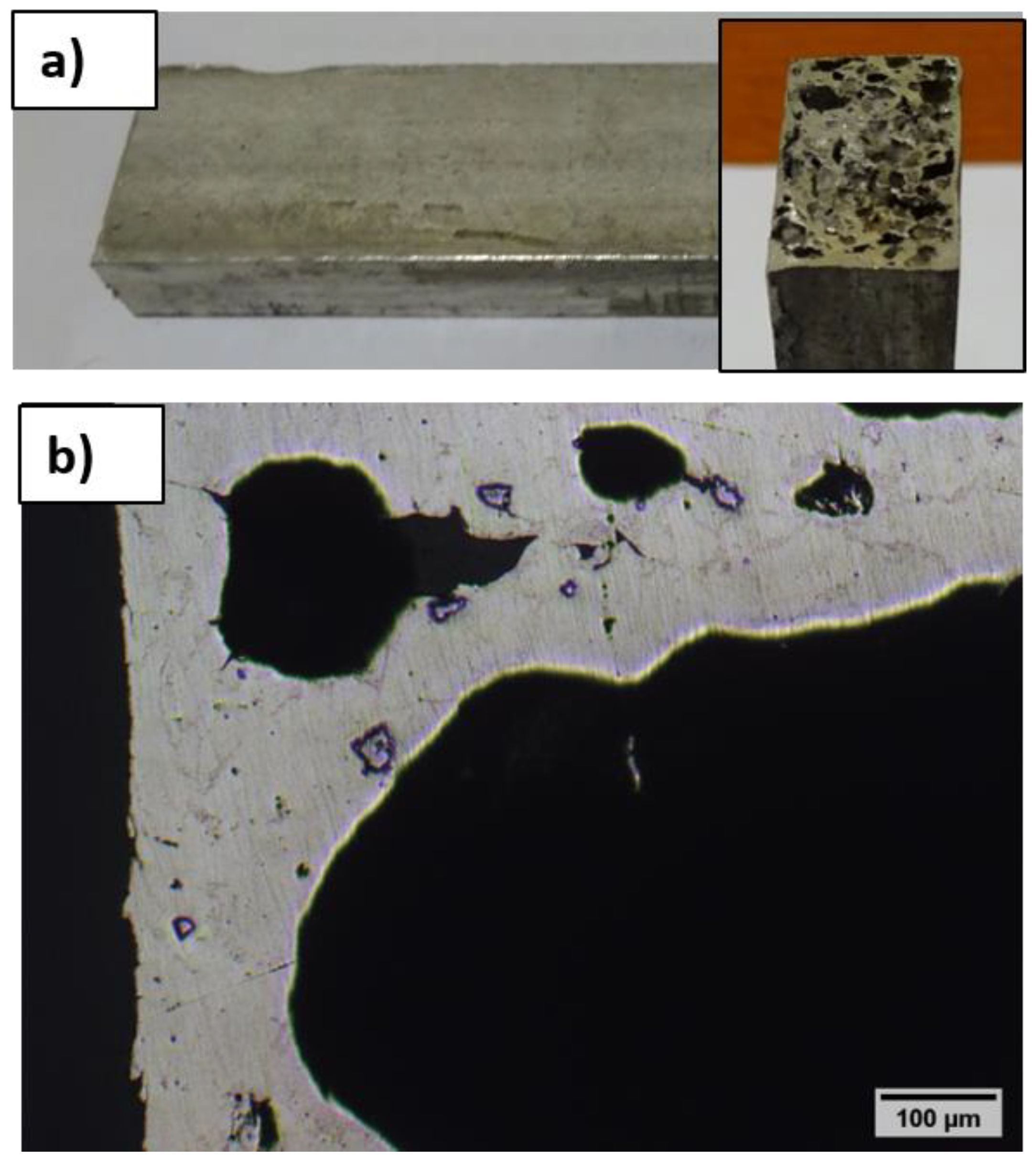
On the other hand, the Havel Metal Foam inserts, used in previous experiments [
23], present smaller pores and a more homogeneous and thicker outer skin, as shown in
Figure 2 for comparison.
For all the tested Cymat-type foams, the density, pore dimensions and outer skin and wall thickness are reported in
Table 1. The density of foam 1 was almost half of the one of foam 2 and 3 which were closer in value, confirming visual observation (
Figure 1). Accordingly, the average porosity was higher for foam 1, compared to foam 2 and 3. These differences were less evident when the metallographic porosity was calculated from optical microscopy images. This difference can be associated with the high variability in pore dimension and distribution which can more significantly affect these measurements and they are only performed on some metallographic sections. However, these values can be useful for a semi-quantitative evaluation of the infiltration degree when foam samples are used as permanent cores in casting experiments. The relative density of this type of foam is lower than the one reported for the HMF one (0.4–0.6) [
22].
Pore dimensions showed doubled values for foam 1 and more similar values for foams 2 and 3 according again with visual inspection (
Figure 1). Pore dimension showed a high variability which can be correlated with the foam production process (direct gas injection in the molten metal) which leads to the development of a stochastic structure [
24].
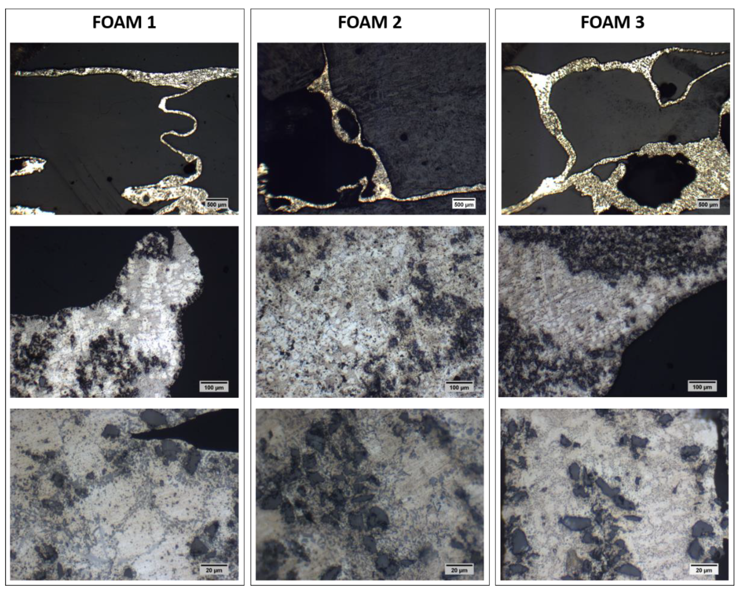
Cell walls and outer skin thickness were similar in thickness (100–200 µm), as can also be observed from
Figure 3 (first row). Both parameters presented a very low variability in their minimum values among the different foams, while the maximum values were always higher for foam 1. In all cases, a high dispersion between the minimum and the maximum values could be observed. In comparison, a significantly thicker outer skin was measured for HMF foams (up to 1200 µm) [
22,
23].
Optical microscope images of the foams’ cross sections, at 100× and 500× magnifications, are reported in
Figure 3 (second and third rows, respectively). The lighter areas can be ascribed to α-phase (rich in Al) with dendritic structure which is surrounded by light gray zones attributable to the Al-Si eutectic structure. Moreover, a high amount of dark gray particles could be observed, mainly at the surface. They could be SiC particles, frequently used to increase the molten metal viscosity in Cymat type Al foam production [
6,
25,
26,
27,
28].
The different composition and production route of these foams result in a different microstructure compared to the HMF one (See
Figure 2b for comparison). As reported in [
23], HMF foams present Ti-rich particles associated with the powder metallurgy technology, which uses TiH
2 as foaming agent and no stabilizing additives (SiC).
Semi-quantitative chemical composition of the foams was determined by EDS analyses on different areas of the foam cross section and reported in the bar graph of
Figure 4a. The main elements detected on the foams were Al (the main constituent of the base metal), Si (which can be present as alloying element or as silicon carbide, the stabilizing agent), and oxygen (attributable to oxidation). Carbon could be associated to the presence of silicon carbide and minimally to surface contamination.
SEM observations and localized EDS analyses on second phases particles and base metal are reported in
Figure 4b. It can be observed that the base metal (EDS 2) was mainly constituted by Al and Si, as expected and as previously reported for the whole cross section, with minimal oxidation. Cr can be referred to surface metallization of resin mounted samples. EDS analyses on the “second phases particles” evidenced two different typologies: EDS 1 (bigger particles) reports only Si while EDS 3 (smaller particles) showed both Si and C as main elements. These observations suggest the presence of both Si and SiC particles. Micro-hardness measurements (
Figure 4c) confirm this hypothesis: the smaller particles had the highest hardness and could reasonably be SiC particles, the bigger ones had an intermediate hardness and could be Si particles while the base metal presented the lower HV value.
EDS analyses were performed also on the external surface of the foams samples as received and after washing or grinding and washing in order to better understand the surface reactions with molten metal in casting experiments, as previously reported for HMF foams [
23]. Results are reported (for foam 3, as example) in the bar graph of
Figure 5a. The surface skin of the as-received foams was mainly constituted of Al and Si, similarly to the cross section, with limited amounts of O and C attributable to oxides and contaminations or SiC, respectively. The SEM image of
Figure 5b confirms the presence of small oxide deposits (evidenced by box 1 with EDS analysis which shows high oxygen content compared to the base metal, box 2). Washing reduces both the carbon and oxygen amounts evidencing that some contaminations and oxides are weakly bonded to the surface and can be easily removed. On the other hand, only mechanical polishing would have allowed removal of magnesium oxides and carbonates, abundantly detected on the surface of HMF foams [
23].
The results of compression tests are shown in
Figure 6. Measurements were performed on 3 samples per foam type and, since the results obtained on each foam type were quite similar, one single curve for each foam was reported, for better readability.
All the curves evidenced three main zones, as typically for compression tests of metal foams [
29,
30]. A first zone showed a linear behavior, until around 5% of relative displacement, associated with structure elastic deformation. This zone ended at low loads (less than 200 N for foam 1, about 1500 N for foam 2, and around 4000 N for foam 3). A second zone with evident plastic deformations, at around constant load, showed a plateau typical for metal foams and it was associated with their energy absorption ability [
29,
30]. The sample thickness reduction, in the direction of the compressive force applied, could reach values up to 50% of the total thickness in this zone (e.g., for foam 1). The load increase in this second step was negligible in case of the foam 1 while it showed a slight increase in the case of foam 2 and 3. In this zone, the porous structure of the cell walls plastically deformed because the localized material resistance was exceeded. The final zone showed a sudden increase of the required load with moderate increase in the relative displacement percentage, compared to the previous zones, and it was associated with the final densification.
Compression tests evidenced a similar behavior for foams 2 and 3, with relative compression value around 20% and 30%, respectively, at 5000 N load. On the other hand, foam 1, at the same load (5000 N) presented a relative compression value of 65% and this load slightly exceeded the limit for constant load deformations. It could be observed that the compaction of the foams 2 and 3 was almost complete at around 50% of the relative displacement while that of foam 1 reached the value of 65%. This means that the effect of porosity was particularly evident in elastic and plastic regions of the curve, while, after pore collapse, the foams behavior became more similar, as well as the load required for the final compaction.
The visual appearance (top view and cross section) and the optical microscope images of cast objects with the different foams as inserts are shown in
Figure 7,
Figure 8 and
Figure 9.
When foam 1 was used as insert, almost complete infiltration from the molten metal occurred (
Figure 7). This phenomenon can be associated with the large open pores on the cross section which received the molten metal flow and with a thin outer skin on the lateral sides which, in presence of big porosities, is not able to resist to molten metal infiltration.
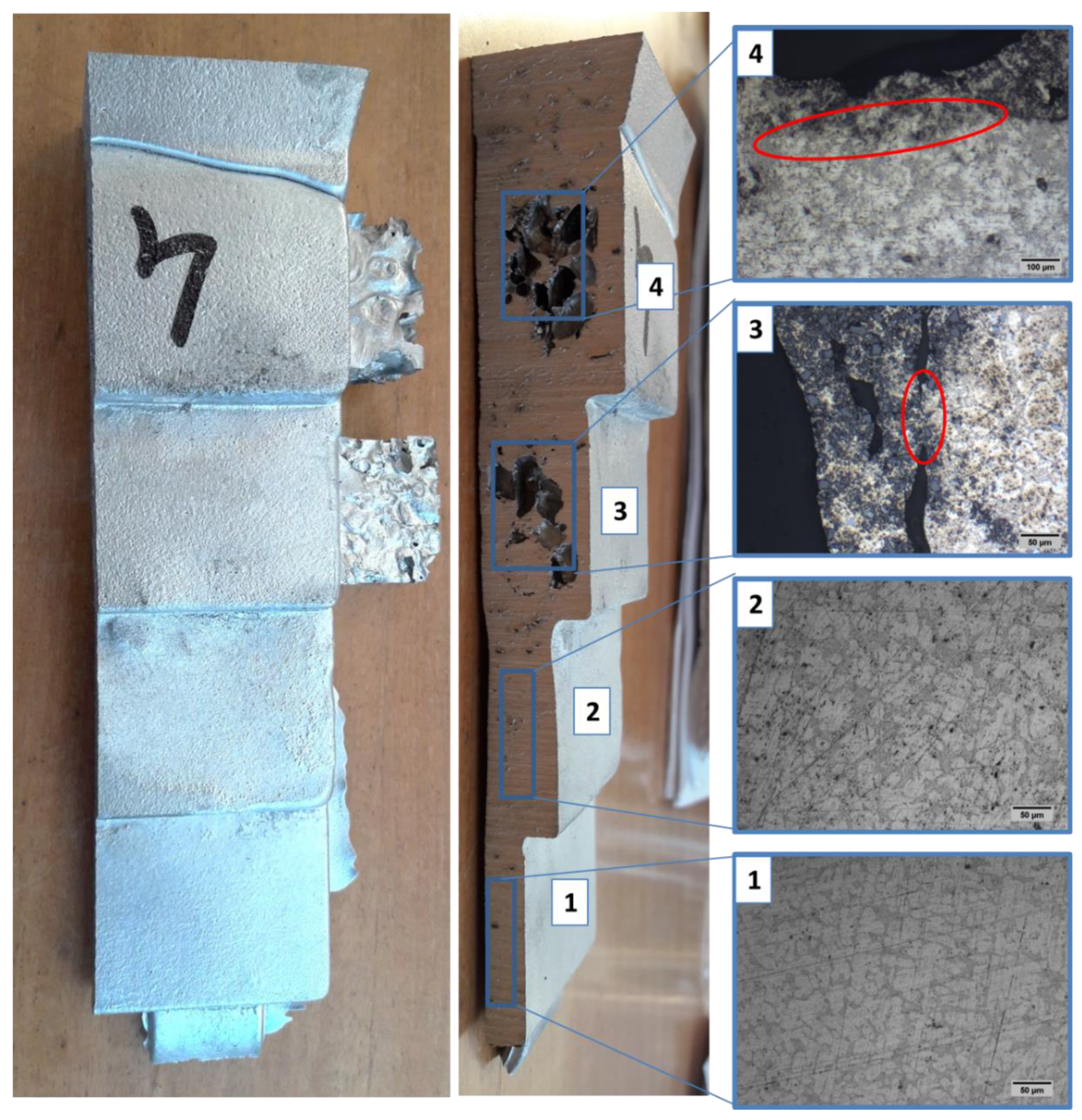
On the other hand, a certain amount of porosity was maintained in the case of foams 2 and 3 as inserts: 30–40% for S1 sample (
Figure 8) and at about 40% for S4 sample (
Figure 9), considering a transversal cross-section. Considering that, before insertion in casting the metallographic porosity was around 75% for these foams (
Table 1), it can be concluded that at about half of the foam porosity is maintained after their use as permanent cores in casting.
In contrast, no infiltration was observed using HMF foams, with thick outer skin as inserts [
22,
23]. These results confirm that the presence of a thick and continuous outer skin can effectively preserve foam cores from infiltration by molten metal, as reported in the literature [
7,
8,
9].
Looking at the optical microscope images, it can be observed that the cast Al-alloy presented a typical dendritic microstructure with an Al-rich phase (the lighter one, α-phase) surrounded by a eutectic Al-Si structure, in the dense metal zone of steps 1 and 2 (without foam inserts) and around foam inserts in step 3 and 4 zones.
In
Figure 8 and
Figure 9, the interface between the foam inserts and the cast metal can be observed in steps 3 and 4. A certain gap (few microns) can be noticed in some points, in other areas (evidenced by red ovals), even if a metallurgical continuity can be observed between the two structure, evidencing a certain degree of bonding. The microstructural continuity, with occasionally transfer of dark particles from the foam to the molten metal suggests a process of local melting of the inserts and the consequent metallurgical bonding between the structures. This phenomenon is favored by the limited presence of surface oxides on the outer skin and on the cell walls of the foams which often can reduce foam reactivity with the molten metal and acts as obstacle in metallurgical bonding as reported in [
6,
23,
31] and previously observed by the authors using HMF foams as cores [
22,
23].


 ,
, 


