Article

Carbonitriding of Forging Dies

by
Stefanie Hoja
*,
Heinrich Klümper-Westkamp
and
Matthias Steinbacher
Center for Materials and Processes, Leibniz-Institut für Werkstofforientierte Technologien–IWT and MAPEX, Universität Bremen, 28359 Bremen, Germany
*
Author to whom correspondence should be addressed.
Metals 2021, 11(10), 1651; https://doi.org/10.3390/met11101651
Submission received: 26 August 2021 / Revised: 12 October 2021 / Accepted: 14 October 2021 / Published: 18 October 2021
(This article belongs to the Special Issue Heat Treatment and Mechanical Properties of Metals and Alloys)

Abstract

:
Forging dies have to resist high mechanical and thermal loads. Therefore, they are usually nitrided. Former investigations showed that the abrasive wear at the critical parts of the dies is much higher than the nitriding hardness depth. Carbonitriding offers the possibility to increase the hardness depth in shorter treatment times because of the higher treatment temperature. The (carbo-)nitrided surface region obtains a better hardness at elevated temperatures and a better wear resistance than the untreated steel. In order to create a wear- and corrosion-resistant compound layer at the surface, a nitriding process step can be conducted after carbonitriding. The present work deals with developing a carbonitriding treatment for forging dies and investigations on the wear resistance of the created surface zones in model wear tests and tool life time experiments under industrial conditions. The aim of this work was to produce heat- and wear-resistant precipitation layers in hot working tool steels in economical treatment durations.

1. Introduction

Forging dies are usually used at temperatures above 200 °C. The requirements for such tools result from the specific stress and are generally a high tempering and heat resistance, a sufficient wear resistance, a high ductility, a high thermal conductivity, a low hot cracking sensitivity, good sliding properties of the surface, and a low tendency to stick [1].
Nitriding and nitrocarburizing can optimize not only the wear behavior but also the temperature resistance of the tool surface areas [2,3]. At the same time, the toughness in the core remains largely unaffected, provided the nitriding temperature is below the tempering temperature. The increased tempering resistance and high-temperature strength of the nitrided tool-edge zone compared to the unnitrided material result from the high hardness and residual compressive stresses in the diffusion layer [4].
Although nitrided hot working tools are very brittle and tend to crack due to the thermal and mechanical stresses during forging, the average tool life of nitrided tools is about 40% higher than that of tools that have only been quenched and tempered [3,5].
Depending on the load, the compound layer or the precipitation layer are decisive for the wear behavior. The high hardness of the iron nitrides and carbonitrides in the compound layer causes an increase in resistance to abrasive wear. However, in previous investigations it was shown that the compound layer in the most heavily stressed areas is no longer present after only a few forming operations [6].
In higher alloyed steels, such as tool steels, the precipitation layer also exhibits high hardness and thus high resistance to abrasive wear due to the alloying element nitrides. The precipitation layer is also responsible for the increased hot and fatigue strength of nitrided components and tools. The residual compressive stresses generated by the nitride formation can be equated to a mean stress in their effect on fatigue strength and act as a stop for cracking [5,7].
Together with the knowledge of the mechanisms involved in nitriding and nitrocarburizing [8], it is possible to selectively set very different surface conditions in components and tools [9]. In [5], when a series part made of 100Cr6 was forged with nitrided tools made of the material X38CrMoV5-3, an increase in tool life of 18% was achieved by increasing the diffusion depth from 0.03 mm to 0.43 mm with approximately the same compound layer.
In former investigations it was shown that the tolerated abrasive wear at mostly loaded parts of the dies is much higher than the nitriding hardness depth [10]. Because an increase in the nitriding hardness depth needs treatment times for several hundreds of hours, an increase in the nitriding hardness depth is uneconomical in most cases. Another possibility to improve the wear- and heat-resistance of the boundary layer is carbonitriding. Carbonitriding is a variant of case hardening, in which a simultaneous diffusion of carbon and nitrogen into the treated material occurs. In contrast to nitriding, the carbonitriding is carried out at temperatures above AC1 and AC3, and only a diffusion layer but no compound layer is formed. Typical temperatures for gas carbonitriding are 850–950 °C. Thanks to the higher temperature compared to nitriding, higher hardening depths can be reached in economical treatment times.
The increase in hardness during carbonitriding is based on the formation of carbon-rich martensite in the material’s surface during quenching. Due to the high carbon content in the carbonitrided layer, there can also occur an amount of retained austenite, which leads to a lack of hardness. However, the retained austenite can also improve the possibilities of carbonitrided parts. For gearings it was shown that retained austenite together with fine distributed carbonitrides and the compressive stresses in the carbonitrided layer can stop both the crack growth by absorbing deformations and the transformation into martensite [11].
Carbonitriding is mainly used for machine parts of steels with carbon amounts lower than 0.2% and low concentrations of other alloying elements in order to improve the mechanical properties and heat resistance of the surface layer and to replace more expensive high-alloy steels [12].
Since hot working steels have a high amount of nitride-forming elements in addition to the martensitic hardening, a precipitation hardening takes place by fine distributed nitrides and carbonitrides [13,14]. These precipitations are stable at augmented temperatures during service and can improve the wear resistance.
Although carbonitriding implies a high potential to improve the boundary area of hot working steels as well, there are only few investigations with this aim [13,14]. The steel that was investigated by Jasinski et al. formed a martensitic-bainitic microstructure with chromium carbides of the types M7C3 and M23C6, chromium nitrides, and retained austenite. The mechanical properties of this microstructure were not investigated.
The investigations of the present work concern the development of a carbonitriding treatment for the hot working steel X38CrMoV5-3 (1.2367) in order to form heat-resisting peripheral areas with fine distributed precipitations for improved wear and tempering resistance as well as the investigation of the wear behavior of the carbonitrided layers. For the evaluation of the mechanical properties, model wear tests and life-time investigations on forging dies under practical conditions were conducted. The aim of this work was to produce heat- and wear-resistant precipitation layers in hot working tool steels in economical treatment durations in order to improve the nitriding hardness depth already prior to nitriding or replace the nitriding treatment by carbonitriding.

2. Material and Methods

2.1. Material

As an investigation material, the frequently used hot working steel X38CrMoV5-3 (1.2367) with 0.41 ma. % C, 4.88 ma. % Cr, 2.87 ma. % Mo, and 0.60 ma. % V was chosen. The chemical composition was determined by OES.
For the investigations of the wear behavior, special samples like those shown in Figure 1 were needed. The ball-on-disc sample geometry was also used for the development of the heat treatment.

2.2. Heat Treatment

For the carbonitriding heat treatment, two heat treating systems were available: the Solo system with a steel retort and the Aichelin system with a brickwork interior. The carbonitriding in the Solo system (useful volume 30 L) was carried out in a gas atmosphere of nitrogen-methanol (approx. 40% N2, 40% H2, and 20% CO) with 2% propane and ammonia as a nitrogen carrier. The total gassing was 500 L/h. The C-potential was controlled by a nitrogen probe. The measured variable for the ammonia was the residual ammonia in the exhaust gas. The ammonia addition in carbonitriding was selected to be as high as possible. The carbonitriding in the Aichelin system (useful volume 400 L) was carried out in a gas atmosphere of nitrogen-methanol-propane. The total gassing was 3 m3/h. As a nitrogen carrier, 35 vol.% ammonia was added. The resulting residual ammonia was approx. 2500 ppm at 850 °C and approx. 300 ppm at 950 °C.
For the discussion of the microstructure, the specimens were only carbonitrided (and hardened) in order to compare the differences in the microstructure of the carbonitrided layers after different processing. The specimens for the wear tests were also tempered after carbonitriding to obtain a practical relevant state. Tempering was conducted three times for 2 h at 560–600 °C.
Some specimens (and forging tools) were also nitrided after carbonitridig. The nitriding treatment of the specimens for the wear and forging tests was performed for 8 h in a gas nitriding system with a controlled nitrogen potential of KN = 3. The nitriding temperature was 520 °C. In addition, the only nitrided specimens that were investigated as a reference were vacuum hardened and tempered prior to nitriding.

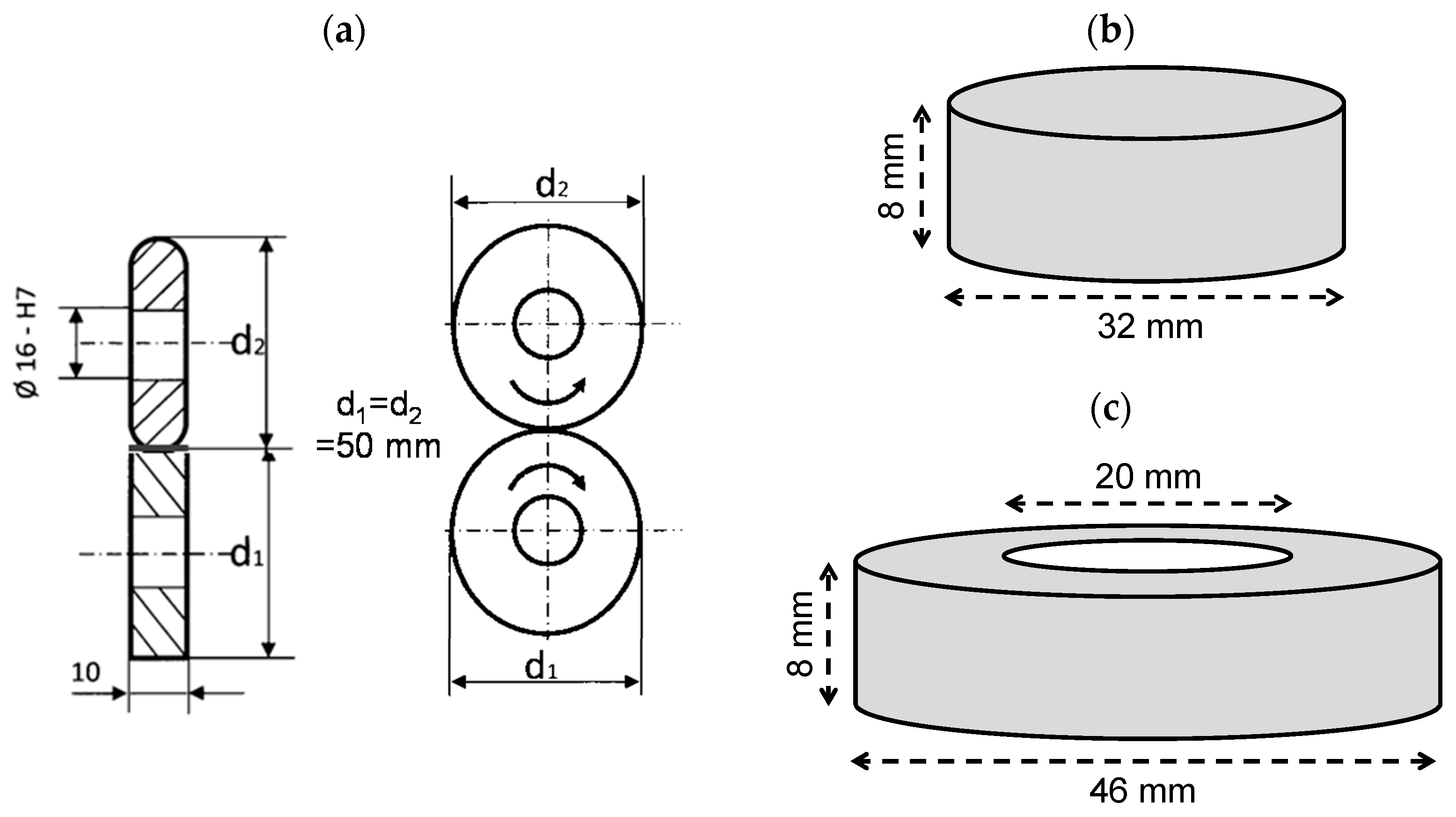
2.3. Model Wear Tests

The wear behavior was investigated by model wear tests and under industrial forging conditions. A combination of abrasion and Hertzian stress was realized by the two-disc test. The ball-on-disk test focused the adhesion and the tribooxidation. The thermal fatigue behavior was investigated by cyclic induction heating and quenching. In the model wear tests, carbonitrided and tempered as well as carbonitrided and nitrided specimens were compared to quenched and tempered and nitrided specimens. For further description of the experimental setup, see [15].

2.4. Forging Tests

In order to investigate the wear behaviour under practical conditions, the treatment combination of carbonitring and nitriding was transferred to forging dies. The experimental dies were used at two forges in the serial production. Low-alloy steels were formed in each case at a temperature >1200 °C. The cycle time was 10–15 s. A graphite-free salt (white lubricant) was used as a lubricant. The lifetime of the carbonitrided and nitrided dies were compared with those in the relevant series tools.

3. Results and Discussion

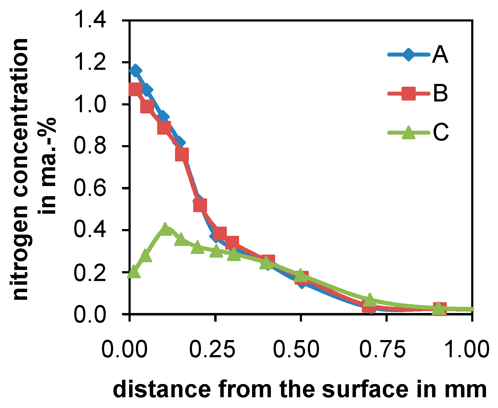
3.1. Carbonitriding Treatment

The usual hardening temperature of X38CrMoV5-3 is 1030–1080 °C, whereas the carbonitriding treatment is usually carried out at 850–950 °C. The high hardening temperature is necessary in order to bring the alloying elements in solution for the secondary hardening during tempering. An increase in the carbonitriding temperature is limited by the increasing ammonia decomposition at higher temperatures. Table 1 shows the results from carbonitriding experiments at different temperatures. As the measured variable for the ammonia concentration, a residual ammonia amount of 3500 ppm in the exhaust gas was targeted. It is obvious that this ammonia amount could not be reached at temperatures above 850 °C due to the increasing decomposition of ammonia.
The smaller amount of ammonia that was not thermally decomposed also led to a smaller nitrogen concentration in the material. However, since nitrogen diffusion is faster at higher temperatures, the treatment temperature should not be chosen too low. As the best compromise regarding a high nitrogen concentration in the surface zone and a high diffusion depth, the temperature 950 °C was chosen for the carbonitriding treatments. Since the aim of the carbonitriding is the diffusion of nitrogen into the surface layer, the carbon potential was chosen to match the material’s carbon content. The chosen carbon potential also includes the influence of the alloying elements on the equilibrium concentration [16].
The full parameters for the heat treatments are given in Table 2. The processing of carbonitriding was done with three methods. The first process (A) was a direct hardening at carbonitriding temperature where the core was hardened at too low a temperature. The second process (B) was a two-stage carbonitriding where the temperature was increased for the hardening step after carbonitriding followed by an oil quenching. The hardening temperature in this process was limited to 1000 °C by the equipment. The third carbonitriding treatment (C) was followed by a separate vacuum hardening where a sufficient hardening temperature for the material could be realized.

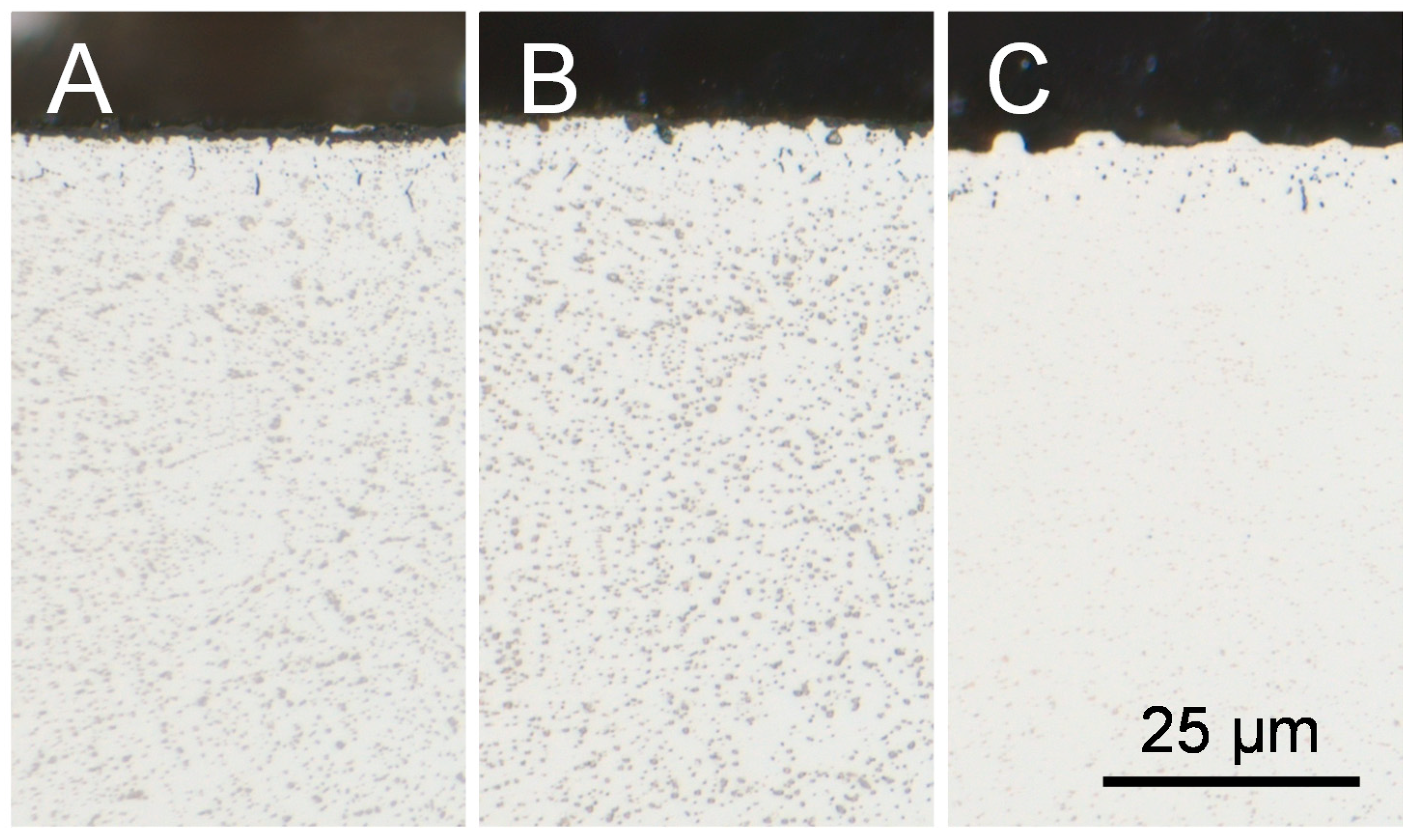
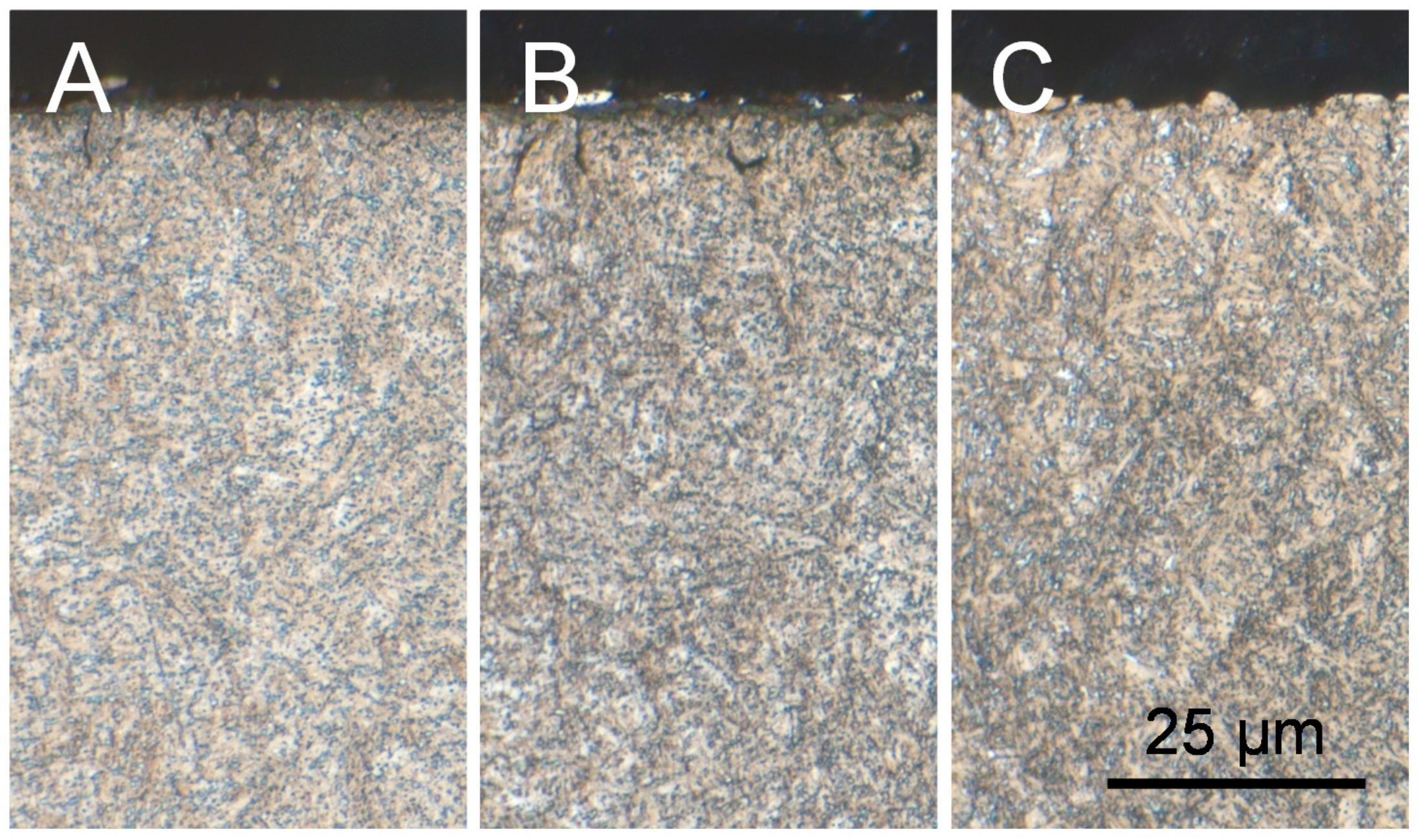
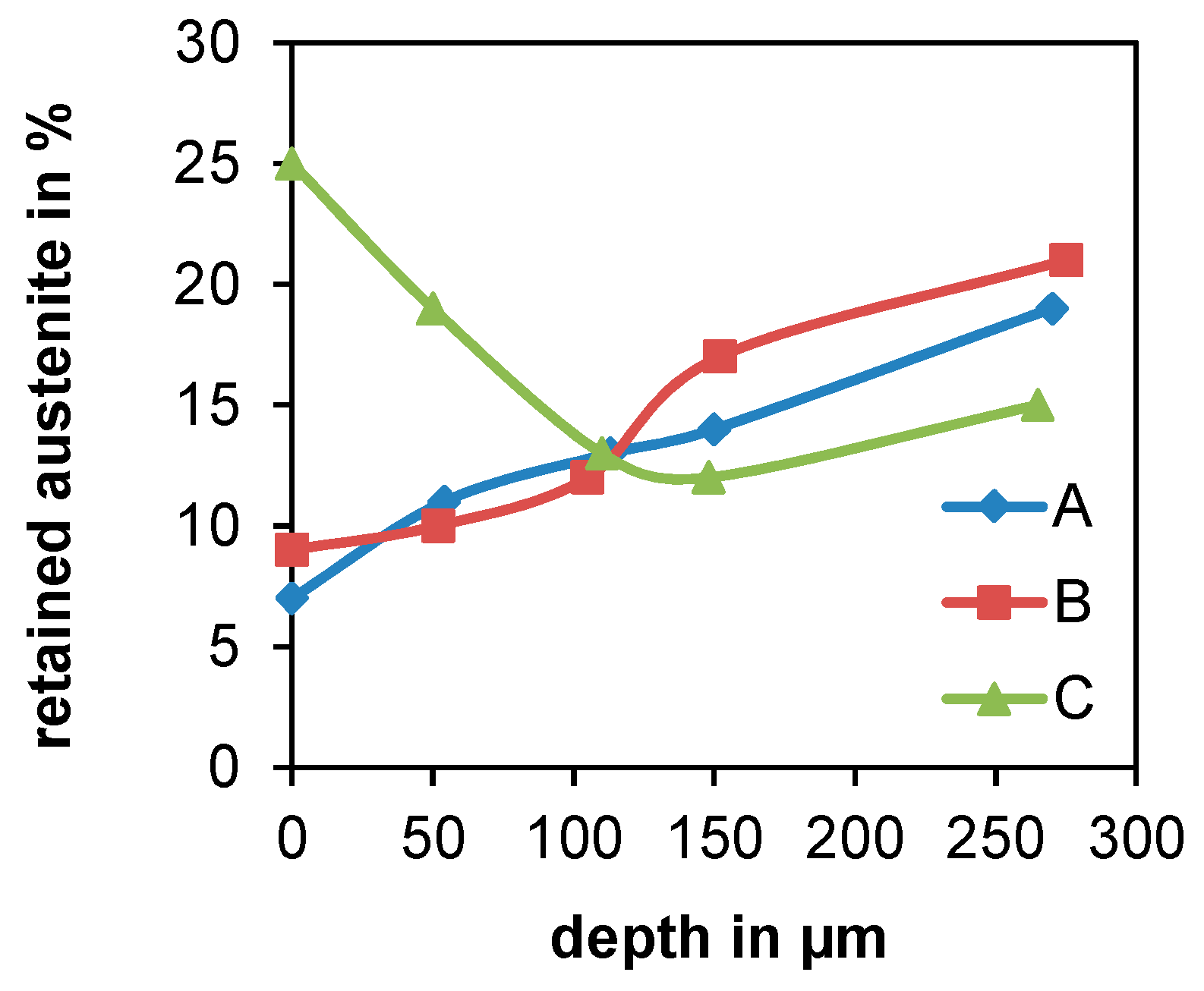
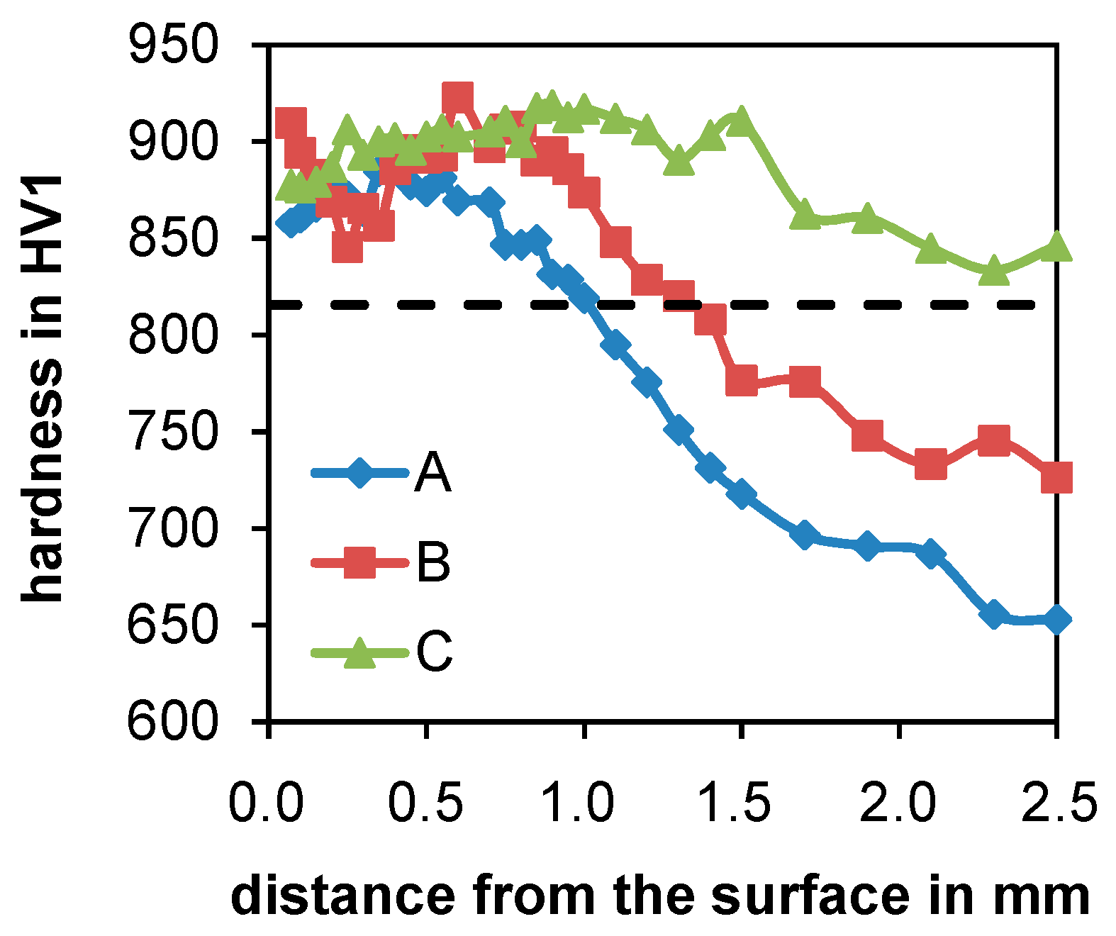
3.2. Microstructure of the Carbonitrided Layers
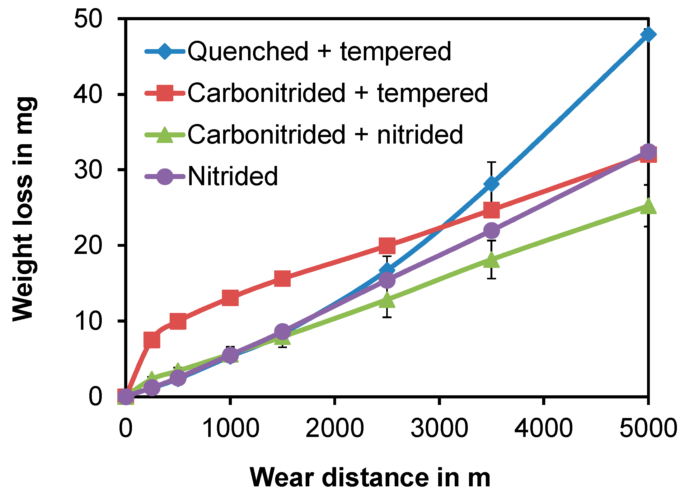
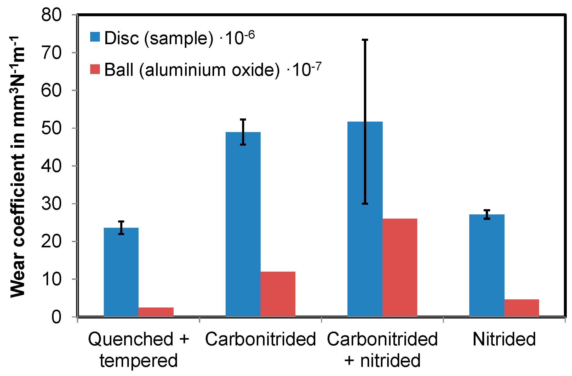
Figure 2 shows the nitrogen profiles after the three carbonitriding treatments with different processing. Due to the same treatment temperature and time of the carbonitriding step, the nitrogen profiles of heat treatments A and B were similar. The additional hardening step of 0.5 h at 1000 °C did not lead to a higher diffusion depth because, at this temperature, most of the ammonia decomposes (see Table 1), and only a small amount of nitrogen is taken by the material (see Figure 2). A different nitrogen profile could be observed after treatment C where a typical vacuum hardening was added after carbonitriding and quenching. During the vacuum treatment, an effusion of nitrogen occurred, and the nitrogen content in the carbonitrided layer decreased.
The unetched cross sections in Figure 3 show the different distribution of the carbonitrides in the surface region after the three processing variants. The carbonitride distributions after treatments A and B were very similar. The additional processing step at 1000 °C was not high enough to solve the carbonitrides in specimen B. Instead, they were slightly coarsened. In specimen C, there were not any visible carbonitrides. They were dissolved at the higher hardening temperature of 1050 °C.
Figure 4 shows the cross sections of the three processing variants etched with Nital. Despite the different hardening temperatures 950 °C (A), 1000 °C (B), and 1050 °C (C), the oxidation of the surface near the region was similar after the different treatments.
Due to the fact that nitrogen stabilizes the austenitic phase, retained austenite was expected in the surface region. Figure 5 shows the amount of retained austenite in the nitrogen-rich surface layer detected by X-ray diffraction. The treatment variant C had the highest amount of retained austenite at the surface, although the nitrogen content was significantly lower than the one of the two other treatments. This is due to the fact that the carbonitrides were dissolved during the hardening step at 1050 °C, and the nitrogen in the solution was higher than after treatments A and B where the most nitrogen was bonded in carbonitrides and therefore had no effect on the austenite stabilization.
The hardness of the carbonitrided layers is shown in Figure 6. The dashed line is the average hardness of a specimen that was only vacuum hardened and oil quenched. The hardness of the carbonitrided layer that had a thickness of approx. 0.7–0.8 mm (according to the nitrogen profiles) was similar after the different processing and in all three cases higher than the conventional hardened specimen. Beneath the carbonitrided layer, the influence of the different hardening temperatures can be observed. The hardening temperature of treatments A and B was too low. The hardness of the vacuum-hardened specimen could not be reached. Only treatment C, in which the hardening step was identical to the reference treatment, led to the same hardness of the uncarbonitrided material.

3.3. Wear Behavior

In the model wear tests, carbonitrided and tempered as well as carbonitrided and nitrided specimens were compared to quenched as well as tempered and nitrided specimens. The carbonitriding was carried out as a two-stage treatment with an austenitization temperature of 1000 °C directly after carbonitriding was chosen.

3.3.1. Two-Disc Test

In the two-disc test, the weight loss during the experiment was detected as a criterion for wear. Figure 7 shows the weight loss of the heat treatment variants dependent on the wear distance. The quenched and tempered condition showed by far the greatest loss of mass under the experimental conditions. At the beginning of the experiment, the specimens wore relatively little until a wear distance of appr. 1500 m. Then, the weight loss increased drastically.
The lowest total loss of mass was observed on the carbonitrided and nitrided specimen. The weight loss was also at its lowest at the beginning of the experiment and increased almost linearly along the wear distance.
The total weight loss of the carbonitrided and tempered specimen was similar to the one of the nitrided specimen, but these specimens showed a very different development of wear. In the nitrided state, the mass loss was also slight at the beginning and increased substantially after a wear distance of approx. 1500 m. The carbonitrided and tempered specimen wore faster at the beginning of the experiment. After approx. 250 m of wear distance, the wear slowed down and then increased continually until the end of the experiment.

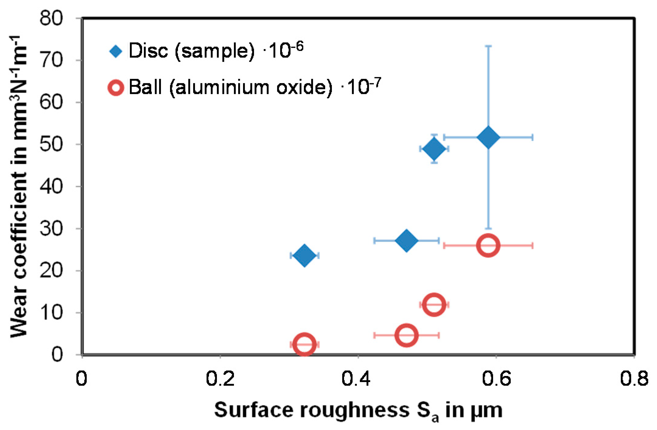
3.3.2. Ball-on-Disc Test

In the ball-on-disc test, the wear coefficients were determined based on the wear marks on the specimen and the ball (Al2O3). Figure 8 shows the wear coefficients that were obtained in this way. It is striking that the carbonitrided specimen as well as the carbonitrided and nitrided specimen had the highest wear coefficients. However, there was also an influence on the surface roughness of the specimens, which was different due to the different heat treatments. Figure 9 shows a clear connection between the wear coefficients and the roughness of the specimen surfaces: the wear coefficient rises as the roughness of the specimen surfaces increases.

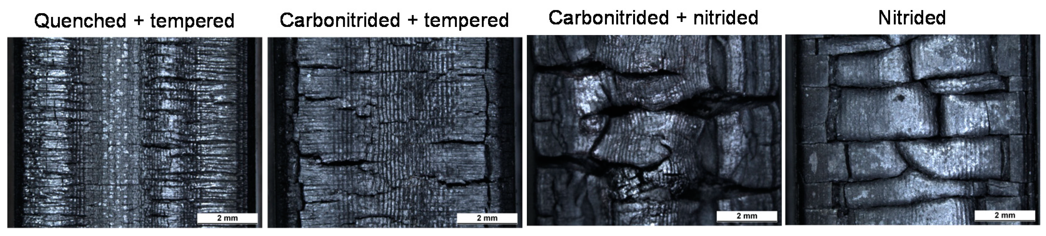
3.3.3. Thermal Fatigue Behavior

The thermal fatigue behavior was investigated by cyclic induction heating and quenching. Figure 10 shows the specimens’ surfaces of the differently heat-treated material X38CrMoV5-3 (quenched + tempered, nitrided, carbonitrided + tempered, and carbonitrided + nitrided), each after 100 load cycles. Already at first glance, a different risk network can be recognized. In the hardened condition, the cracks were fine and numerous, while a substantially coarser network of cracks was formed in the nitrided condition. The condition of the surface on the carbonitrided and tempered specimens looked similar to the hardened specimen, but the cracks were somewhat larger here. In the carbonitrided and nitrided specimens, the network of cracks looked similar to the specimens that were only nitrided with finer cracks between the coarser network of cracks.
It was suspected that there is a relation between the nitrogen content in the surface layer and the cracking behavior. Table 3 shows the surface near nitrogen content measured by GDOES. Because of the mere thermal treatment, there was almost no nitrogen in the surface area of the quenched and tempered specimen. After carbonitriding and tempering, the nitrogen concentration was 0.8 ma.%. A significantly higher nitrogen concentration in the surface layer was found for the samples where the last heat treatment step was nitriding. The nitrogen contents of the carbonitrided and nitrided and the exclusively nitrided specimen were similar at appr. 9 ma.%.
During service, the surface zone of forging dies is heated up. Depending on the temperature and the material phase, transformations can take place under thermal load. The element nitrogen stabilizes the austenitic phase by lowering theAC1 temperature [15]. This means that surface areas with a higher nitrogen content will form austenite at lower temperatures than surfaces with lower nitrogen content. This leads to different stress conditions and finally to different crack formations.
The retained austenite after one cycle of induction heating and quenching was detected by X-ray analysis (Table 4). In the variants “carbonitrided + nitrided” and “nitrided,” retained austenite was actually detected because the austenite was unable to transform completely into martensite during quenching due to the high nitrogen content.
However, not only the phase transformations have an influence on the stress condition and therefore on the cracking behavior. Another reason is the increasing formation of nitride precipitations with increasing nitrogen content. The alloying element nitrides are more heat resistant than the corresponding carbides and remain at elevated surface area temperatures. This can also cause a different stress condition in the surface area.

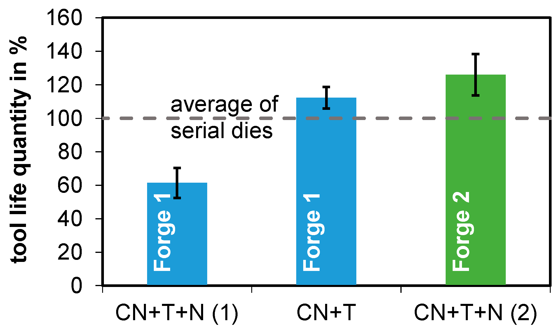
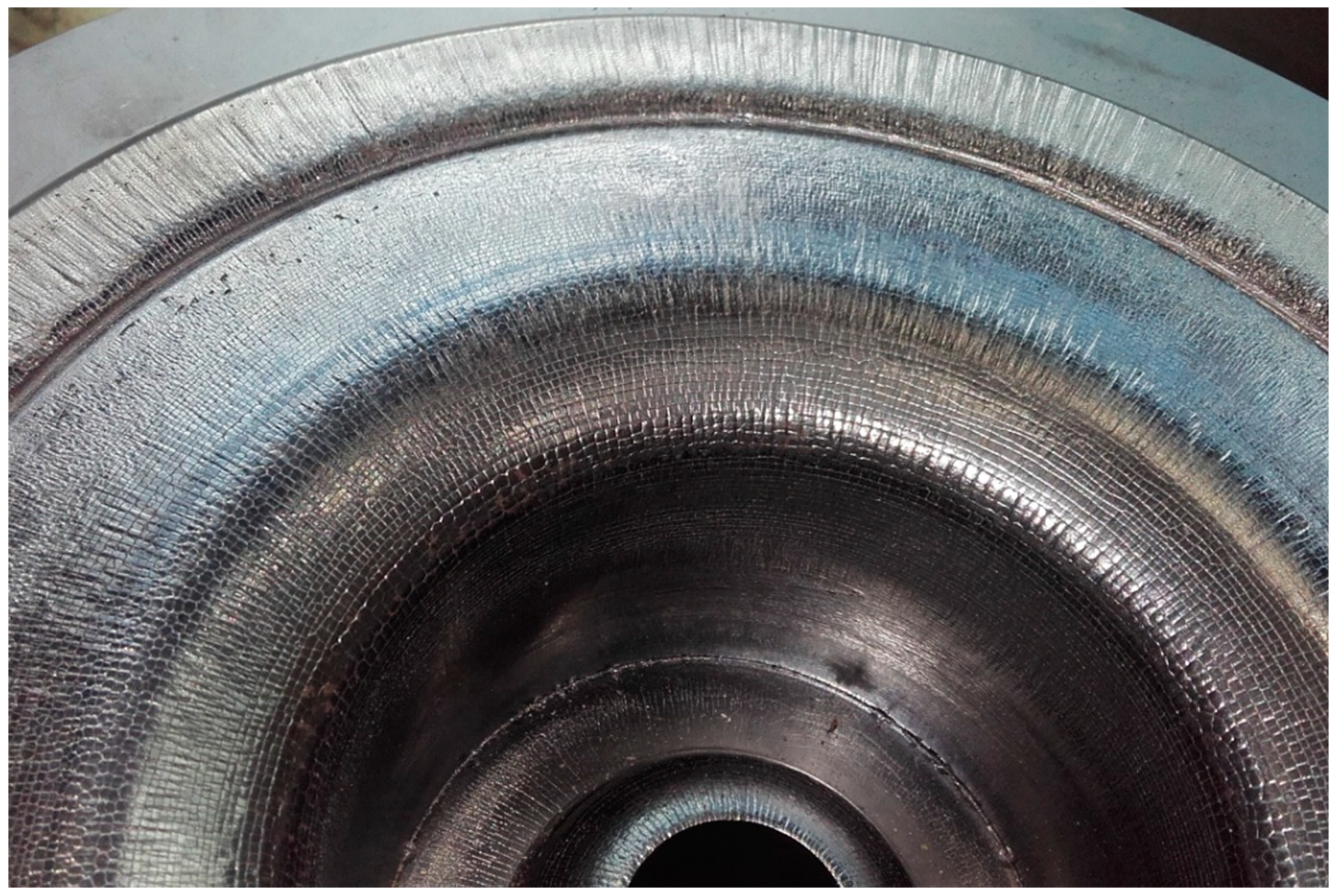
3.4. Tool Life Quantities

For the forging tests, forging dies were specially heat-treated (Table 5). The dies of forge 1 were carbonitrided and tempered in a two-stage process at 950 °C and 1000 °C. Additionally, some of the dies were nitrided subsequent to carbonitriding and tempering. The dies of forge 2 were carbonitrided and tempered in a two-stage process at 850 °C and 1000 °C and then nitrided.
The experimental dies were used in the forges until the lifespan was reached. Figure 11 shows the lifespans achieved by the tools with regard to series life. In forge 1, similar lifespans were achieved with the carbonitrided and tempered tools as with the series tools. The carbonitrided and nitrided tools had a lower tool life quantity than the serial tools.
However, a not inconsiderable proportion of the test tools were not removed due to wear but because of cracks and fractures, which made it impossible to use them up to the wear limit. These tools were not included in the evaluation.
It is assumed that the greater core hardness and the associated lower toughness of the tool base material was the cause of the high susceptibility to fracture. The hardness of the experimental tools was set to (50 + 2) HRC (approx. 560 HV1) following previous investigations [6], whereas the series tools were quenched and tempered to (48 + 2) HRC.
In comparison with the serial dies in forge 2, substantially greater lifespans were achieved with the experimental dies. However, it must be taken into account that the series tools in this case were only quenched and tempered and that an increase in lifespan would probably be possible through conventional nitriding too. Figure 12 shows a worn die from forge 2. Although the cracking network on the surface is clearly visible, the lifetime was higher than the one of the serial dies.

4. Conclusions

The wear resistance of forging dies can be improved by carbonitriding. In order to produce a sufficiently deep surface layer hardened with nitride precipitates and at the same time achieve sufficient core strength, the heat treatment must be adapted to the die material. A two-stage carbonitriding and hardening process is necessary for the hot working steel X38CrMoV5-3 because at the hardening temperature of this material, the nitrogen source NH3 is not stable enough to realize a sufficient nitrogen amount in the surface layer. Experiments at different temperatures showed that the ammonia content in the carbonitriding atmosphere decreases at temperatures of 900 °C and higher. In addition, the nitrogen content in the surface region of the carbonitrided material decreases too. Therefore it is not possible to do a direct hardening from the carbonitriding temperature for the hot working steel X38CrMoV5 3. The two stages of carbonitriding and hardening can be carried out in different orders, but the order influences the microstructure and the hardness of the carbonitrided layer as well as of the core material.
The wear properties of the different surface-treated specimens were evaluated using model tests and life tests on forging dies. In the two-disc test, the carbonitrided and nitrided variants showed the lowest wear. In the ball-on-disc test, the carbonitrided specimens exhibited the highest wear coefficients, but this was attributable to the higher surface roughness of the specimens. The thermal-fatigue tests showed that different thermal crack networks are formed on the surface depending on the nitrogen content of the X38CrMoV5-3 material, because the transformation process and the precipitation state of the surface change.
In the service life tests, similar tool life quantities could be achieved with the carbonitrided and nitrided experimental dies as with conventionally nitrided dies. Compared with quenched and tempered serial dies, the tool life could be significantly increased with carbonitriding and nitriding of the tools. The only carbonitrided and tempered dies also had higher tool life quantities than the serial dies, so subsequent nitriding treatment is not mandatory.
Since carbonitriding can be carried out together with hardening and since subsequent nitriding is not mandatory, the change from nitrided to carbonitrided dies can shorten the process chain and thus save time and costs. Restricting factors are the dimensional and shape changes that occur during carbonitriding. Carbonitriding is therefore only suitable for (pre-)forging dies with high tolerances, since the carbonitriding layer can only be reworked to a limited extent. It is essential to take the dimensional and shape changes into account when designing the dies or to use (pre-)forging dies with correspondingly high tolerance ranges.

Author Contributions

S.H.: project administration, conceptualization, investigation, methodology, writing—original draft preparation; H.K.-W.: funding acquisition, supervision, writing—review and editing; M.S.: funding acquisition, supervision, writing—review and editing. All authors have read and agreed to the published version of the manuscript.

Funding

The authors gratefully acknowledge support from the Forschungsgesellschaft Stahlverformung e. V. The project IGF 18394 N was funded by the AiF (Arbeitsgemeinschaft industrieller Forschungsvereinigungen „Otto von Guericke“ e. V.) trough financial ressources from the BMWi (Bundesministerium für Wirtschaft und Energie).

Institutional Review Board Statement

Not applicable.

Informed Consent Statement

Not applicable.

Data Availability Statement

Data sharing is not applicable to this article.

Conflicts of Interest

The authors declare no conflict of interest. The funders had no role in the design of the study, in the writing of the manuscript, and in the decision to publish the results.

References

  1. Luig, H.; Bobke, T. Beanspruchung und Schadensarten an Schmiedegesenken. Tribol. Und Schmier. 1990, 37, 76–81. [Google Scholar]
  2. Spies, H.-J. Kontrolliertes Gasnitrieren von Eisenwerkstoffen. Stahl 1992, 2, 77. [Google Scholar]
  3. Spies, H.-J.; Zimdars, H.; Müller, C. Erfahrungen beim Gasoxinitrieren von Werkzeugen für die Warmumformung; Meform: Freiberg, Germany, 2012. [Google Scholar]
  4. Spies, H.-J.; Berns, H.; Ludwig, A.; Bambauer, K.; Brusky, U. Warmhärte und Eigenspannungen nitrierter Stähle. HTM Härterei-Techn. Mitt. 1998, 53, 359–366. [Google Scholar]
  5. Klümper-Westkamp, H. Load-adapted nitriding and nitrocarburising of forging dies for hot massive forming of steel. In Proceedings of the European Conference on Heat Treatment 2010 Nitriding and Nitrocarburising, Aachen, Germany, 29–30 April 2010. [Google Scholar]
  6. Hoja, S. Schmiedegerecht Nitrierte Gesenke. Ph.D. Thesis, University of Bremen, Bremen, Germany, 2017. [Google Scholar]
  7. Macherauch, E.; Kloos, K.H. Bewertung von Eigenspannungen. Eigenspannungen und Lastspannungen. Beih. HTM—Härterei-Techn. Mitt. 1982, 28, 175–194. [Google Scholar]
  8. Somers, M.A.J. Verbindungsschichtbildung beim Nitrieren und Nitrocarburieren—Wissensstand und zukünftiger Forschungsbedarf. HTM J. Heat Treatm. Mat. 2011, 66, 2. [Google Scholar] [CrossRef]
  9. Winter, K.-M.; Hoja, S.; Klümper-Westkamp, H. Controlled Nitriding and Nitrocarburizing—State of the Art. In Proceedings of the European Conference on Heat Treatment 2010 Nitriding and Nitrocarburising, Aachen, Germany, 29–30 April 2010. [Google Scholar]
  10. Hoja, S.; Klümper-Westkamp, H.; Hoffmann, F.; Zoch, H.-W.; Baumgartner, N.; Weidel, S. Schmiedegerecht nitrierte Gesenke. Schmiede J. 2013, 32–35. [Google Scholar]
  11. Lombardo, S.; Steinbacher, M. Carbonitrieren von verzahnten Getriebebauteilen; FVA 513 I, Heft 970; Forschungsvereinigung Antriebstechnik e.V.: Frankfurt, Germany, 2011. [Google Scholar]
  12. Meinhard, E. Carbonitrieren—Warum und wie? Tech. Z. Für Met. 1982, 10, 2–8. [Google Scholar]
  13. Jasinski, J.; Torbus, R.; Jeziorski, L. Influence of the microstructure modification on surface layer of X37CrMoV5-1 steel after carbonitriding process. 2nd Int. Conf. In Heat Treatment and Surface Engineering in Automotive Applications; Associazione Italiana die Metallurgia: Riva del Garda, Italy, 2005. [Google Scholar]
  14. Jasinski, J.; Torbus, R.; Kasprzycka, E.; Bogdanski, B. Influence of the preheat treatment on the microstructure and properties of X37CrMoV5-1 steel. Steel. Mater. Manuf. Process. 2007, 22, 5–8. [Google Scholar] [CrossRef]
  15. Hoja, S.; Klümper-Westkamp, H.; Hasselbruch, H.; Skalecki, M.G.; Steinbacher, M.; Zoch, H.-W. Verschleißverhalten carbonitrierter und nitrierter Warmarbeitsstähle. HTM J. Heat Treatm. Mat. 2018, 73, 211–222. [Google Scholar] [CrossRef]
  16. Hoja, S.; Skalecki, M.G.; Klümper-Westkamp, H.; Steinbacher, M.; Zoch, H.-W. Carbonitrieren von warmarbeitsstählen. HTM J. Heat Treatm. Mat. 2017, 72, 187–198. [Google Scholar] [CrossRef]
Figure 1. Geometry of the specimens for the model wear tests. (a) Two-disc test. (b) Ball-on-disc test. (c) Thermal fatigue test.
Metals 11 01651 g001
Figure 2. Nitrogen profiles after carbonitriding of the material X38CrMoV5-3 with different process management (for heat treatment parameters of A, B and C see Table 2).
Metals 11 01651 g002
Figure 3. Unetched cross sections of the material X38CrMoV5-3 after the carbonitriding treatments (for heat treatment parameters of (AC) see Table 2).
Metals 11 01651 g003
Figure 4. Cross sections of the material X38CrMoV5-3 after the carbonitriding treatments etched with Nital (for heat treatment parameters of (AC) see Table 2).
Metals 11 01651 g004
Figure 5. Retained austenite in the nitrogen-rich surface layers (for heat treatment parameters of A, B and C see Table 2).
Metals 11 01651 g005
Figure 6. Hardness profiles after carbonitriding of the material X38CrMoV5-3 with different process management (for heat treatment parameters of A, B and C see Table 2).
Metals 11 01651 g006
Figure 7. Weight loss of the different heat-treated specimens in the two-disc test dependent on the wear distance.
Metals 11 01651 g007
Figure 8. Wear coefficient from ball-on-disc test for the different heat-treated specimens.
Metals 11 01651 g008
Figure 9. Wear coefficient from ball-on-disc test dependent on the surface roughness.
Metals 11 01651 g009
Figure 10. Surface of the different heat-treated specimens after 100 cycles of induction heating and quenching.
Metals 11 01651 g010
Figure 11. Tool life quantities of the carbonitrided and tempered (and nitrided) dies.
Metals 11 01651 g011
Figure 12. Forging die of forge 2 after use.
Metals 11 01651 g012
Table 1. Measured NH3 concentration during carbonitriding in the Solo system for 8 h with CP = 0.6% and a target residual ammonia concentration of 3500 ppm at different temperatures and resulting nitrogen concentration at the surface of the material X38CrMoV5-3.
T in °C8008509009501000
Res. NH3 in ppm350035002000800300
Nitrogen concentration in ma. %1.711.761.471.260.18
Table 2. Heat treatment parameters for the carbonitriding of the material X38CrMoV5-3.
No.Heat Treatment
A950 °C 8 h CP = 0.35% NH3 = max./oil
B950 °C 8 h CP = 0.35% NH3 = max./
1000 °C 0.5 h CP = 0.35% NH3 = max./oil
C950 °C 8 h CP = 0.35% NH3 = max./oil
1050 °C 1 h vacuum/oil
Table 3. Nitrogen content of the specimens for the thermal fatigue investigations in the depth of 1 µm.
Heat TreatmentNitrogen Content
in ma.%
Quenched + tempered<0.1
Carbonitrided + tempered0.8
Carbonitrided + nitrided9.2
Nitrided8.8
Table 4. Retained austenite in the surface area after one cycle of induction heating and quenching.
Heat TreatmentRetained
Austenite in %
Quenched + tempered0
Carbonitrided + tempered0
Carbonitrided + nitrided37
Nitrided59
Table 5. Heat treatment parameters for the experimental forging dies.
Heat Treatment VariantCarbonitriding
(CN)
CP = 0.35% NH3 = max.
Tempering
(T)
Nitriding
(N)
CN + T950 °C 8 h,
1000 °C 1 h
3× 560 °C 2 h-
CN + T + N (1)950 °C 8 h,
1000 °C 1 h
3× 560 °C 2 h520 °C 24 h KN = 3
CN + T + N (2)850 °C 32 h,
1000 °C 1 h
3× 560 °C 2 h520 °C 24 h KN = 3
Publisher’s Note: MDPI stays neutral with regard to jurisdictional claims in published maps and institutional affiliations.

