
Manufacturing of Tool Steels by PBF-EB

Abstract
:1. Introduction
2. Materials and Methods
3. Results
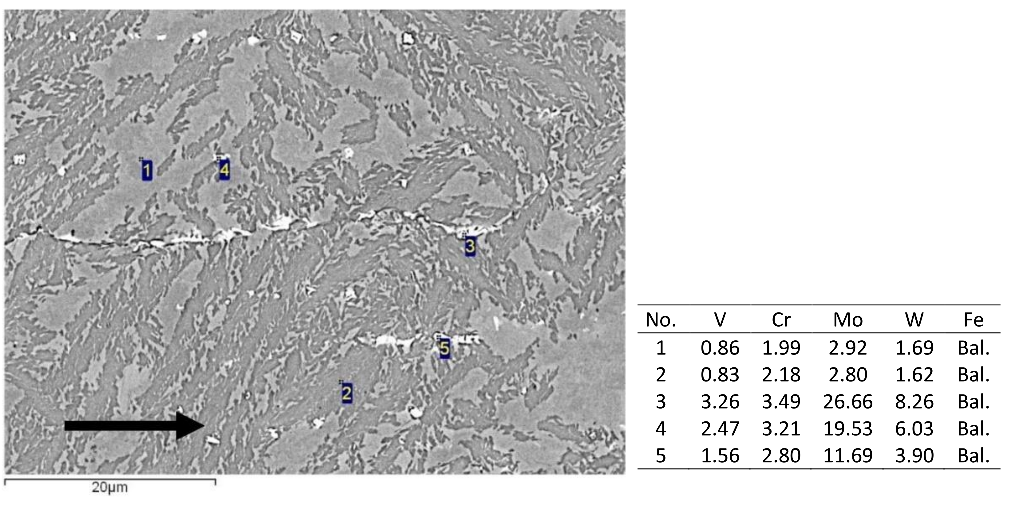
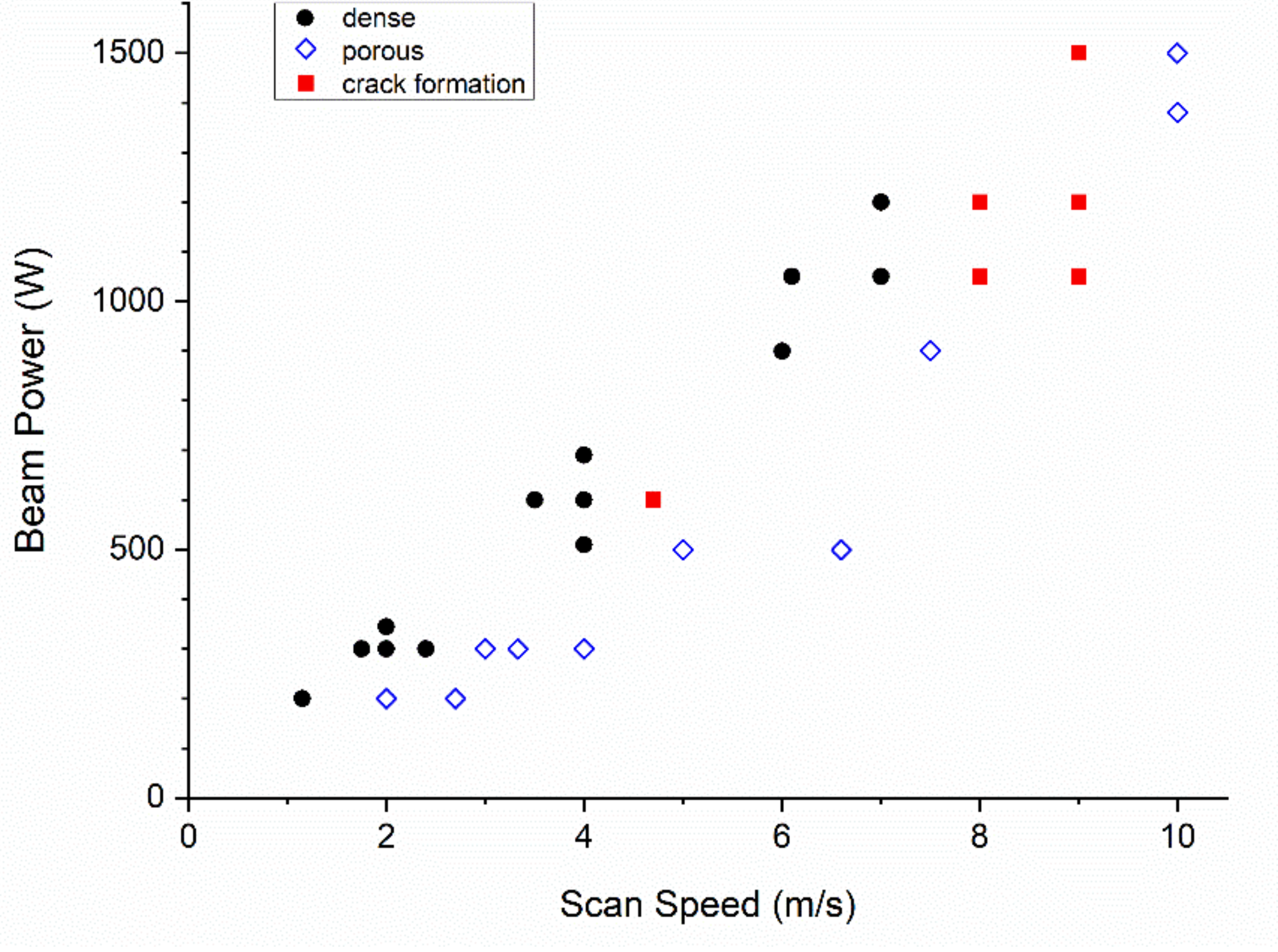
3.1. X65MoCrWV3-2
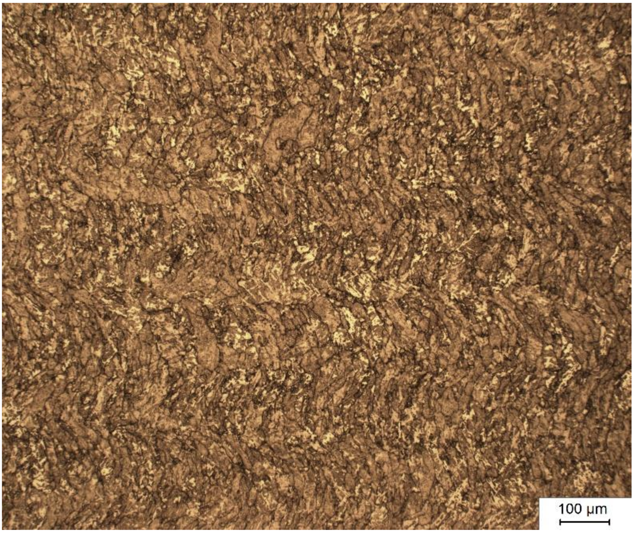
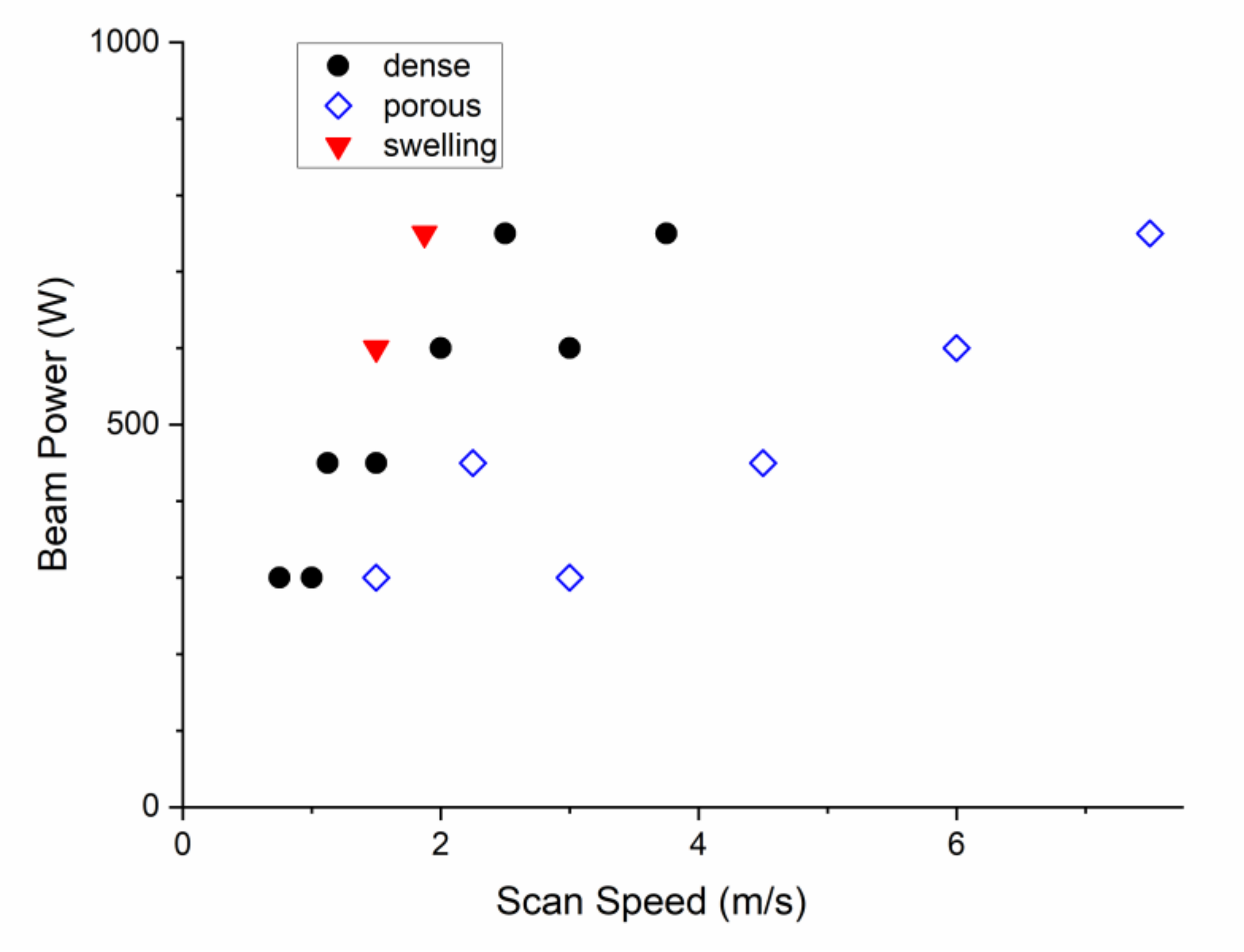
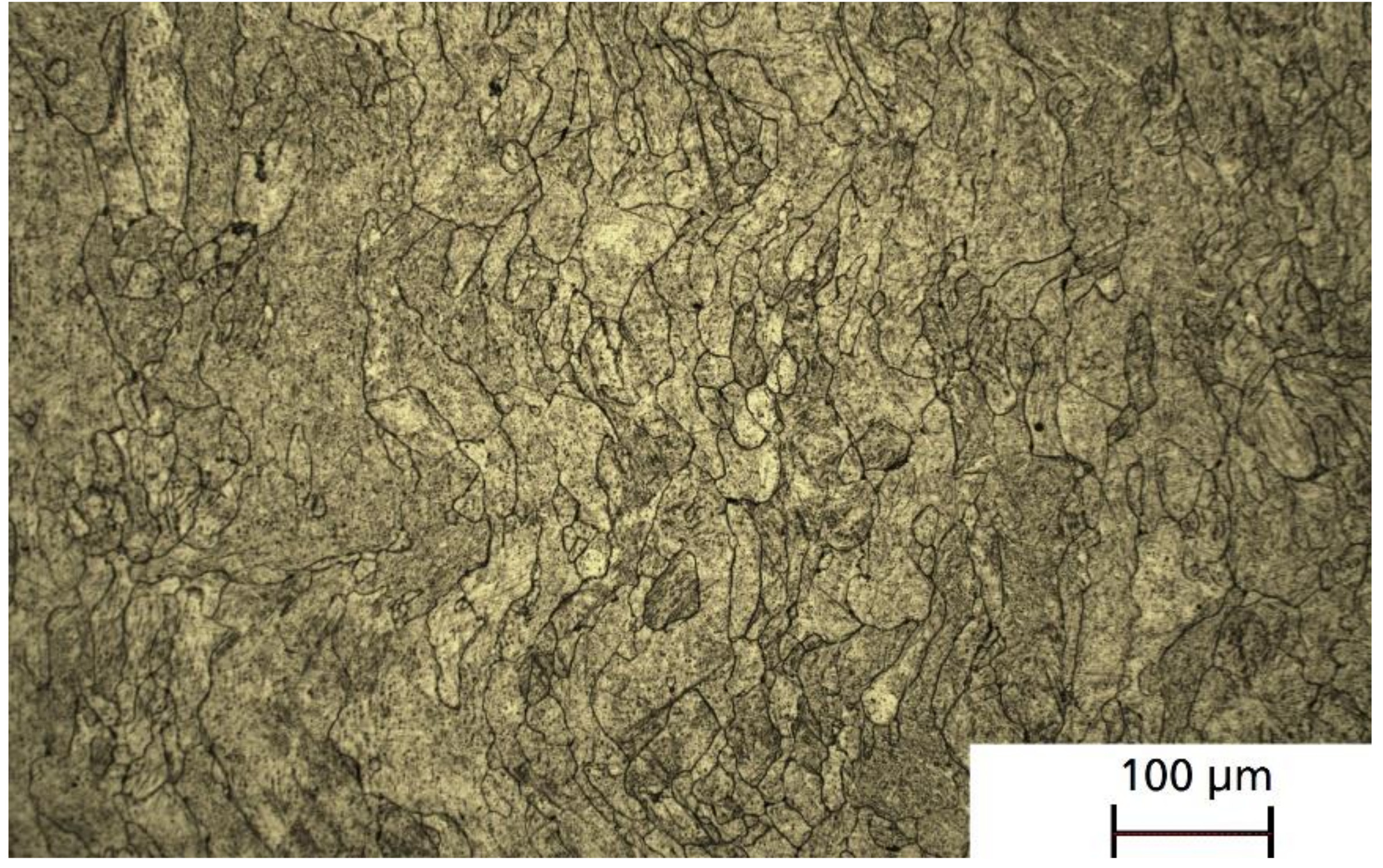
3.2. X37CrMoV5-1
4. Discussion
4.1. X65MoCrWV3-2
4.2. X37CrMoV5-1
5. Conclusions
- For X65MoCrWV3-2 a narrow process window for the fabrication of dense, crack-free parts exists. At 50 µm hatch distance this corresponds to a volumetric energy density of ~50 J/mm3.
- Higher scan speeds and hatch distances result in crack formation.
- In PBF-EB X37CrMoV5-1 no cracks were detected. Therefore, a wider range of scan speeds and hatch distances can be applied.
- No significant increase in impurities was detected after the PBF-EB process. In addition, the alloy composition did not change.
- The as-built microstructure is fine-grained and free of martensite.
Author Contributions
Funding
Institutional Review Board Statement
Data Availability Statement
Acknowledgments
Conflicts of Interest
References
- Mezghani, A.; Nassar, A.R.; Dickman, C.J.; Valdes, E.; Alvarado, R. Laser powder bed fusion additive manufacturing of copper wicking structures: Fabrication and capillary characterization. Rapid Prototyp. J. 2021, 27, 1181–1188. [Google Scholar] [CrossRef]
- DebRoy, T.; Wei, H.L.; Zuback, J.S.; Mukherjee, T.; Elmer, J.W.; Milewski, J.O.; Beese, A.M.; Wilson-Heid, A.; De, A.; Zhang, W. Additive manufacturing of metallic components—Process, structure and properties. Prog. Mater. Sci. 2018, 92, 112–224. [Google Scholar] [CrossRef]
- Kempen, K.; Vrancken, B.; Buls, S.; Thijs, L.; van Humbeeck, J.; Kruth, J.-P. Selective laser melting of crack-free high density M2 high speed steel parts by baseplate preheating. J. Manuf. Sci. Eng. 2014, 136, 61026. [Google Scholar] [CrossRef]
- Kumar, M.; Gibbons, G.J.; Das, A.; Manna, I.; Tanner, D.; Kotadia, H.R. Additive manufacturing of aluminium alloy 2024 by laser powder bed fusion: Microstructural evolution, defects and mechanical properties. Rapid Prototyp. J. 2021, 27, 1388–1397. [Google Scholar] [CrossRef]
- Magana Carranza, R.; Robinson, J.; Ashton, I.; Fox, P.; Sutcliffe, C.; Patterson, E. A novel device for in-situ force measurements during laser powder bed fusion (L-PBF). Rapid Prototyp. J. 2021, 27, 1423–1431. [Google Scholar] [CrossRef]
- Sander, J.; Hufenbach, J.K.; Giebeler, L.; Wendrock, H.; Kühn, U.; Eckert, J. Microstructure and properties of FeCrMoVC tool steel produced by selective laser melting. Mater. Des. 2016, 89, 335–341. [Google Scholar] [CrossRef]
- Kruth, J.-P. Part and material properties in selective laser melting of metals. In Proceedings of the 16th International Symposium on Electromachining, Shanghai, China, 14 April 2010; pp. 3–14. [Google Scholar]
- Krell, J.; Röttger, A.; Geenen, K.; Theisen, W. General investigations on processing tool steel X40CrMoV5-1 with selective laser melting. J. Mater. Process. Technol. 2018, 255, 679–688. [Google Scholar] [CrossRef]
- Simson, T.; Koch, J.; Rosenthal, J.; Kepka, M.; Zetek, M.; Zetkova, I.; Wolf, G.; Tomcik, P.; Kulhanek, J. Mechanical Properties of 18Ni-300 maraging steel manufactured by LPBF. Procedia Struct. Integr. 2019, 17, 843–849. [Google Scholar] [CrossRef]
- Mooney, B.; Kourousis, K.I. A review of factors affecting the mechanical properties of maraging steel 300 fabricated via laser powder bed fusion. Metals 2020, 10, 1273. [Google Scholar] [CrossRef]
- Bajaj, P.; Hariharan, A.; Kini, A.; Kürnsteiner, P.; Raabe, D.; Jägle, E.A. Steels in additive manufacturing: A review of their microstructure and properties. Mater. Sci. Eng. A 2020, 772, 138633. [Google Scholar] [CrossRef]
- Haghdadi, N.; Laleh, M.; Moyle, M.; Primig, S. Additive manufacturing of steels: A review of achievements and challenges. J. Mater. Sci. 2021, 56, 64–107. [Google Scholar] [CrossRef]
- Wang, J.; Liu, S.; Fang, Y.; He, Z. A short review on selective laser melting of H13 steel. Int. J. Adv. Manuf. Technol. 2020, 108, 2453–2466. [Google Scholar] [CrossRef]
- Mertens, R.; Vrancken, B.; Holmstock, N.; Kinds, Y.; Kruth, J.-P.; Van Humbeeck, J. Influence of powder bed preheating on microstructure and mechanical properties of H13 tool steel SLM parts. Phys. Procedia 2016, 83, 882–890. [Google Scholar] [CrossRef] [Green Version]
- Asberg, M.; Fredriksson, G.; Hatami, S.; Fredriksson, W.; Krakhmalev, P. Influence of post treatment on microstructure, porosity and mechanical properties of additive manufactured H13 tool steel. Mater. Sci. Eng. A 2019, 742, 584–589. [Google Scholar] [CrossRef]
- Cormier, D.; Harrysson, O.; West, H. Characterization of H13 steel produced via electron beam melting. Rapid Prototyp. J. 2004, 10, 35–41. [Google Scholar] [CrossRef]
- Rännar, L.E.; Glad, A.; Gustafson, C.G. Efficient cooling with tool inserts manufactured by electron beam melting. Rapid Prototyp. J. 2007, 13, 128–135. [Google Scholar] [CrossRef]
- Kahlert, M.; Brenne, F.; Vollmer, M.; Niendorf, T. Influence of microstructure and defects on mechanical properties of AISI H13 manufactured by electron beam powder bed fusion. J. Mater. Eng. Perform. 2021, 30, 6895–6904. [Google Scholar] [CrossRef]
- Casati, R.; Coduri, M.; Lecis, N.; Andrianopoli, C.; Vedani, M. Microstructure and mechanical behavior of hot-work tool steels processed by selective laser melting. Mater. Charact. 2018, 137, 50–57. [Google Scholar] [CrossRef]
- Huber, F.; Bischof, C.; Hentschel, O.; Heberle, J.; Zettl, J.; Nagulin, K.Y.; Schmidt, M. Laser beam melting and heat-treatment of 1.2343 (AISI H11) tool steel—Microstructure and mechanical properties. Mater. Sci. Eng. 2019, 742, 109–115. [Google Scholar] [CrossRef]
- Boes, J.; Röttger, A.; Mutke, C.; Escher, C.; Theisen, W. Microstructure and mechanical properties of X65MoCrWV3-2 cold-work tool steel produced by selective laser melting. Addit. Manuf. 2018, 23, 170–180. [Google Scholar] [CrossRef]
- Boes, J.; Röttger, A.; Theisen, W. Processing of X65MoCrWV3-2 cold work tool steel by laser powder bed fusion. Steel Res. Int. 2020, 91, 1900445. [Google Scholar] [CrossRef]
- Botero, C.; Ramsperger, M.; Selte, A.; Asvik, K.; Koptyug, A.; Skoglund, P.; Roos, S.; Rännar, L.-E.; Bäckström, M. Additive manufacturing of a cold-work tool steel using electron beam melting. Steel Res. Int. 2019, 91, 1900448. [Google Scholar] [CrossRef]
- Botero, C.A.; Selte, A.; Ramsperger, M.; Maistro, G.; Koptyug, A.; Bäckström, M.; Sjöström, W.; Rännar, L.-E. Microstructural and mechanical evaluation of a Cr-Mo-V cold-work tool steel produced via electron beam melting (EBM). Materials 2021, 14, 2963. [Google Scholar] [CrossRef] [PubMed]
- Liu, Z.H.; Zhang, D.Q.; Chua, C.K.; Leong, K.F. Crystal structure analysis of M2 high speed steel parts produced by selective laser melting. Mater. Charact. 2013, 84, 72–80. [Google Scholar] [CrossRef]
- He, Y.; Zhong, M.; Jones, N.; Beuth, J.; Webler, B. The columnar-to-equiaxed transition in melt pools during laser powder bed fusion of M2 steel. Metall. Mater. Trans. A 2021, 52, 4206–4221. [Google Scholar] [CrossRef]
- CP2M. Available online: https://www.doerrenberg.de/wp-content/uploads/2020/05/CP2M%C2%AE_en.pdf (accessed on 27 September 2021).
- Thermodur 2343. Available online: https://www.dew-stahl.com/fileadmin/files/dew-stahl.com/documents/Publikationen/Werkstoffdatenblaetter/Werkzeugstahl/Warmarbeitsstahl/GB_Thermodur2343.pdf (accessed on 27 September 2021).
- Jurisch, M.; Escher, C.; Kirchner, A.; Klöden, B.; Weißgärber, T.; Kieback, B. Processing of tool steels by Electron Beam Melting. In Fraunhofer Direct Digital Manufacturing Conference DDMC 2018 Proceedings; 2018; Available online: https://www.bookshop.fraunhofer.de/buch/Fraunhofer-Direct-Digital-Manufacturing-Conference-DDMC-2018/249002 (accessed on 11 October 2021).
- 1.2343—Werkstoff 1.2343 Datenblatt. Available online: https://www.stauberstahl.com/werkstoffe/12343-werkstoff-datenblatt/ (accessed on 9 August 2021).


| Dimension | Value |
|---|---|
| D10 | 63.6 µm |
| D50 | 93.5 µm |
| D90 | 166.8 µm |
| Apparent density | 4.12 ± 0.00 g/cm3 |
| Tap density | 4.72 ± 0.08 g/cm3 |
| Hall flow (50 g) | 18.5 ± 0.0 s |
| Carbon content | 0.6 wt-% |
| Dimension | Value |
|---|---|
| D10 | 65.6 µm |
| D50 | 89.4 µm |
| D90 | 141.1 µm |
| Apparent density | 4.11 ± 0.00 g/cm3 |
| Tap density | 4.76 ± 0.00 g/cm3 |
| Hall flow (50 g) | 17.1 ± 0.1 s |
| C | Cr | Mn | Mo | V | |
|---|---|---|---|---|---|
| Powder | 0.43 | 5.82 ± 0.03 | 0.72 ± 0.002 | 1.35 ± 0.01 | 0.46 ± 0.002 |
| PBF-EB material | 0.42 | 5.90 ± 0.02 | 0.66 ± 0.003 | 1.40 ± 0.01 | 0.46 ± 0.005 |
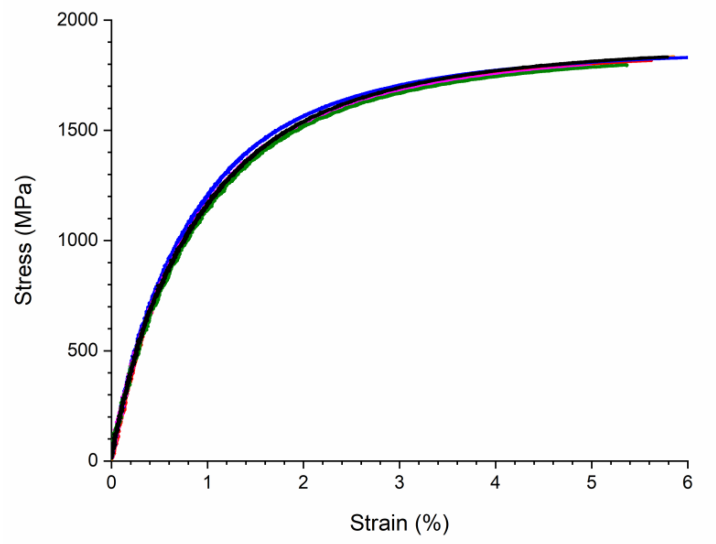
| E | YTS | UTS | A | |
|---|---|---|---|---|
| Z | 184 ± 4 GPa | 952 ± 7 MPa | 1796 ± 61 MPa | 4.5 ± 1.0% |
| X,Y | 185 ± 6 GPa | 937 ± 13 MPa | 1805 ± 22 MPa | 4.5 ± 0.5% |
| Quench-Hardened | 500 °C | 550 °C | 600 °C | |
| (HV 10) | 696 ± 12 | 689 ± 4 | 619 ± 3 | 470 ± 2 |
Publisher’s Note: MDPI stays neutral with regard to jurisdictional claims in published maps and institutional affiliations. |
© 2021 by the authors. Licensee MDPI, Basel, Switzerland. This article is an open access article distributed under the terms and conditions of the Creative Commons Attribution (CC BY) license (https://creativecommons.org/licenses/by/4.0/).
Share and Cite
Kirchner, A.; Klöden, B.; Franke-Jurisch, M.; Inarra Rauh-Hain, L.; Weißgärber, T. Manufacturing of Tool Steels by PBF-EB. Metals 2021, 11, 1640. https://doi.org/10.3390/met11101640
Kirchner A, Klöden B, Franke-Jurisch M, Inarra Rauh-Hain L, Weißgärber T. Manufacturing of Tool Steels by PBF-EB. Metals. 2021; 11(10):1640. https://doi.org/10.3390/met11101640
Chicago/Turabian StyleKirchner, Alexander, Burghardt Klöden, Marie Franke-Jurisch, Luis Inarra Rauh-Hain, and Thomas Weißgärber. 2021. "Manufacturing of Tool Steels by PBF-EB" Metals 11, no. 10: 1640. https://doi.org/10.3390/met11101640