Article

Dissimilar Laser Welding of a NiTi Shape Memory Alloy to Ti2AlNb

1
School of Mechanical and Electrical Engineering, University of Electronic Science and Technology of China, Chengdu 611731, China
2
UNIDEMI, Department of Mechanical and Industrial Engineering, NOVA School of Science and Technology, NOVA University Lisbon, 2829-516 Caparica, Portugal
3
Beijing North Vehicle Group Corporation, Beijing 100072, China
*
Author to whom correspondence should be addressed.
Metals 2021, 11(10), 1578; https://doi.org/10.3390/met11101578
Submission received: 11 September 2021 / Revised: 26 September 2021 / Accepted: 30 September 2021 / Published: 4 October 2021
(This article belongs to the Special Issue Advanced Welding Technology in Metals II)

Abstract

:
NiTi-based shape memory alloys and the Ti2AlNb alloy have gained increasing importance in the aerospace field. The joining of these two materials can further increment the importance and usage of these relevant engineering materials and expand their potential applications. However, when joining NiTi-based shape memory alloys to Ti-based alloys, the formation of brittle Ti-rich intermetallic compounds often occurs, significantly limiting their functionality and use. Dissimilar joints between a NiTi shape memory alloy and Ti2AlNb alloy were obtained using a 0.1 mm thick Niobium (Nb) interlayer via laser welding. By process optimization, sound joints were obtained. The microstructure evolution was assessed by means of electron microscopy, whereas the mechanical strength of the joints was evaluated using lap shear tensile testing. The best performing joints were seen to fracture at maximum loads above 1230 N, thus allowing us to consider this dissimilar pair for structural applications.

1. Introduction

Due to their unique properties of superelasticity (SE) and shape memory effect (SME), NiTi shape memory alloys are involved in a wide range of applications, including aerospace, biomedicine, energy development, and machinery, as well as other fields [1,2,3]. The joining of NiTi to itself or to other materials is therefore inevitable, as together these alloys possess extraordinary functions. Ti3Al-based alloys and Ti2AlNb alloys have various advantages, including possessing low density, high specific strength, good oxidation resistance, as well as excellent creep resistance and fatigue resistance. Ti2AlNb is one of the most promising lightweight, high-temperature structural materials for aerospace applications [4,5]. It can be used in a temperature range of 650 to 750 °C [6,7], which can have a significant impact in reducing an aircraft’s weight, improving fuel efficiency and high-temperature service performance [8]. Therefore, it is of great significance to connect these two advanced engineering materials and expand their functional/structural applications.
There are many works on the methods of connecting Ti-Al alloys in similar combinations, including friction welding [9,10], electron beam welding [11,12], diffusion welding [13,14], brazing [15] and wire and arc additive manufacturing [16]. Scholarly work on dissimilar connections were primarily focused on titanium and steel connections [17,18]. The progress of this research in creating autogenous and dissimilar welds for NiTi shape memory alloy in various joint configurations has been reported in the literature [19,20,21]. Due to the significant difference in the composition between Ti-Al alloys and Ni-based alloys, the physical and chemical properties of these alloys can also be significantly varied, leading to severe problems in direct connection [22,23,24]. Peng et al., [25] laser welded a NiTi alloy to Ti6Al4V and found the presence of brittle NiTi2 intermetallic compounds, which can promote a decrease in the joint strength and ductility. Shiue and Wu [26] found that NiTi and Ti6Al4V alloys can be successfully joined using a 50 µm thickness BAg-8 interlayer by infrared brazing technology. However, the tensile strength of the joint was only 200 MPa. Ti and Ni can easily form NiTi2 and Ni3Ti intermetallic compounds due to their strong affinity and the occurrence of chemical reactions within the melt pool. These brittle phases can seriously deteriorate the mechanical properties of the joint.
Laser welding has been widely used as an effective joining method for creating dissimilar joints as it possesses key advantages such as high energy density, reduced extension of the thermally affected regions, and low residual stresses [27,28]. Although research on the laser weldability of Ti3Al-based alloys has gained special interest after the 1990s, few studies have focused on the use of a laser source to weld Ti2AlNb alloys. Currently, there is a lack of systematic and in-depth research on the relationship between process parameters, microstructure evolution, and joint performance when it comes to dissimilar welding of Ti2AlNb to NiTi-based alloys. We bridge this gap in this work by joining for the first time a NiTi shape memory alloy to the Ti2AlNb alloy. To reduce and/or avoid the formation of brittle intermetallic compounds, a solid interlayer is used between both base materials. An interlayer with a melting point higher than the two different base materials has proved to be a successful barrier to diffusion and mixing, thus improving the joint performance [29,30,31].
In this work, laser-welded NiTi-Ti2AlNb dissimilar joints were obtained using a Nb interlayer. The microstructure, mechanical properties and fracture mechanism of the joints were studied in this paper. This work is of great significance for applying complex components composed of dissimilar joints made of Ti2AlNb and NiTi.

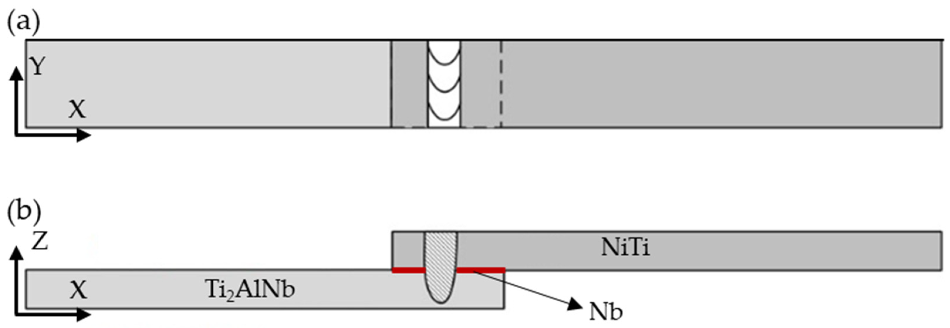
2. Materials and Methods

NiTi (51.9 at% Ni) shape memory alloy sheets with the dimension of 100 mm × 10 mm × 0.7 mm (length × width × thickness) and Ti2AlNb (87.6 at% Ti) sheets with the dimension of 100 mm × 10 mm × 0.6 mm were used in the laser welding experiments. Nb (99.9% purity) foils with 30 mm × 10 mm × 0.1 mm size were chosen as the interlayer material.
Before welding, a fine sandpaper was used to polish and remove the oxide film on the surface of each workpiece. Then, the specimens were cleaned with acetone and ethanol, and subsequently dried. A high power YAG laser W-LTA4030 (HGTECH, Wuhan, China), produced by HGTEC, with a wavelength of 1070 nm was used to create lap joints between NiTi and Ti2AlNb alloys. Several experiments were performed to optimize the welding parameters. The ranges of welding power (P) and welding speed (v) were changed from 900 to 1300 W and 1.5 to 4.0 mm/s, respectively. The total length of the weld was 8 mm. In this investigation, the NiTi sheet was placed on the top of the Ti2AlNb sheet, as detailed in Figure 1. The welding specimens were fixed using a special welding fixture, which was designed to minimize the gap between the base materials. Pure argon was used as the shielding gas at a flow rate of 20 L/min to prevent oxidation. The shielding gas was inserted both at the front and back of the weld.
The detailed experimental parameters for the laser welding experiments are depicted in Table 1.
The welded joints were cut into small metallographic specimens, mounted in epoxy resin, mechanically ground with sandpaper from 600 to 1500 grit, polished and etched for microstructure analysis. The microstructure of the samples was analysed using an Olympus BX53M optical microscope (OM, OLYMPUS, Tokyo, Japan). Furthermore, a scanning electron microscope (SEM, HITACHI, Tokyo, Japan), equipped with an Energy Dispersive X-ray (EDS) system was used to further assess the joint’s microstructure features. An Instron 5548 micro-tensile tester (INSTRON, Boston, MA, USA) was used to measure the tensile strength of dissimilar lap joints with a displacement speed of 1.5 mm/min at room temperature. Three samples were tested under each experimental parameter to determine the shear force. The microstructure of the fractured surfaces was observed on the SEM.

3. Results and Discussion

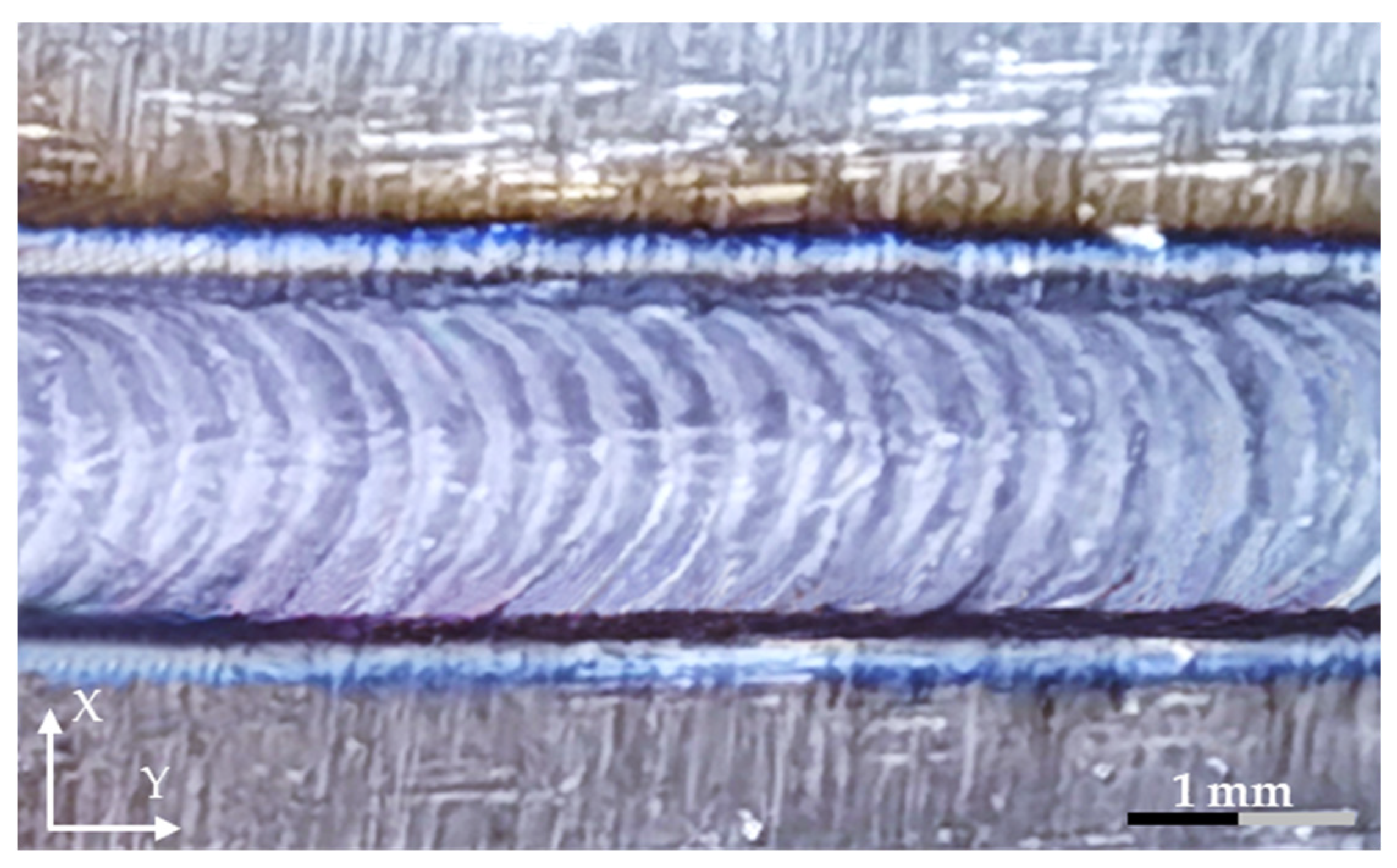
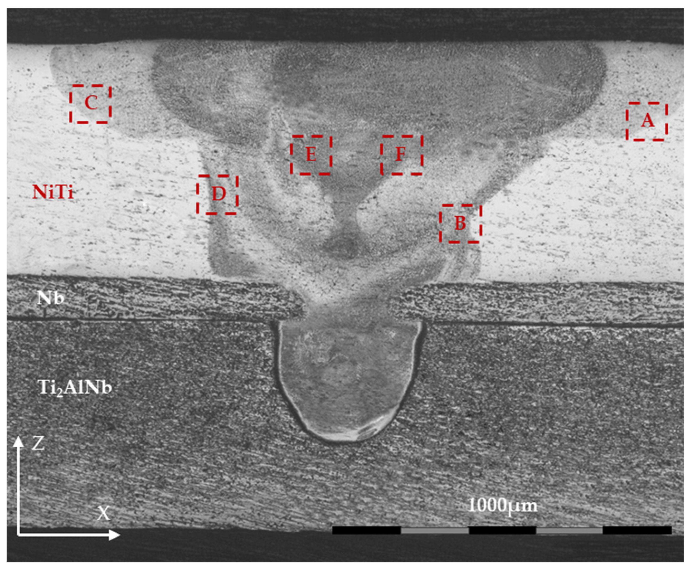
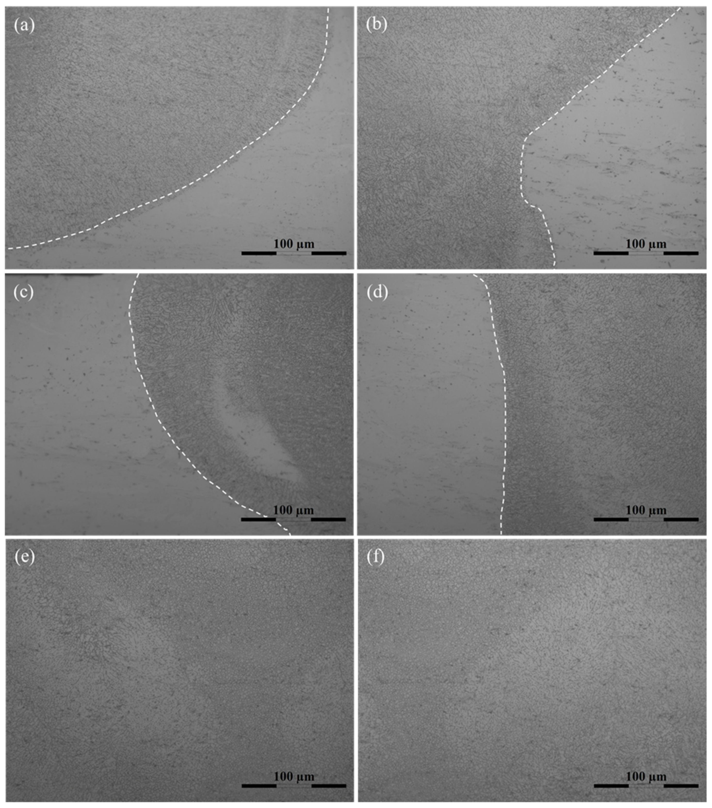
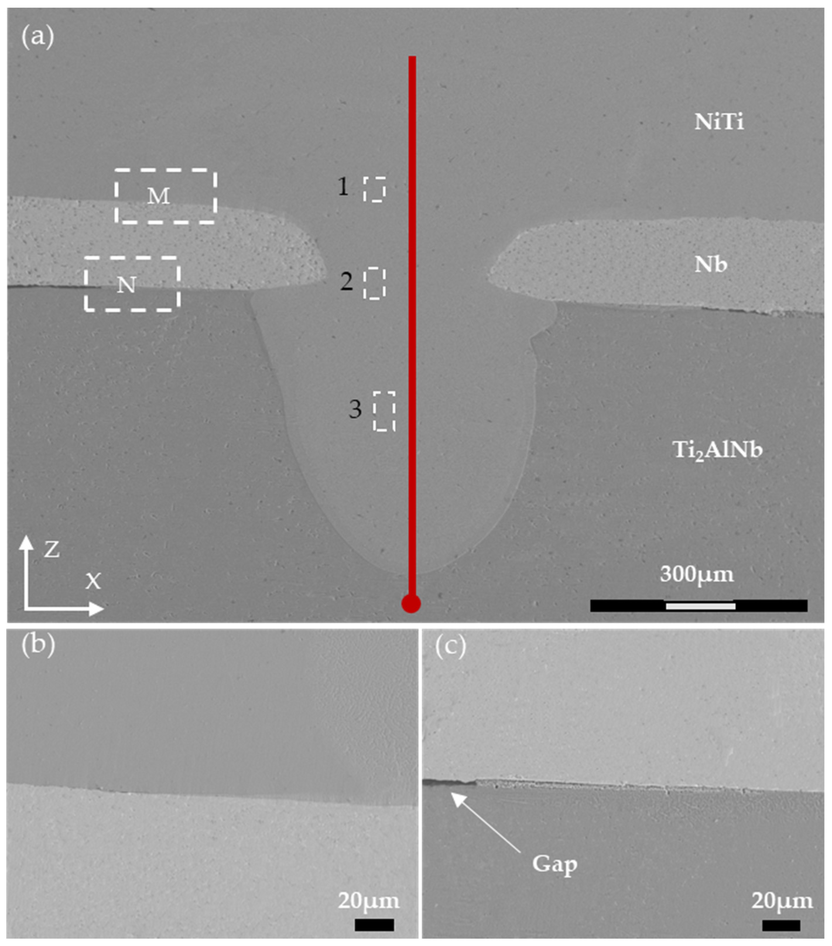
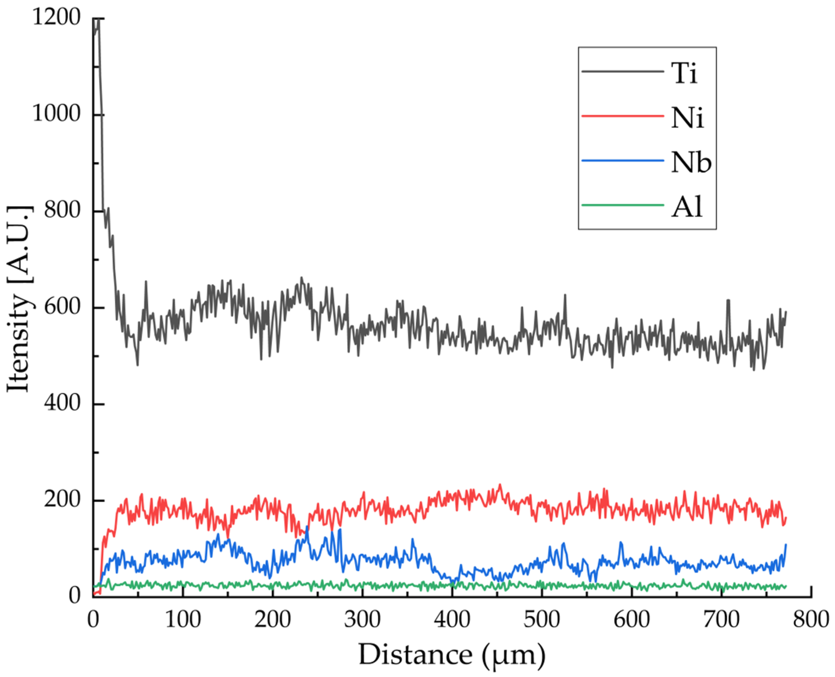
3.1. Macro Morphology and Microstructure of Welded Joint

Figure 2 depicts the bead’s appearance on the front side of the joint made with a 1100 W laser power and 3 mm/s of welding speed (No. 3 sample). It could be seen that the surface of the weld had a bright, silver metallic luster aspect, indicating that the surface of the weld was not contaminated by oxygen or nitrogen. The appearance of the intermetallic compound NiTi2 resulted in a brittle weld and caused cracks in the welded joint upon cooling due to thermal stresses that developed [25,32]. Hydrides in the weld could also cause the weld to fracture [10,33]. The weld surface of the lap joint was well-formed; no defects such as cracks and bead collapse were observed according to the macroscopic appearance of the joint.
Figure 3 details the macroscopic morphology of the cross-section of the welded joint when the laser power was 1100 W and the welding speed was 3 mm/s (No. 3 sample). It can be well observed that the fusion zone penetrates the Nb interlayer towards the Ti2AlNb sheet along the Z-axis direction. The weld penetration depth at the Ti2AlNb plate was close to 62 % of the thickness of the base metal, corresponding to roughly 370 µm. Compared to NiTi and Ti2AlNb, Nb has a relatively high thermal conductivity (18.0 W m−1 K−1 and 7.4 W m−1 K−1 for NiTi and Ti2AlNb, while for Nb the value is of 52.3 W m−1 K−1) [34,35,36] and can conduct the laser heat from the NiTi toward the Ti2AlNb sheet. Nb can undergo a eutectic reaction with NiTi according to the pseudo-binary NiTi-Nb phase diagram, preventing the formation of brittle intermetallic compounds [34].
The weld width on the Ti2AlNb sheet was smaller than that of the NiTi sheet, while it appeared to be larger than that of the Nb interlayer in the X-axis direction, which was caused by the gradual heat loss along the Z-axis. The maximum width on the top weld of the NiTi sheet was about 1830 µm and the maximum width of the Ti2AlNb sheet was 430 µm, while the width of the Nb interlayer was 300 µm. The temperature gradient experienced by each material along the thickness of the weld was responsible for such a difference in width. The temperature on the top surface of the weld was higher than that on the bottom surface, which caused more material to melt. Nb is a refractory metal with a melting point of 2477 °C, which is significantly higher than those of NiTi (1310 °C) and Ti2AlNb (1746 °C) [37,38], resulting in a narrow melting width in the weld. Although Ti2AlNb was positioned at the bottom of the joint, the heat was enough to partially melt its thickness. Melting of the Ti2AlNb sheet was also assisted by the high thermal conductivity of Nb.
To evaluate the microstructures of the joint, high magnification photos obtained at different locations within the joint (spots A, B, C, D, E and F in Figure 3) on the NiTi side are depicted in Figure 4. The dendrites nucleated from the cold base material and grew up towards the weld centreline. The low heat input of laser welding associated with the high cooling rates of the process promotes the formation of refined dendrites. Near-equiaxed grains were also observed in the central zone of the weld, as shown in Figure 4e,f, which corresponds to regions E and F of Figure 3. The high temperature in the centre of the weld and change in thermal gradient across the fusion zone was helpful in promoting the formation of such grains. Typically, the presence of equiaxed grains is preferable as it can improve joint strength and toughness.
SEM images of the interfaces between the Nb and both the NiTi and the Ti2AlNb base materials are shown in Figure 5a. The red circle was the starting point for the line scan. As shown in Figure 5b,c, the Nb interlayer formed defect-free interfaces with the NiTi sheet, while there was a small gap between Ti2AlNb and the Nb interlayer at a particular distance from the centre of the weld, which might aid in fracture propagation upon mechanical testing.
The line EDS analysis results are depicted in Figure 6. It can be observed that the intensity of Ni and Nb remains practically constant within the fusion zone. At some locations minor shifts in composition are observed, which can be attributed to the Marangoni effect resulting from the melting and mixing of the three materials. Another interesting point is the fact that Nb exists in both the NiTi and Ti2AlNb regions. The Nb interlayer can constitute a protective barrier, which is beneficial to improve the performance of the welded joint [30,31]. Nb can exist in the form of solid solution in both alloys and, depending on the atomic percentage, it can promote the formation of new phases in both base materials [39,40]. Table 2 details the results of EDS chemical analysis in regions 1, 2 and 3 of Figure 5a. The atomic ratio of Ti and Ni in the three regions is close to 1, and the chemical constitutions were very close to original NiTi base material. In fact, up to 3 at. % of Nb can be dissolved in NiTi. As observed in the electron microscopy images, no secondary phases were seen, which further suggest that Nb-enriched NiTi solid solution was formed [41]. Previous work has shown that NiTi-Nb hypoeutectic structures can be formed when the Nb content ranges between 3 and 20 at. % [42].

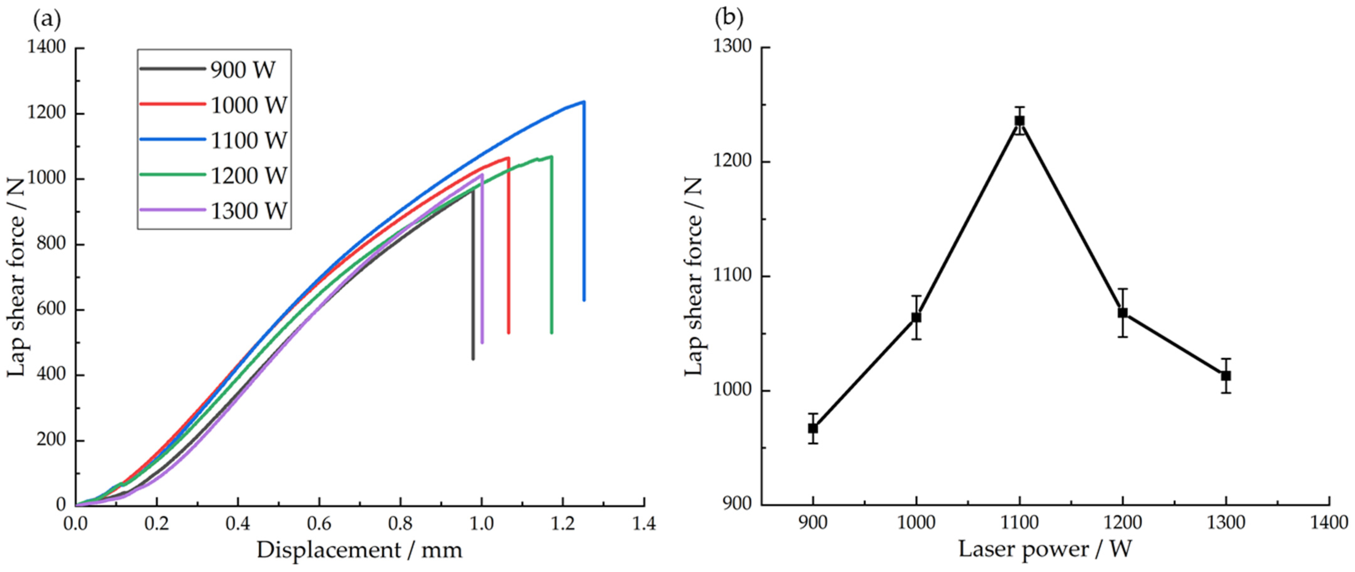
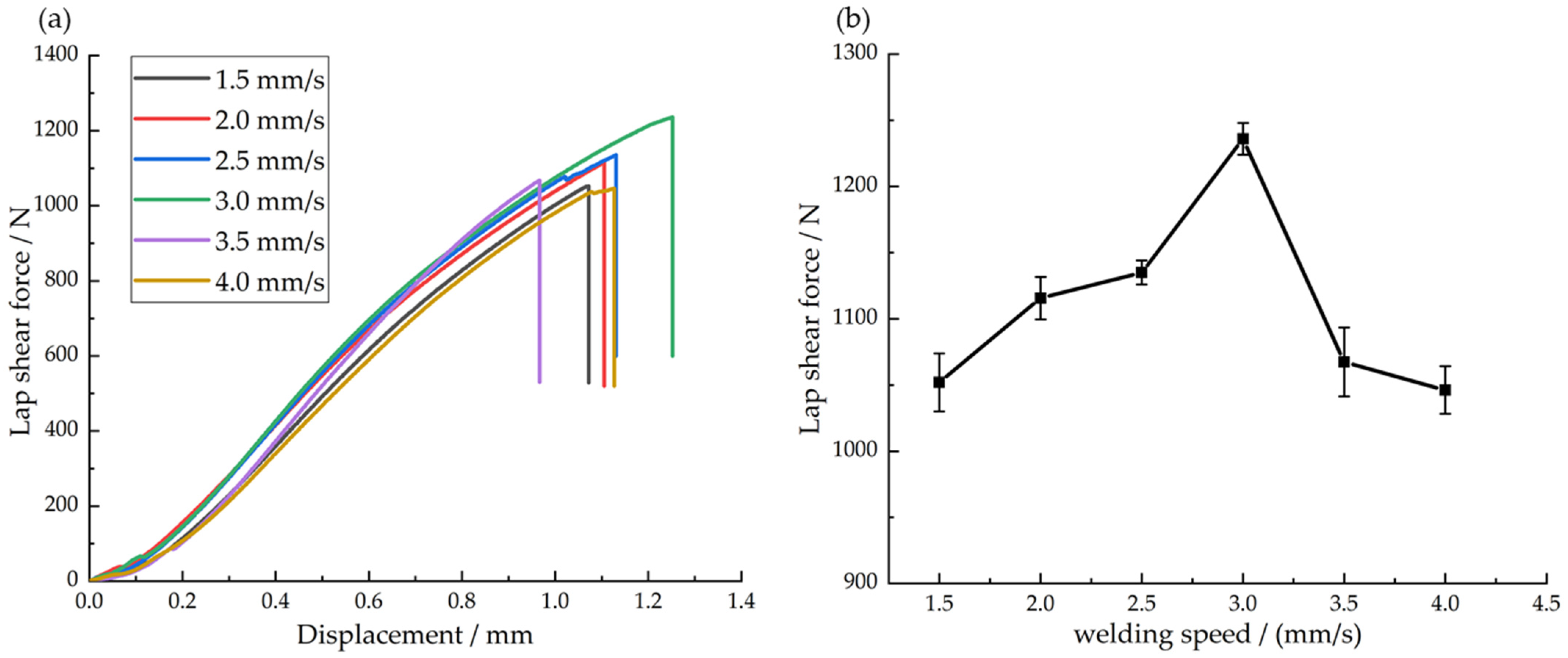
3.2. Mechanical Properties of Lap Joint Tensile

Keeping other factors constant, changes in the laser power (P) and welding speed (v) directly affect the energy input during welding. The laser power is positively correlated with heat input, but the welding speed is negatively correlated with heat input. Therefore, without considering efficiency, the relationship between the laser heat input (Q) and these welding parameters can be expressed as Q = P/v.
Figure 7 details a summary of the mechanical properties obtained after tensile lap shear testing joints obtained with different combinations of process parameters, keeping the welding speed constant at 3 mm/s. When the laser power was 900 W, the lap joint tensile strength was 967 N; when the laser power was 1100 W, the lap joint tensile strength was 1236 N, which was the highest tensile strength, and the corresponding maximum displacement was 1.26 mm; when the laser power was 1300 W, the lap joint tensile strength was 1069 N. Figure 7b shows the average tensile strength of lap joints under different laser powers. The tensile strength of the lap joints first increased and then decreased with the increase of laser power, which was caused by the continuous increment in heat input. resulting from the rise in power and constant speed. When the laser power was 900 W and 1000 W, the laser heat input was insufficient to promote a sound joint, resulting in lower strength. The heat conduction gradually reduced along the decreasing direction of the temperature gradient of the weld, resulting in a smaller cladding area on the Ti2AlNb side and less molten metal. Although the NiTi sheet was well joined to the Nb interlayer, the connection strength between the Ti2AlNb sheet and the Nb interlayer was weak. When the laser power was 1200 W and 1300 W, the larger laser heat input would cause a severe collapse of the weld surface, and even burn through the weld, thus reducing its strength.
Figure 8 shows the tensile strength of the lap joint when the laser power was kept constant at 1100 W, while the welding speed was varied. When the welding speed was 1.5 mm/s, the lap joint tensile strength was 1052 N; when the welding speed was 4 mm/s, the lap joint tensile strength was 1048 N, while the welding speed was 3 mm/s, the maximum tensile strength of 1236 N was obtained. Figure 8b details the average tensile strength of lap joints for different welding speeds. The tensile strength of the lap joints increased first and then decreased with the increase of welding speed. This is related to the variation in heat input of laser welding, which was continuously decreasing when the laser power was kept constant, while the welding speed was increased. Similarly, to what was previously explained when addressing the impact on changing the laser power, when the welding speed was too low, the heat input during welding was excessive, causing the weld to burn through the materials and reduce the tensile strength. When the welding speed was too high, insufficient heat was given to the materials making the weld depth too shallow, resulting in a decrease in the strength of the welded connection.
The tensile strength of dissimilar NiTi-Ti2AlNb lap joint was ultimately determined by the welding parameters. When the heat input energy was too low, the materials could not be effectively joined. On the other hand, the weld would collapse when the heat input energy was very high. Therefore, proper control of the heat input is fundamental to improve the joint’s mechanical properties.

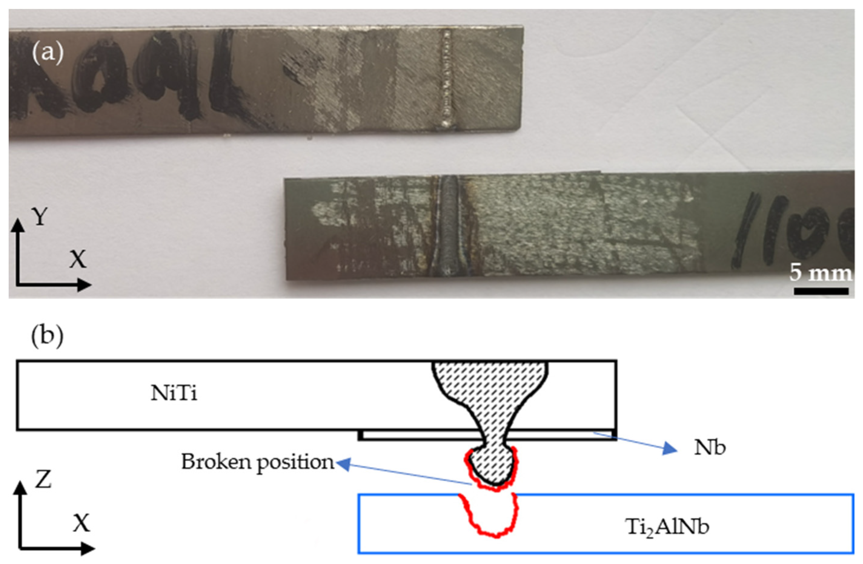
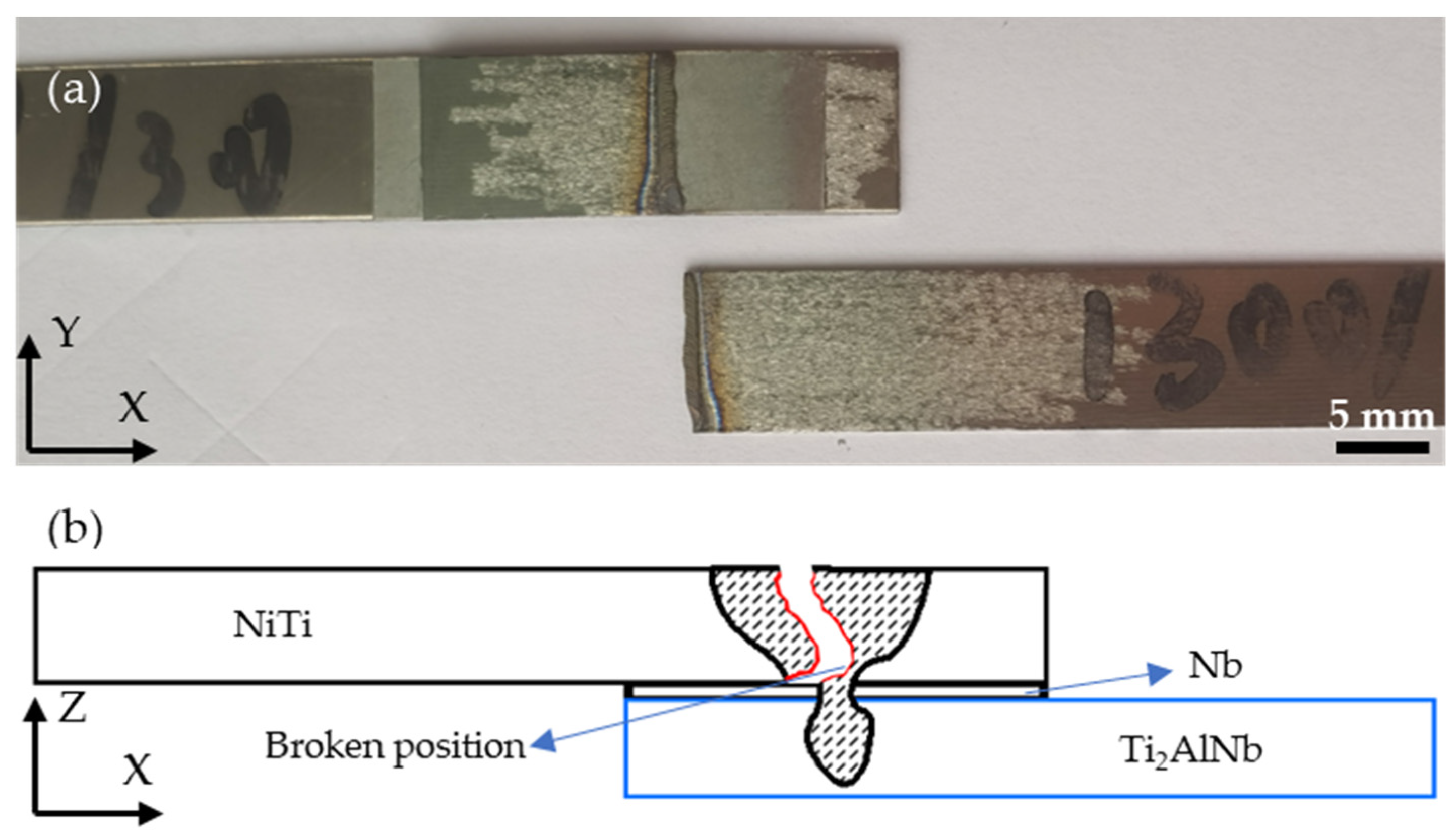
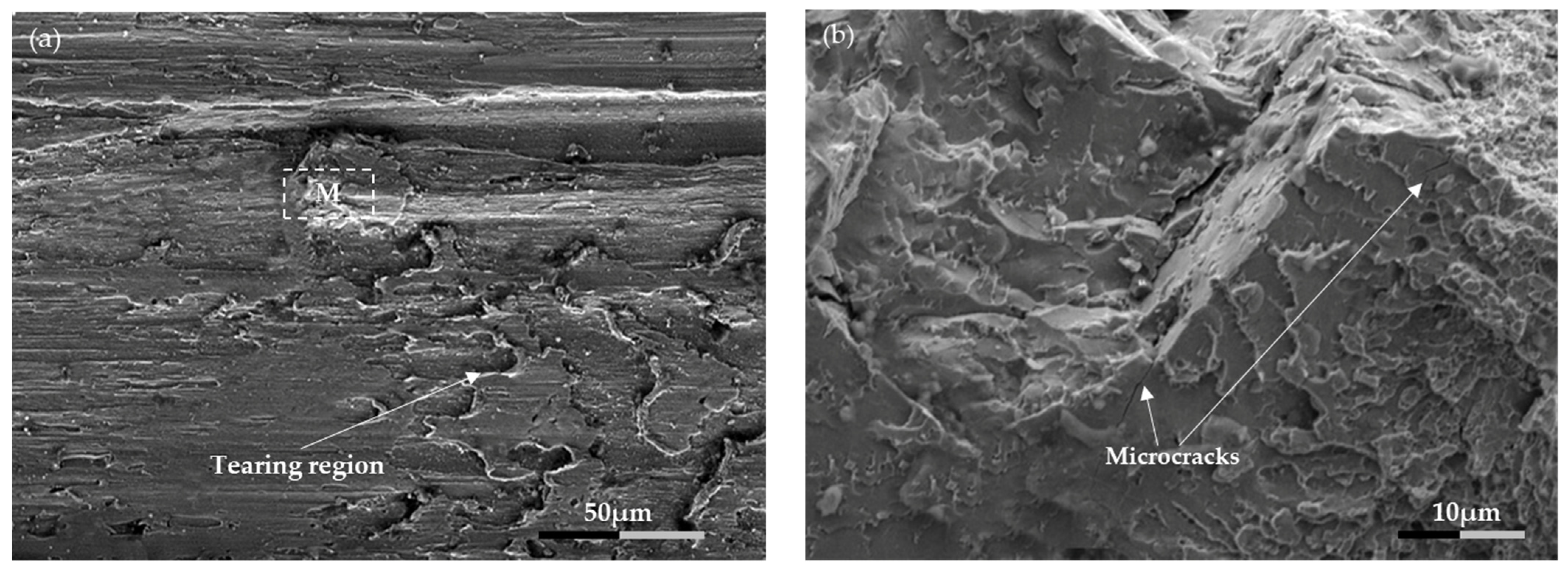
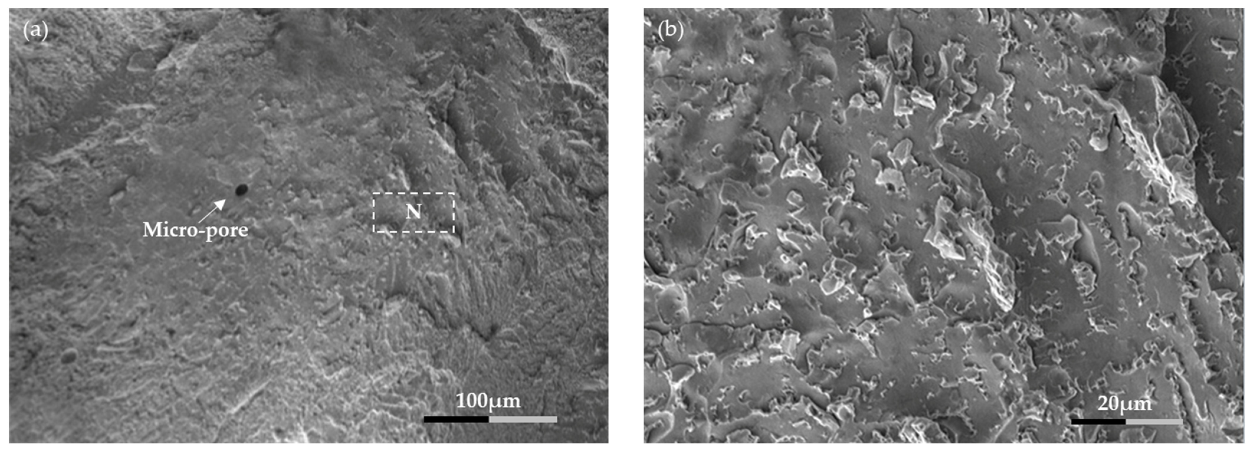
3.3. Fracture Characteristics of Lap Joint

In this work, two fracture modes were observed by changing the laser power and welding speed. The broken positions of fracture mode I and fracture mode II occurred at the interface between Nb interlayer and Ti2AlNb and the weld centre of the NiTi sheet, respectively. The tensile fracture specimens of experiments No. 3 and No. 5 were used to analyse the fracture mechanisms of the two fracture modes in this subsection.
When the laser power was 1100 W and the welding speed was 3 mm/s (condition No. 3), the NiTi sheet, Nb interlayer, and Ti2AlNb sheet were effectively joined, which resulted in maximum tensile strength. As shown in Figure 9, the broken position occurred at the bottom of the joint on the Ti2AlNb alloy side (defined as fracture mode I), while NiTi and Nb interlayer were firmly bonded together. The strength of the fusion zone dictated by the Nb interlayer and NiTi sheet mixing, which was higher than the fusion zone created by the Nb interlayer and Ti2AlNb sheet. This can be related to the hypoeutectic bonding zone formed between Nb and NiTi [42]. The above EDS analysis (refer to Table 2) results indicated that a NiTi-Nb hypoeutectic structure existed in the weld area. The starting point of the fracture might be at the previously observed small gap existing between the Ti2AlNb and Nb interlayer. When the laser power was 1300 W, and the welding speed was 3 mm/s (condition No. 5), the width and depth of the weld on the Ti2AlNb side were further increased, and the fracture position was located on the centre of the NiTi side (defined as fracture mode II), as shown in Figure 10. Although the penetration depth of the weld was effectively increased, excessive heat input resulted in a burned weld and subsequent decrease in the strength of the joint.
The micrographs of the fracture interface under the two identified fracture modes are shown in Figure 11 and Figure 12, respectively. Figure 11a illustrates an SEM image of the fractured joint on the Ti2AlNb side. It can be observed that there are tearing characteristics along the weld interface. As shown in Figure 11b, marks with cleavage characteristics and some microcracks were found. The hydrogen and oxygen absorbed by the molten pool on the Ti2AlNb side made the fracture surface brittle [33,43,44], which could have caused the weld strength to weaken. Micro pores were observed in Figure 12a, which might be due to the high laser heat input causing Ni vaporization. The rapidly vaporized metal vapor would have generated a strong stress wave, which is a hidden risk of premature failures of the welded joint [25]. A large number of fracture ridges were observed on the fracture interface (refer to Figure 12b), indicating that the fracture interface was characterized by brittle cleavage. In addition, intermetallic compounds (such as NiTi2, Ni3Ti and Ni4Ti3) precipitate under the action of high heat input [45,46,47], thus reducing tensile strength. It was interesting that both fracture mode I and mode II were brittle fractures.

4. Conclusions

NiTi and Ti2AlNb sheets were effectively joined by laser welding using a Nb interlayer. The following main conclusions could be drawn from the study:
(1) NiTi and Ti2AlNb dissimilar welded joints were achieved, forming a defect-free interface with the Nb interlayer. This proves that laser welding is an effective technology that can successfully obtain NiTi to Ti2AlNb dissimilar joints and expand their functional applications.
(2) Equiaxed grains were found in the centre of the weld, while columnar dendrites grew from the fusion line toward the centre of the weld in Figure 4. This is attributed to the gradual decrease in temperature gradient from the centre to the direction of the fusion line.
(3) The tensile strength of the lap joint was improved by optimizing the process parameters. When the laser power was 1100 W, and the welding speed was 3 mm/s, the maximum lap shear force obtained was 1236 N. It was found that the welded joint had two fracture modes. Fracture mode I showed that the tensile strength of the hypoeutectic structure formed by NiTi and Nb interlayer was stronger than the connection strength of Nb interlayer and Ti2AlNb. Both fracture mode I and mode II had brittle-like features.

Author Contributions

Conceptualization, F.G. and Z.Z.; methodology, B.P.; software, W.K. and F.G.; validation, F.G. and Z.Z.; formal analysis, F.G.; investigation, F.G., F.B.T. and Z.Z.; resources, F.G.; data curation, F.G.; writing—original draft preparation, F.G. and F.B.T.; writing—review and editing, F.G., J.P.O. and Z.Z.; visualization, Y.L.; supervision, B.P. and Z.Z.; project administration, Z.Z. All authors have read and agreed to the published version of the manuscript.

Funding

This work was supported by National Natural Science Foundation of China (No. 51775091), Science and Technology Project of Sichuan Province (No. 2020ZDZX0015). J.P. Oliveira acknowledges Fundação para a Ciência e a Tecnologia (FCT—MCTES) for its financial support via the project UID/00667/2020 (UNIDEMI).

Institutional Review Board Statement

Not applicable.

Informed Consent Statement

Not applicable.

Data Availability Statement

Not applicable.

Acknowledgments

This work was supported by National Natural Science Foundation of China (No. 51775091), Science and Technology Project of Sichuan Province (No. 2020ZDZX0015). J.P. Oliveira acknowledges Fundação para a Ciência e a Tecnologia (FCT—MCTES) for its financial support via the project UID/00667/2020 (UNIDEMI).

Conflicts of Interest

The authors declare no conflict of interest.

References

  1. Saadat, S.; Salichs, J.; Noori, M. An overview of vibration and seismic applications of NiTi shape memory alloy. Smart Mater. Struct. 2002, 11, 218–229. [Google Scholar] [CrossRef]
  2. Jani, M.J.; Leary, M.; Subic, A.; Gibson, M.A. A review of shape memory alloy research, applications and opportunities. Mater. Des. 2014, 56, 1078–1113. [Google Scholar] [CrossRef]
  3. Hartl, D.J.; Lagoudas, D.C. Aerospace applications of shape memory alloys. Proc. Inst. Mech. Eng.-Part G 2014, 221, 535–552. [Google Scholar] [CrossRef] [Green Version]
  4. Appel, F.; Wagner, R. Intermetallics: Titanium Aluminides. Encycl. Mater. Sci. Technol. 2001, 4246–4264. [Google Scholar]
  5. Dimiduk, D.M.; Miracle, D.B.; Ward, C.H. Development of intermetallic materials for aerospace systems. Mater. Sci. Technol. 1992, 8, 367–375. [Google Scholar] [CrossRef]
  6. Lutjering, G.; Williams, J.C. Titanium, 2nd ed.; Springer: Berlin/Heidelberg, Germany, 2007. [Google Scholar]
  7. Leyens, C.; Peters, M. Titanium and Titanium Alloys: Fundamentals and Applications; WILEY-VCH Verlag GmbH & Co. KGaA: Weinheim, Baden-Württemberg, Germany, 2003. [Google Scholar]
  8. Hagiwara, M.; Emura, S.; Araoka, A. Enhanced Mechanical Properties of Orthorhombic Ti2AlNb-based Intermetallic Alloy. Met. Mater. Int. 2003, 9, 265–272. [Google Scholar] [CrossRef]
  9. Oh, J.; Pyo, S.G.; Lee, S. Fabrication of multilayered titanium aluminide sheets by self-propagating high-temperature synthesis reaction using hot rolling and heat treatment. J. Mater. Sci. 2003, 38, 3647–3651. [Google Scholar] [CrossRef]
  10. Chen, X.; Xie, F.Q.; Ma, T.J. Microstructure evolution and mechanical properties of linear friction welded Ti2AlNb alloy. J. Alloys Compd. 2015, 646, 4–496. [Google Scholar] [CrossRef]
  11. Cui, Y.; Yang, D.; Liu, B. Microstructure and mechanical properties of Ti-23Al-14Nb-3Valuminide’s electron beam weld-ed joint. Trans. China Weld. Inst. 1998, 19, 130–139. [Google Scholar]
  12. Chaturvedi, M.C.; Xu, Q.; Richards, N.L. Development of crack-free welds in a TiAl-based alloy. J. Mater. Process. Technol. 2001, 118, 74–78. [Google Scholar] [CrossRef]
  13. Wu, Y.T.; Wei, W.S.; Koo, C.H. Diffusion bonding of Ti–25Al–10Nb alloy. Sci. Technol. Weld. Join. 1998, 3, 97–104. [Google Scholar] [CrossRef]
  14. Herrmann, D.; Appel, F. Diffusion bonding of γ(TiAl) alloys: Influence of composition, microstructure, and mechanical properties. Metall. Mater. Trans. A 2009, 40, 1881–1902. [Google Scholar] [CrossRef]
  15. Pan, H.; Wei, M. Key factors effecting on properties of Ti_3Al braze joints. J. Mater. Eng. 2009, (Suppl. 1), 201–205. [Google Scholar]
  16. Shi, M.; Xiong, J.; Zhang, G. Monitoring process stability in GTA additive manufacturing based on vision sensing of arc length. Measurement 2021, 185, 110001. [Google Scholar] [CrossRef]
  17. Xue, J.L.; Peng, P.; Guo, W. HAZ Characterization and Mechanical Properties of QP980-DP980 Laser Welded Joints. Chin. J. Mech. Eng. 2021, 34, 80. [Google Scholar] [CrossRef]
  18. Liu, Y.; Yao, Z.; Qin, C. Elevated temperature properties of the welding interface for Ti3Al/TC11 alloy. Rare Met. Mater. Eng. 2012, 41, 1828–1832. [Google Scholar]
  19. Zeng, Z.; Cong, B.Q.; Oliveira, J.P. Wire and arc additive manufacturing of a Ni-rich NiTi shape memory alloy: Microstructure and mechanical properties. Addit. Manuf. 2020, 32, 101051. [Google Scholar] [CrossRef]
  20. Oliveira, J.P.; Panton, B.; Zeng, Z. Laser joining of NiTi to Ti6Al4V using a Niobium interlayer. Acta Mater. 2016, 105, 9–15. [Google Scholar] [CrossRef]
  21. Zeng, Z.; Yang, M.; Oliveira, J.P. Laser welding of NiTi shape memory alloy wires and tubes for multi-functional design applications. Smart Mater. Struct. 2016, 25, 085001. [Google Scholar] [CrossRef]
  22. Sun, Z.; Ion, J. Laser welding of dissimilar metal combinations. J. Mater. Sci. 1995, 30, 4205–4214. [Google Scholar] [CrossRef]
  23. Miranda, R.M.; Assuncao, E.; Silva, R.J.C. Fiber laser welding of NiTi to Ti-6Al-4V. Int. J. Adv. Manuf. Technol. 2015, 81, 1533–1538. [Google Scholar] [CrossRef]
  24. Zoeram, A.S.; Mousavi, S. Laser welding of Ti–6Al–4V to Nitinol–ScienceDirect. Mater. Des. 2014, 61, 185–190. [Google Scholar] [CrossRef]
  25. Song, P.; Zhu, Y.; Guo, W.; Qu, P.; Kang, H.; Wen, K. Mechanism of crack formation in the laser welded joint between NiTi shape memory alloy and TC4. Rare Met. Mater. Eng. 2013, 42, 6–9. [Google Scholar]
  26. Shiue, R.H.; Wu, S.K. Infrared brazing Ti50Ni50 and Ti-6Al-4V using the BAg-8braze alloy. Mater. Trans. 2005, 46, 2057–2066. [Google Scholar] [CrossRef] [Green Version]
  27. Zhi, Z.; Panton, B.; Oliveira, J.P. Dissimilar laser welding of NiTi shape memory alloy and copper. Smart Mater. Struct. 2015, 24, 125036. [Google Scholar]
  28. Oliveira, J.P.; Fernandes, F.; Miranda, R.M. Residual stress analysis in laser welded NiTi sheets using synchrotron X-ray diffraction. Mater. Des. 2016, 100, 180–187. [Google Scholar] [CrossRef] [Green Version]
  29. Penner, P.; Liu, L.; Gerlich, A. Dissimilar resistance spot welding of aluminum to magnesium with Zn-coated steel interlayers. Weld. J. 2014, 93, 225–231. [Google Scholar]
  30. Penner, P.; Liu, L.; Gerlich, A. Feasibility study of resistance spotwelding of dissimilar Al/Mg combinations with Ni based interlayers. Sci. Technol. Weld. Join. 2013, 18, 541–550. [Google Scholar] [CrossRef]
  31. Sun, M.; Niknejad, S.T.; Zhang, G. Microstructure and mechanical properties of resistance spot welded AZ31/AA5754 using a nickel interlayer. Mater. Des. 2015, 87, 905–913. [Google Scholar] [CrossRef]
  32. Chen, Y.H.; Ge, J.W.; Liu, F.C. Micro laser welding of dissimilar materials between TiNi shape memory alloy and titanium alloy. Opt. Precis. Eng. 2014, 22, 2075–2080. [Google Scholar] [CrossRef]
  33. Yuan, B.G.; Yu, H.P.; Li, C.F. Effect of hydrogen on fracture behavior of Ti–6Al–4V alloy by in-situ tensile test. Int. J. Hydrogen Energy 2010, 35, 1829–1838. [Google Scholar] [CrossRef]
  34. Gale, W.F.; Totemeier, T.C. Smithells Metals Reference Book, 8th ed.; Elsevier Inc.: Amsterdam, The Netherlands, 2004. [Google Scholar]
  35. Shaw, J. Simulations of localized thermo-mechanical behavior in a NiTi shape memory alloy. Int. J. Plast. 2000, 16, 541–562. [Google Scholar] [CrossRef]
  36. Wu, J.; Guo, R.P.; Xu, L. Effect of Hot Isostatic Pressing Loading Route on Microstructure and Mechanical Properties of Powder Metallurgy Ti2AlNb Alloys. J. Mater. Sci. Technol. 2017, 33, 172–178. [Google Scholar] [CrossRef]
  37. Otsuka, K.; Ren, X. Physical metallurgy of TiNi-based shape memory alloys. Prog. Mater. Sci. 2005, 50, 511–678. [Google Scholar] [CrossRef]
  38. Servant, C.; Ansara, I. Thermodynamic assessment of the Al-Nb-Ti system. Ber. Bunsenges. Phys. Chem. 1998, 102, 1189–1205. [Google Scholar] [CrossRef]
  39. Zhao, X.; Lan, L.; Sun, H. Mechanical properties of additive laser-welded NiTi alloy. Mater. Lett. 2010, 64, 628–631. [Google Scholar] [CrossRef]
  40. Wu, A.; Zou, G.; Ren, J. The development status of Ti3Al alloy and its connection technology. Aeronaut. Manuf. Technol. 2007, 6, 30–35. [Google Scholar]
  41. Zhao, X.; Yan, X.; Yang, Y. Wide hysteresis NiTi(Nb) shape memory alloys with low Nb content (4.5at.%). Mater. Sci. Eng. A 2006, 438, 575–578. [Google Scholar] [CrossRef]
  42. Zhao, L.C.; Duerig, T.W.; Justi, S. The study of niobium-rich precipitates in a NiTiNb shape memory alloy. Scr. Metall. Mater. 1990, 24, 221–225. [Google Scholar] [CrossRef]
  43. Wang, R.R.; Welsch, G.E. Joining titanium materials with tungsten inert gas welding, laser welding, and infrared brazing. J. Prosthet. Dent. 1995, 74, 521–530. [Google Scholar] [CrossRef]
  44. Li, X.; Xie, J.; Zhou, Y. Effects of oxygen contamination in the argon shielding gas in laser welding of commercially pure titanium thin sheet. J. Mater. Sci. 2005, 40, 3437–3443. [Google Scholar] [CrossRef]
  45. Oliveira, J.P.; Cavaleiro, A.J.; Schell, N. Effects of laser processing on the transformation characteristics of NiTi: A contribute to additive manufacturing. Scr. Mater. 2018, 152, 122–126. [Google Scholar] [CrossRef]
  46. Yan, X.J.; Yang, D.Z.; Liu, X.P. Corrosion behavior of a laser-welded NiTi shape memory alloy. Mater. Charact. 2007, 58, 623–628. [Google Scholar] [CrossRef]
  47. Chan, C.W.; Man, H.C. Laser welding of thin foil nickel-titanium shape memory alloy. Opt. Lasers Eng. 2011, 49, 121–126. [Google Scholar] [CrossRef]
Figure 1. Schematic diagram of lap test: (a) Welded specimen in the X-Y plane; (b) Welded specimen in the X-Z plane.
Metals 11 01578 g001
Figure 2. Overall macroscopic morphology of the weld joint (No. 3 sample).
Metals 11 01578 g002
Figure 3. Macro morphology of weld cross section (No. 3 sample).
Metals 11 01578 g003
Figure 4. Microstructures of different zones on Figure 3 (No. 3 sample): (a) A zone; (b) B zone; (c) C zone; (d) D zone; (e) E zone; (f) F zone. (The white dotted line indicates the fusion zone boundary).
Metals 11 01578 g004
Figure 5. SEM images of: (a) Interface between NiTi, Nb and Ti2AlNb; (b) Zone M of Figure 5a; (c) Zone N of Figure 5a. (The red line represents the EDS line analysis.) (No. 3 sample).
Metals 11 01578 g005
Figure 6. EDS line scans across the NiTi-Nb-Ti2AlNb interface (No. 3 sample).
Metals 11 01578 g006
Figure 7. Effect of laser power on lap tensile shear force: (a) Representative lap tensile shear testing under different laser powers; (b) Mean value of lap tensile resistance under different laser powers.
Metals 11 01578 g007
Figure 8. Effect of welding speed on lap tensile shear force: (a) Representative lap tensile shear testing under different welding speeds; (b) Mean value of lap tensile resistance under different welding speeds.
Metals 11 01578 g008
Figure 9. Fracture mode I: (a) Tensile fracture specimen; (b) Schematic diagram of fracture (The red line indicates the fracture surface).
Metals 11 01578 g009
Figure 10. Fracture mode II: (a) Tensile fracture specimen; (b) Schematic diagram of fracture (The red line indicates the fracture surface).
Metals 11 01578 g010
Figure 11. SEM image of fracture interface in fracture mode I: (a) Fracture surface on Ti2AlNb side; (b) High magnification image of M.
Metals 11 01578 g011
Figure 12. SEM image of fracture interface in fracture mode II: (a) Fracture surface on NiTi side; (b) High magnification image of N.
Metals 11 01578 g012
Table 1. Laser welding parameters.
Experiment No.Laser Power (W)Welding Speed (mm/s)
19003.0
210003.0
311003.0
412003.0
513003.0
611001.5
711002.0
811002.5
911003.5
1011004.0
Table 2. Chemical analysis of different regions in Figure 5a (at. %, No. 3 sample).
RegionTiNiNb
151.8045.902.30
251.1547.221.63
353.1542.264.59
Publisher’s Note: MDPI stays neutral with regard to jurisdictional claims in published maps and institutional affiliations.

