1. Introduction
Lightweight design in the transportation sector is indispensable nowadays to cut down energy consumption and greenhouse gas emissions, accordingly. Different lightweight design strategies impose different requirements on forming technologies and production engineering in general. Thus the development and adaption of forming processes to the needs of lightweight design and ecological production is an ongoing field of research.
In hybrid lightweight design approaches, materials are applied according to their specific properties and local requirements of a component. The use of multiple materials calls for methodologies to join them. To combine the advantages of hybrid lightweight design with the high precision and high output rate of cold forging, various studies focused on joining materials by means of cold forging processes.
First investigations of composite cold extrusion were conducted by Gumm in 1964 [
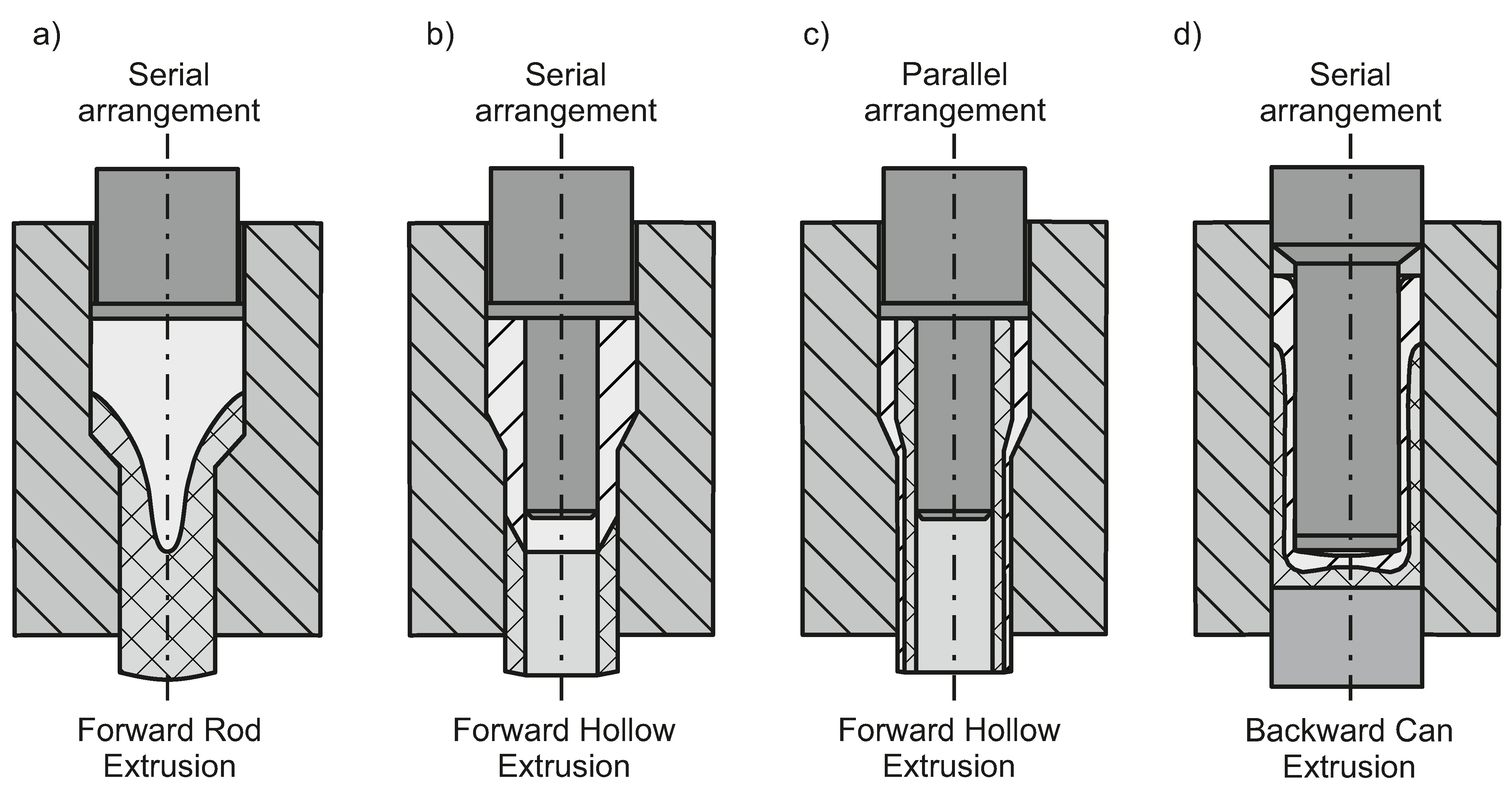
1]. The author successfully joined aluminum and copper by forward rod extrusion, forward hollow extrusion and backward can extrusion by either a serial or parallel arrangement of the forming partners, as depicted in
Figure 1a–c and showed that bonding strength of the two materials is proportional to the surface expansion of the contacting surfaces. Further studies have shown that joining a vast variety of materials by cold forging is feasible. Material combinations of steel/copper [
2], steel/nickel [
2], steel/aluminum [
3] and titan/aluminum [
4] were successfully joined by cold forging processes. The bond between joining partners can either be of metallurgical, force-fitting or form-fitting nature. In order to achieve a metallurgical bond at room temperature, the plain materials, that are covered by oxide layers, need to get in direct contact [
5]. To achieve such contact in a forming process, high surface expansions as well as high normal pressures are required [
6]. The surface expansion leads to cracks in covering oxide layers, through which the material is extruded by the high contact pressure. The contact of micro-extruded material of both joining partners finally results in a cold pressure weld. Further research by Bay has shown that preliminary treatment of joining surfaces for example, by a rotating brush can improve the weld quality [
7]. Also the heat treatment condition of the forming partners affects the bond strength [
8].
Ossenkemper et al. [
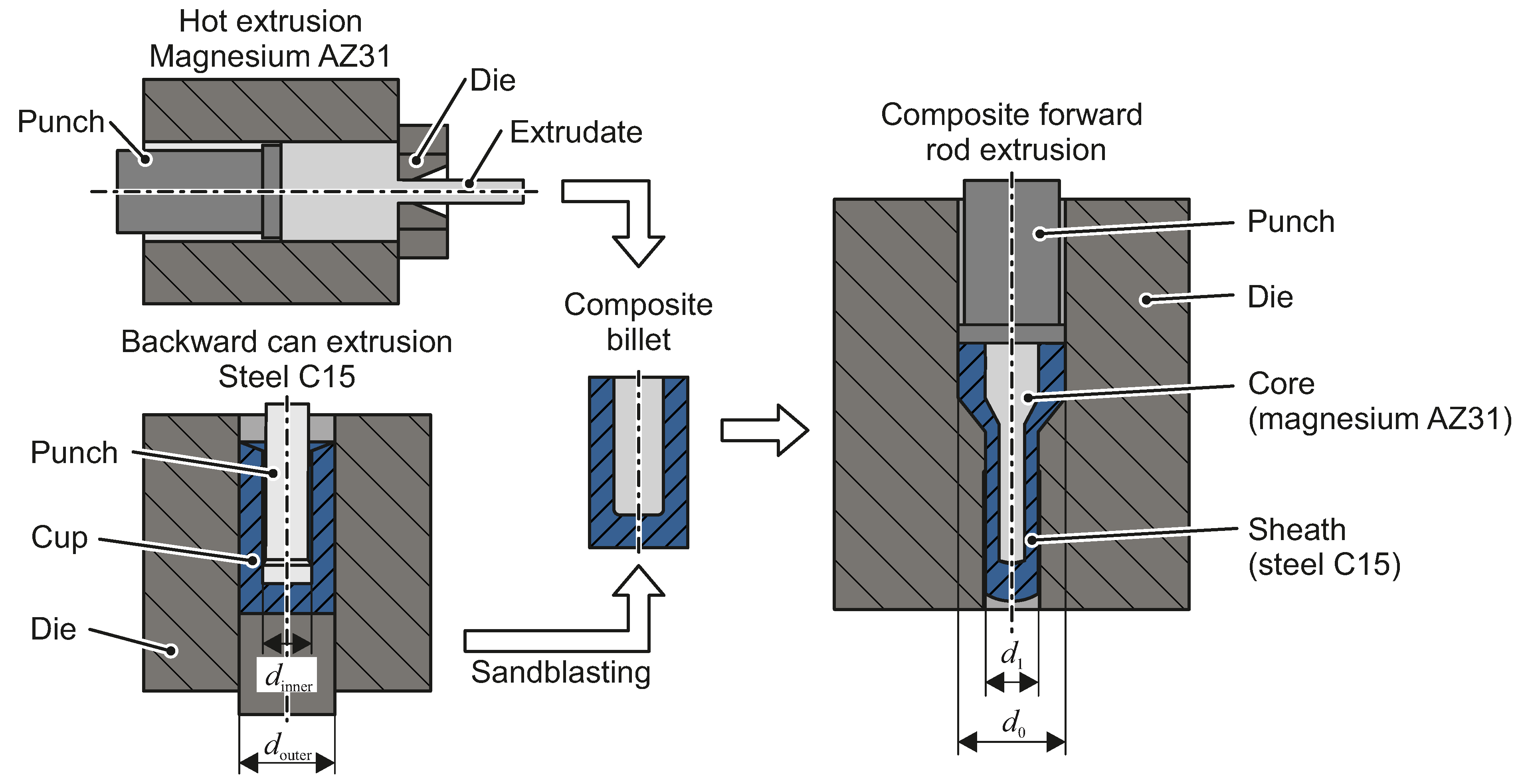
9] presented a composite cold forging process that uses hybrid semi-finished products consisting of a steel cup and a lightweight aluminum alloy cylindrical core. This composite billet is then formed by means of forward rod extrusion, using conventional tools (
Figure 2). Ossenkemper et al. [
10] showed by means of FEM -simulations that conditions for cold pressure welding are not met in composite forward rod extrusion. Instead a force-fitting bond can be achieved by the residual stress acting on the contact area of core and sheath after forward rod extrusion. The resulting bond strength can be described by an analytical model that takes yield stresses and Young’s moduli of the forming partners into account. The model is in agreement with push-out tests of shafts produced by cold forged billets made from backward can extruded steel cups. However, this is only the case for a smooth, as forged, inner surface of the cold forged steel cups. Sandblasting the inner cup surface before inserting the aluminum core results in increased bond strength that even succeeds the shear yield limit of the aluminum core. As a metallurgical bond was rejected as the bond strength governing mechanism by previous studies, a micro form fit induced by aluminum flowing into the indents of the sand-blasted steel cup was identified as the pertinent mechanism [
11]. Apart from that, the authors also implemented a macroscopic form-fit in tangential direction by using non-round core geometries and corresponding punch geometries in backward can extrusion for production of the steel cups. A form-fit in axial direction can be achieved by applying shaft shoulders on both ends of the shaft.
The presented method is especially suited for the production of gear shafts, as the parallel arrangement of steel and aluminum allows for weight reduction with only small losses in torsional and bending stiffness, which are needed to withstand torque and axial forces during service life of a gear shaft.
The goal of this paper is to further increase the lightweight potential of the composite cold forging process. The use of magnesium as a core material as well as granular media cores that are removed after forming are investigated.
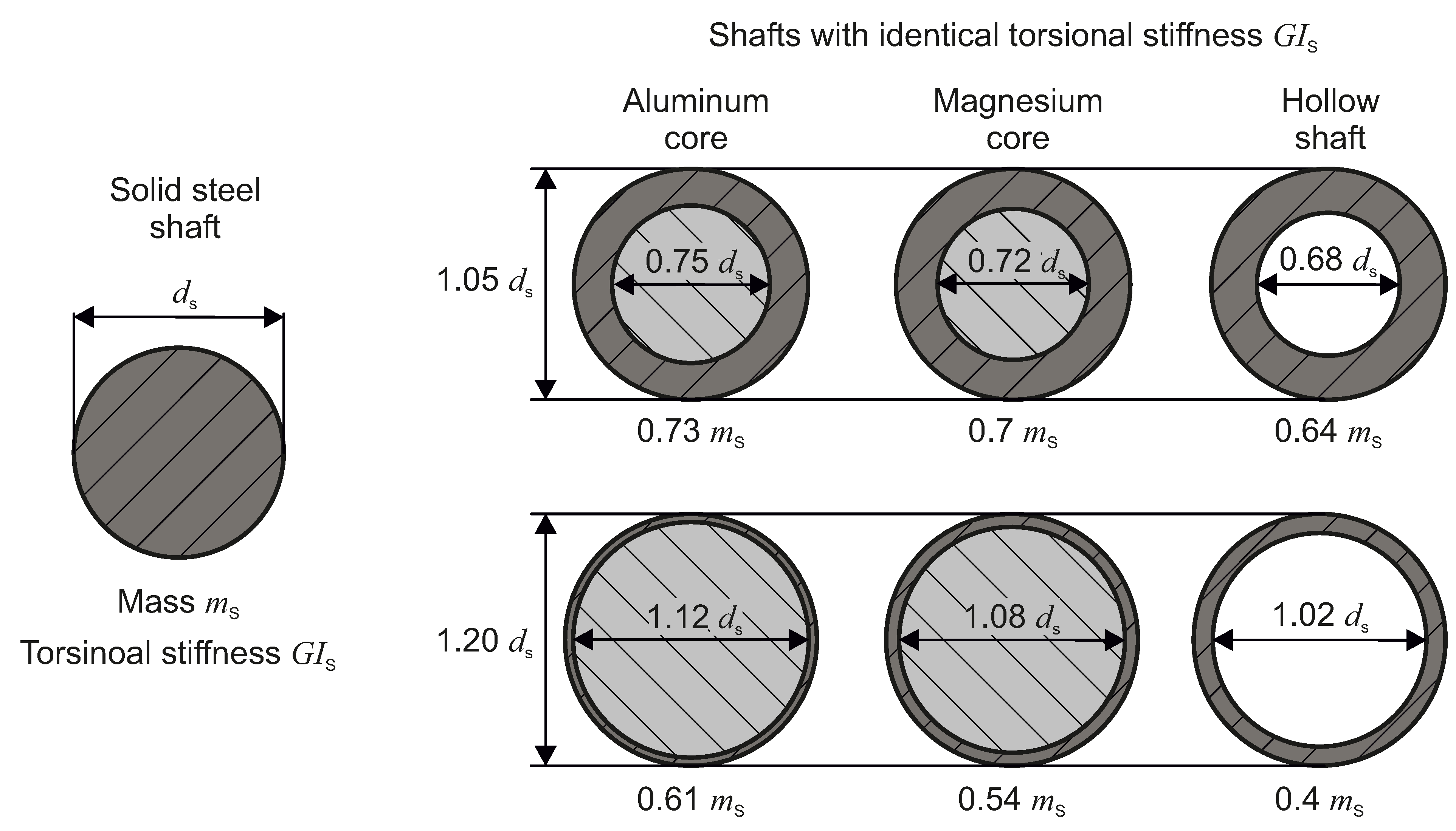
Figure 3 compares the lightweight potential of magnesium-steel composite shafts and hollow shaft to aluminium-steel composite shafts.
A solid steel shaft with given diameter and torsional stiffness is considered. This shaft is substituted by a composite or hollow shaft with identical torsional stiffness. To achieve the same stiffness, the outer diameter of the composite or hollow shaft needs to be increased due to the weaker shear moduli of the core materials. For an increasing cross sectional area share of the core material, weight reduction increases at the expense of further increase of the outer diameter of the composite shaft. Hollow shafts and composite shafts with magnesium core are superior to aluminum-steel composite shafts in terms of weight reduction. Thus the limiting conditions of manufacturing such shafts by means of composite cold forging are studied numerically and experimentally in this paper.
Author Contributions
Conceptualization, O.H. and A.E.T.; methodology, R.G. and F.K.; software, R.G. and F.K.; validation, R.G. and F.K.; formal analysis, R.G. and F.K.; investigation, R.G. and F.K.; resources, A.E.T.; writing–original draft preparation, R.G. and F.K.; writing–review and editing, O.H. and A.E.T.; visualization, R.G. and F.K.; supervision, O.H. and A.E.T.; project administration, R.G. and O.H.; funding acquisition, A.E.T. All authors have read and agreed to the published version of the manuscript.
Funding
This work is based on investigations of the research project “Composite Cold Forging of Cold Forged Semi-Finished Parts,” funded by the German Research Foundation (DFG, Project number 270149504). Its financial support is greatly acknowledged.
Conflicts of Interest
The authors declare no conflict of interest.
References
- Gumm, P. Kombination von Umformung und Kaltpresschweissen beim Fliespressen und Rohrziehen. Ph.D. Thesis, Universität Braunschweig, Braunschweig, Germany, 1964. [Google Scholar]
- Gumm, P.; Ruge, J. Kaltpreßschweißen von Stahl/Kupfer- und Nickel/Stahl- Verbundkörpern durch Fließpressen. Werkstatttechnik 1968, 58, 468–471. [Google Scholar]
- Ruge, J.; Gumm, P. Kaltpreßschweißen von Verbundkörpern in Umformvorgängen. Schweißen und Schneiden 1969, 21, 203–209. [Google Scholar]
- Wagener, H.W.; Haats, J. Pressure Welding of Corrosion Resistant Metals by Cold Extrusion. J. Mater. Process. Technol. 1994, 45, 275–280. [Google Scholar] [CrossRef]
- Conrad, H.; Rice, L. The cohesion of previously fractured Fcc metals in ultrahigh vacuum. Metall. Trans. 1970, 1, 3019–3029. [Google Scholar]
- Bay, N. Cold Pressure Welding—The Mechanisms Governing Bonding. J. Eng. Ind. 1979, 101, 121–127. [Google Scholar] [CrossRef]
- Bay, N. Mechanisms Producing Metallic Bonds in Cold Welding. Weld. J. 1983, 62, 137–142. [Google Scholar]
- Groche, P.; Wohletz, S.; Erbe, A.; Altin, A. Effect of the primary heat treatment on the bond formation in cold welding of aluminum and steel by cold forging. J. Mater. Process. Technol. 2014, 214, 2040–2048. [Google Scholar] [CrossRef]
- Ossenkemper, S.; Haase, M.; Tekkaya, A.E. Composite Cold Forging of Shafts. In Proceedings of the 48th ICFG Plenary Meeting, Daejeon, Korea, 13–16 September 2015. [Google Scholar]
- Ossenkemper, S.; Dahnke, C.; Khalifa, N.; Tekkaya, A.E. Composite Cold Forging–Producing Steel-Aluminum-Composite Shafts with Conventional Cold Forging Tools. In Proceedings of the 50th ICFG Plenary Meeting, Shanghai, China, 3–6 September 2017. [Google Scholar]
- Ossenkemper, S.; Dahnke, C.; Tekkaya, A.E. Analytical and experimental bond strength investigation of cold forged composite shafts. J. Mater. Process. Technol. 2019, 264, 190–199. [Google Scholar] [CrossRef]
- Pollok, T.M. Weight Loss with Magnesium Alloys. Science 2010, 328, 986–987. [Google Scholar] [CrossRef] [PubMed]
- Kim, S.J.; Lee, C.; Koo, J.; Lee, J.; Lee, Y.S.; Kim, D. Improving the room-temperature formability of a magnesium alloy sheet by texture control. Mater. Sci. Eng. A 2018, 724, 156–163. [Google Scholar] [CrossRef]
- Hering, O.; Kolpak, F.; Tekkaya, A.E. Flow curves up to high strains considering load reversal and damage. Int. J. Mater. Form. 2019. [Google Scholar] [CrossRef] [Green Version]
- Soyarslan, C.; Tekkaya, A.; Akyuz, U. Application of Continuum Damage Mechanics in discontinuous crack formation: Forward extrusion chevron. J. Appl. Math. Mech. Z. Angew. Math. Mech. 2008, 88, 436–453. [Google Scholar] [CrossRef]
- Tekkaya, A.E. Ermittlung von Eigenspannungen in der Kaltmassivumformung. Ph.D. Thesis, Universität Stuttgart, Stuttgart, Germany, 1986. [Google Scholar]
- Wang, Q.; Khan, M.K.; Bathias, C. Current understanding of ultra-high cycle fatigue. Theor. Appl. Mech. Lett. 2012, 2, 031002. [Google Scholar] [CrossRef] [Green Version]
- Kolpak, F.; Hering, O.; Dahnke, C.; Tekkaya, A.E. Producing Hollow Shafts by Composite Extrusion Utilizing Granular Cores. In Proceedings of the 52nd ICFG Plenary Meeting, Donostia-San Sebastián, Spain, 5–18 September 2019. [Google Scholar]
- Chen, H.; Hess, S.; Haeberle, J.; Pitikaris, S.; Born, P.; Güner, A.; Sperl, M.; Tekkaya, A.E. Enhanced granular medium-based tube and hollow profile press hardening. CIRP Ann. 2016, 65, 273–276. [Google Scholar] [CrossRef] [Green Version]
- Chen, H.; Güner, A.; Khalifa, N.B.; Tekkaya, A. Granular media-based tube press hardening. J. Mater. Process. Technol. 2016, 228, 145–159. [Google Scholar] [CrossRef]
- Brandt, J.; Nilsson, L. A constitutive model for compaction of granular medium, with account for deformation induced anisotropy. Mech. Cohesive Frict. Mater. 1999, 4, 391–418. [Google Scholar] [CrossRef]
Figure 1.
Cold forging processes and arrangement of materials in used composite billets. (
a–
c) representing works by Gumm [
1] and (
d) investigations by Wagener and Haats [
4].
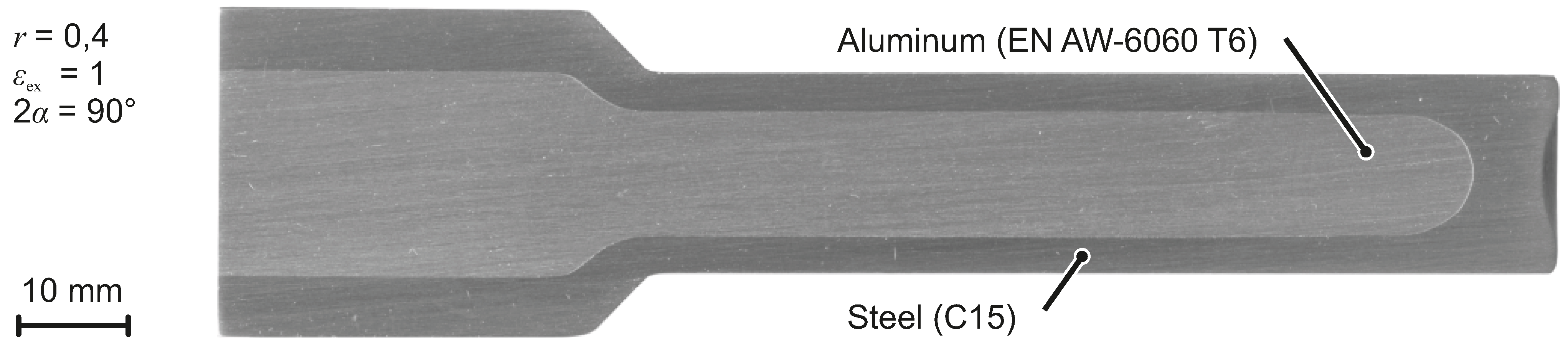
Figure 2.
Composite shaft, produced by forward rod extrusion of a backward can extruded steel shaft with an aluminum core, according to [
9].
Figure 3.
Mass savings for substituting a solid steel shaft by composite shafts with aluminum core, magnesium core and hollow shafts with identical torsional stiffness.
Figure 4.
Process route for production of composite shafts with magnesium core. The composite core, consisting of a backward can extruded steel cup and a hot extruded magnesium core is formed to a shaft by composite forward rod extrusion.
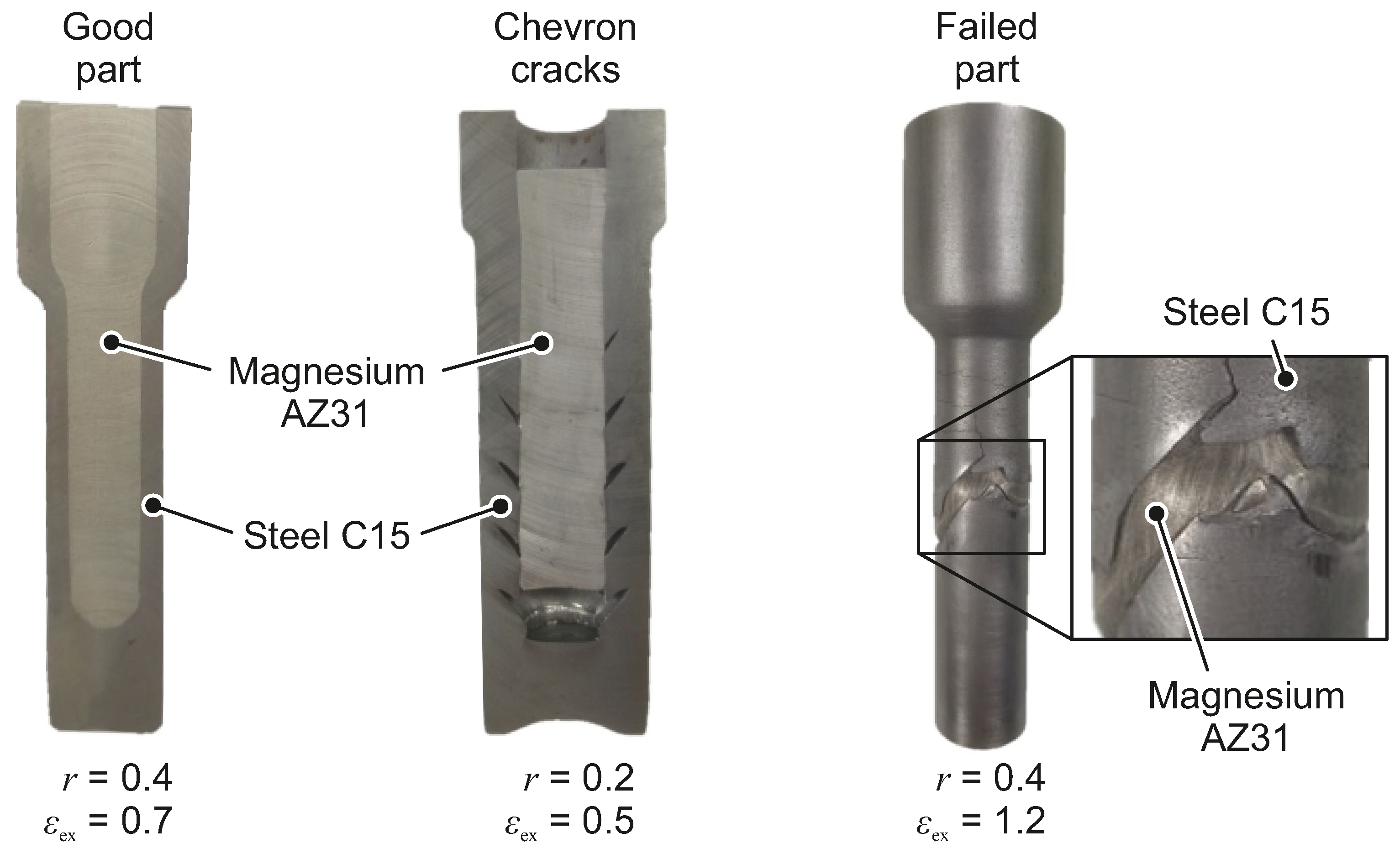
Figure 5.
Parts produced by magnesium-steel composite forward rod extrusion.
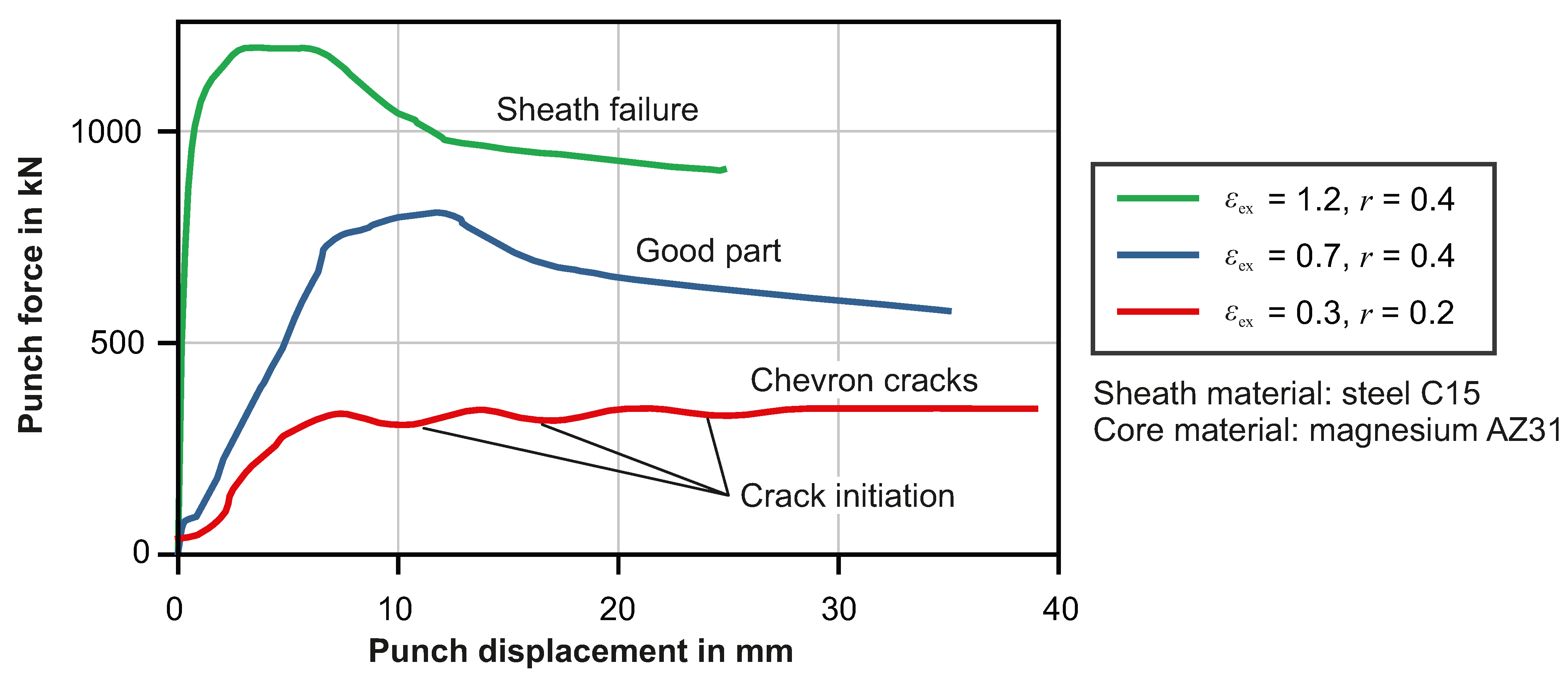
Figure 6.
Punch forces in magnesium-steel composite forward rod extrusion.
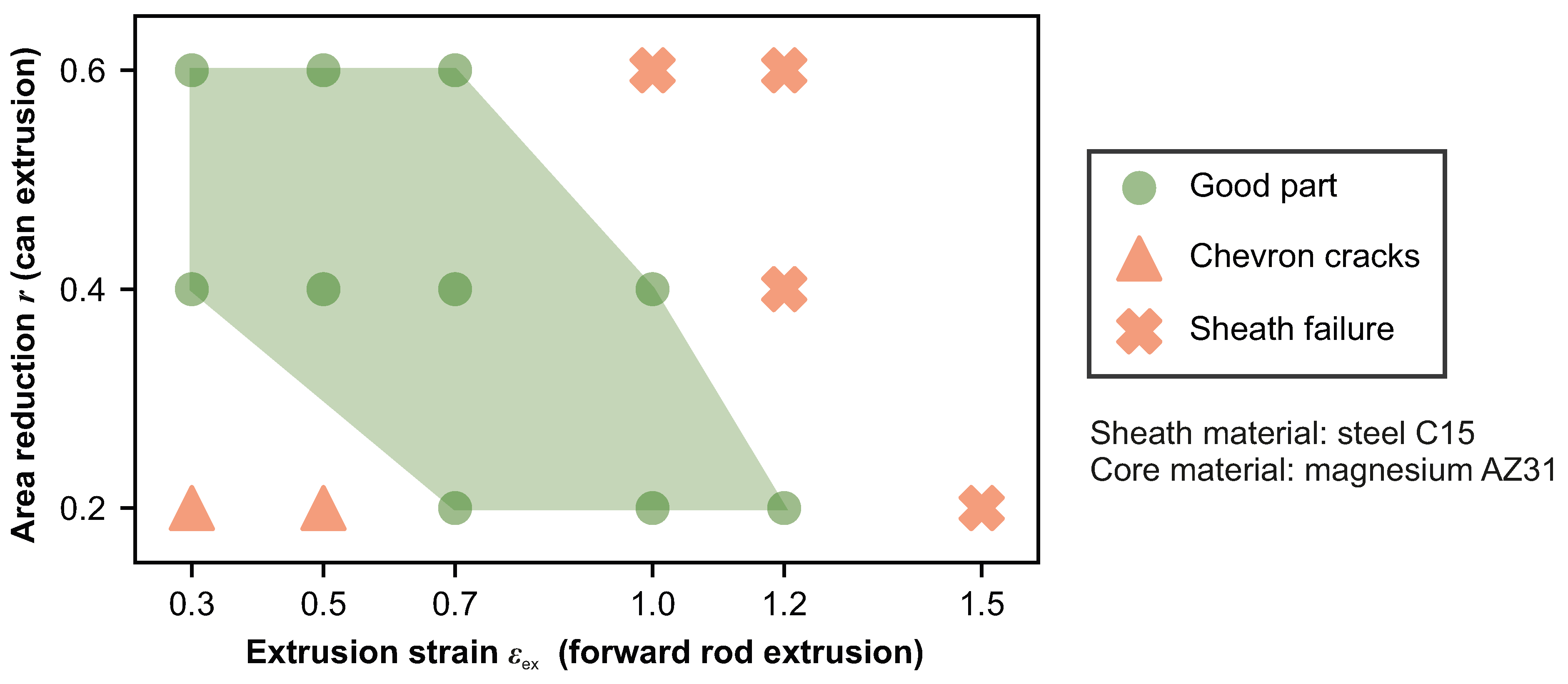
Figure 7.
Process window of magnesium-steel composite forward rod extrusion.
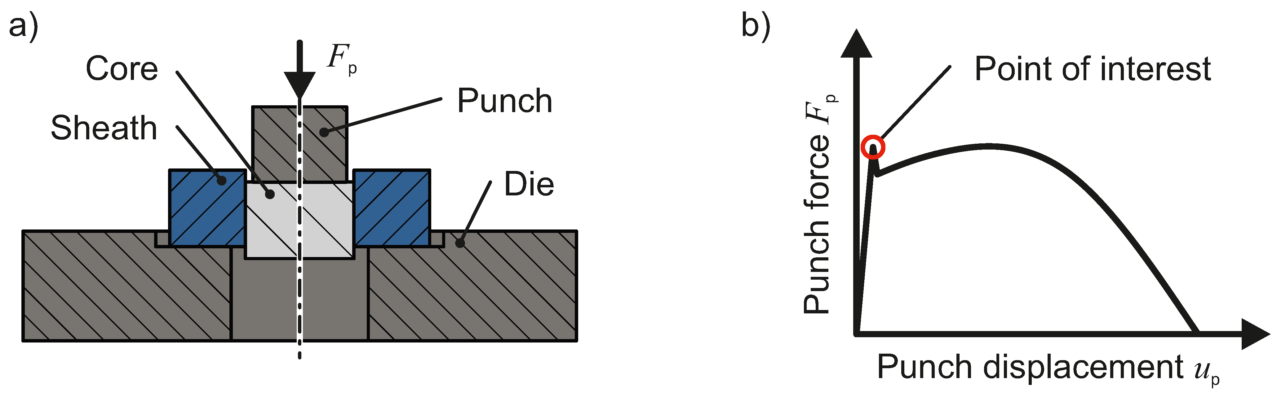
Figure 8.
Principle of push-out testing: (a) tool set up and (b) evaluation of obtained force-displacement-curve.
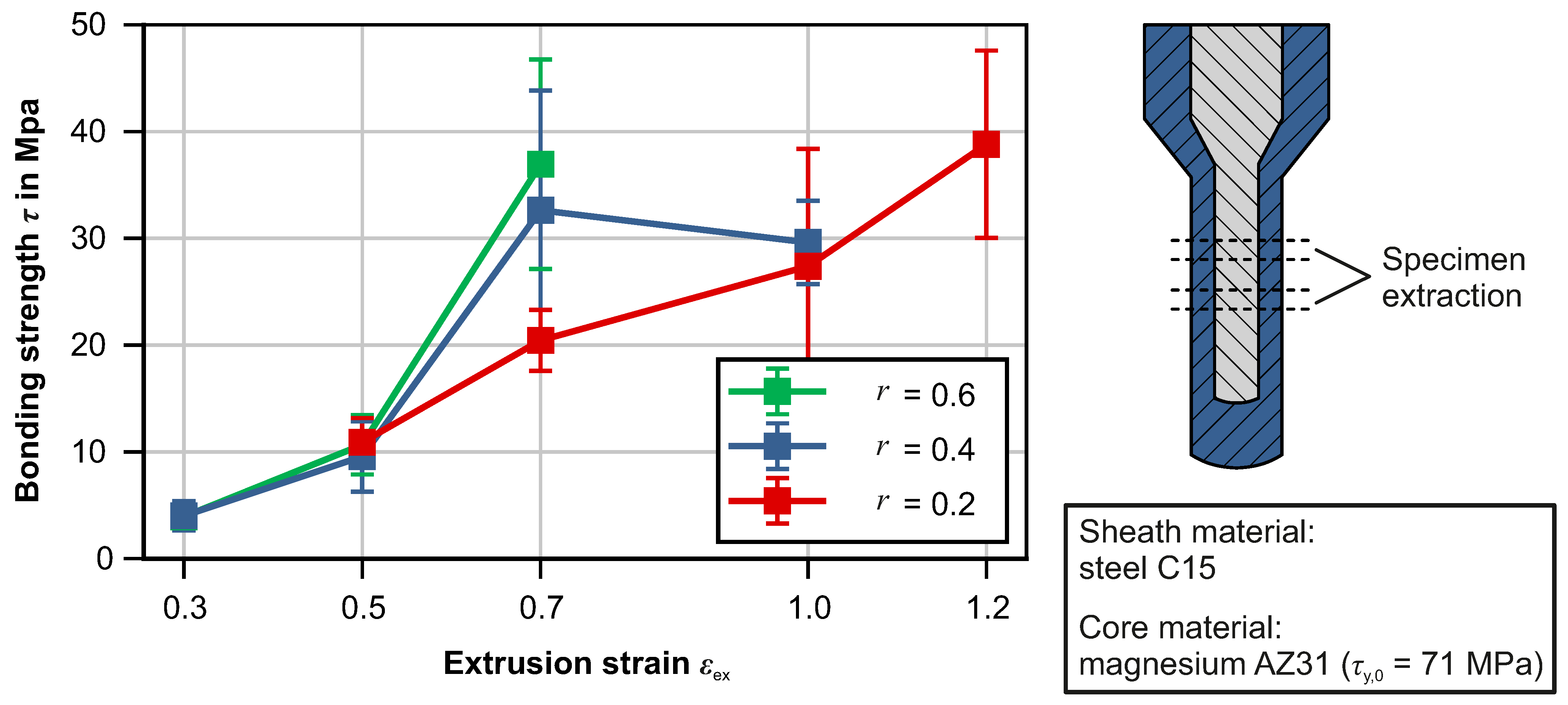
Figure 9.
Bond strength of magnesium core and steel sheath, obtained by push-out testing and location of specimen extraction.
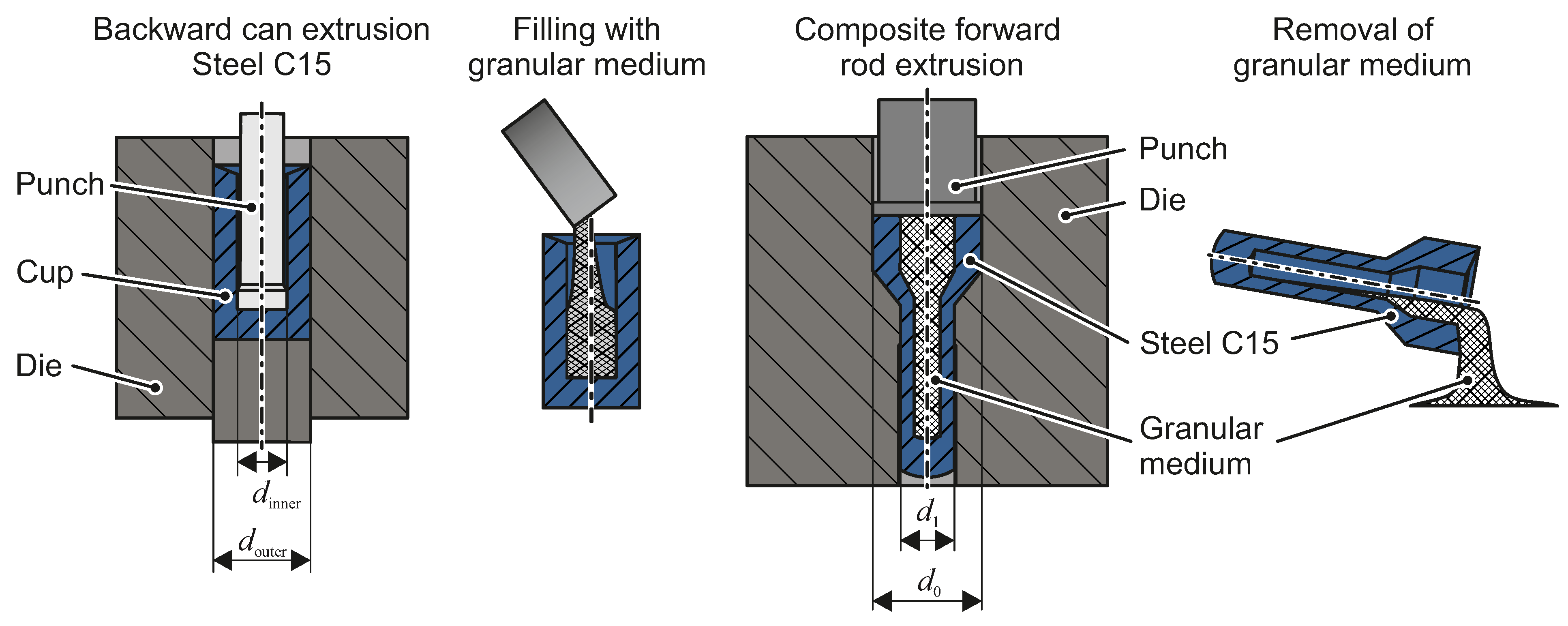
Figure 10.
Process route for production of hollow shafts by means of cold forging with granular media.
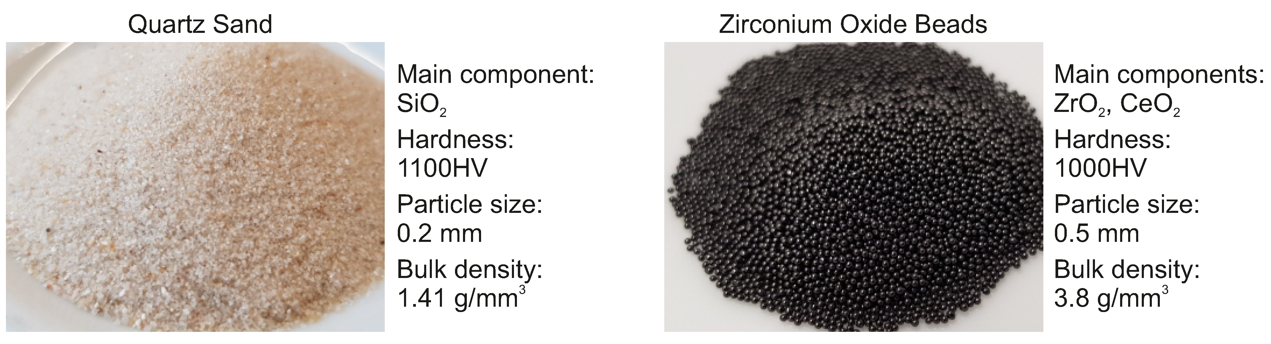
Figure 11.
Granular media used as lost cores in cold forging.
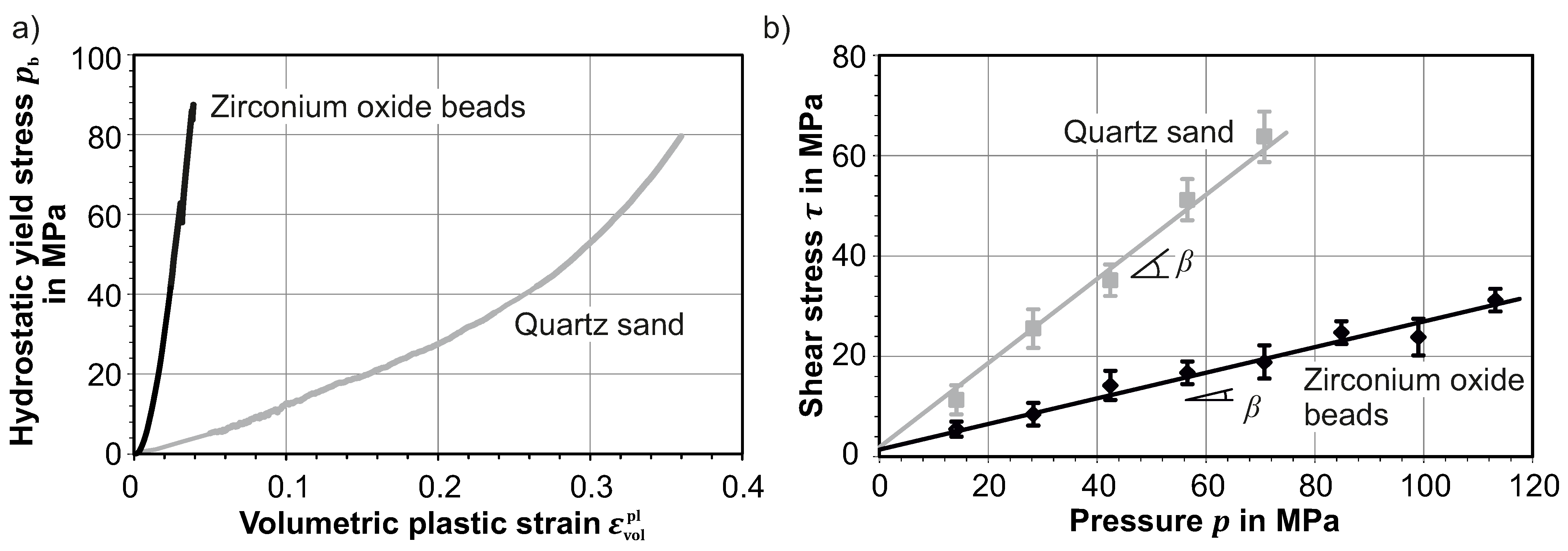
Figure 12.
Yield stresses of quartz sand and zirconium oxide beads for (
a) volumetric compression and (
b) under shear loading, according to [
20].
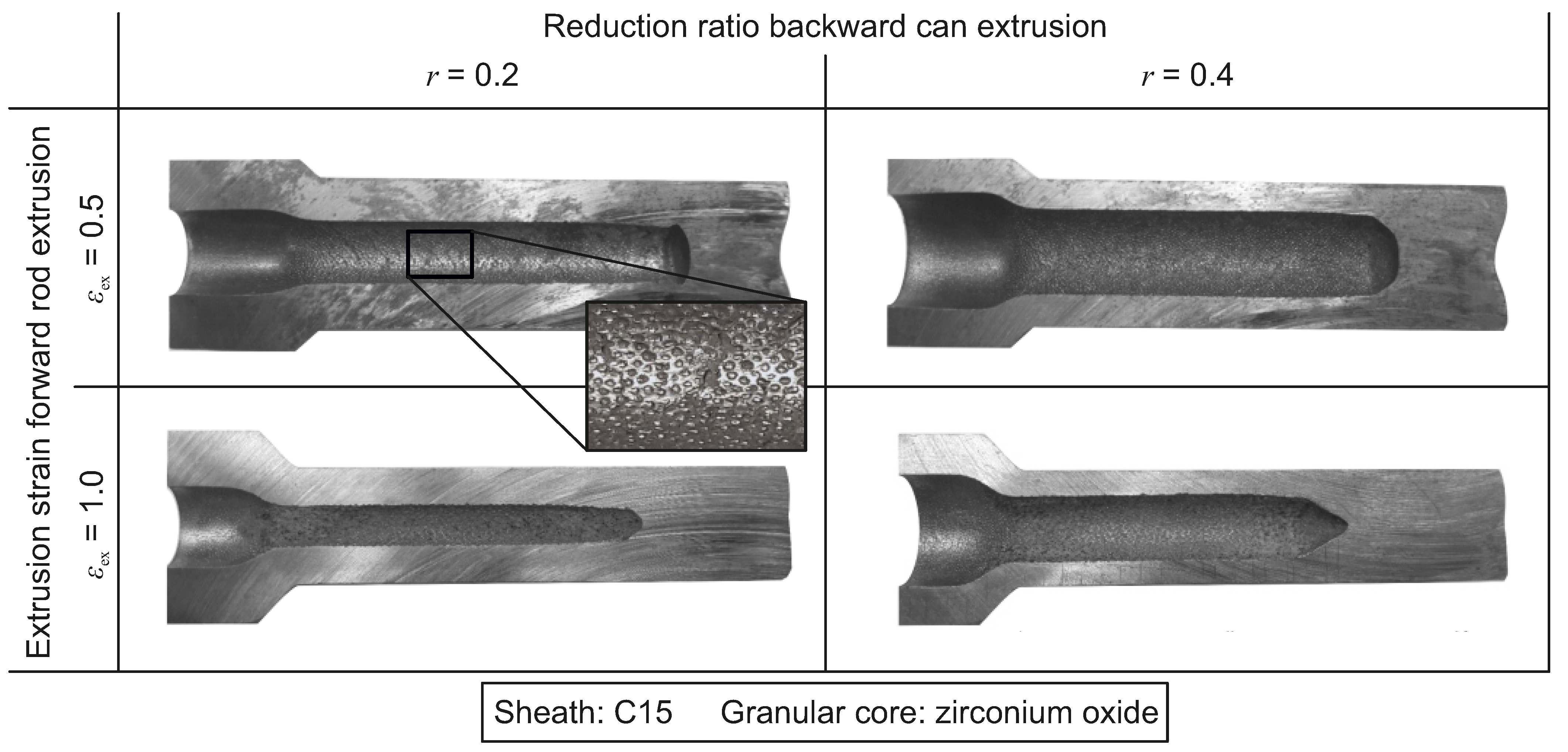
Figure 13.
Hollow shafts produced by forward rod extrusion of steel cup billets filled with zirconium oxide, cut open to reveal inner surface.
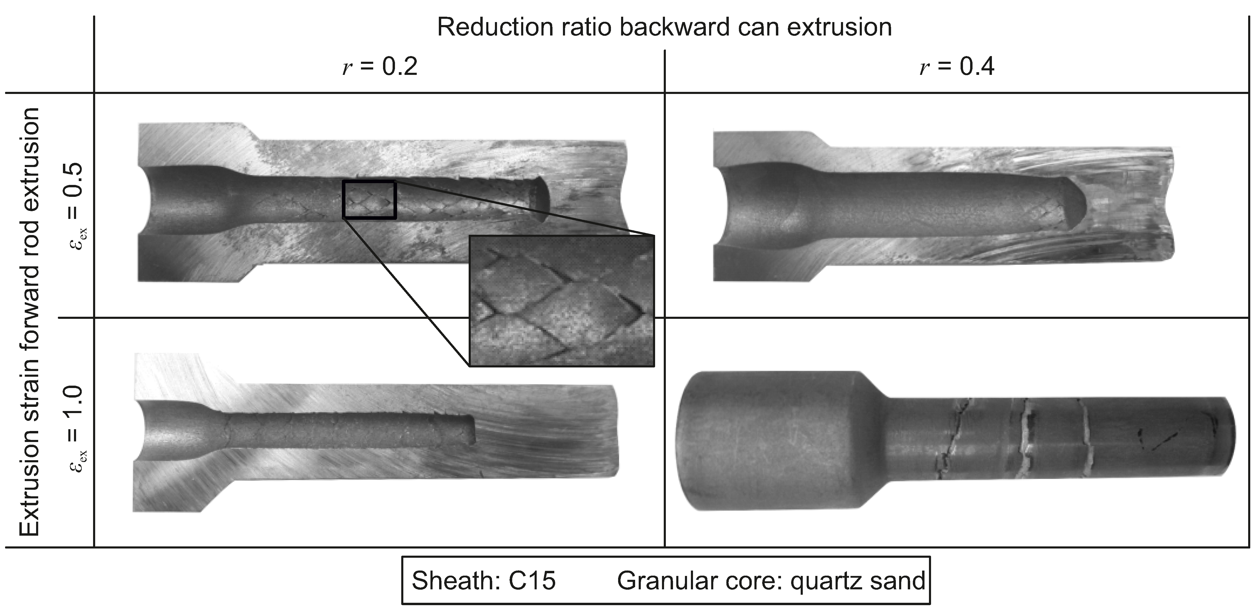
Figure 14.
Hollow shafts produced by forward rod extrusion of steel cup billets filled with quartz sand, cut open to reveal inner surface.
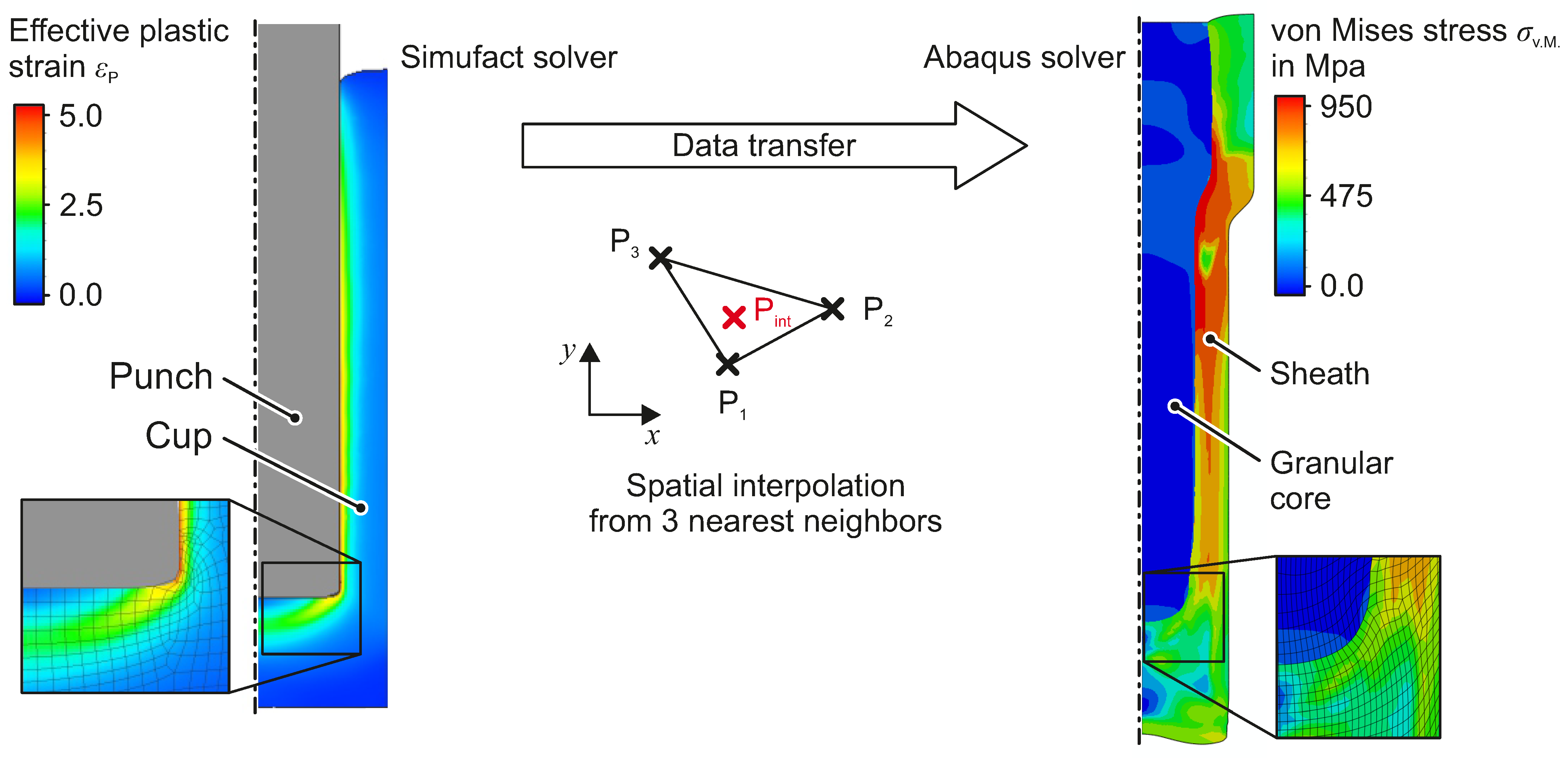
Figure 15.
Simulation model for the process chain of cold forging with granular medium based cores. Backward can extrusion is modelled using Simufact forming. The process step of forward rod extrusion is modelled using Abaqus. The data transfer between the two solvers is implemented by a Python script.
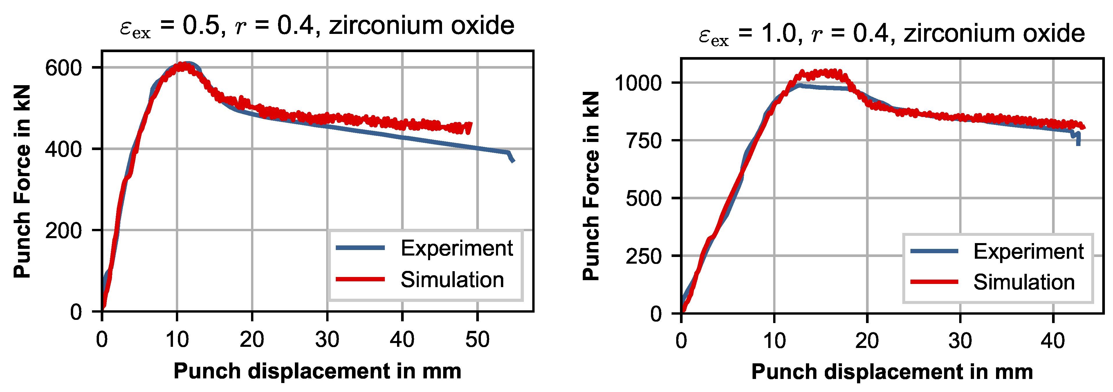
Figure 16.
Punch force measured in experiments and obtained from simulation of forward rod extrusion with zirconium oxide core.
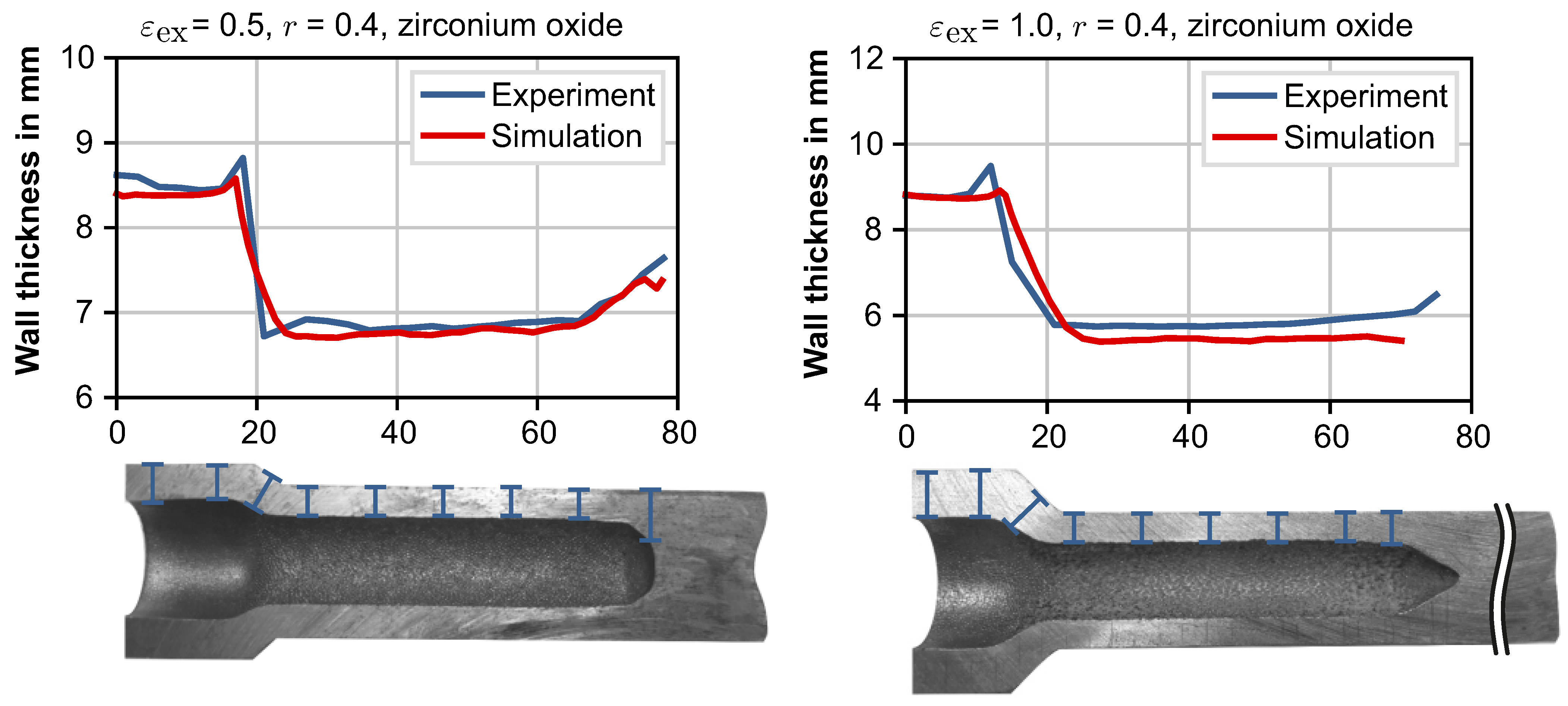
Figure 17.
Wall thicknesses measured in experiments and obtained by process simulations.
Figure 18.
Mass savings for substituting a solid steel shaft by composite shafts with aluminum core, magnesium core and hollow shafts with identical torsional stiffness.
Table 1.
Investigated parameters in composite cold forging with magnesium core billets.
| Varied Parameters |
|---|
| Reduction ratio r | 0.2 0.4 0.6 |
| (corresponding inner cup diameter) | (13.4 mm 19 mm 23.2 mm) |
| Extrusion strain | 0.3 0.5 0.7 1.0 1.2 1.5 |
| Fixed Parameters |
| Cup material | Steel C15 (1.0401) |
| Core material | Magnesium AZ31 |
| Inner cup surface treatment | Sandblasting |
| Billet diameter | 30 mm |
| Cup bottom thickness | 12 mm |
Table 2.
Investigated parameters in cold forging with granular media acting as lost cores.
| Varied Parameters |
|---|
| Reduction ratio r | 0.2 0.4 |
| (corresponding inner cup diameter) | (13.4 mm 19 mm ) |
| Extrusion strain | 0.5 1.0 |
| Core material | quartz sand zirconium oxide |
| Fixed Parameters |
| Cup material | Steel C15 (1.0401) |
| Inner cup surface treatment | none |
| Billet diameter | 30 mm |
| Cup bottom thickness | 12 mm |
Table 3.
Material parameters for (
a) C15 steel, identified by Kolpak [
18], and (
b) granular media, identified by Chen [
20].
| (a) Swift |
| C in MPa | | n | | | | |
| 738 | 0.128 | 0.162 | | | | |
| (b) Drucker-Prager-Cap |
| Material | | d in MPa | r | | a in MPa | b |
| Quartz sand | 47.2 | 1.02 | 0.1 | 0.48 | −44.66 | 2.313 |
| Zirc. oxide | 23.4 | 0.65 | 0.1 | 0.26 | −44.01 | 24.37 |
Table 4.
Characteristics of different core materials used in composite forward rod extrusion.
| Core Type | Advantages | Disadvantages | Potential Field of Application |
|---|
| Aluminum | High bond strength | Lowest lightweight potential | General lightweight design
for highly loaded parts |
| Magnesium | Damping properties | Low bond strength | UHCF applications |
| Granular | Highest lightweight potential | Indented inner surface | Lightweight design
for complex geometries |
| Publisher’s Note: MDPI stays neutral with regard to jurisdictional claims in published maps and institutional affiliations. |
© 2020 by the authors. Licensee MDPI, Basel, Switzerland. This article is an open access article distributed under the terms and conditions of the Creative Commons Attribution (CC BY) license (http://creativecommons.org/licenses/by/4.0/).


