Article

In Situ Characterization of the Effect of Twin-Microstructure Interactions on {1 0 1 2} Tension and {1 0 1 1} Contraction Twin Nucleation, Growth and Damage in Magnesium

by
William D. Russell
1,2,
Nicholas R. Bratton
1,2,
YubRaj Paudel
1,*,
Robert D. Moser
3,
Zackery B. McClelland
3,
Christopher D. Barrett
1,2,
Andrew L. Oppedal
1,2,
Wilburn R. Whittington
1,2,
Hongjoo Rhee
1,2,
Shiraz Mujahid
1,
Bhasker Paliwal
1,
Sven C. Vogel
4 and
Haitham El Kadiri
1,2,5,*
1
Center for Advanced Vehicular Systems, Mississippi State University, Mississippi State, MS 39762, USA
2
Department of Mechanical Engineering, Mississippi State University, Mississippi State, MS 39762, USA
3
U.S. Army Corps of Engineers, Engineer Research and Development Center, Vicksburg, MS 39180, USA
4
Materials Science & Technology Division, Los Alamos National Laboratory, Los Alamos, NM 87545, USA
5
School of Automotive Engineering, Université Internationale de Rabat, Rabat-Shore Rocade Rabat-Salé, Rabat 11103, Morocco
*
Authors to whom correspondence should be addressed.
Metals 2020, 10(11), 1403; https://doi.org/10.3390/met10111403
Submission received: 25 September 2020 / Revised: 15 October 2020 / Accepted: 16 October 2020 / Published: 22 October 2020

Abstract

:
Through in situ electron backscatter diffraction (EBSD) experiments, this paper uncovers dominant damage mechanisms in traditional magnesium alloys exhibiting deformation twinning. The findings emphasize the level of deleterious strain incompatibility induced by twin interaction with other deformation modes and microstructural defects. A double fiber obtained by plane-strain extrusion as a starting texture of AM30 magnesium alloy offered the opportunity to track deformation by EBSD in neighboring grains where some undergo profuse {1 0 1 2} twinning and others do not. For a tensile loading applied along extrusion transverse (ET) direction, those experiencing profuse twinning reveal a major effect of grain boundaries on non-Schmid behavior affecting twin variant selection and growth. Similarly, a neighboring grain, with its ⟨c⟩-axis oriented nearly perpendicular to tensile loading, showed an abnormally early nucleation of {1 0 1 1} contraction twins (2% strain) while the same {1 0 1 1} twin mode triggering under ⟨c⟩-axis uniaxial compression have higher value of critical resolved shear stress exceeding the values for pyramidal ⟨c + a⟩ dislocations. The difference in nucleation behavior of contraction vs. compression {1 0 1 1} twins is attributed to the hydrostatic stresses that promote the required atomic shuffles at the core of twinning disconnections.

Graphical Abstract

1. Introduction

The reduction of greenhouse gases and the reduced dependence on hydrocarbon-based fuels are of key priority worldwide. The United States, Canada, China, and the Euro-zone have engaged in a plan to reduce the mass of CO2 emitted by passenger vehicles a full 30% to 50% below current standards. Such tremendous improvements will require extensive vehicle mass reduction with lightweight materials allowing for a net fuel economy improvement in combustion engines and an increase in the range of electric vehicles, while maintaining/improving current standards for safety and crashworthiness. Two of the most attractive metals with potential to satisfy these conflicting demands, magnesium (Mg) and titanium (Ti) alloys, exhibit a hexagonal close-packed (HCP) crystal structure at room temperature [1]. While Ti is too expensive for most automotive applications, current structural applications of Mg alloys are limited to castings due to difficulties associated with forming wrought alloys [2].
The limitation in forming of Mg alloys is associated with the plastic anisotropy of a hexagonal lattice. The inability of Mg alloys to deform easily along the crystal 〈c〉-axis slip and satisfy the von Mises criterion of five independent deformation systems for polycrystalline plasticity stipulates plastic accommodation by deformation twins: {1 0 1 2} tension twins and {1 0 1 1} contraction twins. Studies have shown that profuse nucleation of {1 0 1 2} twins followed by twin interactions with other deformation modes and microstructural defects have led to asymmetry, anisotropy, and damage initiation in Mg alloys [3,4]. Likewise, {1 0 1 1} contraction twins are also associated with early damage nucleation in Mg alloys [5]. When a deformation twin nucleates at a grain boundary (GB), propagates across a grain, and reaches the opposite GB, the plastic shear brought about by this twin can be either accommodated by surface kinking, slip, or twinning at the GBs [6,7].
Accommodation effects by slip and kinking are of considerable importance to understand strain incompatibility induced by twinning. While kinking arises in the case where the twin emerges at the free surface, for example, single crystals, accommodation in polycrystals are mainly facilitated by means of a slip or another twin (interaction twins). If a GB has a low misorientation allowing the adjacent grain to have a high local resolved shear stress from the stress concentration ahead of shooting twin, twinning can be readily activated in the adjacent grain [8]. This is a particular case for sharp textures where twins could be observed traversing across multiple grains from one edge to another edge [9,10,11]. However, if the GB has a sufficiently high misorientation leading to a low local Schmid factor for twinning in the adjacent grain, which could arise in weak textures, slip is necessary or otherwise a crack may nucleate to drive fracture [12,13,14]. Crack nucleation at the termination of an incident twin meeting an obstacle twin has been actually reported as early as 1868 by Rose [15], who described “Rose channels”, or voids, formed by intersecting twins in calcite. These were later described by Priestner [16] as microcracks in body-centered cubic (BCC) metals (Figure 1), and by Sleeswyk [17,18,19] to explain ductile–brittle fracture transition in BCC iron through a complex emissary dislocation proposed mechanism. Twin-accommodation effects at GBs and twin boundaries (TBs) bear critical implications for damage initiation in HCP structures [20]. Recently, Zhang et al. [4] showed via molecular dynamics (MD) simulations that the openings of cracks in BCC crystal molybdenum at a GB into which a deformation twin impinges (Figure 2).
In general, even for largely unconstrained single crystal, plastic deformation carried by twinning is partly accommodated by kinking and/or slip [21,22,23]. Holden [21] observed that non-basal slip triggers in most cases to relax any strain incompatibility in pure metals. However, in the case of stronger alloys, such non-basal slip systems tend to be much harder to activate than the basal slip counterparts, which would promote hot stress spots and local fracture initiation. This explains why twinning is not as deleterious to ductility in a face-centered cubic (FCC) as compared to HCP metals, considering that the critical resolved shear stress (CRSS) remains the same for all active slip dislocations (practically one slip mode). Although the role of a twin-accommodation slip in plasticity was invoked and emphasized since the 1950s and 1960s, current crystal plasticity, and thus, continuum mechanics models still largely ignore it. The difficulty of activating the slip might be exacerbated by intergranular particles and solutes, so cracks may readily open at the termination of twin interactions in alloys as suggested by Remy [24,25]. Finally, all these events are compounded with classical effects of slip on strain incompatibility and thus localization. GBs are lattice orientation discontinuities over which strain incompatibility arises. Local phenomena are more pronounced in triple junctions and quadruple points where deformation is more than two grains influencing the effective lattice rotation.
From the macroscopic standpoint, if one assumes that twinning is responsible for the limited ductility of magnesium, it is not yet clear why ductility is still unacceptable for fibers loaded under a loading orientation where {1 0 1 2} tension twinning activity is minimized. For instance, when a basal texture is pulled normal to the fiber axis, prismatic 〈a〉 and pyramidal 〈c + a〉 slip should be the dominant deformation mechanisms. Although an improvement in total elongation is obtained, compared to the case of profuse twinning having a sigmoidal stress-strain curve (20% vs. 12%, respectively), necking does not take place and fracture occurs in a brittle-like fashion. One may argue that locally, twinning occurs because of slip-induced lattice rotations. However, the amount of rotation remains largely incapable of bringing a favorable orientation of {1 0 1 2} twinning. There are reports of {1 0 1 1} [26,27] (also {1 0 1 3} and {1 0 2 4}) formation in magnesium alloys that show deleterious effect in ductility [5,28]. Most of these reports suggest the higher values of CRSS for {1 0 1 1} such that they would only appear inside {1 0 1 2} twins during the saturation stage of stress after the rapid hardening correlated with profuse twinning [27].
In crystal plasticity simulations of pure magnesium, Oppedal et al. [29] used a CRSS value of 181 MPa for {1 0 1 1} twinning compared to 11 MPa for basal 〈a〉, 15 MPa for {1 0 1 2} twinning, 30 MPa for prismatic 〈a〉, and 50 MPa for the very hard second order pyramidal 〈c + a〉. In general, {1 0 1 1} twinning has a high Schmid factor in this loading orientation but because of its high CRSS, it is not expected to form at the relatively low saturation stress levels attained during tension normal to the basal fiber. Apart from the selection of deformation modes, studies show the competition within the twin variants of a tensile or a compression twin to accommodate deformation within a grain [30,31,32]. Researchers have associated twin variant selections to strain accommodation at the grain boundary, hydrostatic stresses, and twinning dissociation energies [33,34,35].
In an effort to bring experimental evidence and elucidate the dominant damage mechanisms involving twinning in HCP metals, we performed fractographical analysis as well as microstructural analysis on the interactions between twins with other deformation modes and microstructural defects. An in situ and interrupted electron backscatter diffraction characterization is performed on flats formed in a plane-strain constraint found in an extruded AM30 magnesium alloy “crush rail” showing a double-fiber texture. This texture allowed both profuse and no twinning in neighboring grains under the same uniaxial tension. This work closely studies the damage caused by various twin variant interactions as well as parsing their effect on texture evolution within each grain. Furthermore, double-fiber texture with grains, which have favorable Schmid values for twinning and are surrounded by grains prohibiting twinning, provided us an opportunity to study the effect of GB strain-accommodation on twin variant selections within a grain and damage initiation along the GBs.

2. Methods and Materials

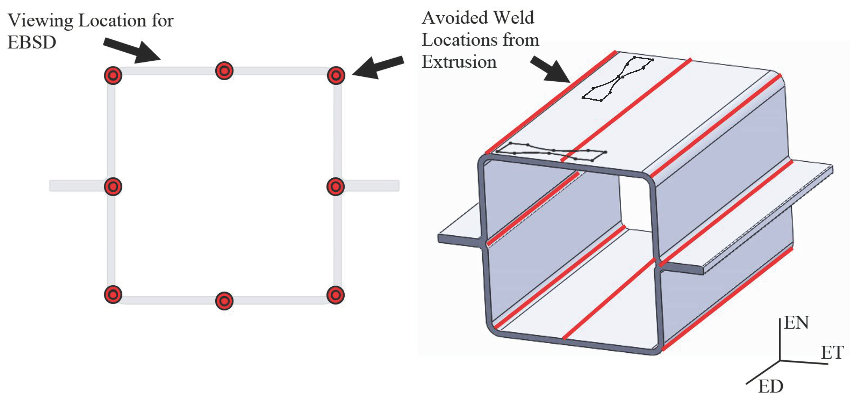
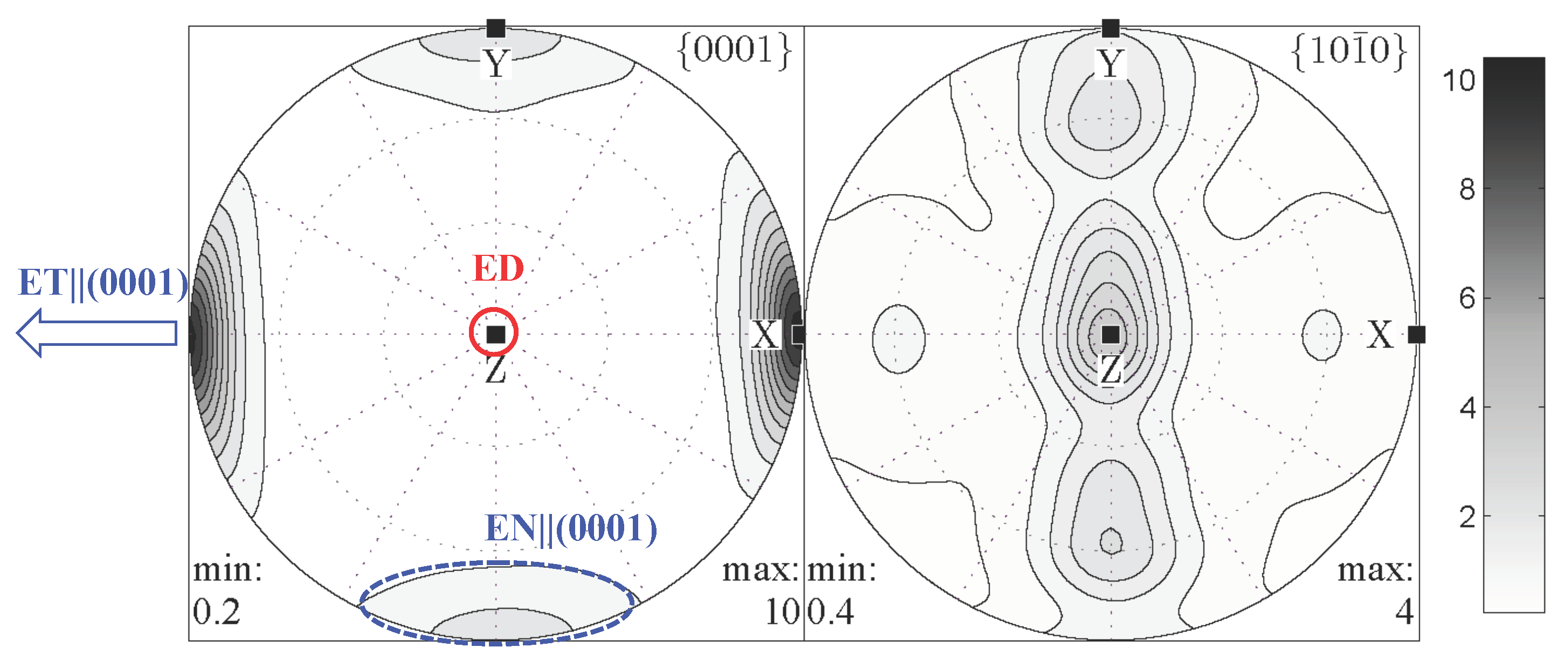
2.1. Experimental Procedure

Magnesium alloy AM30 with a chemical composition (wt %) of 2.83 Al, 0.386 Mn, 0.0037 Zn, 0.03 Fe, <0.0015 Ni, <0.0005 Cu, balance Mg was the material of this study. Extrusion of the AM30 alloy was performed by Timminco. The process began with pre-extrusion to bring down the diameter of the cast billet from a 450 to 230 mm diameter cylinder through an extrusion press that ran up to a maximum pressure of 22 MPa and then pushed the 230 mm billet through the final die at 16.5 MPa. The entrance and the exit temperature were around 440 and 540 °C, respectively. The ram speed for the extrusion was about 1.3 mm s−1, while the extrusion speed was about 45 mm s−1. The extrusion ratio was 35.26:1. Lastly, the billet was extruded into the final shape, which corresponded to a hollow tube in “double-hat” like shape, known as a “crush rail” (Figure 3). This “crush rail” showed a texture that has a strong basal pole aligned with the in-plane direction of the sheet normal to the extrusion direction (extrusion traverse, or ET), and a weak basal texture component in the normal direction of the sheet (EN) (Figure 4). As such, under tension along ET (resp. EN), several grains belonging to the E T | | ( 0 0 0 1 ) fiber (resp. E N | | ( 0 0 0 1 ) fiber), would be subject to the formation of all six {1 0 1 2} twin variants contributing to their very large Schmid factor (0.499). While grains belonging to the E N | | ( 0 0 0 1 ) (resp. E T | | ( 0 0 0 1 ) fiber) fiber will experience favorable conditions for slip mechanisms to take place exclusively and perhaps {1 0 1 1} twins if enough stress is attained.

2.2. Fractography

Specimens machined in extrusion (ED) and extrusion transverse directions (ET) were planar ground using 4000 grit silicon carbide paper and then electropolished to a pristine finish. Through interrupted electron backscatter diffraction (EBSD) analysis on specific regions, the evolution of deformation and damage was studied. Figure 5 shows stress–strain curves obtained at 0.001 s−1 strain rate when the specimens were taken to full fracture, which delineate traditional anisotropy of magnesium that is associated with basal and rod fiber textures. Under a tensile load in the ED direction, {1 0 1 2} twinning is nearly non-existent yielding to parabolic stress–strain behavior, while under ET all the grains belonging to the strong E T | | ( 0 0 0 1 ) fiber experience profuse {1 0 1 2} twinning eventuating to a sigmoidal curve with very rapid hardening. After failure, fractographic analyses were conducted using a Zeiss Supra 40 field emission scanning electron microscope (FEG-SEM) to determine the overall causation of failure.

2.3. In Situ and Interrupted Electron Backscatter Diffraction (EBSD)

The interrupted EBSD characterization and collection were performed with a FEG-SEM equipped with orientation image microscopy (OIM, EDAX TSL) at a step size of 100 nm on large regions of the samples. These EBSD analyses were completed using the commercially available TSL OIM analysis software from EDAX. Neutron diffraction texture analysis was conducted with the HIPPO neutron time-of-flight diffractometer at LANSCE [37]. HIPPO consisted, at the time of the data collection, of 1320 3He detector tubes arranged on 30 panels on three rings, covering 14.2% of 4π steradian (sr) for a single rotation and 44.5% with four rotations [38]. The sample was glued on a sample holder, which was loaded on a robotic sample changer [39]. Beam collimation was 10 mm in diameter and count times were 10 min per rotation. The diffraction data were analyzed using the Rietveld method for the 120 diffraction histograms collected for four sample rotations of 0°, 45°, 67.5° and 90° around the vertical axis following procedures described in Wenk et al. [40]. The pole figure data were imported into MTEX [41] for further ODF (orientation distribution function) analysis. Intermittent monotonic tension tests were performed using an Instron 8856 universal test frame at a quasi-static strain rate (0.001 s−1).
Most of the observations were conducted on sections normal to ET. The specimen was taken from the “crush rail” in such a way to avoid irregular texture created by welding in the extrusion process. Two contiguous areas of interest (AOI) as shown in the initial microstructure of Figure 6 were identified that are expected to show very different levels of twinning (Region AOI 1 and Region AOI 2). AOI 1 is composed of three primary grains all of which prescribe to the [1 1 2 0] orientation with the 〈c〉-axis along the line of tension, and as such favorable for {1 0 1 2} twinning (belonging to E T | | ( 0 0 0 1 ) fiber). AOI 2 is also composed of the three primary grains showing a [0 0 0 2] basal texture meaning the 〈c〉-axis is perpendicular to the loading direction (belonging to E N | | ( 0 0 0 1 ) fiber). This region should experience a dominance of slip deformation mechanisms, specifically basal 〈a〉, prismatic 〈a〉, and pyramidal 〈c + a〉 [36].

3. Results and Discussion

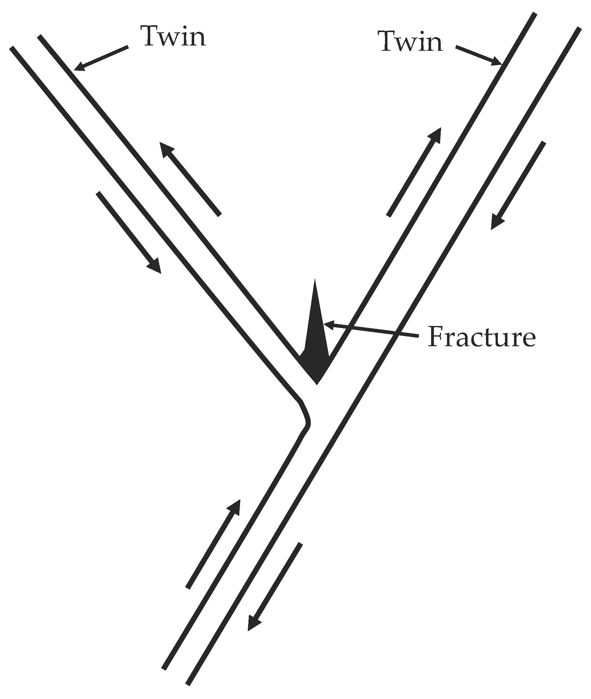
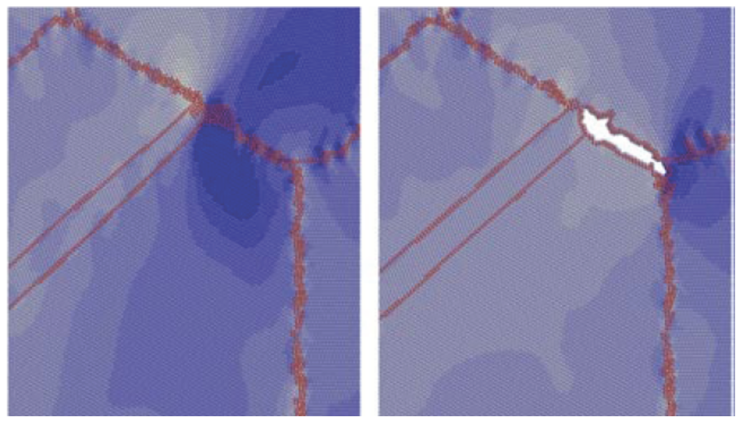
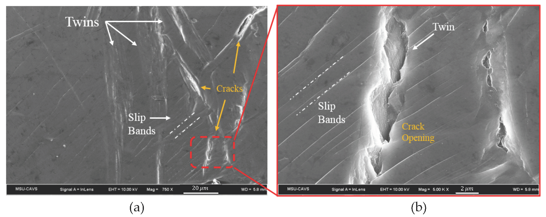
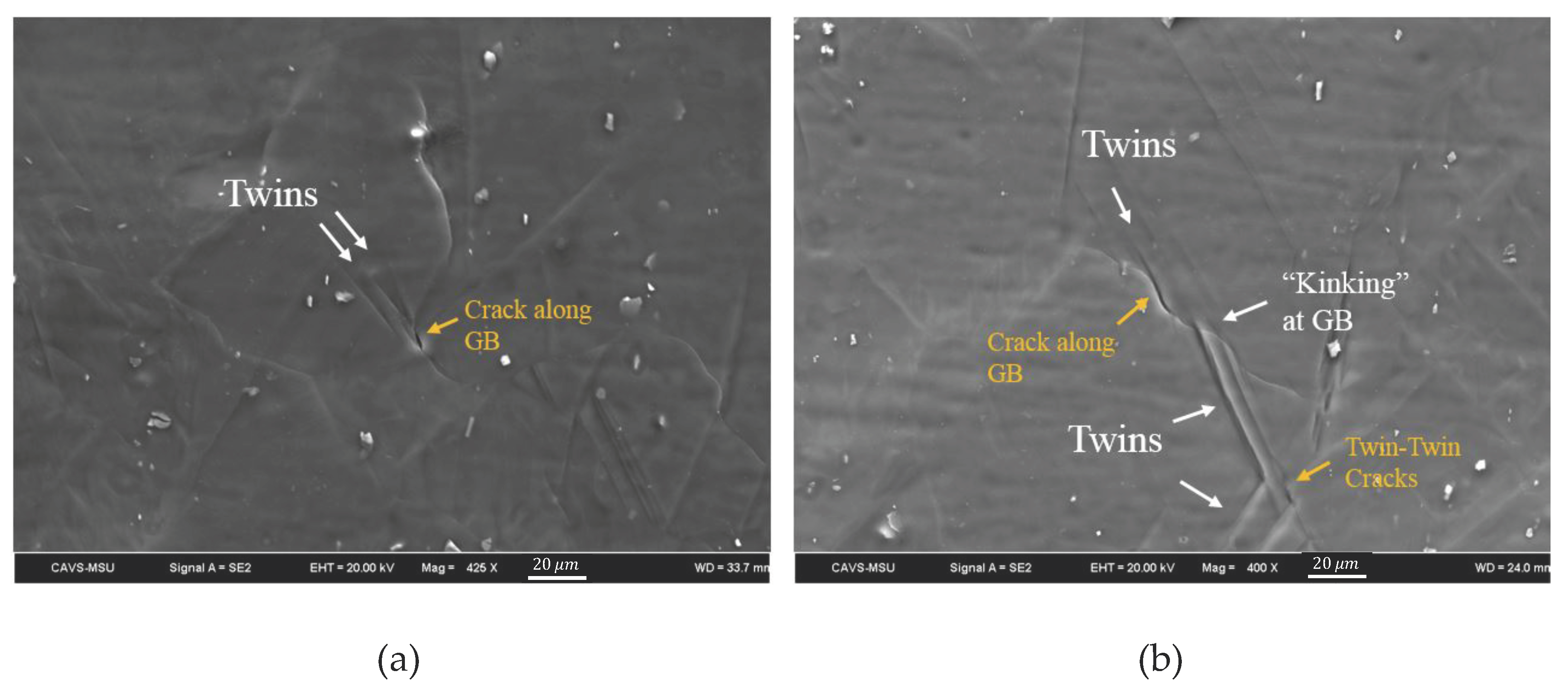
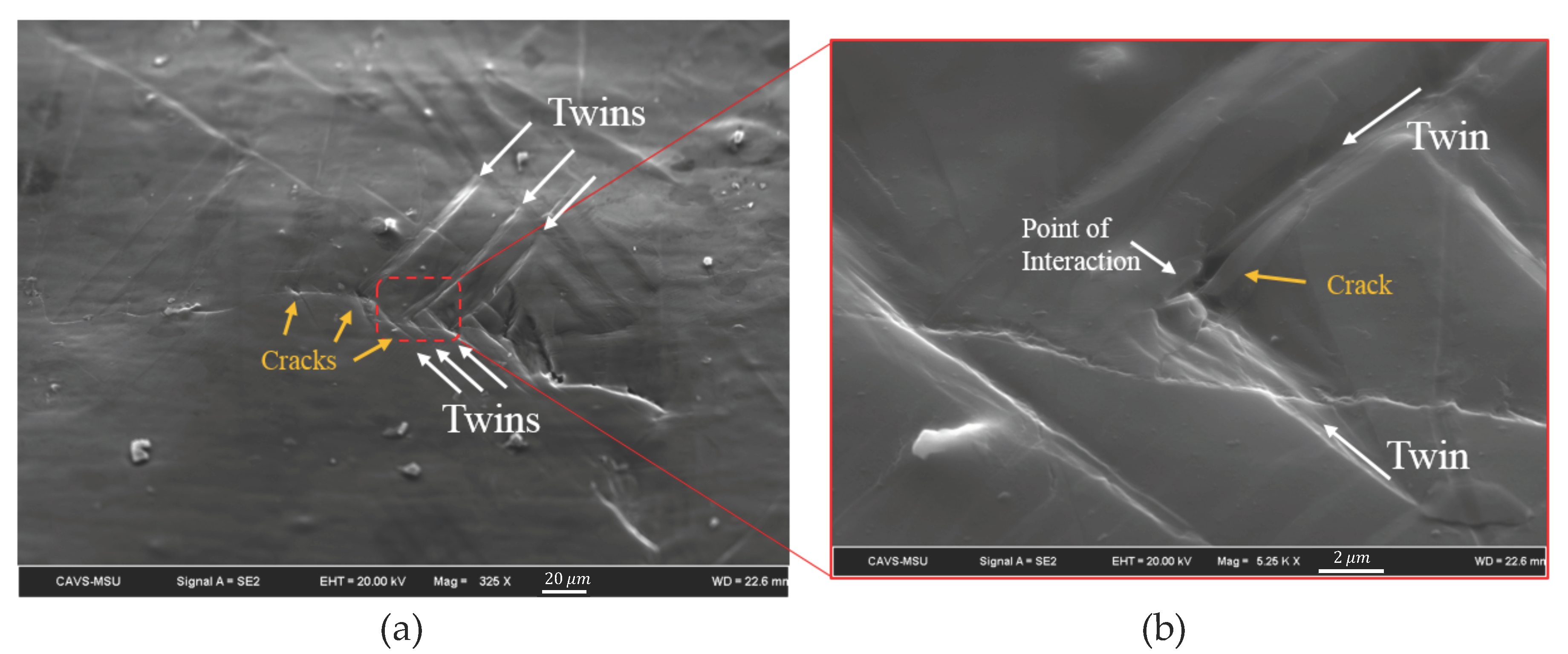
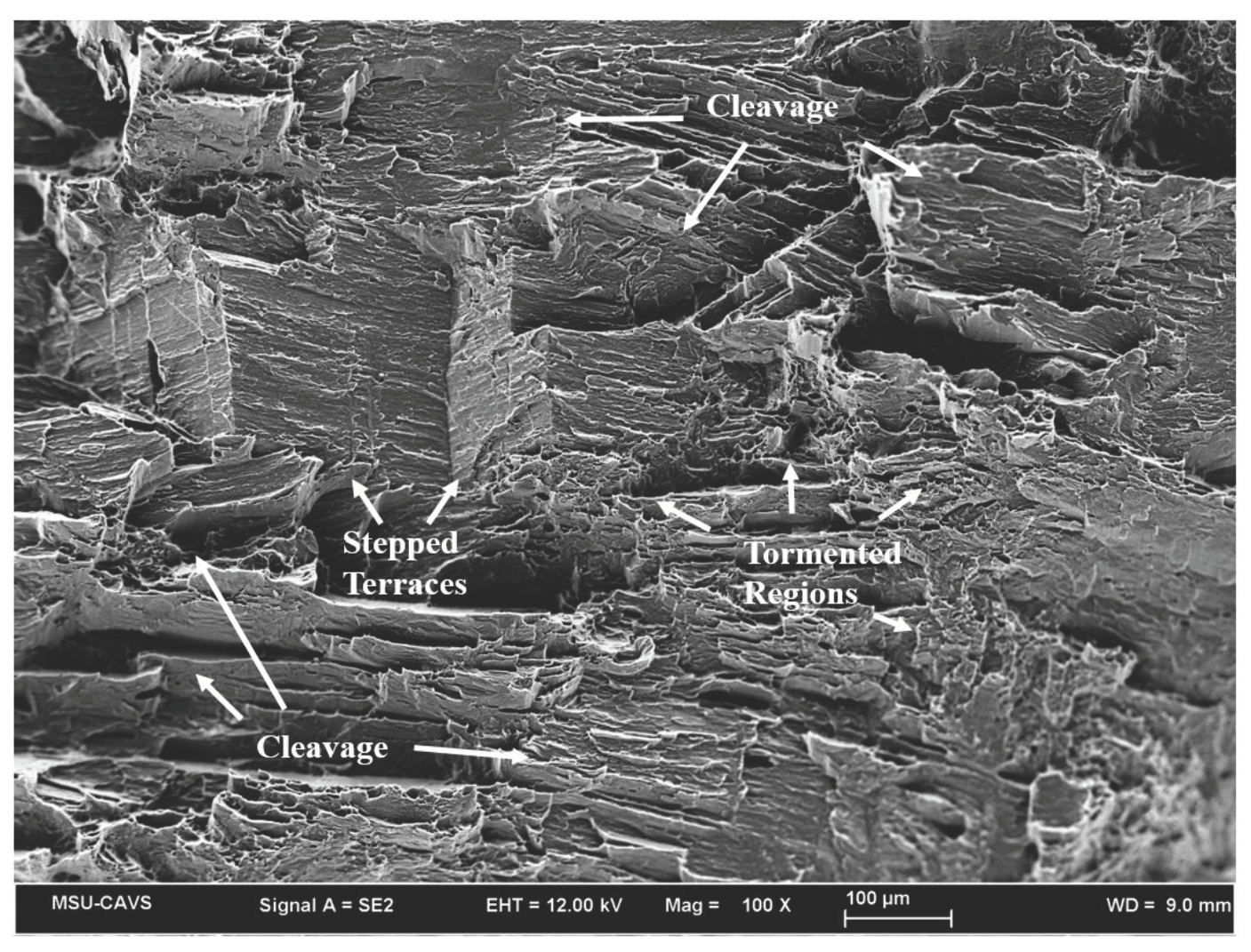
3.1. Fractographic Analysis of Twin-Interactions Induced Cracks

Coupled EBSD and FEG-SEM micrographic characterization at different strain levels revealed cracks nucleating at the intersection between two intersecting {1 0 1 2} twins, a twin and slip bands, and twin and grain boundaries. Figure 7, Figure 8 and Figure 9 depict tension twin interactions with slip, GBs and other twins, respectively. In all these cases, the macroscopic SF of the twins implicated in damage was low and their growth was sluggish.
For the case of slip–twin interaction (Figure 7), one possible mechanism behind crack nucleation is the difficulty for the twin to facet or form a disconnection as a dislocation meets the interface [42,43,44,45,46]. This would lead to an accumulation of dislocations and potential slip bands that create strain incompatibility and this hots spots inside the twin domains. These phenomena could be exacerbated by the transmutation effect, which would increase the density of sessile dislocations [47].
Figure 7 shows the formation of micro-cracks due to interactions between tensile twins and basal slip bands. The slip–twin interaction creates a strain incompatibility at the twin interface, which leads to high stress concentration zones or hot spot regions. The occurrence and distribution of slip bands along with the glide of interstitial type dipole loops creates a vacancy, which in turn cause crack nucleation in slip–twin interfaces [48]. The interactions between basal dislocation and {1 0 1 2} twin could proceed in three different ways: (i) direct transmission that could be seen as mere cross slip of this dislocation into the basal plane of the twin, (ii) indirect transfer characterized by transmutation of the initial dislocation into a sessile [c]-containing dislocation on the prismatic plane leaving a disconnection along the boundary, and (iii) activation of non-basal slips [49]. The formation of sessile dislocation due to interaction between a slip–twin boundary, disconnections left in the interface, and pile ups of transmitted dislocation are consistent with the initiation of cracks [50].
For the case of cracks nucleating at the twin-GB intersections revealed in Figure 8, one plausible explanation is the difficulty to accommodate strain at the GB due to the unfavorable orientation of the next grain to accommodate the local stress by easy slip. Propagating twins move through the grain until they reach the boundary at which the stress field carried ahead of the twin tip must be accommodated. In the case of a grain orientation favorable for twinning on any plane variant, which is a typical case of sharp textures, a new twin is formed in the next grain, giving rise to autocatalytic twinning. However, if the orientation requires activation of hard slip, i.e., hard neighboring grains, the twin may cease to propagate lengthwise beyond the GB. The twinning dislocations lying on the top of each other, which has been driving this propagation will pile-up at the GB, create a region of high stress concentration that would continue to exacerbate with further strain. As such, depending on the orientation of neighboring grains (i.e., GB misorientations) twin-GB regions of intersection are prone to hot spots and damage nucleation.
Figure 9 reveals cracks nucleating exactly at twin–twin intersections, which has been reported in early literature for BCC systems [24,25,51,52,53]. When an incident twin encounters an obstacle twin, the strain can be accommodated by either of the following mechanisms: (i) retwinning of the obstacle twin, (ii) slip in the incident or obstacle twin, or (iii) detwinning of the incident twin [17,51,54]. As described by Beyerlein and Tomé [55], grains with multivariant twinning are more likely to rapidly strain harden due to the fact of lower CRSS of twin propagation compared to nucleation. Intersecting twins have been actually associated with fractures in the literature since 1957 [56,57,58] or even earlier as noted in these papers. Further evidence of twins variants impeding the variants growth and building strain until a crack nucleation is observed in AOI 1 and discussed in the following subsection. Based on the local crystallography, two types of twin–twin interactions could occur depending on whether the two twin variants share the same 〈1 1 2 0〉 zone axis or not. In the first case, one twin does not transmit across another, whereas for the latter type, the twin could transmit through under proper conditions of loading. However, for most cases the former type of twin–twin interaction occurs with quilted-looking twin structures consisting of boundary dislocations [59]. This phenomenon might be exacerbated in the case of low SF twins, as their lack of thickening rate might promote strong strain incompatibilities at the triple junction and the likelihood of debonding between the two twins.
Double twinning has been used to describe multifold twinning within an original twin as early as the 1960s [60]. Within Mg, double twinning enhances damage and commonly occurs with {1 0 1 1} twins forming within a {1 0 1 2} tensile twin [5,26,27,61,62,63,64,65]. However, in the case of this study, contraction twins are found to form at relatively low stresses and are associated with double twinning. In basal textured AM30 alloy, {1 0 1 1}-{1 0 1 2} double twins were reported to be preferential sites for fracture initiation. Also, the sharp surface steps related to these double twins were associated with the formation of a crack [66,67]. This is evident in the massive cracks formed in Figure 10 and Figure 11.
Notice the contraction twins are located in a parent grain and did not form through double twinning. Figure 11 shows the misorientation of the twin with the parent to be 56° and not the 38° of (1 2 1 0) expected for double twinning [5,62]. In addition, the size and shape are that of a contraction twin, while a double twin would fill the silhouette of the original twin.
Contraction twin induced damage could be explained by the inability of a slip to penetrate the hard contraction twin boundary, creating large areas of cleavage and stepped terraces within the fracture surface commonly related to brittle failure (Figure 12). The tormented areas occasionally observed in the fracture surface are attributed to slip deformation around the twin and grain boundaries and are commonly related to a ductile failure.

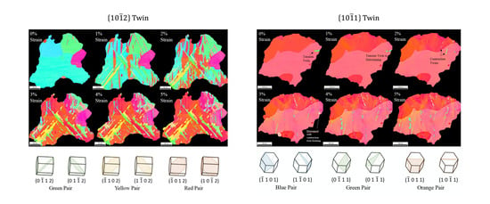
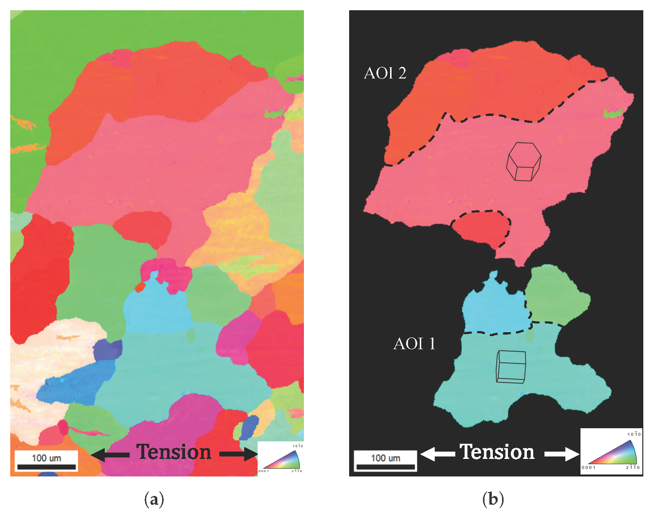
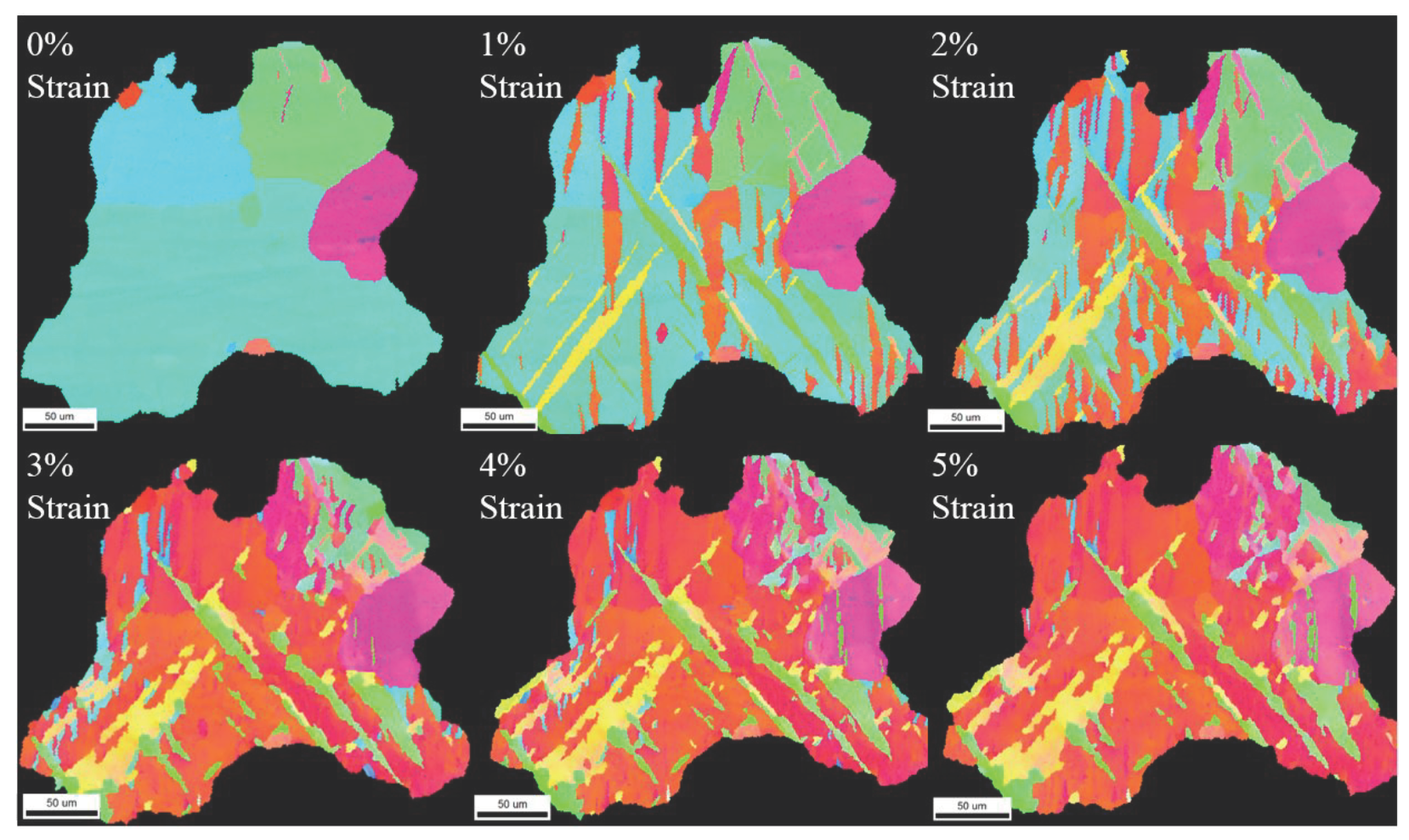
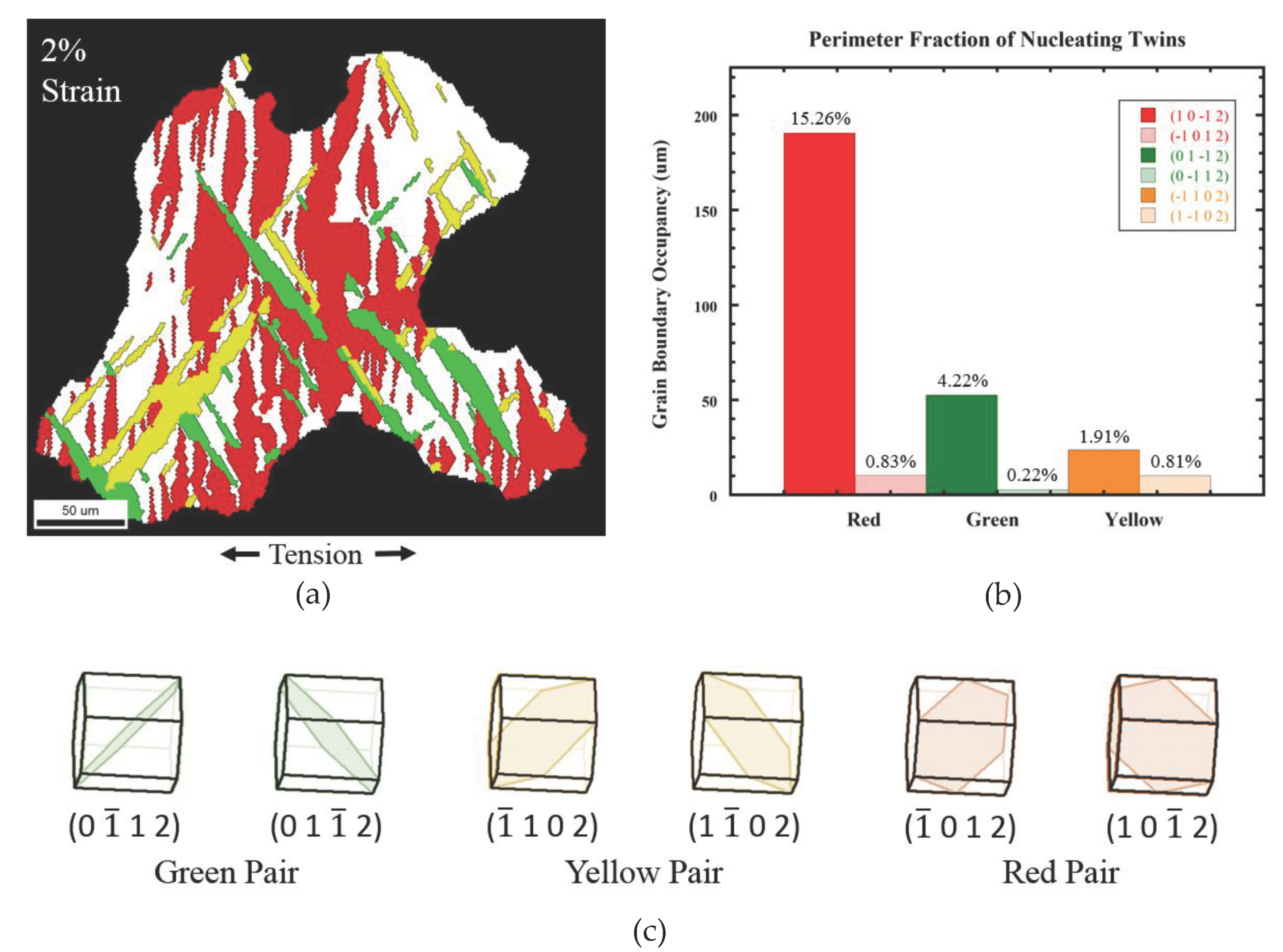
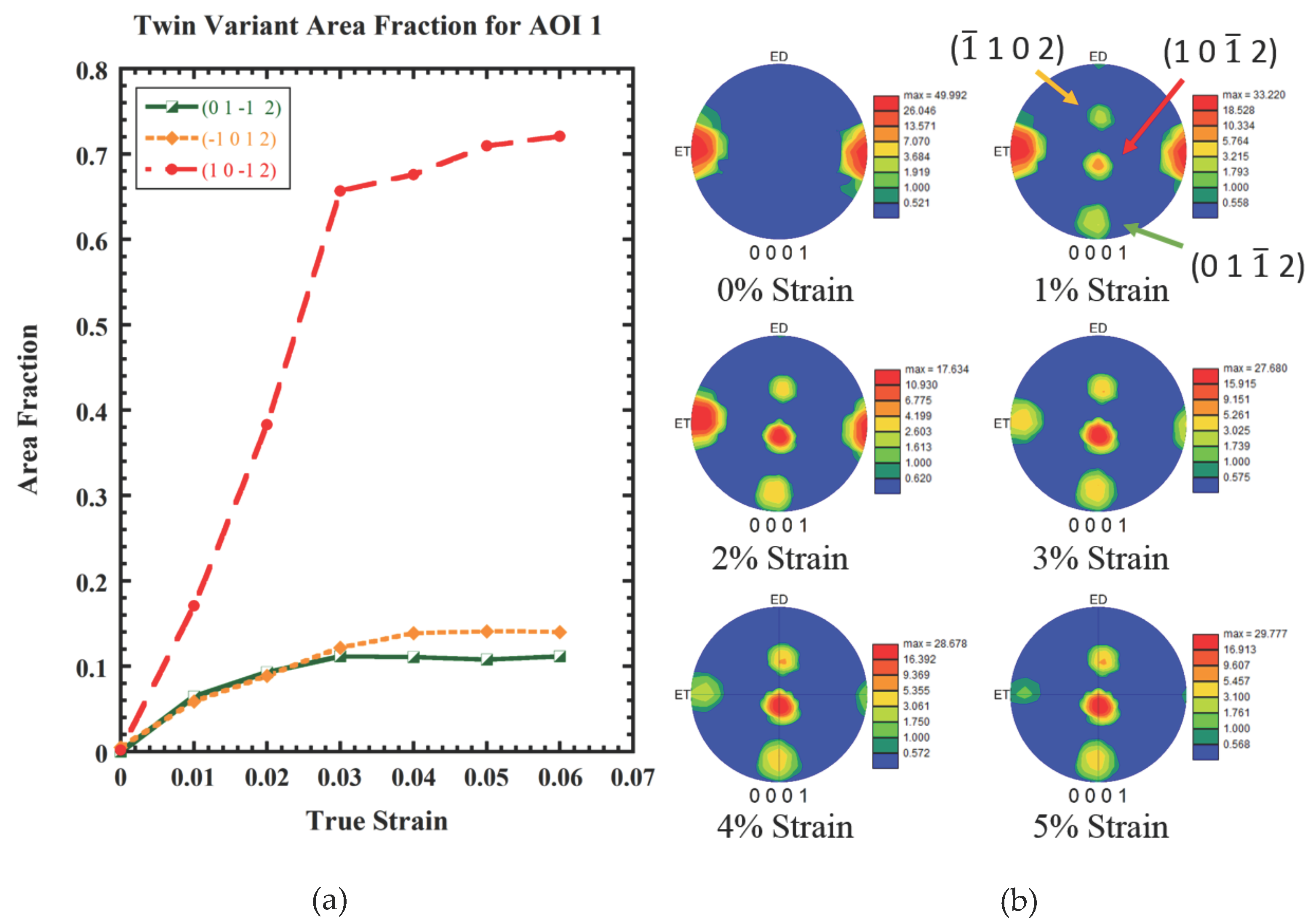
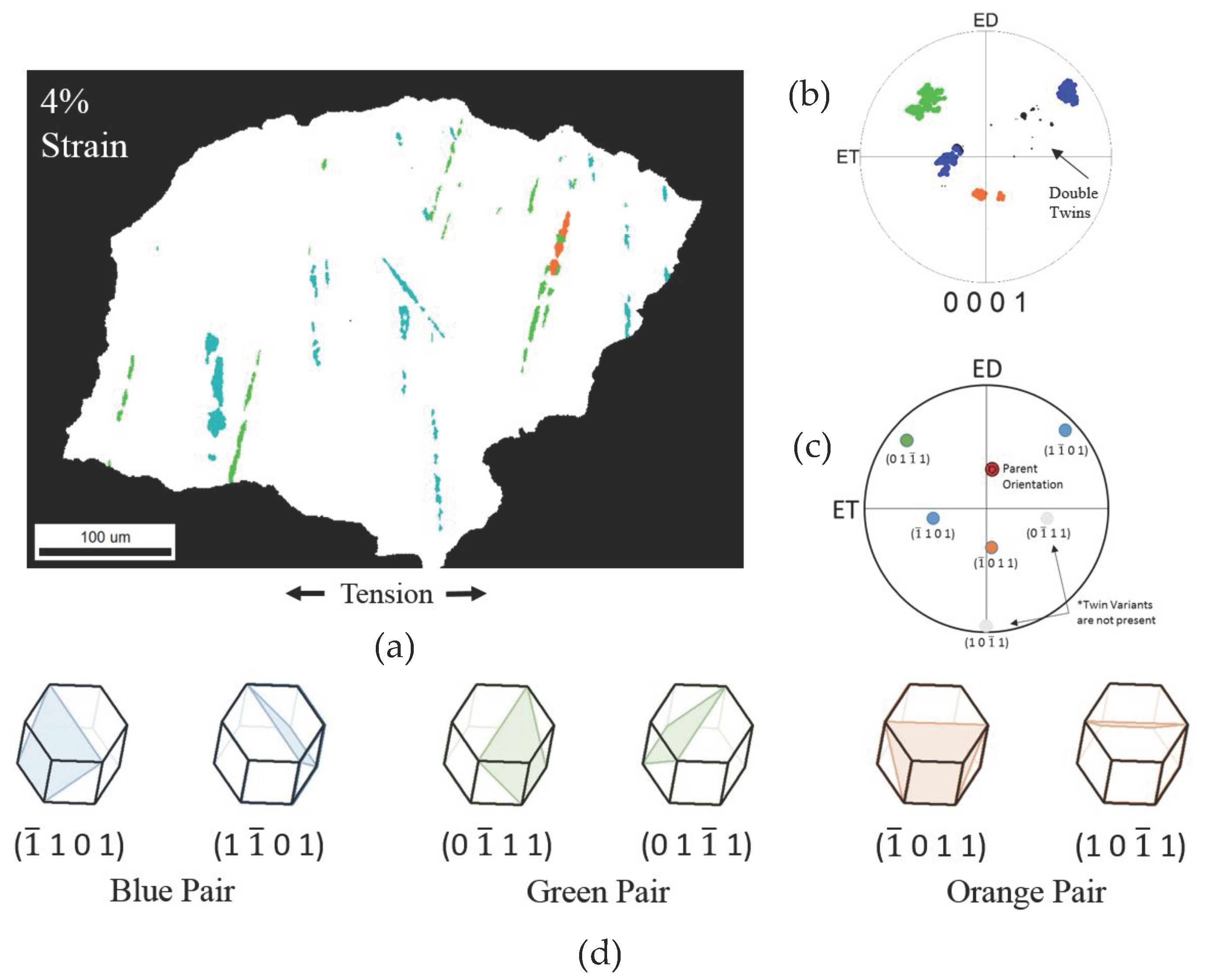
3.2. Interrupted EBSD Characterization in AOI 1

Figure 13 shows that AOI 1 readily experiences {1 0 1 2} tensile twinning caused by the extension of the 〈c〉-axis. Resolved Shear Stress (RSS) is commonly used to determine the likelihood of elevation of stress through slip or twins. The RSS is dependent on the Schmid factor (SF), 0 | S F | < 0.5 , of slip or twin plane of interest and the applied stress (σapp) of the material [29] (Table 1 describes the RSS of possible slip and twin systems). With all variants of {1 0 1 2} tensile twins having near maximum SF values, all variants are equally likely to be present in the EBSD micro textures.
When determining the twin variants, multiple factors are checked to confirm a twin variant. The simplest of these is boundary misorientation of twin and parent. In the case of all twins present, the misorientation is found to be 86° ± 8°. We also know that the 〈c〉-axis of the parent grain is in line with the loading direction allowing extension of the 〈c〉-axis, which promotes tensile twins. With evidence of confirmed tensile twins, we specified the Miller–Bravais indices of each twin based on a reference frame choice. The data from the EBSD analysis is used to create an orientation map, which highlights similar areas of lattice orientation based on the angle of the 〈c〉-axis. This map is shown in Figure 14 alongside the twin planes of the {1 0 1 2} system. The six twin variants found in the {1 0 1 2} system are made up of three distinct twin pairs and are highlighted as such in Figure 14. Each orientation of the present twins was used to calculate the SF of each twin plane. The average SF for each twin pair under a non-idealized [1 0 1 3 0] loading is shown in Table 2.
Incremental ET tensile tests of the AM30 with interrupted EBSD scans show the nucleation and progression of twins in AOI 1 (Figure 13). At 0% strain, very small {1 0 1 2} tensile twins were observed in the top right grain of AOI 1. The twins likely nucleated after grinding and polishing and their orientations are found to have a Schmid factor of SF = 0.43. This further provides an opportunity to discuss on twin–twin interaction effects within a single grain. While the other two grains are engulfed by tension twin at 3%, the top right grain only has half of the region covered by twin. The pre-existing twin blocks the growth of the red twin across the other half of this grain. Ultimately, twin nucleates and grows from the grain boundary with the right-bottom grain. The stress–strain relationship is commonly categorized by three regimes. The first regime represents the elastic portion of the response while the second encompasses the plastic strain leading to an inflection point in this case, the transition from twin nucleation dominated to twin growth dominated strain accommodation and the final regime represents the continuation of plastic deformation until failure. Within Regime I of the strain relationship twins readily nucleate from relatively high misorientation GBs before 1% strain could have been reached. Although six tensile twin variants are present, a dominant variant of each distinct pair present is conspicuous. This was associated by the ability to nucleate at all possible sites while the recessive variant nucleates from other twin boundaries. The dominant variant of each pair is easily distinguished in the pole figures of Figure 15b.
To determine the effect of twin nucleation on growth, we measured the GB perimeter fraction at which each twin variant nucleated with respect to the overall GB length. Figure 14b shows a plot of this tendency, which outlines a noticeable advantage of the (1 0 1 2) variant. Coupled with twin–twin interactions between the (0 1 1 2) and (1 1 0 2) variant pairs (green and yellow), stunting twin growth, enhanced nucleation at the GB allowed the (1 0 1 2) variant pair (red) to dominant overall twinning in AOI 1. By 5% strain, 97.3% of the parent grain has twinned. The twin variant area fractions are plotted in Figure 15.
The active tensile twins are composed of three distinct pairs. In Figure 14a, the tensile twin variants are highlighted in pairs with the respective colors of green yellow and red and further crystallographically determined in Figure 14c. This maps the twins by their orientation relative to each other instead of a global orientation given by the inverse pole figure. By doing so, all variants are easily distinguished at each strain level without confusing between new nuclei and twin thickening. Figure 14b plots each of the variants’ nucleation occupancy in the GB at 1% strain. It is important to note that as soon as the strain reached 1%, nucleation nearly ceased and twin fraction dominantly increased by twin thickening. Therefore, the (1 0 1 2) variant occupies the majority of GB restricting growth of the (0 1 1 2) and (1 0 1 2) twin variants. In fact, so few of the recessive variants occupy the GB, their growth is nearly negligible and mostly relies on forming from other twin boundaries.
Even though the red (1 0 1 2) variant pair had a lower Schmid Factor compared to the yellow (1 1 0 2) and green (0 1 1 2) variant pairs, they continued to engulf the parent grain while the yellow and green variants grew comparatively little after nucleation. This is thought to be an effect of grain boundary enhanced disconnection nucleation. In fact, the red (1 0 1 2) variant pair had a chance to thicken along the grain boundary segments of the grain, which is clearly correlated to the much higher thickness of these twin variants as they propagate along the grain boundary (Figure 14a). The other yellow and green variants were engulfed away from the grain boundary and thus were subject to substantial twin–twin interactions. Likewise, the pole figures in Figure 14b show that noticeable advantage of (1 0 1 2) twin variant can be the effect of a free surface on twin nucleation and growth. The pole for (1 0 1 2) variant is aligned towards the free surface compared to other twin variants, thus the free surface provides easy stress relief compared to the grain boundaries [68]. The EBSD micrographs provide a two-dimensional view of a three-dimensional twin with limited information on neighboring grain boundary effects. The understanding of the effect of neighboring grain boundaries on twin nucleation, propagation, and growth demands further research with three-dimensional observation of a twin through atomistics and modeling.

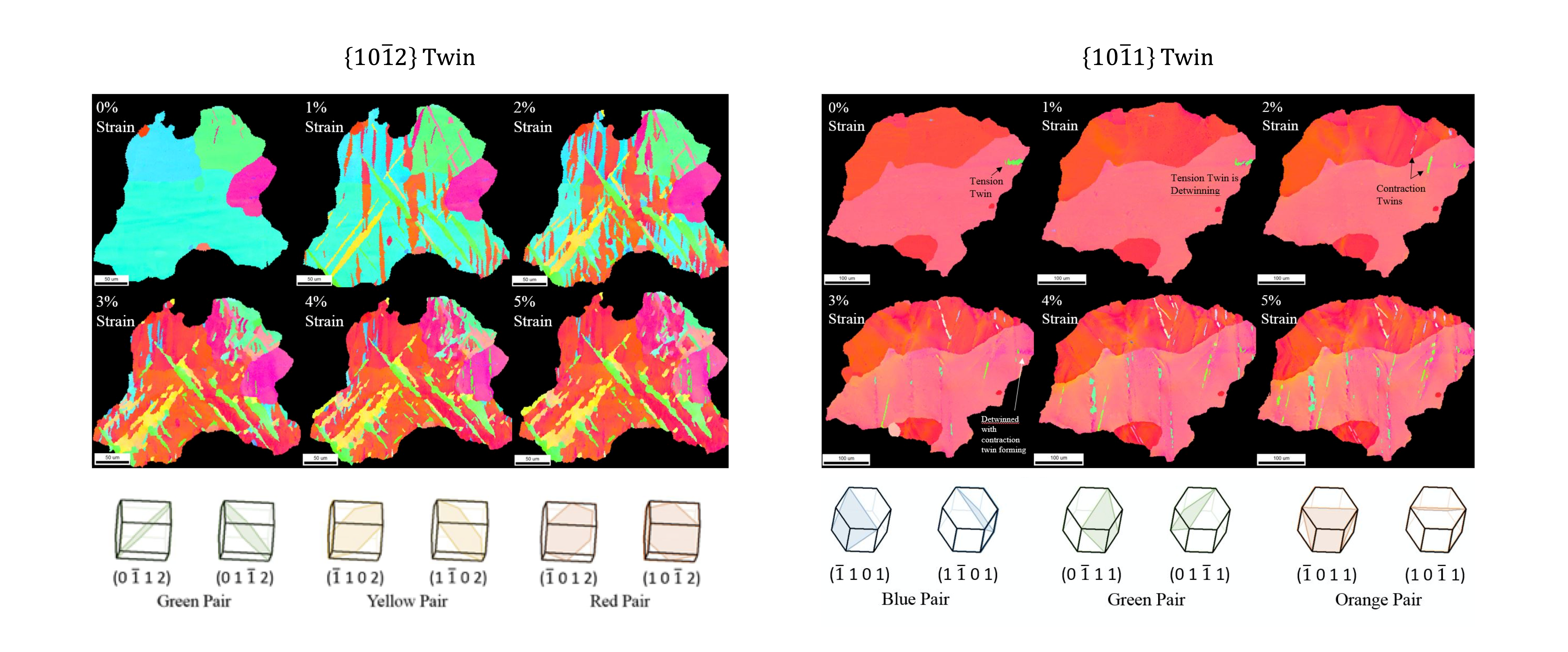
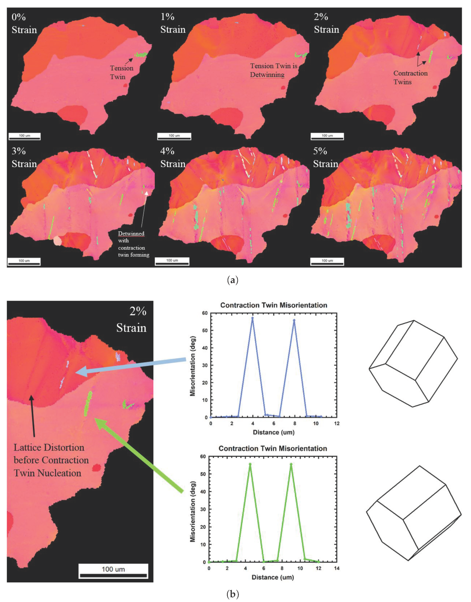
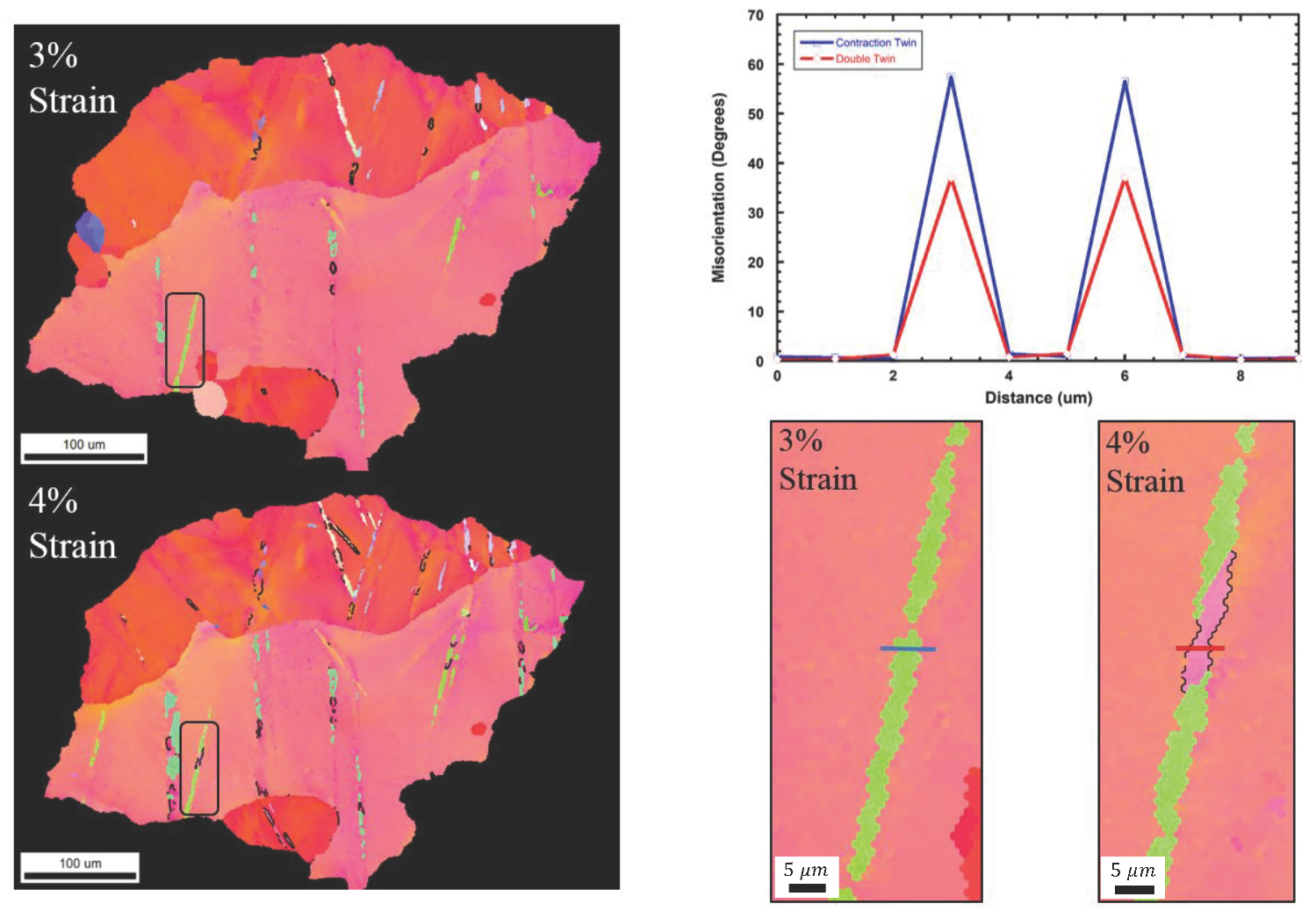
3.3. Characterization of Contraction Twinning in AOI 2

The second area of interest has a very different orientation compared to AOI 1. AOI 2 is composed of the three primary grains with a basal orientation (0 0 0 1). This orientation belongs to the weak texture of the double-fiber. The basal orientation aligns the 〈c〉-axis perpendicular to the loading direction, which leads to contraction of the 〈c〉-axis.
Figure 16 shows a schematic allowing to compare the symmetric pair of in-plane compression (IPC) of ED leading to {1 0 1 1} compression twin and [2 1 1 0] tension of ET leading to {1 0 1 1} contraction twinning. IPC experiences a linear stress compressing the 〈c〉-axis resulting in a net loss of volume, while [2 1 1 0] tension experiences complex hydrostatic stress with maximum compression acting on the center plane and maximum extension occurring along the loading axis. This results in a net gain in volume, which would aid shuffles and thus nucleate {1 0 1 1} twinning.
Compression twins {1 0 1 1} and shear bands, formed from compression twins, have been noted for failure in plane-strain compression [69]. Compression twins usually remain as thin and needle-like lamellae, a fact that was attributed to the low mobility of twinning disconnections due to the step height and complexity of atomic shuffling requirements [70]. The formation of compression twins is believed to occur at relatively high stress levels due to their very large CRSS [29]. Although compression twins and contraction twins are exactly of the same crystallographic nature, {1 0 1 1} [1 0 1 2], contraction twins in this study have been observed to nucleate at substantially lower CRSS, well below previously reported values in the literature when the 〈c〉-axis was under compression, not contraction.
The progression of damage in AOI 2 is shown in Figure 17 and, surprisingly, thin needle-like structures are nucleating at strains as low as 2%. At 0% strain, a tensile twin has formed likely due to handling of the specimen as the twin detwins with increasing strain. Since the focus in this region is to study contraction twinning and the small pre-existing tension twin has no effects on the nucleation or growth of the contraction twin, the effects of the tension twin is neglected. By 2% strain, contraction twins with SF of 0.209 and 0.448 have formed, while there is evidence of another about to nucleate. By 5% strain, multiple contraction twins are formed and large distortions can be observed within the parent grain. Like tensile twins, contraction twins are characterized based on their misorientation with the parent along the boundary (56°).
Like AOI 1, the SF of possible slip systems as well as the {1 0 1 1} contraction twins are compared in Table 3. When comparing these values, contraction twins are not likely to contribute significantly to the deformation accommodation as prismatic and pyramidal slip modes.
In an effort to understand the reason for the {1 0 1 1} twin to nucleate at lower stress levels in contraction than in compression stress states with respect to the 〈c〉-axis stress sign, we performed a more detailed characterization of their micro texture and microstructural conditions within AOI 2. Figure 18 displays the highlighted contraction twins are grouped by {1 0 1 1} distinct pairs. For this characterization, the (1 1 0 1) pair is blue, (0 1 1 1) pair is green, and the (1 0 1 1) pair is orange. The selection of the pairs were determined by relating the actual orientation of the twins (Pole Figure in Figure 18b) to the idealized orientation of {1 0 1 1} contraction twins (Pole Figure in Figure 18c). As expected, the actual orientations do not precisely relate to the idealized orientation but the general orientations match with reasonable accuracy.
However, by 4% strain, the contraction twins have begun to experience twinning in their lattice, a phenomenon known as double twinning or retwinning. This process has been characterized at length in early literature [3,26,71,72,73,74]. Double twinning occurs when a residual twin accommodates the increasing strain by retwinning its own lattice. This process is common to an extension twin in which a compression twin nucleates [27]. The misorientation of the parent grain is not 86°, as with most tensile twins, but instead 38° ± 7° of (1 2 1 0) [5]. In Figure 19, all of the boundaries meeting the prescribed misorientations is highlighted in black.
To verify the presence of double twinning, a twin of the (0 1 1 1) green pair was selected at 3% strain (Figure 19). This twin has completed its growth by 3% strain and shows evidence of double twinning by 4% strain, which creates an attractive location for further analysis. The misorientation data shows that the twin is indeed a contraction twin at 3% strain and then twins again by 4% strain making a misorientation with the parent grain of 36°. It looks like the contraction twin reorients the lattice to a very favorable orientation for tension twinning, which enjoys a very low critical resolved shear stress compared to the values of other non-basal deformation systems, prompting the double twinning effect. This event leads to an interface where perhaps neither of the tension or contraction glissile twinning disconnection can glide, and thus stopping the thickening of the twin lamella. This double twinning phenomenon clearly explains the thin-needle shape of contraction twins, as tension twinning and a modification of the atomic interface structure rapidly plague them.
Nonetheless, the reason why {1 0 1 1} twinning is easier to nucleate in contraction than in compression will be difficult to explain or prove. This CRSS dependence on stress sign for twinning could, however, be addressed from the following perspective. It is known that twinning in HCP metals requires atomic movement by both shear and shuffle. El Kadiri et al. [70] advanced a theory that provides analytical solutions for the vector displacements for both shear and shuffle for any compound twin. Schmid effects are associated with accommodations through shear, being the most fundamental condition for dislocation and disconnection motion. However, shuffles can be viewed as corresponding to atomic movement due to diffusion. In general, the only component of stress that drives diffusion is the hydrostatic pressure or more precisely a gradient of hydrostatic pressure. As shuffle is a pure diffusion phenomenon, it could be readily sensitive to the local state of hydrostatic pressure in the disconnection core as its glide along the twin interface. That is, the inherent difference in the stress state between contraction and compression could have profound implications on the ease of shuffle and the mobility of disconnections. Previous atomistic investigations of deformation twinning in bcc metal showed the ease in twin nucleation with hydrostatic tension [75]. One can in fact hypothesize that a more complex stress state might be acting during 〈c〉-axis contraction compared to uniaxial 〈c〉-axis compression, aiding the atomic shuffle associated with twin formation.

4. Conclusions

We performed in situ electron backscatter diffraction and fracture analyses on a plane-strain extruded AM30 magnesium alloy with a double fiber texture exhibiting adjacent grains that are both favorably and unfavorably oriented to {1 0 1 2} and {1 0 1 1} twinning. The results show various interactions between twins, slip dislocations, grain boundaries and other twins, which lead to material damage and local cracks. Remarkable non-Schmid’s behaviors were revealed for both {1 0 1 2} and {1 0 1 1} twinning modes, which are of important consideration in crystal plasticity simulations. Results from this work supports the following conclusions:
a
In situ electron backscatter diffraction (EBSD) and scanning electron microscopy (SEM) micrographs revealed the importance of the twin–slip, twin–GBs, and twin–twin interactions in the formation of large cracks inside the material. Twins nucleating under a very low macroscopic Schmid factor show a greater sensitivity to crack nucleation through these interactions.
b
During {1 0 1 2} profuse twinning inside a favorably oriented grain, two variants of which were able to nucleate more substantially on grain boundaries grew much faster than all the other variants. This could be due to an enhanced nucleation of glissile disconnections at the intersection between grain boundary and twin boundary than between two twin boundaries.
c
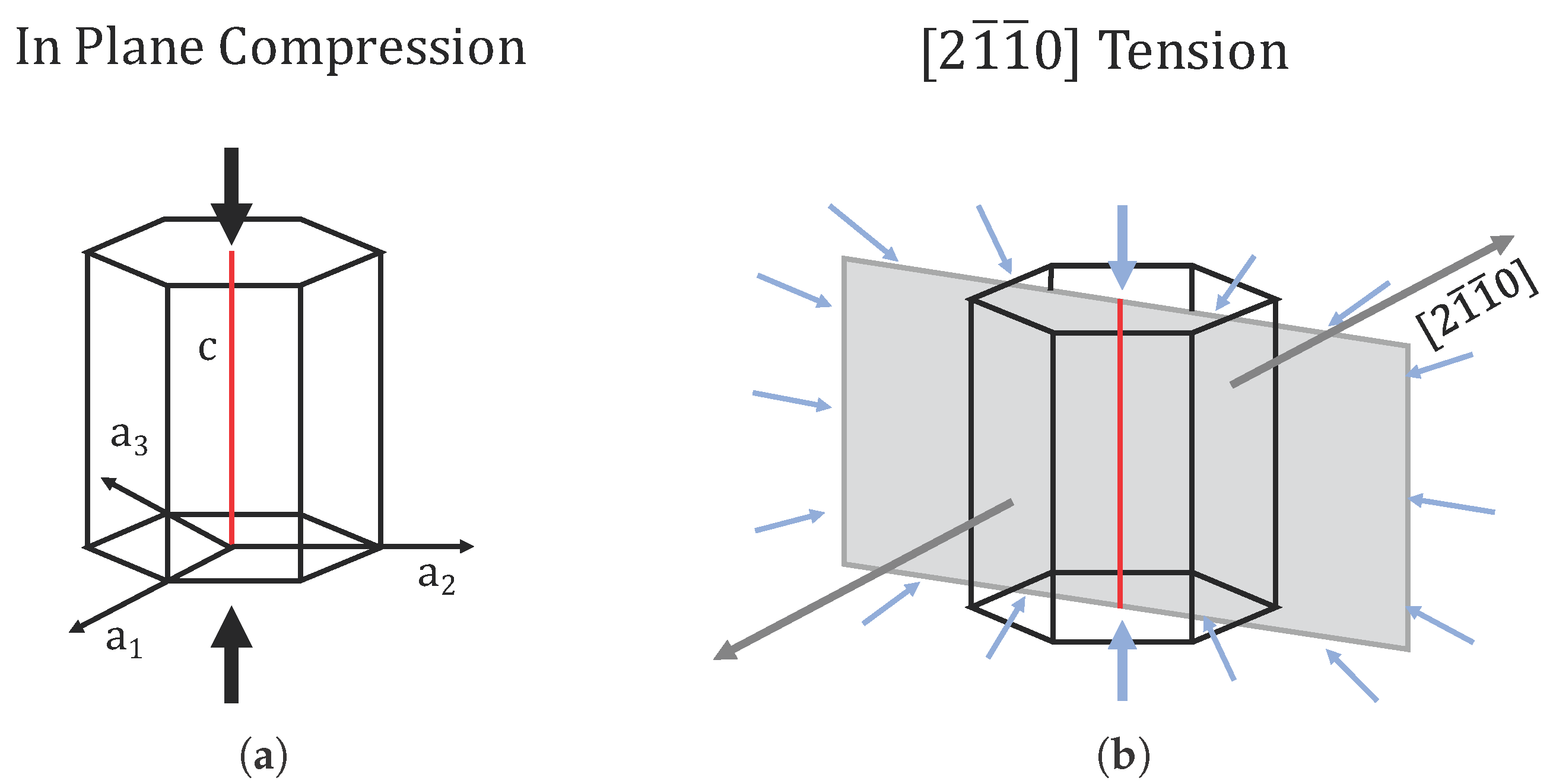
{1 0 1 1} twins nucleate under 〈c〉-axis contraction at much lower CRSS values than those previously reported in the literature under 〈c〉-axis compression. This behavior was attributed to the greater hydrostatic pressure in the case of contraction compared to the case of uniaxial 〈c〉 compression, which may assist the complex shuffles required for this twinning mode.

Author Contributions

Conceptualization, W.D.R., N.R.B. and H.E.K.; investigation, W.D.R. and N.R.B.; methodology, W.D.R., N.R.B., R.D.M. and Z.B.M.; project administration, R.D.M. and Z.B.M.; resources, H.R. and S.C.V.; supervision, W.R.W., H.R. and H.E.K.; validation, Y.P., C.D.B., A.L.O., W.R.W. and H.E.K.; writing—original draft, W.D.R., Y.P. and A.L.O.; writing—review and editing, Y.P., C.D.B., A.L.O., S.M., B.P., S.C.V. and H.E.K. All authors have read and agreed to the published version of the manuscript.

Funding

The research described and the resulting data presented herein, unless otherwise noted, were funded under PE 0602784A, Project T53 “Military Engineering Applied Research”, Topic 3 under Contract W56HZV-17-C-0095, managed by the US Army Engineer Research and Development Center. The work described in this document was conducted in the Center for Advanced Vehicular Systems at Mississippi State University. OPSEC permission was granted to publish this information.

Conflicts of Interest

The authors declare no conflict of interest. The funders had no role in the design of the study; in the collection, analyses, or interpretation of data; in the writing of the manuscript, or in the decision to publish the results.

References

  1. Pollock, T.M. Weight loss with magnesium alloys. Science 2010, 328, 986–987. [Google Scholar] [CrossRef] [PubMed]
  2. Mordike, B.L.; Ebert, T. Magnesium: Properties–applications–potential. Mater. Sci. Eng. A 2001, 302, 37–45. [Google Scholar] [CrossRef]
  3. Al-Samman, T.; Gottstein, G. Room temperature formability of a magnesium AZ31 alloy: Examining the role of texture on the deformation mechanisms. Mater. Sci. Eng. A 2008, 488, 406–414. [Google Scholar] [CrossRef]
  4. Zhang, Y.; Millett, P.C.; Tonks, M.; Biner, B. Deformation-twin-induced grain boundary failure. Scr. Mater. 2012, 66, 117–120. [Google Scholar] [CrossRef]
  5. Barnett, M.R. Twinning and the ductility of magnesium alloys: Part II.“Contraction” twins. Mater. Sci. Eng. A 2007, 464, 8–16. [Google Scholar] [CrossRef]
  6. Pratt, P.L.; Pugh, S.F. Twin accommodation in zinc. J. Inst. Met. 1952, 80, 653–658. [Google Scholar]
  7. Christian, J.W.; Mahajan, S. Deformation twinning. Prog. Mater. Sci. 1995, 39, 1–157. [Google Scholar] [CrossRef]
  8. Kumar, M.A.; Beyerlein, I.J. Local microstructure and micromechanical stress evolution during deformation twinning in hexagonal polycrystals. J. Mater. Res. 2020, 35, 217–241. [Google Scholar] [CrossRef]
  9. Baird, J.C.; Li, B.; Parast, S.Y.; Horstemeyer, S.J.; Hector, L.G., Jr.; Wang, P.T.; Horstemeyer, M.F. Localized twin bands in sheet bending of a magnesium alloy. Scr. Mater. 2012, 67, 471–474. [Google Scholar] [CrossRef]
  10. Paudel, Y.; Barrett, C.D.; Tschopp, M.A.; Inal, K.; El Kadiri, H. Beyond initial twin nucleation in hcp metals: Micromechanical formulation for determining twin spacing during deformation. Acta Mater. 2017, 133, 134–146. [Google Scholar] [CrossRef]
  11. Paudel, Y.; Indeck, J.; Hazeli, K.; Priddy, M.W.; Inal, K.; Rhee, H.; Barrett, C.D.; Whittington, W.R.; Limmer, K.R.; El Kadiri, H. Characterization and modeling of {1 0 1 2} twin banding in magnesium. Acta Mater. 2020, 183, 438–451. [Google Scholar] [CrossRef]
  12. Gilman, J.J. Mechanism of ortho kink-band formation in compressed zinc monocrystals. JOM 1954, 6, 621–629. [Google Scholar] [CrossRef]
  13. Rosenbaum, H.S. Non-basal slip and twin accommodation in zinc crystals. Acta Metall. 1961, 9, 742–748. [Google Scholar] [CrossRef]
  14. Rosenbaum, H.S. Nonbasal Slip in h.c.p. Metals and its Relation to Mechanical Twinning. In Deformation Twinning; Reed-Hill, R.E., Hirth, J.P., Rogers, H.C., Eds.; Grodon and Breach Science Publishers: New York, NY, USA, 1964; pp. 43–76. [Google Scholar]
  15. Rose, G. Über die im kalkspath vorkommenden hohlen canäle. Aus Den Abh. Königlichen Akad. Wissenschalten 1868, 23, 57–79. [Google Scholar]
  16. Priestner, R. The Relationship Between Brittle Cleavage and Deformation Twinning in BCC Metals. In Deformation Twinning; Reed-Hill, R.E., Hirth, J.P., Rogers, H.C., Eds.; Grodon and Breach Science Publishers: New York, NY, USA, 1964; pp. 321–355. [Google Scholar]
  17. Sleeswyk, A.W. Emissary dislocations: Theory and experiments on the propagation of deformation twins in α-iron. Acta Metall. 1962, 10, 705–725. [Google Scholar] [CrossRef]
  18. Sleeswyk, A.W. Twinning and the origin of cleavage nuclei in α-iron. Acta Metall. 1962, 10, 803–812. [Google Scholar] [CrossRef]
  19. Sleeswyk, A.W. 1/2〈1 1 1〉 screw dislocations and the nucleation of {112}〈1 1 1〉 twins in the bcc lattice. Philos. Mag. 1963, 8, 1467–1486. [Google Scholar]
  20. Barnett, M.R.; Stanford, N.; Cizek, P.; Beer, A.; Xuebin, Z.; Keshavarz, Z. Deformation mechanisms in Mg alloys and the challenge of extending room-temperature plasticity. JOM 2009, 61, 19–24. [Google Scholar] [CrossRef]
  21. Holden, J. Plastic deformation features on cleavage surfaces of metal crystals. Philos. Mag. 1952, 43, 976–984. [Google Scholar] [CrossRef]
  22. Zerilli, F.J.; Armstrong, R.W. Constitutive relations for the plastic deformation of metals. AIP conference proceedings. Am. Inst. Phys. 1994, 309, 989–992. [Google Scholar]
  23. Zerilli, F.J.; Armstrong, R.W. Dislocation mechanics based analysis of material dynamics behavior: Enhanced ductility, deformation twinning, shock deformation, shear instability, dynamic recovery. J. Phys. IV 1997, 7, 637–642. [Google Scholar] [CrossRef]
  24. Remy, L. Twin-slip interaction in fcc crystals. Acta Metall. 1977, 25, 711–714. [Google Scholar] [CrossRef]
  25. Remy, L. The interaction between slip and twinning systems and the influence of twinning on the mechanical behavior of fcc metals and alloys. Metall. Trans. A 1981, 12, 387–408. [Google Scholar] [CrossRef]
  26. Ma, Q.; El Kadiri, H.; Oppedal, A.L.; Baird, J.C.; Horstemeyer, M.F.; Cherkaoui, M. Twinning and double twinning upon compression of prismatic textures in an AM30 magnesium alloy. Scr. Mater. 2011, 64, 813–816. [Google Scholar] [CrossRef]
  27. Ma, Q.; El Kadiri, H.; Oppedal, A.L.; Baird, J.C.; Li, B.; Horstemeyer, M.F.; Vogel, S.C. Twinning effects in a rod-textured AM30 magnesium alloy. Int. J. Plast. 2012, 29, 60–76. [Google Scholar] [CrossRef]
  28. Barnett, M.R. Twinning and the ductility of magnesium alloys: Part I: “Tension” twins. Mater. Sci. Eng. A 2007, 464, 1–7. [Google Scholar] [CrossRef]
  29. Oppedal, A.L.; El Kadiri, H.; Tomé, C.N.; Kaschner, G.C.; Vogel, S.C.; Baird, J.C.; Horstemeyer, M.F. Effect of dislocation transmutation on modeling hardening mechanisms by twinning in magnesium. Int. J. Plast. 2012, 30, 41–61. [Google Scholar] [CrossRef]
  30. Martin, É.; Capolungo, L.; Jiang, L.; Jonas, J.J. Variant selection during secondary twinning in Mg–3% Al. Acta Mater. 2010, 58, 3970–3983. [Google Scholar] [CrossRef]
  31. Jonas, J.J.; Mu, S.; Al-Samman, T.; Gottstein, G.; Jiang, L.; Martin, Ė. The role of strain accommodation during the variant selection of primary twins in magnesium. Acta Mater. 2011, 59, 2046–2056. [Google Scholar] [CrossRef]
  32. Mu, S.; Jonas, J.J.; Gottstein, G. Variant selection of primary, secondary and tertiary twins in a deformed Mg alloy. Acta Mater. 2012, 60, 2043–2053. [Google Scholar] [CrossRef]
  33. Paudel, Y. Micromechanics-Crystal Plasticity Links for Deformation Twinning. Ph.D. Thesis, Mississippi State University, Mississippi State, MS, USA, 2018. [Google Scholar]
  34. Paudel, Y.; Barrett, C.D.; El Kadiri, H. Full-Field Crystal Plasticity Modeling of {1 0 1 2} Twin Nucleation. In Magnesium Technology 2020; Jordon, J., Miller, V., Joshi, V., Neelameggham, N., Eds.; Springer: Cham, Switzerland, 2020; pp. 141–146. [Google Scholar]
  35. Cheng, J.; Ghosh, S. Crystal plasticity finite element modeling of discrete twin evolution in polycrystalline magnesium. J. Mech. Phys. Solids 2017, 99, 512–538. [Google Scholar] [CrossRef] [Green Version]
  36. El Kadiri, H.; Baird, J.C.; Kapil, J.; Oppedal, A.L.; Cherkaoui, M.; Vogel, S.C. Flow asymmetry and nucleation stresses of {1 0 1 2} twinning and non-basal slip in magnesium. Int. J. Plast. 2013, 44, 111–120. [Google Scholar] [CrossRef]
  37. Wenk, H.R.; Lutterotti, L.; Vogel, S. Texture analysis with the new HIPPO TOF diffractometer. Nucl. Instrum. Meth. A 2003, 515, 575–588. [Google Scholar] [CrossRef]
  38. Takajo, S.; Vogel, S.C. Determination of pole figure coverage for texture measurements with neutron time-of-flight diffractometers. J. Appl. Crystallogr. 2018, 51, 895–900. [Google Scholar] [CrossRef]
  39. Losko, A.S.; Vogel, S.C.; Reiche, H.M.; Nakotte, H. A six-axis robotic sample changer for high-throughput neutron powder diffraction and texture measurements. J. Appl. Crystallogr. 2014, 47, 2109–2112. [Google Scholar] [CrossRef]
  40. Wenk, H.R.; Lutterotti, L.; Vogel, S.C. Rietveld texture analysis from TOF neutron diffraction data. Powder Diffr. 2010, 25, 283–296. [Google Scholar] [CrossRef] [Green Version]
  41. Hielscher, R.; Schaeben, H. A novel pole figure inversion method: Specification of the MTEX algorithm. J. Appl. Crystallogr. 2008, 41, 1024–1037. [Google Scholar] [CrossRef]
  42. Barrett, C.D.; El Kadiri, H.; Tschopp, M.A. Breakdown of the Schmid law in homogeneous and heterogeneous nucleation events of slip and twinning in magnesium. J. Mech. Phys. Solids 2012, 60, 2084–2099. [Google Scholar] [CrossRef]
  43. Barrett, C.D.; El Kadiri, H. The roles of grain boundary dislocations and disclinations in the nucleation of {1 0 1 2} twinning. Acta Mater. 2014, 63, 1–15. [Google Scholar] [CrossRef]
  44. El Kadiri, H.; Barrett, C.D.; Wang, J.; Tomé, C.N. Why are {1 0 1 2} twins profuse in magnesium? Acta Mater. 2015, 85, 354–361. [Google Scholar] [CrossRef] [Green Version]
  45. Barrett, C.D.; El Kadiri, H. Impact of deformation faceting on {1 0 1 2}, {1 0 1 1} and {1 0 1 3} embryonic twin nucleation in hexagonal close-packed metals. Acta Mater. 2014, 70, 137–161. [Google Scholar] [CrossRef]
  46. Barrett, C.D.; Tschopp, M.A.; El Kadiri, H. Automated analysis of twins in hexagonal close-packed metals using molecular dynamics. Scr. Mater. 2012, 66, 666–669. [Google Scholar] [CrossRef]
  47. El Kadiri, H.; Oppedal, A.L. A crystal plasticity theory for latent hardening by glide twinning through dislocation transmutation and twin accommodation effects. J. Mech. Phys. Solids 2010, 58, 613–624. [Google Scholar] [CrossRef]
  48. Partridge, P.G. Effect of cyclic stresses on the microstructures of hexagonal close packed metals. Czech. J. Phys. Sect. B 1969, 19, 323–332. [Google Scholar] [CrossRef]
  49. Molodov, K.D.; Al-Samman, T.; Molodov, D.A. Profuse slip transmission across twin boundaries in magnesium. Acta Mater. 2017, 124, 397–409. [Google Scholar] [CrossRef]
  50. Wang, F.; Barrett, C.D.; McCabe, R.J.; El Kadiri, H.; Capolungo, L.; Agnew, S.R. Dislocation induced twin growth and formation of basal stacking faults in {1 0 1 2} twins in pure Mg. Acta Mater. 2019, 165, 471–485. [Google Scholar] [CrossRef]
  51. Mahajan, S. Twin-slip and twin-twin interactions in Mo-35 at.% Re alloy. Philos. Mag. 1971, 23, 781–794. [Google Scholar] [CrossRef]
  52. Mahajan, S.; Chin, G.Y. Twin-slip, twin-twin and slip-twin interactions in Co-8 wt.% Fe alloy single crystals. Acta Metall. 1973, 21, 173–179. [Google Scholar] [CrossRef]
  53. Mahajan, S.; Chin, G.Y. Formation of deformation twins in fcc crystals. Acta Metall. 1973, 21, 1353–1363. [Google Scholar] [CrossRef]
  54. Sleeswyk, A.W.; Verbraak, C.A. Incorporation of slip dislocations in mechanical twins–I. Acta Metall. 1961, 9, 917–927. [Google Scholar] [CrossRef]
  55. Beyerlein, I.J.; Tomé, C.N. A dislocation-based constitutive law for pure Zr including temperature effects. Int. J. Plast. 2008, 24, 867–895. [Google Scholar] [CrossRef]
  56. Reed-Hill, R.E. Twin intersections & Cahns continuity conditions. Trans. Met. Soc. AIME 1964, 230, 809. [Google Scholar]
  57. Reed-Hill, R.E.; Robertson, W.D. The crystallographic characteristics of fracture in magnesium single crystals. Acta Metall. 1957, 5, 728–737. [Google Scholar] [CrossRef]
  58. Chin, G.Y. The role of preferred orientation in plastic deformation. In The Inhomogeneity of Plastic Deformation; Reed-Hill, R.E., Ed.; American Society for Metals: Russell, OH, USA, 1973; Chapter 4; pp. 83–112. [Google Scholar]
  59. Yu, Q.; Wang, J.; Jiang, Y.; McCabe, R.J.; Li, N.; Tomé, C.N. Twin–twin interactions in magnesium. Acta Mater. 2014, 77, 28–42. [Google Scholar] [CrossRef]
  60. Crocker, A.G. Double twinning. Philos. Mag. 1962, 7, 1901–1924. [Google Scholar] [CrossRef]
  61. Hartt, W.H.; Reed-Hill, R.E. Internal deformation and fracture of second-order {1 0 1 1}-{1 0 1 2}-twins in magnesium. Trans. Met. Soc. AIME 1968, 242, 1127–1133. [Google Scholar]
  62. Wonsiewicz, B.C. Plasticity of Magnesium Crystals. Ph.D. Thesis, Massachusetts Institute of Technology, Cambridge, MA, USA, 1966. [Google Scholar]
  63. Cizek, P.; Barnett, M.R. Characteristics of the contraction twins formed close to the fracture surface in Mg–3Al–1Zn alloy deformed in tension. Scr. Mater. 2008, 59, 959–962. [Google Scholar] [CrossRef]
  64. Koike, J. Enhanced deformation mechanisms by anisotropic plasticity in polycrystalline Mg alloys at room temperature. Metall. Mater. Trans. A 2005, 36, 1689–1696. [Google Scholar] [CrossRef]
  65. Koike, J.; Fujiyama, N.; Ando, D.; Sutou, Y. Roles of deformation twinning and dislocation slip in the fatigue failure mechanism of AZ31 Mg alloys. Scr. Mater. 2010, 63, 747–750. [Google Scholar] [CrossRef]
  66. Ando, D.; Koike, J.; Sutou, Y. The role of deformation twinning in the fracture behavior and mechanism of basal textured magnesium alloys. Mater. Sci. Eng. A 2014, 600, 145–152. [Google Scholar] [CrossRef]
  67. Ando, D.; Koike, J. Relationship between Deformation-Induced Surface Relief and Double Twinning in AZ31 Magnesium Alloy. J. Jpn. Inst. Met. 2007, 71, 684–687. [Google Scholar] [CrossRef]
  68. Hazeli, K.; Cuadra, J.; Streller, F.; Barr, C.; Taheri, M.; Carpick, R.; Kontsos, A. Three-dimensional effects of twinning in magnesium alloys. Scr. Mater. 2015, 100, 9–12. [Google Scholar] [CrossRef] [Green Version]
  69. Kelley, E.W.; Hosford, W.F., Jr. Plane-strain compression of magnesium and magnesium alloy crystals. Trans. Met. Soc. AIME 1968, 242, 5–13. [Google Scholar]
  70. El Kadiri, H.; Barrett, C.D.; Tschopp, M.A. The candidacy of shuffle and shear during compound twinning in hexagonal close-packed structures. Acta Mater. 2013, 61, 7646–7659. [Google Scholar] [CrossRef] [Green Version]
  71. Keshavarz, Z.; Barnett, M.R. EBSD analysis of deformation modes in Mg–3Al–1Zn. Scr. Mater. 2006, 55, 915–918. [Google Scholar] [CrossRef]
  72. Xu, S.W.; Kamado, S.; Matsumoto, N.; Honma, T.; Kojima, Y. Recrystallization mechanism of as-cast AZ91 magnesium alloy during hot compressive deformation. Mater. Sci. Eng. A 2009, 527, 52–60. [Google Scholar] [CrossRef]
  73. Barnett, M.R.; Keshavarz, Z.; Beer, A.G.; Ma, X. Non-Schmid behaviour during secondary twinning in a polycrystalline magnesium alloy. Acta Mater. 2008, 56, 5–15. [Google Scholar] [CrossRef]
  74. Beyerlein, I.J.; Wang, J.; Barnett, M.R.; Tomé, C.N. Double twinning mechanisms in magnesium alloys via dissociation of lattice dislocations. Proc. R. Soc. A Math. Phys. Eng. Sci. 2012, 468, 1496–1520. [Google Scholar] [CrossRef] [Green Version]
  75. Xu, D.S.; Chang, J.P.; Li, J.; Yang, R.; Li, D.; Yip, S. Dislocation slip or deformation twinning: Confining pressure makes a difference. Mater. Sci. Eng. A 2004, 387-389, 840–844. [Google Scholar] [CrossRef]
Figure 1. A schematic illustrating crack nucleation at the intersection of two twins, adapted from Priestner [16].
Metals 10 01403 g001
Figure 2. Twin–grain boundary (GB) interaction-induced regions of high stress (dark blue regions) leading to GB crack initiation in Mo according to molecular dynamics (MD) simulation by Zhang et al. [4] (with the permission of Elsevier, 2020). (Each pixelated dot represents an atom).
Metals 10 01403 g002
Figure 3. Magnesium AM30 crush rail is an extruded component used in an automotive shock absorption structure. This extrusion allows plane-strain conditions on the flat sections that promote a desirable double-fiber texture for studying twins as it promotes nucleation of multiple twin modes and variants in tension within neighboring grains.
Metals 10 01403 g003
Figure 4. [0 0 0 1] and 〈1 0 1 0〉 pole figures obtained from neutron diffraction analysis showing E T | | { 0 0 0 1 } plus E D | | { 0 0 0 1 } double fiber texture of an AM30 magnesium alloy. The extrusion direction (ED) is along the z-axis with the extrusion transverse direction (ET) along the x-axis and the extrusion normal direction (EN) along the y-axis. The pole figures show high concentrations of [1 0 1 0] oriented grains parallel to the extrusion direction [36] (with the permission of Elsevier, 2020).
Metals 10 01403 g004
Figure 5. Stress-strain relationship of AM30 alloy in extrusion and extrusion transverse (ET) directions. A sigmoidal curve for tension along the ET direction indicates high strain hardening, which is characteristic of profuse tension twinning, while tension along the extrusion direction (ED) alludes to deformation due to slip with minimal twinning [36] (with the permission of Elsevier, 2020).
Metals 10 01403 g005
Figure 6. (a) Inverse pole figure (IPF) map generated through electron backscatter diffraction (EBSD) scans showing initial microstructure of Mg AM30 before deformation and (b) the highlighted partitions of the areas of interests (AOI 1 and AOI 2) with discrete unit crystal orientations that are the focus of study.
Metals 10 01403 g006
Figure 7. (a) Micrographs depicting slip–twin interactions induced crack nucleation and (b) zoomed image showing crack opening due to slip-twin interactions from the dashed red region in (a).
Metals 10 01403 g007
Figure 8. (a) Twin–grain boundary (GB) interactions leading to crack nucleation due to a lack of strain accommodation. (b) Proper accommodation of strain is found at the surface where GB emerges through “kinking”. However, a crack is formed at the GB from interactions with another twin. Cracks are also noted from twin–twin interactions.
Metals 10 01403 g008
Figure 9. Micrographs of (a) {1 0 1 2} twin–twin interactions and (b) their involvement in crack nucleation viewed through zoomed image of the dashed red region in (a).
Metals 10 01403 g009
Figure 10. (a) Micrograph of evident contraction twins near long crack nucleation and (b) enlarged micrograph showing sharp surface steps made by these contraction twins.
Metals 10 01403 g010
Figure 11. (a) Crack formation due to contraction twin interactions and (b) EBSD micrograph showing the contraction twins with a misorientation of 56°.
Metals 10 01403 g011
Figure 12. Micrograph shows evidence of dual phase fracture. Cleavage and stepped terraces formed from twin interactions caused brittle failure, whereas the tormented regions show ductile failure.
Metals 10 01403 g012
Figure 13. Inverse pole figure maps at various incremental strains ranging from 0% to 5%. The tensile load is applied horizontally with respect to the image. The six variants of the {1 0 1 2} tensile twins nucleate and propagate in the parent grains resulting in a fully reoriented grain by 5% strain.
Metals 10 01403 g013
Figure 14. Twin variant selection in AOI 1. (a) The orientation map of the three evident twin pairs highlighted in green, yellow, and red. (b) By mapping the grain boundary occupancy of twins at 1% strain (just after nucleation), the perimeter fraction of twinning can be determined. The perimeter fraction shows a clear dominance of (1 0 1 2) twinning with evident dominate variants within the green and yellow pairs, i.e., (0 1 1 2) and (1 1 0 2) respectively. (c) The proposed variant pair twin planes are shown within parent orientation with their respective colors.
Metals 10 01403 g014
Figure 15. (a) Evolution of twin variant area fraction with strain for the three distinct pairs of the {1 0 1 2} system in AOI 1. (b) (0 0 0 1) pole figures showing the nucleation of three dominate twin variants forming at 1% strain then growing in intensity as the parent orientation diminishes.
Metals 10 01403 g015
Figure 16. Comparison of the stress states experienced by (a) in-plane compression and (b) [2 1 1 0] tension. The representation of [2 1 1 0] tension is simplified to a two-dimensional plane stress representing the plane of maximum compression in an attempt to visualize the complexity of the stress state experienced by contraction of the 〈c〉-axis due to the Poisson effect.
Metals 10 01403 g016
Figure 17. (a) Inverse pole maps revealing lattice reorientation due to profuse nucleation of {1 0 1 1} contraction twinning and slip as deformation proceeds from 0% to 5%. Although pyramidal slip 〈c + a〉 has a relatively higher SF, there is profuse nucleation of contraction twins. (b) The misorientation data of the twins indicates the presence of contraction twins as early as 2% strain with unit crystal orientation of both twins. The misorientation peak in the plot represents a twin boundary with parent grain.
Metals 10 01403 g017
Figure 18. Characterization of {1 0 1 1} contraction twins at (a) 4% strain revealing continuous nucleation of new twin variants. The twins were individually selected to be partitioned from the parent grain. The texture of the partitioned twins is shown in part (b). Double twins are found among the partitioned twins. The idealized texture of {1 0 1 1} contraction twins is shown in part (c). Not all twin variants are present, but they are representatives of each twin pair. The contraction twin variants are characterized by their respective color pair highlighted in the parent grain (a), pole figures (b,c), and crystal lattice (d).
Metals 10 01403 g018
Figure 19. Characterization of double twinning at low stresses. The twin of interest is fully formed by 3% strain and does not show signs of double twinning. By 4% strain, the twin of interest begins to double twin at the middle. Misorientation analysis between the double twin and the contraction twin is compared to confirm the presence of contraction and double twins.
Metals 10 01403 g019
Table 1. Values of resolved shear stress and Schmid factors determined by [0 0 0 1] loading with applied stress at yield of ET-Tension in Figure 2.
Slip or Twin PlaneSchmid FactorResolved Shear Stress
(h k i l) [u v t w]SFRSS (MPa)
Tension Twin Variants(1 0 1 2) [1 0 1 1]0.49919.96
(1 0 1 2) [1 0 1 1]0.49919.96
(0 1 1 2) [0 1 1 1]0.49919.96
(0 1 1 2) [0 1 1 1]0.49919.96
(1 1 0 2) [1 1 0 1]0.49919.96
(1 1 0 2) [1 1 0 1]0.49919.96
Slip SystemsBasal 〈a0-
Pyramidal 〈a0-
Pyramidal 〈c + a0.40116.04
Table 2. Schmid factors of each of the three distinct {1 0 1 2} pairs with [1 0 1 3 0] loading.
Tensile Twin Pairs(0 1 1 2)(1 1 0 2)(1 0 1 2)
Schmid Factor (m)0.2190.4790.245
Table 3. Values of resolved shear stress and Schmid factors determined by [2 1 1 0] loading with applied stress at 2% strain of ET-Tension in Figure 5.
Slip or Twin PlaneSchmid FactorResolved Shear Stress
(h k i l) [u v t w]SFRSS (MPa)
Comp. Twin Variants(1 0 1 1) [1 0 1 2]−0.31121.77
(1 0 1 1) [1 0 1 2]−0.31121.77
(0 1 1 1) [0 1 1 2]0-
(0 1 1 1) [0 1 1 2]0-
(1 1 0 1) [1 1 0 2]−0.31121.77
(1 1 0 1) [1 1 0 2]−0.31121.77
Slip SystemsBasal 〈a0-
Prismatic 〈a0.43330.31
Pyramidal 〈a0.38226.74
Pyramidal 〈c + a0.44631.22
Publisher’s Note: MDPI stays neutral with regard to jurisdictional claims in published maps and institutional affiliations.

