Article

Shear Strength and Aging Characteristics of Sn-3.0Ag-0.5Cu/Cu Solder Joint Reinforced with ZrO2 Nanoparticles

Department of Materials Science and Engineering, University of Seoul, 163 Seoulsiripdae-ro, Dongdaemun-gu, Seoul 02504, Korea
*
Author to whom correspondence should be addressed.
Metals 2020, 10(10), 1295; https://doi.org/10.3390/met10101295
Submission received: 2 September 2020 / Revised: 24 September 2020 / Accepted: 27 September 2020 / Published: 28 September 2020

Abstract

:
This study investigates the shear strength and aging characteristics of Sn-3.0Ag-0.5Cu (SAC 305)/Cu joints by the addition of ZrO2 nanoparticles (NPs) having two different particle size: 5–15 nm (ZrO2A) and 70–90 nm (ZrO2B). Nanocomposite pastes were fabricated by mechanically mixing ZrO2 NPs and the solder paste. ZrO2 NPs decreased the β-Sn grain size and Ag3Sn intermetallic compound (IMC) in the matrix and reduced the Cu6Sn5 IMC thickness at the interface of lap shear SAC 305/Cu joints. The effect is pronounced for ZrO2A NPs added solder joint. The solder joints were isothermally aged at 175 °C for 24, 48, 144 and 256 h. NPs decreased the diffusion coefficient from 1.74 × 10⁻¹⁶ m/s to 3.83 × 10⁻¹⁷ m/s and 4.99 × 10⁻¹⁷ m/s for ZrO2A and ZrO2B NPs added SAC 305/Cu joints respectively. The shear strength of the solder joints decreased with the aging time due to an increase in the thickness of interfacial IMC and coarsening of Ag3Sn in the solder. However, higher shear strength exhibited by SAC 305-ZrO2A/Cu joints was attributed to the fine Ag3Sn IMC’s dispersed in the solder matrix. Fracture analysis of SAC 305-ZrO2A/Cu joints displayed mixed solder/IMC mode upon 256 h of aging.

Graphical Abstract

1. Introduction

In the expanding information era, research has largely contributed to the development of high performance integrated circuit (IC). Meanwhile, the integration of the IC chips and their long term reliability remains a barrier in preventing the electronic industries to achieve their maximum efficiency [1]. Although many innovative joining techniques have been evolved, soldering is an essential joining step followed in the advanced IC packaging types such as through-hole technology, flip-chip and ball grid arrays [2]. Sn-Ag-Cu, Sn-Bi, Sn-In, Sn-Cu and Au-Sn are some of the potential lead-free solders used in the microelectronic packaging [3]. Among these Sn-3 wt.% Ag-0.5 wt.% Cu (SAC 305) solder is the primary candidate because their moderate melting temperature, good solderability, electrical performance, high-temperature resistance and mechanical properties such as strength and ductility [3,4]. The potential drawback in SAC 305 solder is the excessive growth of the Cu-Sn (Cu6Sn5 and Cu3Sn) inter-metallic compounds (IMC) at the solder/Cu interface due to the reactive wetting of Sn on copper substrate [4]. Alloying and nanoparticles (NPs) addition are the methods adopted in general to refine the IMC and to enhance the solderability and mechanical properties of SAC solder [3]. Presently, research in ceramic NPs reinforced SAC solder is given more attention owing to their stability in the solder matrix and the positive contribution in Ag3Sn IMC refinement, reliability as well as the suppression of the Cu6Sn5 IMC at the solder/Cu interface [3,4,5,6,7,8,9]. Tsao et al. and Chuang et al. observed an overall increase in mechanical properties such as yield strength, tensile strength and micro-hardness in the SAC 305 solder alloy after the addition of TiO2 and Al2O3 NPs [5,6]. Similar enhancement in mechanical properties are also reported by various authors for the addition of AlN [7], SnO2 [8] and ZrO2 [9] NPs in SAC solder by various authors.
However, the thickness of Cu6Sn5 and Cu3Sn IMCs formed at the interface of SAC solder and Cu substrate during manufacturing, repair and transportation decides the reliability of the solder joints [10]. With miniaturization, the reliability becomes the primary concern in fine pitch solder joints as the high current density and Joule heating drives the diffusion of Cu and Sn atoms along the interface [11]. Prolonged service time and elevated service temperature of the component results in a higher volume fraction of the brittle IMC at the interface, thus affecting the reliability of the fine-pitch solder joints [10,11]. By adding TiO2 NPs in SAC solder, Chang et al. [12] observed an overall reduction in the thickness of IMC from 4.44 μm to 2.78 μm due to the adsorption of nanoparticles at the SAC/Cu interface. Meanwhile, the addition of ZrO2 NPs also suppressed the IMC thickness and improved the joint strength of the SAC/Cu interface [9]. Aspalter et al. [13] reported that ZrO2, SiO2, TiO2 and Al2O3 NPs doped flux has decreased the Cu-Sn growth kinetics and enhanced the shear strength of solder/Cu joints. Gain et al. [14] reported that SAC/Cu with ZrO2 NPs has higher activation energy for total IMC formation which contribute to suppression effect as compared with monolithic SAC/Cu joints. Shang et al. [15] reported that Cu-Sn IMC suppression effect is more pronounced in small size TiO2 NPs having higher surface to volume ratio.
Although many investigations have proven the fact that NPs enhance the overall mechanical properties and slow down the growth Cu-Sn IMC growth at the interface, only NPs type and their addition level were considered during the materials design. However, at a constant addition level, the effect of nanoparticle size on the reliability and their aging characteristics has not been reported yet. ZrO2 NPs are chosen in the present work due to their effective surface active nature with good mechanical properties and chemical stability [9]. Among the various reliability testing methods, lap shear test resembles the real-life loading configuration experienced by the solder joints [8,16]. In the present study, lap shear test has been adopted to investigate the microstructure, Cu-Sn IMC growth and the shear strength of isothermally aged ZrO2 added SAC 305/Cu joints with regard to the NPs size.

2. Materials and Methods

2.1. Sample Preparation

Type 4 commercial SAC 305 solder paste of 99.99% purity (Alpha assembly solutions, Siheung-Si, South Korea) with RMA (Rosin Mildly Activated) flux was used as a base solder. ZrO2 NPs of 99.5% purity (Ditto Technology Co. Ltd., Gumpo-Si, South Korea) with an average particle size of 5–15 nm (hereafter referred as ZrO2A) and 70–90 nm (hereafter referred as ZrO2B) were used as additives to the base solder. Figure 1a and b shows field emission scanning electron microscope image of as-purchased spherical ZrO2A and ZrO2B NPs respectively. SAC 305-0.2 wt.% of ZrO2A and SAC 305-0.2 wt.% of ZrO2B nanocomposite solders (hereafter referred as SAC 305-ZrO2A and SAC 305-ZrO2B respectively) were prepared by mechanical mixing method. Accurately weighted ZrO2 NPs and the solder paste were mechanically mixed using a centrifugal mixer (THINKY, CA, USA) at 2000 RPM for 2 min. The sample was air cooled at an interval of 30 s to avoid the excessive heat generated during mixing.

2.2. Soldering and Microstructure Analysis

Copper plates (50 mm × 10 mm × 1 mm) were finely polished using SiC abrasive to make a uniform surface and to remove the surface contaminants. Flowingly, copper plates were soaked in 5 Vol.% HCl solution to get rid of the oxide layer and were ultrasonically cleaned with distilled water. Lap shear joints were fabricated as explained in Section 2.3. The joints were thermally aged in an oven at 175 °C for up to 256 h. For IMC analysis, the joints were mounted in epoxy, cross-sectioned and polished using standard metallographic techniques. Prior to scanning electron microscopy (SEM) analysis, the polished joints were etched in a solution containing 3 Vol.% HCl, 5 Vol.% HNO3 and 92 Vol.% CH3OH. The microstructure of the solder joint, IMC thickness and the fractured surfaces after shear test were analyzed using analytical scanning SEM (JEOL JSM-6010PLUS, Tokyo, Japan) attached with energy dispersive spectrometer (EDS). The average thickness of IMC at the interface was calculated from the ratio of the IMC area to its length calculated from SEM image. The β-Sn grain size, eutectic area percentage, Ag3Sn size and their inter-phase spacing were measured using Image-Pro Plus 6.0 program. Each data is an average value calculated from 20 high magnification images randomly chosen during SEM analysis.

2.3. Joint Strength Evaluation and Fractography

To prepare single lap shear joints, 200 μm thick nanocomposite solder paste was applied on the copper plates using a customized mask. Aluminum sheet having a thickness 150 μm was used as spacers to achieve uniformly thick solder joints during reflow since the joint clearance affects bond strength prominently. The specimens were clamped and reflowed at 25 °C for 90 s in a hot plate. After reflow, Al spacers were removed, extruded solder and flux residue at the edges were polished and cleaned with ethanol. Figure 2 schematically explains the fabrication of single lap shear test specimens. Shear test of the SAC 305/Cu joints was performed using AUTO-TENFORCE M/C (Korea-tech) tensile testing machine in room temperature at a fixed rate of 3.0 mm/min. For each condition, average value of the five samples were reported. The fractured surface was analyzed using SEM and EDS.

3. Results and Discussion

3.1. Effect of ZrO2 NPs Size on the Microstructure of SAC 305/Cu Shear Joints

Figure 3a–f shows the as-reflow microstructure of monolithic SAC 305/Cu and ZrO2 NPs added SAC 305/Cu joints. Figure 3a and b represents the microstructure of monolithic SAC 305/Cu joint and the corresponding high magnification image respectively. SAC 305 eutectic alloy upon solidification yields three phases: a needle-like Ag3Sn IMC phase (white contrast), an irregular polygon like Cu6Sn5 IMC phase (dark grey contrast) distributed within the dendritic β-Sn solid solution phase (light grey contrast) as shown in Figure 3 b. The average grain size of β-Sn is 21.1 ± 3.3 μm and the eutectic area is 16.6%. The average length and width of needle-like Ag3Sn phase are 4.9 ± 1.2 μm and 0.63 ± 0.08 μm respectively. The average spacing between the adjacent Ag3Sn phase in eutectic structure is 1.9 ± 0.6 μm.
As observed from Figure 3c–f, a significant refining is seen in the microstructure of as-reflowed SAC 305-ZrO2/Cu joints, most notably in SAC 305-ZrO2A/Cu joint. The area of Ag3Sn and β-Sn eutectic network has increased and the morphology of Ag3Sn IMC has been modified from needle-like to a near-spherical in ZrO2 added SAC 305/Cu joints. Also, the average grain size of β-Sn is decreased and the irregular polygon like Cu6Sn5 has been refined with the addition of ZrO2 nanoparticles as shown in Figure 3b,d. Table 1 enlists the average values of β-Sn grain size, eutectic area percentage, Ag3Sn size and their inter-phase spacing obtained from the addition of ZrO2 NPs in SAC 305/Cu joint. Each data is an average value calculated from 20 high magnification images randomly chosen during SEM analysis. From the table, it is clear that the refinement effect is higher in the microstructure of SAC 305-ZrO2A/Cu solder joint. When ZrO2B NPs are added, the β-Sn grain size and Ag3Sn IMC size are 11.3 ± 4.1 μm and 1.0 ± 0.5 μm respectively which is 46% and 62% reduction as compared with the monolithic SAC solder. Whereas the grain size reduction of β-Sn and Ag3Sn in ZrO2A added solder is 83% and 84% as compared with the monolithic SAC. These results reveal that at the constant addition level, smaller ZrO2 NPs had a significant influence in the refinement of SAC 305 solder.
Consistent with above results Tsao et al. [17] have reported that adding Al2O3 NPs has shown an overall refinement and increased eutectic network area in SAC 305 solders. Similarly, noticeable modification of eutectic Ag3Sn phase from needle-like to spherical-like has been observed for the addition of TiO2 NPs in SAC solder [5]. El-Daly et al. [18] has showed that addition of SiC nanoparticles in SAC 105 solder has resulted in a smaller β-Sn sub-grains. Effect of NPs in microstructural refinement in SAC solder has been studied by many researchers and explained qualitatively by the adsorption of surface-active material during the heterogeneous nucleation [17,18,19,20]. Upon melting, stable ZrO2 NPs remain dispersed in the molten solder. NPs are considered as surface active materials due to their high surface to volume ratio [19]. During solidification, the surface-active NPs are enriched along the phase boundaries and gets adsorbed on the growing plane, k. After the adsorption of surface-active material that is, ZrO2 NPs in this case, the surface free energy of the growing crystal plane k becomes [20]:
k γ c k A k = k γ 0 k A k R T k A k 0 c Γ k c d c ,
where c is the concentration of the surface-active material, γ c k and γ 0 k are the surface tension of the crystal plane k with and without the adsorption of surface-active NPs.   A k is the area of the plane k, Γ k the amount of surface-active NPs adsorbed at the plane k given by,
Γ k = c R T d γ k d c ,
where R and T are the molar gas constant and the absolute temperature respectively. In order to get the plane k to achieve a minimum surface free energy Equation (1) has to be minimum,
k γ 0 k A k R T k A k 0 c Γ k c d c min ,
where k γ 0 k A k term is independent of the concentration of surface-active material and hence assumed to be constant. Hence,
R T k A k 0 c Γ k c d c max .
For this condition to occur, the crystal plane with the maximum surface tension should grow faster and at the same time should adsorb maximum number of surface-active NPs. However, increase in adsorption of surface-active NPs tends to decrease the growth rate of the crystal plane k [19,20]. In Sn-Ag eutectic alloy, Ag3Sn is supposed to form during the onset of eutectic reaction wherein nucleating Ag3Sn crystal act as an epitaxial sink for the Ag and Sn atoms. Therefore, higher growth rate of Ag3Sn crystals in the eutectic melt which results in a needle-like morphology [9]. In ZrO2 NPs added solder, the dispersed nanoparticles in the eutectic melt gets adsorbed on the Ag3Sn IMC nucleating crystals thereby decreasing their growth rate resulting in near-spherical morphology.
Pronounced refining observed in the microstructure of SAC 305-ZrO2A/Cu joints as compared with the SAC 305-ZrO2B/Cu joints can be attributed to the higher surface to volume ratio of smaller NPs. Adsorption is a surface dominated phenomenon where a high surface to volume ratio of smaller ZrO2A NPs can enhance their adsorption effect on the growing plane of Ag3Sn. Moreover, at a constant addition level, the number of ZrO2A NPs will be more in the solder as compared to ZrO2B NPs. Therefore, the amount of ZrO2A NPs getting adsorbed on a growing Ag3Sn crystal plane k will be more and consequently shows a better refinement of β-Sn and Ag3Sn phases.

3.2. Effect of ZrO2 NPs Size on the Interfacial Cu6Sn5 Evolution in SAC 305/Cu Shear Joints

Figure 4a–c displays the Cu6Sn5 IMC formed at the interface of as-reflowed SAC 305/Cu, SAC 305-ZrO2A/Cu and SAC 305-ZrO2B/Cu joints respectively. The thickness of Cu6Sn5 IMC layer (grey contrast) at the interface of solder joints reduced with the addition of ZrO2 NPs. A scalloped Cu6Sn5 IMC with a thickness of 2.6 ± 0.9 μm and 1.7 ± 0.5 μm was observed at the interface of monolithic SAC 305/Cu and SAC 305-ZrO2A/Cu joint respectively. Furthermore, the width of the Cu6Sn5 scallop appears to be smaller in SAC 305-ZrO2A/Cu interface compared to that of monolithic SAC 305/Cu. On contrast, faceted Cu6Sn5 IMC with a thickness of 2.1 ± 0.7 μm was observed at the interface of SAC 305-ZrO2B/Cu joint. Scallop to faceted transition in Cu6Sn5 IMC has been previously reported for the addition of TiO2 and Al2O3 nanoparticles [15,17]. Thinner Cu6Sn5 IMC grains were formed at the Sn/Cu interface with the addition of 5 nm sized TiO2 NPs as compared to the 50 nm TiO2 NPs [17]. In consistent with previous reports, the suppression of Cu6Sn5 thickness at the interface is more noticeable for SAC 305 solder reinforced with smaller ZrO2A NPs.
Analogous to the refinement of Ag3Sn as explained in Section 3.1, Cu6Sn5 IMC suppression at the interface can also be explained with the theory of adsorption of surface-active material [21]. The propensity of adsorption (referred as equilibrium adsorption constant K0) for a surface-active NPs with different dimensions   K R A 0 and K R B 0 is given by [17],
K R A 0 K R B 0 = exp { 3 V m ( γ 0 k γ c k ) R ¯ T ( 1 R A 1 R B ) } ,
where   R A and   R B are the radius of A and B NPs.   V m is the molar volume for spherical nanoparticle, γ c k and γ 0 k are the surface tension of the Cu6Sn5 crystal plane k with and without the adsorption of NPs. γ 0 k γ c k term is negative as the adsorption of NPs decreases the surface tension of the growing Cu6Sn5 crystal plane k. Hence,
K R A 0 > K R B 0 .
Equation (6) signifies that smaller ZrO2A NPs can be easily adsorbed on the growing Cu6Sn5 crystal plane and decreases the surface tension of the Cu6Sn5 crystal plane k at a larger extent. This can be attributed to the higher surface to volume ratio. Further, for the fixed addition level more ZrO2A NPs gets adsorbed and contribute to higher suppression of the Cu6Sn5 growth as compared with ZrO2B NPs (Figure 4d).

3.3. Effect of ZrO2 NPs Size on the Cu6Sn5 aging Kinetics in SAC 305/Cu Shear Joints

Figure 5a–c displays the morphology and Cu-Sn IMC thickness of the monolithic SAC 305/Cu, SAC 305-ZrO2A/Cu and SAC 305-ZrO2B/Cu joints subjected to 175 °C isothermal aging for 24, 48, 144 and 256 h. As can be seen from Figure 5, overall Cu-Sn IMC thickness increases with aging time in the monolithic as well as ZrO2 reinforced SAC 305/Cu joints. However, increase in Cu-Sn IMC thickness appears to be more in monolithic SAC 305/Cu interface. Further, compared with the as-reflow condition, Cu6Sn5IMC morphology transformed from a scallop to planar type with aging. When Cu atoms diffuse towards the bulk solder, channels between the scallop shaped Cu6Sn5 provides a shorter diffusion path. Hence the growth rate is rapid at the channels resulting in planarization of Cu6Sn5 at the interface upon aging [22]. Besides that, Cu3Sn phase (dark grey contrast) having planar morphology emerges near to the Cu side in the monolithic as well as ZrO2 reinforced SAC305/Cu joints. With prolonged aging time (24 to 256 h), the overall thickness of IMC increases and Cu3Sn phase grows at an expense of Cu6Sn5. During aging, Cu6Sn5 phase transforms into Cu3Sn phase near to the Cu through the reaction (7) [10,23]:
C u 6 S n 5 + 9 C u 5 C u 3 S n .
The IMC growth kinetics at the solder/Cu interface can be expressed using an empirical power-law relationship [5,10,24]:
X = X 0 + D t ,
where X is the measured Cu-Sn IMC thickness and X0 is the initial Cu-Sn IMC thickness after the re-flow, D is the diffusion coefficient of the diffusing atoms which determines the growth rate, t is the aging time.
The value of D can be obtained from the linear regression analysis of X versus t1/2 plot [10]. Cu-Sn IMC thickness versus t and t1/2 plots are shown in Figure 6a and b respectively. As seen from Figure 6a, the thickness of Cu-Sn IMC increases with the aging time in all the SAC 305/Cu joints investigated here. Upon aging, Cu-Sn IMC growth appears to be higher for monolithic, followed by ZrO2B reinforced SAC solder. While, SAC 305-ZrO2A/Cu joints experienced slower Cu-Sn growth upon aging. With increasing aging time from 0 to 256 h, the IMC thickness increases from 2.6 ± 0.9 μm to 16.2 ± 0.3 μm, 1.7 ± 0.5 μm to 9.6 ± 0.8 μm and from 2.1 ± 0.7 μm to 10.2 ± 0.3 μm for monolithic SAC 305/Cu, SAC 305-ZrO2A/Cu and SAC 305-ZrO2B/Cu joints respectively. In all the joints, thickness of Cu-Sn IMC exhibited a parabolic relationship with the aging time signifying a diffusion-controlled growth as observed by Deng et al. [22]. The D values for SAC 305/Cu, SAC 305-ZrO2A/Cu and SAC 305-ZrO2A/Cu joints calculated from the Cu-Sn IMC thickness versus t1/2 plot as shown in Figure 6b are 1.74 × 10⁻¹⁶ m/s, 3.83 × 10⁻¹⁷ m/s and 4.99 × 10⁻¹⁷ m/s respectively. The D value for SAC 305/Cu joint in the present work is close to the D value (1.60 × 10⁻¹⁶ m/s) reported by Hu et al. [10] for SAC 305/Cu joints aged at 180 °C. Lower D values obtained for ZrO2 NPs reinforced SAC 305/Cu as compared to monolithic joint suggests that ZrO2 NPs have hindered the diffusion of Cu and Sn atoms during aging. Also, lower D value in SAC 305-ZrO2A/Cu joint as compared to SAC 305-ZrO2B/Cu joint shows smaller NPs have effectively controlled the Cu and Sn diffusion during aging.

3.4. Effect of ZrO2 Nanoparticle Size on the Shear Strength and Fracture Behavior of SAC 305/Cu Interface

Solder joints are often subjected to mechanical loading in actual service conditions, therefore to analyze and understand the ZrO2 NPs size on the reliability of the SAC 305/Cu joints, single lap shear tests have been carried out for ZrO2A and ZrO2B reinforced SAC 305/Cu joints. Figure 7 displays the shear strength of monolithic SAC 305/Cu, SAC 305-ZrO2A/Cu and SAC 305-ZrO2B/Cu solder joints in as-reflowed and in 175 °C isothermal aged condition. In general, deterioration in shear strength is noticed for all the solder joints with aging time. The average shear strength conducted on the as-reflowed monolithic SAC 305/Cu, SAC 305-ZrO2A/Cu and SAC 305-ZrO2B/Cu joints in as-reflowed condition are 35.9 ± 1.9 MPa, 39.7 ± 1.9 MPa and 38.9 ± 1.32 MPa respectively. In isothermal aging condition, ZrO2 NPs added SAC 305/Cu joints revealed higher shear strength as compared to the monolithic SAC 305/Cu. In particular, ZrO2A reinforced SAC 305/Cu joints exhibited better strength as compared to the ZrO2B reinforced SAC 305/Cu joints. After 144 h of isothermal aging, ZrO2A NPs reinforced SAC 305/Cu joints appear to retain the shear strength (35.4 ± 0.97 MPa) equivalent to the shear strength exhibited by the monolithic SAC 305/Cu joints in as-reflow condition.
Increase in shear strength for the solder joints has been reported for the addition of CoPd [25], ZrO2 [9], Al2O3 [26] and SiC [18] NPs. Higher shear strength in nanocomposite solder joints can be attributed to three factors: (a) presence of NPs and their dispersion strengthening, (b) finely dispersed Ag3Sn IMC particles in the solder matrix and (c) suppressed Cu6Sn5 IMC at the solder/Cu joint interface [27]. The presence of ZrO2 NPs and Ag3Sn IMC in solder strengthen the matrix by (a) generating geometrically necessary dislocations in the matrix in order to balance the co-efficient of expansion difference and elastic modulus difference between the matrix and the particle (ZrO2 NPs and Ag3Sn) and (b) obstructing the dislocation movement [5,27]. Additionally, refined Ag3Sn IMC in the matrix of ZrO2 added SAC 305 solder contribute to the strengthening through load-transferring mechanism. Good interface bonding between the dispersed particles and matrix contribute to a better load transferring ability [27]. The yield stress of the alloy due to the piling of dislocations upon load transfer depends on the spacing between the dispersed particles and is given by [17]:
τ 0 = G b τ π ν L ,
where G is the shear elastic modulus of the substrate; b is the Burgers vector; ν is the Poisson’s ratio; τ is the fracture stress of Ag3Sn particles and L is the average spacing between the Ag3Sn particles.
From Equation (9), smaller spacing between Ag3Sn IMC yields better load-transfer ability. In the present work, the average spacing between Ag3Sn IMC particles in the monolithic SAC 305 solder is 2.4 ± 0.7 μm. With the addition of ZrO2A and ZrO2B NPs, the average spacing between Ag3Sn particles reduce to 0.46 ± 0.06 μm and 1.1 ± 0.2 μm respectively (Table 1). According to Equation (9), the ratio of L S A C / L S A C Z r O 2 A for SAC 305-ZrO2A/Cu joint is 4.2, hence τ S A C Z r O 2 A / τ S A C = 2.0 . For SAC 305-ZrO2B/Cu joint, the ratio of L S A C / L S A C Z r O 2 B decreases to 2.6, hence τ S A C Z r O 2 B / τ S A C = 1.6 . The calculated yield stress by load transfer mechanism for SAC 305-ZrO2A/Cu joints is double than that of SAC 305-ZrO2B/Cu. In consistent with the theoretical Equation (9), higher shear strength observed for as-reflow SAC 305-ZrO2A/Cu joints can be attributed to the reduced Ag3Sn IMC spacing in the solder matrix.
Decrease in shear strength after aging can be related to two factors: (a) growth of Cu3Sn and Cu6Sn5 IMC’s at the interface and (b) coarsening of Ag3Sn IMC in the solder matrix [22,28]. As can be seen from the thickness plot (Figure 6a), the difference in the average Cu-Sn IMC thickness for the 256 h aged SAC 305-ZrO2A/Cu and SAC 305-ZrO2B/Cu joints is minor and hence cannot be considered as a significant factor for the difference in shear strength. Yang et al. [29] reported that thicker intermetallic layer corresponding to a higher reflow time does not decrease the shear strength as remarkably as thermal aging. It was reported that degradation in shear strength of aged SAC solder corresponds to the Ag3Sn IMC coarsening in the solder matrix rather than the growth of Cu-Sn IMC thickness at the interface [22]. However, thick IMC layer can be a potential source of cracks [22]. Coarsening of Ag3Sn IMC during thermal aging are controlled by Ostwald ripening where the smaller IMC dissolves in Sn-rich matrix, diffuse towards energetically favorable Ag3Sn and re-precipitate resulting in the growth of the Ag3Sn IMC size [30].
Figure 8a,b displays the microstructure of 48 h aged SAC 305-ZrO2A/Cu and SAC 305-ZrO2B/Cu joints respectively. The morphology of β-Sn grains were transformed from dendritic to equiaxed with definite grain boundaries. Figure 8c–f shows the magnified microstructure of ZrO2A and ZrO2B reinforced SAC 305/Cu joints after 48 and 256 h of aging. Ag3Sn IMC can be seen with light-grey contrast. Compared with the as-reflow condition (see Figure 3), Ag3Sn IMC coarsened and their fraction decreased upon 48 h of aging. This is consistent with dissolution and re-precipitation of Ag3Sn reported in the previous reports [30,31] Further, coarsening of Ag3Sn IMC appears to be higher for SAC 305-ZrO2B/Cu joint. ZrO2 A NPs dispersed in the solder matrix have contributed to a finer Ag3Sn re-precipitation upon aging and thereby responsible for their higher shear strength.
Figure 9 shows the top view of the fractured surface of as-reflowed and aged SAC 305-ZrO2A/Cu joints after the shear test. When tensile or shear tests are conducted on solder joints, fracture propagation mainly occurs in three general modes [22,32,33,34]. Mode 1—A typical ductile fracture where the cracks start at the solder/Cu joint and propagates within the solder. The fractured surface is completely covered with bulk solder. Mode 2—A ductile-brittle mixed fracture mode where the crack starts at the joint interface, initially propagates across the solder and then along the IMC. The surface fractured by mode 2 exhibits bulk solder as well as few exposed IMC. Mode 3—A brittle mode wherein the cracks begin and propagate along the IMC layer and fracture occurs completely in the interfacial IMC layer. The fractured surface with mode 3 failure shows only brittle IMC. From Figure 9a–d, it is clear that the as-reflowed and aged SAC 305-ZrO2A/Cu joints retained a ductile fracture mode in the solder region as evidenced from the plastic deformation and dimples along the shear direction. Dimples are formed as a result of coalescence of micro voids during plastic deformation [35]. As a consequence, solder surface tear along the shear direction resulting in tear ridges [34]. Also, in accordance with the earlier reports [36,37,38], the dimple size increases significantly with the aging time as seen in Figure 9b–d. With increased aging time of 256 h, although most locations of fractures surfaces are covered with solder, few Cu6Sn5 regions were exposed in some incidences as shown Figure 9d. Magnified image in Figure 9e shows the crack propagating along the Cu6Sn5 IMC beneath the solder. This indicates that fracture has occurred close to the solder/IMC interface. Upon shearing, solder/IMC interface experiences the maximum concentration of stress and becomes a preferred site for the onset of crack. Further, the combination of thick IMC along the interface and the lower fracture toughness of IMC (Cu6Sn5 and Cu3Sn) makes the interface a preferred location for the crack propagation [23]. Therefore, the localized shear occurring along the solder close to the IMC interface results in the fracture which agreed well with the previous reports [22,34].
Figure 10a–b shows the top view of the fractured surface and the crack propagation in 256 h aged SAC 305-ZrO2A/Cu and SAC 305-ZrO2B/Cu joints respectively. Apparently, crack propagation in the solder and interfacial IMC signifies a mixed fracture mode. Thicker Cu-Sn IMC after 256 h aging shares a weaker interface with the solder. Additionally, formation of Kirkendall voids (circled in Figure 10a,b) upon aging also degrades the fracture toughness of the IMC layer [39]. Clearly most of the locations in the fractured IMC region displayed a broken grain with a brittle cleavage plane. It was confirmed from the EDS analysis (Figure 10c) that the broken grains were Cu6Sn5. The exposed columnar grains adjacent to the Cu6Sn5 grains were identified as Cu3Sn from the EDS as shown in Figure 10d. This shows that intergranular fracture had occurred between the Cu6Sn5 and Cu3Sn grains in the IMC region and cleavage fracture has happened within the Cu6Sn5 grains.
In summary, the fracture occurred predominantly within the bulk solder for ZrO2 NPs reinforced SAC 305/Cu joints until 144 h of isothermal aging. However, the fracture surfaces of 256 h aged joints exhibited a mixed solder/IMC mode. Schematic illustrations of ductile and mixed fracture modes is shown in schematically in Figure 10e. The ductile to mixed transition at higher aging time can be attributed to coarsening of Ag3Sn precipitates, Kirkendall voids and increase in IMC thickness. Based on the observations, it can be interpreted that the higher shear strength displayed by SAC 305-ZrO2A/Cu joints after 256 h aging can be attributed to the presence of fine Ag3Sn IMC within the bulk solder. Therefore, bulk solder close to SAC 305-ZrO2A/Cu interface can experience higher shear stress as compared to SAC 305-ZrO2B/Cu.

4. Conclusions

The present work reports the microstructure, mechanical and IMC growth kinetics in aged SAC 305/Cu joints reinforced with two ZrO2 NPs having different particle sizes. A smaller ZrO2A NPs having an average particle size of 5–15 nm and relatively larger ZrO2B NPs having an average particle size of 70–90 nm and 0.2 wt.% of ZrO2 A and B nanocomposite solders were successfully prepared by a mechanical mixing method. Single lap shear joints were fabricated from the as-prepared ZrO2 nanocomposite solder paste and isothermally aged at 175 °C for 24, 48, 144 and 256 h. The conclusions are drawn as follows:
(1).
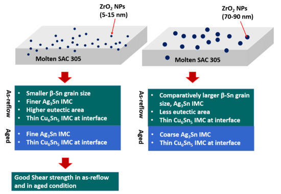
Microstructure of the as-reflow nanocomposite SAC 305-ZrO2/Cu joints exhibited higher eutectic area with refined β-Sn grain and Ag3Sn IMC as compared to the monolithic SAC 305/Cu joints. In particular, ZrO2 A NPs addition has contributed to a finer β-Sn and Ag3Sn grain size of 3.5 ± 2.0 μm and 0.41 ± 0.03 μm respectively with higher eutectic area as compared to the ZrO2B.
(2).
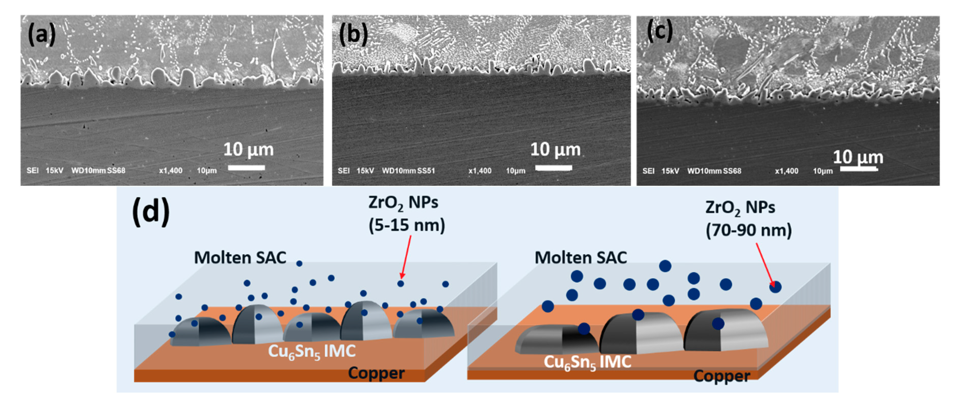
NPs in the SAC solder suppressed the thickness of Cu6Sn5 IMC at the interface from 2.6 ± 0.9 μm in monolithic to 1.7 ± 0.5 μm and 2.1 ± 0.7 μm for SAC 305-ZrO2A/Cu and SAC 305-ZrO2B/Cu joint respectively.
(3).
For all the investigated samples, IMC thickness increased linearly with the square root of aging time and the growth kinetics followed empirical-power law, indicating diffusion-controlled IMC growth. Addition of ZrO2 NPs decreased the diffusion coefficient remarkably. Notably, ZrO2A added SAC 305/Cu joint displayed the smallest diffusion co-efficient of 3.83 × 10⁻¹⁷ m/s. This is due to the presence of higher number of ZrO2 NPs effectively blocking the diffusion of Cu and Sn at the interface
(4).
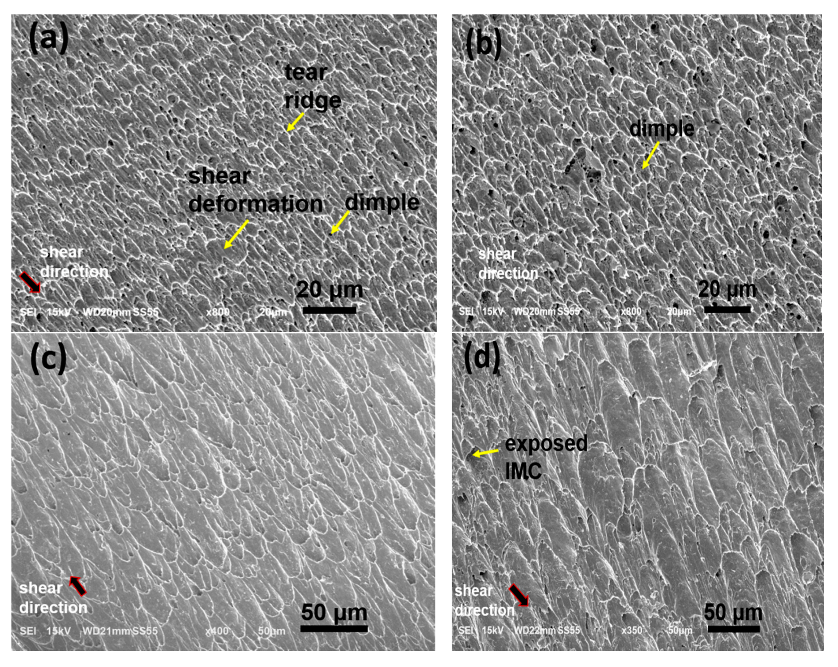
SAC 305-ZrO2A/Cu joints exhibited highest shear strength of 39.7 ± 1.9 MPa in the as-reflow condition owing to finer Ag3Sn IMC with reduced spacing as compared to SAC 305-ZrO2A/Cu joints. Generally, the shear strength of all joints decreased with the aging time. The decline in shear strengths upon aging can be related with the coarsening of Ag3Sn and the growth of Cu-Sn IMC at the interface. ZrO2A added SAC 305/Cu joint exhibited highest shear strength of after 256 h of aging due to the presence of fine Ag3Sn precipitates in the bulk solder.
(5).
Fracture analysis shows a ductile fracture mode for all the SAC 305-ZrO2A/Cu until 144 h of aging. After 256 h of aging, both SAC 305-ZrO2A/Cu and SAC 305-ZrO2B/Cu joints fractured by mixed fracture mode at the solder/IMC interface.
Therefore, to enhance the effectiveness of nanocomposite solders in the expanding electronic era, it is beneficial to consider nanoparticle size as a material design parameter along with nanoparticle type and addition level.

Author Contributions

Conceptualization, methodology, S.H.R.; formal analysis, writing—original draft preparation, S.H.R.; review and editing, J.P.J.; supervision, J.P.J.; analysis, project administration, S.J.H.; funding acquisition, J.P.J. All authors have read and agreed to the published version of the manuscript.

Funding

This work was supported by the Materials Parts Technology Development Program, (Project number: 20010580), Development of conductive nanomaterial technology for fine electrode junction of mini-LED, Funded by the Ministry of Trade, Industry & Energy (MI), Korea.

Conflicts of Interest

The authors declare no known financial and personal relationships that could have appeared to influence this work.

References

  1. Pu, L.; Liu, Y.; Yang, Y.; He, Q.; Zhou, Z.; Zhao, X.; Tan, C.; Tu, K.N. Effect of adding Ag to the medium entropy SnBiIn alloy on intermetallic compound formation. Mater. Lett. 2020, 272, 1–4. [Google Scholar] [CrossRef]
  2. Pu, L.; He, Q.; Yang, Y.; Zhao, X.; Hou, Z.; Tu, K.N.; Liu, Y. The microstructure and mechanical property of the high entropy alloy as a low temperature solder. In Proceedings of the 2019 IEEE 69th Electronic Components and Technology Conference, Las Vegas, NV, USA, 28–31 May 2019; pp. 1716–1721. [Google Scholar] [CrossRef]
  3. Kotadia, H.R.; Howes, P.D.; Mannan, S.H. A review: On the development of low melting temperature Pb-free solders. Microelectron. Reliab. 2014, 54, 1253–1273. [Google Scholar] [CrossRef]
  4. Jiang, N.; Zhang, L.; Liu, Z.; Sun, L.; Long, W.; He, P.; Xiong, M.; Zhao, M. Reliability issues of lead-free solder joints in electronic devices. Sci. Technol. Adv. Mat. 2019, 20, 876–901. [Google Scholar] [CrossRef] [PubMed] [Green Version]
  5. Tsao, L.C. Suppressing effect of 0.5 wt.% nano-TiO2 addition into Sn–3.5Ag–0.5Cu solder alloy on the intermetallic growth with Cu substrate during isothermal aging. J. Alloys Compds. 2011, 509, 8441–8448. [Google Scholar] [CrossRef]
  6. Chuang, T.H.; Wu, M.W.; Chang, S.Y.; Ping, S.F.; Tsao, L.C. Strengthening mechanism of nano-Al2O3 particles reinforced Sn3.5Ag0.5Cu lead-free solder. J. Mater. Sci. Mater. Electron. 2011, 22, 1021–1027. [Google Scholar] [CrossRef]
  7. Jung, D.H.; Sharma, A.; Lim, D.U.; Yun, J.H.; Jung, J.P. Effects of AlN Nanoparticles on the Microstructure, Solderability, and Mechanical Properties of Sn-Ag-Cu Solder. Metall. Mater. Trans. A 2017, 48, 4372–4384. [Google Scholar] [CrossRef]
  8. Babaghorbani, P.; Nai, S.M.L.; Gupta, M. Development of lead-free Sn-3.5Ag/SnO2 nanocomposite solders. J. Mater. Sci. Mater. Electron. 2008, 20, 571–576. [Google Scholar] [CrossRef]
  9. Shen, J.; Liu, Y.C.; Han, Y.J.; Tian, Y.M.; Gao, H.X. Strengthening effects of ZrO2 nanoparticles on the microstructure and microhardness of Sn-3.5Ag lead-free solder. J. Electron. Mater. 2006, 35, 1672–1679. [Google Scholar] [CrossRef]
  10. Hu, X.; Xu, T.; Keer, L.M.; Li, Y.; Jiang, X. Microstructure evolution and shear fracture behavior of aged Sn3Ag0. 5Cu/Cu solder joints. Mater. Sci. Eng. A 2016, 673, 167–177. [Google Scholar] [CrossRef]
  11. Huang, M.L.; Yang, F. Size effect model on kinetics of interfacial reaction between Sn-xAg-yCu solders and Cu substrate. Sci. Rep. 2015, 4, 7117. [Google Scholar] [CrossRef] [Green Version]
  12. Chang, S.Y.; Jain, C.C.; Chuang, T.H.; Feng, L.P.; Tsao, L.C. Effect of addition of TiO2 nanoparticles on the microstructure, microhardness and interfacial reactions of Sn3.5AgXCu solder. Mater. Des. 2011, 32, 4720–4727. [Google Scholar] [CrossRef]
  13. Aspalter, A.; Cerny, A.; Göschl, M.; Podsednik, M.; Khatibi, G.; Yakymovych, A.; Plevachuk, Y. Hybrid solder joints: Morphology and shear strength of Sn–3.0Ag–0.5Cu solder joints by adding ceramic nanoparticles through flux doping. Appl. Nanosci. 2020, 29, 1–7. [Google Scholar] [CrossRef]
  14. Gain, A.K.; Fouzder, T.; Chan, Y.C.; Yung, W.K.C. Microstructure kinetic analysis and hardness of Sn-Ag-Cu-1 wt% nano ZrO2 composite solder on OSP-Cu pads. J. Alloys Compds. 2011, 509, 3319–3325. [Google Scholar] [CrossRef]
  15. Shang, S.; Kunwar, A.; Yao, J.; Wang, Y.; Ma, H.; Wang, Y. Efect of the TiO2 Nanoparticles on the Growth Behavior of Intermetallics in Sn/Cu Solder Joints. Met. Mater. Int. 2019, 25, 499–507. [Google Scholar] [CrossRef]
  16. Sivasubramaniam, V.; Galli, M.; Cugnoni, J.; Janczak-Rusch, J.; Botsis, J. A Study of the Shear Response of a Lead-Free Composite Solder by Experimental and Homogenization Techniques. J. Electron. Mater. 2009, 38, 2122–2131. [Google Scholar] [CrossRef]
  17. Tsao, L.C.; Chang, S.Y.; Lee, C.I.; Sun, W.H.; Huang, C.H. effects of nano-Al2O3 additions on microstructure development and hardness of Sn3.5Ag0.5Cu solder. Mater. Des. 2010, 31, 4831–4835. [Google Scholar] [CrossRef]
  18. El-Daly, A.A.; Fawzy, A.; Mansour, S.F.; Younis, M.J. Thermal analysis and mechanical properties of An-1.0Ag-0.5Cu solder alloy after modification with SiC anao-sized particles. J. Mater. Sci. Mater. Electron. 2013, 24, 2976–2988. [Google Scholar] [CrossRef]
  19. Shen, J.; Chan, Y.C. Research advances in nano-composite solders. Microelectron. Reliab. 2009, 49, 223–234. [Google Scholar] [CrossRef]
  20. Xia, Z.; Chen, Z.; Shi, Y.; Mu, N.; Sun, N. Effect of Rare Earth Element Additions on the Microstructure and Mechanical Properties of Tin-Silver-Bismuth Solder. J. Electron. Mater. 2002, 31, 564–567. [Google Scholar] [CrossRef]
  21. Zhang, L.; Tu, K.N. Structure and properties of lead-free solders bearing micro and nano particles. Mater. Sci. Eng. R Rep. 2014, 82, 1–32. [Google Scholar] [CrossRef]
  22. Deng, X.; Sidhu, R.S.; Johnson, P.; Chawla, N. Influence of Reflow and Thermal Aging on the Shear Strength and Fracture Behavior of Sn-3.5Ag Solder/Cu Joints. Metall. Mater. Trans. A 2005, 36, 55–64. [Google Scholar] [CrossRef]
  23. Zuozhu, Y.; Sun, F.; Guo, M. Effect of Sn/Cu thickness ratio on the transformation law of Cu6Sn5 to Cu3Sn in Sn/Cu interface during aging. Mater. Res. 2018, 5, 086503. [Google Scholar] [CrossRef]
  24. Rizvi, M.J.; Chan, Y.C.; Bailey, C.; Lu, H.; Islam, M.N. Effect of adding 1wt% Bi into the Sn−2.8Ag−0.5Cu solder alloy on the intermetallic formations with Cu-substrate during soldering and isothermal aging. J. Alloys Compds. 2006, 407, 208–214. [Google Scholar] [CrossRef]
  25. Yakymovych, A.; Slabon, A.; Švec, P., Sr.; Plevachuk, Y.; Orovcik, L.; Bajana, O. Nanocomposite SAC solders: The effect of adding CoPd nanoparticles on the morphology and the shear strength of the Sn–3.0Ag–0.5Cu/Cu solder joints. Appl. Nanosci. 2020, 49. [Google Scholar] [CrossRef]
  26. Tsao, L.C.; Wu, R.W.; Cheng, T.H.; Fan, K.H.; Chen, R.S. Effects of nano-Al2O3 particles on microstructure and mechanical properties of Sn3.5Ag0.5Cu composite solder ball grid array joints on Sn/Cu pads. Mater. Des. 2013, 50, 774–781. [Google Scholar] [CrossRef]
  27. Nai, S.M.L.; Wei, J.; Gupta, M. Interfacial intermetallic growth and shear strength of lead-free composite solder joints. J. Alloys Compds. 2009, 473, 100–106. [Google Scholar] [CrossRef]
  28. Zhao, D.; Zhang, K.; Ma, N.; Li, S.; Yin, C.; Huo, F. Dynamic Observation of Interfacial IMC Evolution and Fracture Mechanism of Sn2.5Ag0.7Cu0.1RE/Cu Lead-Free Solder Joints during Isothermal Aging. Materials 2020, 13, 831. [Google Scholar] [CrossRef] [Green Version]
  29. Yang, W.; Felton, L.E.; Messler, R.W. The effect of soldering process variables on the microstructure and mechanical properties of eutectic Sn-Ag/Cu solder joints. J. Electron. Mater. 1995, 24, 1465–1472. [Google Scholar] [CrossRef]
  30. Tian, Y.; Ren, N.; Zhao, Z.; Wu, F.; Sitaraman, S.K. Ag3Sn compounds coarsening behaviors in Micro-joints. Materials 2018, 11, 2509. [Google Scholar] [CrossRef] [Green Version]
  31. Morando, C.; Fornaro, O.; Garbellini, O.; Palacio, H. Microstructure evolution during the aging at elevated temperature of Sn-Ag-Cu solder alloys. Procedia Mater. Sci. 2012, 1, 80–86. [Google Scholar] [CrossRef] [Green Version]
  32. Mahdavifard, M.H.; Sabri, M.F.M.; Said, S.M.; Rozali, S. High stability and aging resistance Sn-1Ag-0.5Cu solder alloy by Fe and Bi minor alloying. Microelectron. Eng. 2019, 208, 29–38. [Google Scholar] [CrossRef]
  33. An, T.; Qin, F. Effects of the intermetallic compound microstructure on the tensile behavior of Sn3.0Ag0.5Cu/Cu solder joint under various strain rates. Microelectron. Reliab. 2014, 54, 932–938. [Google Scholar] [CrossRef]
  34. An, T.; Qin, F. Intergranular cracking simulation of the intermetallic compound layer in solder joints. Comput. Mater. Sci. 2013, 79, 1–14. [Google Scholar] [CrossRef]
  35. Yao, P.; Li, X.; Han, X.; Xu, L. Shear strength and fracture mechanism for full Cu-Sn IMCs solder joints with different Cu3Sn proportion and joints with conventional interfacial structure in electronic packaging. Comput. Mater. Sci. 2019, 31, 6–19. [Google Scholar] [CrossRef]
  36. Yang, L.; Ge, J.; Zhang, Y.; Dai, J. Interfacial IMC layer and tensile properites of Ni-reinforced Cu/Sn-0.7Cu-0.05Ni/Cu solder joint: Effect of aging temerpature. Trans. Indian Inst. Metal. 2017, 70, 2429–2439. [Google Scholar] [CrossRef]
  37. Sujan, G.K.; Haseeb, A.S.M.A.; Nishikawa, H.; Amalina, M.A. Interfacial reaction, ball shear strength and fracture surface analysis of lead-free solder joints prepared using cobalt nanoparticle doped flux. J. Alloys Compds. 2017, 695, 981–990. [Google Scholar] [CrossRef]
  38. Lee, C.B.; Jung, S.B.; Shin, Y.E.; Shur, C.C. Effect of isothermal Aging on the ball shear strength in BGS joints with Sn-3.5Ag-0.75Cu solder. Mater. Trans. 2002, 43, 1858–1863. [Google Scholar] [CrossRef] [Green Version]
  39. Park, J.M.; Kim, S.H.; Jeong, M.H.; Park, Y.B. Effect of Cu–Sn intermetallic compound reactions on the Kirkendall void growth characteristics in Cu/Sn/Cu microbumps. Jpn. J. Appl. Phys. 2014, 53, 1–4. [Google Scholar] [CrossRef] [Green Version]
Figure 1. Field emission scanning electron microscopy image of as-received ZrO2NPs of varying size: (a) ZrO2A (5–15 nm) and (b) ZrO2B (70–90 nm) nanoparticles.
Metals 10 01295 g001
Figure 2. Schematic illustration for the fabrication of lap shear SAC 305/Cu joints.
Metals 10 01295 g002
Figure 3. Scanning electron microscope (SEM) micrograph of as-reflowed (a) SAC 305/Cu joint and (b) the corresponding microstructure, (c) SAC 305-ZrO2A/Cu joint and (d) the corresponding microstructure, (e) SAC 305-ZrO2B/Cu joint and (f) the corresponding microstructure.
Metals 10 01295 g003
Figure 4. SEM micrograph showing Cu6Sn5 IMC layer at the interface of as-reflowed (a) SAC 305/Cu joint, (b) SAC 305-ZrO2A/Cu joint, (c) SAC 305-ZrO2B/Cu joint and (d) Schematic illustration for the influence of smaller ZrO2A and larger ZrO2B NPs on the Cu6Sn5 IMC growth.
Metals 10 01295 g004
Figure 5. SEM micrograph of Cu-Sn IMC layer at the interface of the 175 °C isothermally aged (a) SAC 305/Cu, (b) SAC 305-ZrO2A/Cu and (c) SAC 305-ZrO2B/Cu joints for various aging time, A, B are the EDS analysis of points A, B in figure (a-4)
Metals 10 01295 g005
Figure 6. Plots of Total Cu-Sn IMC thickness versus (a) aging time and (b) square root of the aging time at 175 ℃ isothermal aging condition.
Metals 10 01295 g006
Figure 7. Shear strength of SAC 305/Cu, SAC 305-ZrO2A/Cu and SAC 305-ZrO2B/Cu joints in as-reflowed and in 175 °C isothermal aged condition.
Metals 10 01295 g007
Figure 8. (ad) SEM micrograph of 48 h isothermally aged joints. (a) SAC 305-ZrO2A/Cu joint and (c) the corresponding microstructure, (b) SAC 305-ZrO2B/Cu joint and (d) the corresponding microstructure. (e,f) microstructure of 256 h isothermally aged SAC 305-ZrO2A/Cu joint and SAC 305-ZrO2B/Cu joints respectively.
Metals 10 01295 g008
Figure 9. Fractured surfaces of (a) as-reflowed and (be) isothermally aged SAC 305-ZrO2A/Cu joint for various aging time: (b) 48 h, (c) 144 h, (d,e) 256 h, A, B are the EDS analysis corresponding to the points A and B in figure (e).
Metals 10 01295 g009aMetals 10 01295 g009b
Figure 10. Solder/IMC fracture and crack propagation in 256 h isothermally aged (a) SAC 305-ZrO2A/Cu joint, (b) SAC 305-ZrO2B/Cu joint, (c,d) EDS analysis corresponding to points A and B in (b), (e) schematic illustration of the fracture modes.
Metals 10 01295 g010
Table 1. Average grain size, Ag3Sn spacing and eutectic area percentage for the as-reflow monolithic and ZrO2 reinforced SAC/Cu joint.
SampleAg3Sn (μm)Ag3Sn Spacing (μm)β-Sn Grain Size (μm)Eutectic Area %
LengthWidthGrain Size
SAC 3054.9 ± 1.20.63 ± 0.082.7 ± 0.62.4 ± 1.421.1 ± 3.316.6
SAC 305-ZrO2A0.45 ± 0.070.37 ± 0.030.41 ± 0.030.56 ± 0.083.5 ± 2.032.4
SAC 305-ZrO2B1.4 ± 1.10.71 ± 0.071.0 ± 0.50.89 ± 0.111.3 ± 4.126.9

