Article

Influence of Non-Parallelism on the Micro-Interface Lubrication Mechanism of Water-Lubricated Bearings

1
CNOOC EnerTech Equipment Technology Co., Ltd., Tianjin 300457, China
2
College of New Energy, China University of Petroleum (East China), Qingdao 266580, China
*
Author to whom correspondence should be addressed.
Lubricants 2024, 12(2), 49; https://doi.org/10.3390/lubricants12020049
Submission received: 6 December 2023 / Revised: 23 January 2024 / Accepted: 30 January 2024 / Published: 8 February 2024
(This article belongs to the Special Issue Water-Lubricated Bearings)

Abstract

:
Water-lubricated bearings can effectively solve the pollution problem caused by lubricant leakage and are used in offshore engineering equipment for this reason. Aiming at the problems of unclear and undefined micro-interface lubrication mechanisms of water-lubricated bearings, this paper investigates the influence of non-parallel micro-cavities on the micro-interface lubrication mechanism of bearings. Based on a single micro-cavity model, the lubrication mechanism of micro-cavities is studied in this paper. Lubrication models of the non-parallel contact friction pairs model are built, and the effect of the non-parallelism on the lubrication performance of the micro-cavities is obtained using the computational fluid dynamics method. The results show that, under the same Reynolds number and cavitation pressure, the wedge effect caused by the non-parallelism causes the pressure at the inlet to rise, thus increasing the load-carrying capacity. The existence of non-parallelism limits the rise of the high pressure of the inertia effect on the micro-cavities and reduces the load-carrying capacity. The presence of non-parallelism decreases the area of the negative pressure proportion and increases the proportion of the positive pressure zone inside the micro-cavities, thus increasing the load-carrying capacity.

1. Introduction

Water-lubricated bearings can effectively solve the pollution problem of lubricant leakage from marine equipment. In particular, the use of seawater as the lubricating medium can eliminate the harsh sealing system, simplify the positioning and propulsion system, and improve working reliability. In most cases, sliding bearings work in the mode of hydrodynamic lubrication. At the same time, the wear of the working surfaces of the bed and sleeve is negligibly small. However, in the period of start-up and stoppage, the deposits that in normal exploitation work under conditions of hydrodynamic lubrication switch to work under conditions of boundary lubrication. In these periods, the conditions of external friction and very intense wear and tear are realized. Wear is a process whose origin and development are essentially related to boundary lubrication conditions. As the influence of the surface morphology effect cannot be ignored, the water-lubricated bearing lubrication mechanism is no longer pure fluid dynamic pressure lubrication or elastic flow lubrication. Surface roughness will directly affect the entire bearing’s hydrodynamic characteristics, which in turn affect the bearing lubrication mechanism and lubrication performance. Aiming to solve the many problems within the micro-interface of water-lubricated bearings, both domestic and foreign scholars have carried out much research and made positive contributions. Wang et al. [1] established and investigated a hydrodynamic fluid-solid coupling model for water-lubricated polymer bearings with grooves, and explored the influence laws of factors such as the physical properties of the lining layer and the rotational speed on the surface characteristics. Zhang et al. [2] took biometric features into account in the design of surface structures from a biomimetic point of view and found that their surface structures were more helpful in increasing the load-carrying capacity and decreasing the friction force compared to geometric feature structures. Xie et al. [3,4] investigated the bearing micro-rough contact load ratio and lubrication state by modeling a water-lubricated bearing with micro-convex grooves, and further explored the relationship between the specific parameters and the contact ratio. Zhou et al. [5] processed circular grooves with different geometrical parameters on the surface of a titanium alloy by using a laser pitting technique and tested the friction characteristics of the titanium alloy on an experimental machine to analyze the effect of factors such as surface structural parameters on lubrication and tribological properties. In order to overcome the shortcomings of the traditional water-lubricated single-bushing bearings, Xie [6] proposed a novel double-liner bearing that enriched the lubrication theory system. Aiming to influence the misalignment effect on the performance of marine water-lubricated bearings, Xie [7] established a new lubrication model with a bidirectional misalignment effect, and the study proposed a new analysis method and provided important guidance for practical application. Surface texturing is the process of creating an array of pits or grooves with a specific size distribution on the friction surface by laser processing, ion etching, electro-deposition, abrasive flow jetting, etc. [8,9]. When relative motion is generated in a friction pair, the wedge effect of the pits generates additional hydrodynamic pressure between the oppositely moving surfaces, which improves the frictional properties of the lubricated contact surfaces. With advances in machining technology, surface texturing has been successfully applied to many products such as plain bearings, thrust bearings, mechanical face seals, cutting tools, piston rings, and disk storage devices. For example, Yang et al. [10] compared the tribological properties of surface textured and non-textured rubber samples under water lubrication, low speed, and overload conditions in order to control the wear of the propulsion-bearing rubber plate of an underwater vehicle, and the results showed that the frictional torque and coefficient of friction of the surface textured rubber samples were reduced by 15.5%, and the average hourly wear rate was reduced by 23.3%, which not only reduced friction but also improved the wear resistance. In 1966, Hamilton et al. [11] found for the first time that the irregular pits on the surface of rotary shaft end seals could generate additional fluid pressure and thus improve the surface load-carrying capacity. Anno et al. [12] further confirmed the lubrication improvement effect of end seals and thrust bearings.
After the discovery of the additional load-carrying property of surface texture, its cavitation effect attracted attention. In the dispersion zone of the texture unit, the pressure of the lubricant is lower than the gas saturation pressure or evaporation pressure, leading to the occurrence of cavitation. Hamilton et al. [11] observed the cavitation phenomenon at the pits through the transparent rotor test and proposed, for the first time, that the asymmetric pressure distribution caused by cavitation is the main reason for the texture load-carrying capacity. Qiu et al. [13,14] proposed a model for predicting the cavitation behavior in parallel textured friction pairs and found that the relative motion speed between the friction pairs has a significant effect on the cavitation phenomenon inside the texture. Zhang et al. [15] pointed out that the cavitation region changes with the number of textures and texture size, and when the operating conditions are stable, the morphology and the proportion of the cavitation region reach stability. Meng [16,17] found that the change in the area of the friction surface bubble induced by cavitation could increase the load-carrying capacity and decrease the surface friction, and that the change was affected by the distribution of the texture. Bai et al. [18] conducted an experimental study on the cavitation phenomenon in textured thrust bearings and found that the shape and area of the cavitation varied with the size of the texture. Li et al. [19] analyzed the loading mechanism of the texture and found that the non-isotropic superposition effect between the micro-dynamic pressure effect and the original dynamic pressure effect determines the loading capacity of the textured water-lubricated plain bearings. Fowell et al. [20] and Olver et al. [21], by investigating the tribological properties of textured bearings considering cavitation, suggested that the negative pressure in the cavitation region can draw more lubricant into the texture region, thus increasing the hydrodynamic pressure effect and load-carrying capacity. Dobrica et al. [22] found that cavitation has a great influence on the performance of parallel textured contact pairs by studying the effect of cavitation on the hydrodynamic properties of textured contact pairs. Wang et al. [23] found, through experimental studies, that under certain velocity and load conditions, surface texture induces cavitation in the lubricant and generates bubbles at the exit of the pits.
With the rapid development of techniques for solving the Navier-Stokes equations, the inertia effect of the texture was proposed by Arghir et al. [24]. By comparing the pressure generation effect inside the texture with different convective inertia, it is found that all the textures exhibit a net lift on the parallel wall as the convective inertia increases. Billy et al. [25] studied the influence of the inertia effect of lubricating medium on the load-carrying performance of the texture under high-speed conditions and found that with the enhancement of the texture inertia effect, the load-carrying capacity of the upper wall of the texture increased significantly. Sahlin et al. [26] carried out two-dimensional hydrodynamic analysis of a single texture and found that the load-carrying capacity of the texture is mainly caused by fluid inertia, and the load-carrying capacity of the texture increases with the increase in the Reynolds number. Feldman et al. [27] numerically analyzed the effect of the inertia effect in textured parallel surfaces and found that the inertia effect is negligible when the liquid film thickness is less than 3% of the texture diameter. Subsequently, Dobrica et al. [28,29] drew a completely opposite conclusion to the previous scholars and found that in general, the inertia had a negative effect and reduced the load-carrying capacity of the friction pair. For this reason, Cupillard et al. [30] stated that there is a special depth. Above this value, inertia negatively affects the load-carrying capacity, and below it, inertia positively affects the load-carrying capacity. These effects are amplified with an increasing Reynolds number for a given texture depth. Similar conclusions were obtained by Kraker et al. [31] and Syed et al. [32], who stated that the influence of inertial effects on the load-carrying capacity depends on the localized flow inside the texture. Wang et al. [33] analyzed the local lubrication mechanisms of textures in journal bearings from a microflow perspective while considering the interactions between textures and film formation in the entirety of the bearing. Khalil et al. [34] carried out a theoretical analysis and showed that inertial forces combined with centrifugal forces increase the pressure of the friction pair. Woloszynski et al. [35] found that the inertia effect is enhanced with the increase in Reynolds number.
In addition to these two effects, other effects have been gradually discovered and proposed to better explain the load-carrying mechanism of the texture. Tonde et al. [36,37,38,39] proposed two principles for generating pressure within the texture: the textured region provides a “virtual step” at the inlet; and the textured region acts as a resistance factor for lubricant escape, increasing the amount of lubricant available in the high-pressure zone. Subsequently, Etsion and Halperin [39] proposed the “delayed rupture effect” of the texture on the liquid film. In addition, Olver and Fowell [21] proposed the “entrainment and inlet suction” effect of the lubricant medium inside the texture, that is, the sliding wall generates a lower pressure than the external atmospheric pressure near the inlet of the texture, allowing more lubricant to be sucked into the friction pair. In addition to these roles, the formation of the lubrication film during sliding plays an important role in the frictional behavior of surface textures. Different lubrication states play different roles in the formation of lubricant film. Xu et al. [40] investigated the effect of the formation of lubricant film on the tribological properties of elliptical texture surfaces under fluid lubrication and boundary lubrication, respectively, and found that the surface friction coefficients of the surfaces with and without texture are similar under fluid lubrication, which suggests that it is the lubricant film adsorbed on the surfaces that dominates the tribological behaviors of the surfaces under fluid lubrication, rather than the textures. The new Navier-Stokes model proposed by Rom and Müller [41] is based on the modification of the Reynolds equations and provides more accurate results than the Reynolds and Stokes equations, which can be applied to deep surface texture and high-speed flow. However, there is still room for improvement in the setting of the boundary conditions so that the theoretical model can also be investigated in more depth by applying a simplified method to the unit problem. Surface micro-textures represent an important trend in tailoring friction and/or wear. In the future, synergistic effects with lubricant rheology and other surface modification approaches will come increasingly into focus [42].
The current research on the lubrication mechanism of the micro interface is relatively scattered, and the systematic research on the load-bearing mechanism of the micro-interface water-lubricated bearing still needs further development. Most of the studies on the micro-interface lubrication mechanism are based on parallel friction pairs. However, in practical applications such as plain bearings, the relative motion of the non-parallel surface is more common. Therefore, by establishing a non-parallel contact pair geometric model, computational fluid dynamics is used to calculate the inertia effect, cavitation effect, and inlet wedge effect at different degrees of parallelism and to analyze the effect of non-parallelism on the lubrication performance of the micro-cavities.
In summary, the current research on the micro-interfacial lubrication mechanism is relatively decentralized, and the systematic research on the micro-interfacial load-carrying mechanism still needs to be further developed. Most of the studies on the micro-interface lubrication mechanism are based on parallel friction pairs. However, in practical applications such as plain bearings, the relative motion of the non-parallel surface is more common. Therefore, to address the deficiencies in the studies of the above scholars, the analysis will focus on elaborating and explaining the influence of micro-cavities on the lubrication mechanism of the non-parallel micro interface. In this study, the influence of non-parallelism on the lubrication performance of microcavities is analyzed by establishing a geometrical model of non-parallel contact pairs and using computational fluid dynamics to calculate the inertia effect, cavitation effect, and inlet wedge effect under different parallelisms. This paper explores the change rule between non-parallelism and lubrication performance, grasps the evolution law of hydrodynamic properties with surface morphology, explains the inner mechanism of the law, and provides a theoretical basis for further development of optimization design of micro-interface morphology characteristics.

2. Numerical Methods

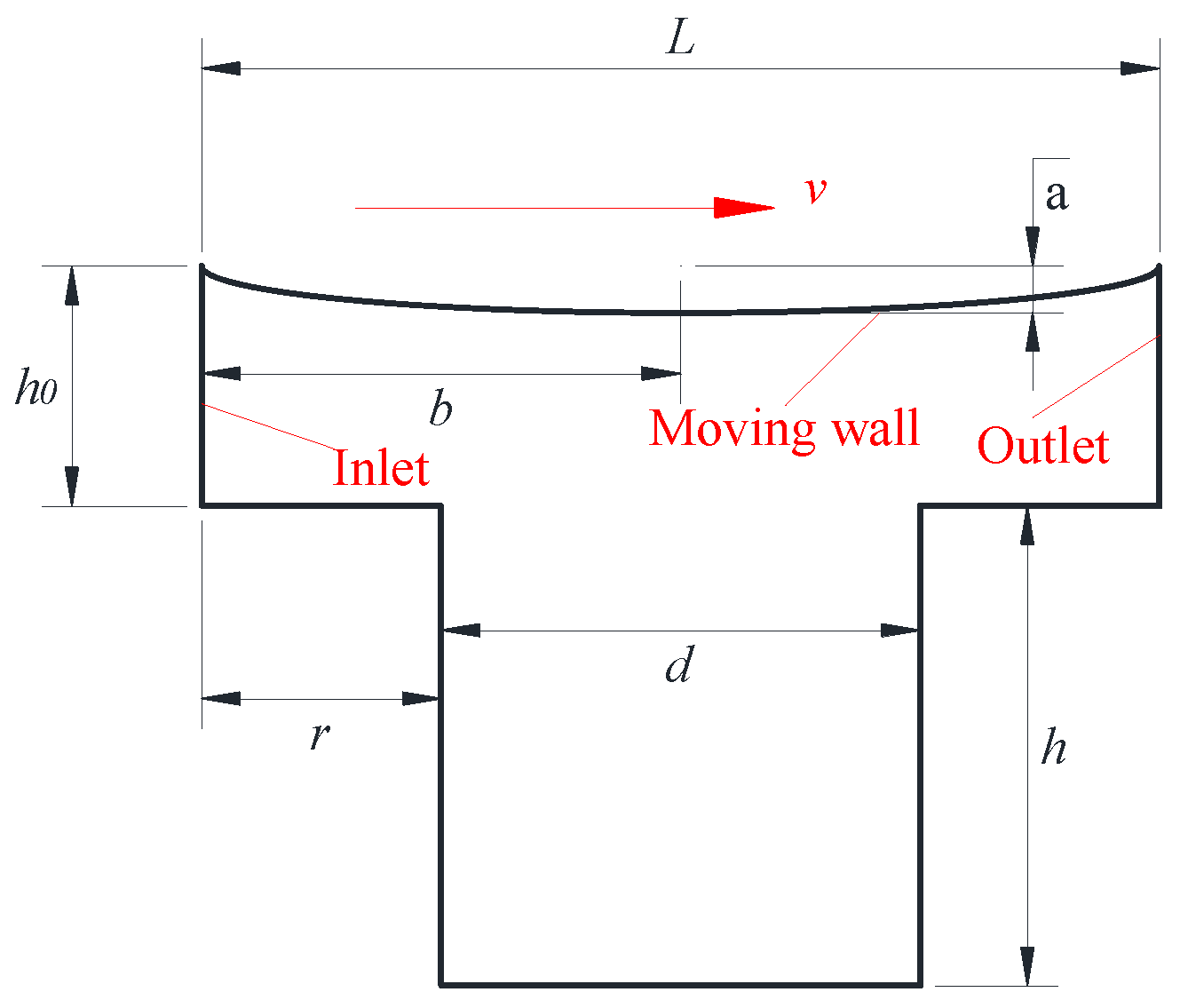
2.1. Physical Model and Boundary Conditions

The flow field inside the single micro-cavity is analyzed. The fluid distribution inside the micro-cavity is continuous. The N-S equation is satisfied. The following assumptions are used for convenience in the analysis and modeling:
(1)
The volumetric force effects are neglected.
(2)
The fluid inside the microcavity is incompressible, isobaric, and iso-viscous.
(3)
The model is a two-dimensional model with a symmetric distribution in the z-direction.
The schematic diagram of a single micro-cavity in this study is shown in Figure 1. The upper wall slides from left to right with velocity v (as indicated by the arrows in the Figure 1), while the no-slip boundary condition is used. The inlet and outlet are periodic boundary conditions and the rest of the walls are fixed boundary conditions. The parameters of lubrication medium parameters and boundary conditions used are listed in Table 1. The subscript l denotes the liquid phase, v denotes the vapor phase, and ope denotes the operating environment.
To determine the suitable mesh number, a mesh independent study is carried out. As a result, the baseline model has approximately 70,000 grid elements.

2.2. Governing Equation

In the present study, the lubricant is treated as an incompressible Newtonian fluid with a constant viscosity and density.
The degree of non-parallelism is denoted as θ, where θ = a/b. In the equation, a is the distance of the thinnest part of the liquid film of the micro-cavities from the upper surface of the parallel friction pair; b is the distance from the pressure inlet to the centerline of a single micro-cavity. The upper surface of the friction pair is formed by a section of the elliptical arc. Keeping the value of b constant, θ is taken as 0.005, 0.0075, and 0.01 to build computational models for comparison with the parallel micro-cavity friction pair (θ = 0). For the non-parallel contact pair models with different parallelisms, the lubricant film thickness equation is as follows:
H = h + h 0
where H is the total oil film thickness; h0 is the friction pair clearance; h is the depth of micro-cavity.
h 0 = { h 0 ( p a r a l l e l   c o n t a c t   p a i r ) h 0 a ( n o n p a r a l l e l   c o n t a c t   p a i r )
where a is the decrease in value caused by non-parallelism.
The basic flow-governing equations including the continuity equation and the momentum conservation equation are given as follows:
t ( ρ m ) + ( ρ m v m ) = 0
t ( ρ m v m ) + ( ρ m v m v m ) = [ μ m ( v m + v m T ) ] p + S v
v m = k = 1 n α k ρ k v k ρ m
ρ m = k = 1 n α k ρ k
where the ρm is the mixed phase density, vm is the mass average velocity, and αk is the volume fraction of phase k.
The “mixture” model is used to describe the multiphase flow of lubricant with cavitation. The Singhal [21] et al. “full cavitation model” can be used in the continuity equation and momentum equation of the mixture.
t ( ρ m f k ) + ( ρ m v m f k ) = ( μ m f k ) + R e R c
where the f is the mass fraction of the vapor phase, and Re and Rc denote the rate of vapor production and dissolution, respectively. According to the different methods of Re and Rc calculation, they can be classified into different cavitation models.
In this paper, the Zwart-Gerber-Belamri cavitation model [22] is used with the following expression:
{ R e = F vap 3 α nuc ( 1 α v ) ρ v R B 2 3 ( p v p ) ρ l p p v R c = F cond 3 α v ρ v R B 2 3 ( p p v ) ρ l p > p v
where the αnuc is the volume fraction of the nucleation point, generally taken as 5 × 10⁻⁴. RB is the radius of the bubble, generally taken as 10−6. Fvap is the evaporation coefficient, and Fcond is the coefficient of condensation, generally taken as Fvap = 50, Fcond = 0.01. The subscripts l and v represent liquid and gaseous media, respectively.

3. Results and Discussion
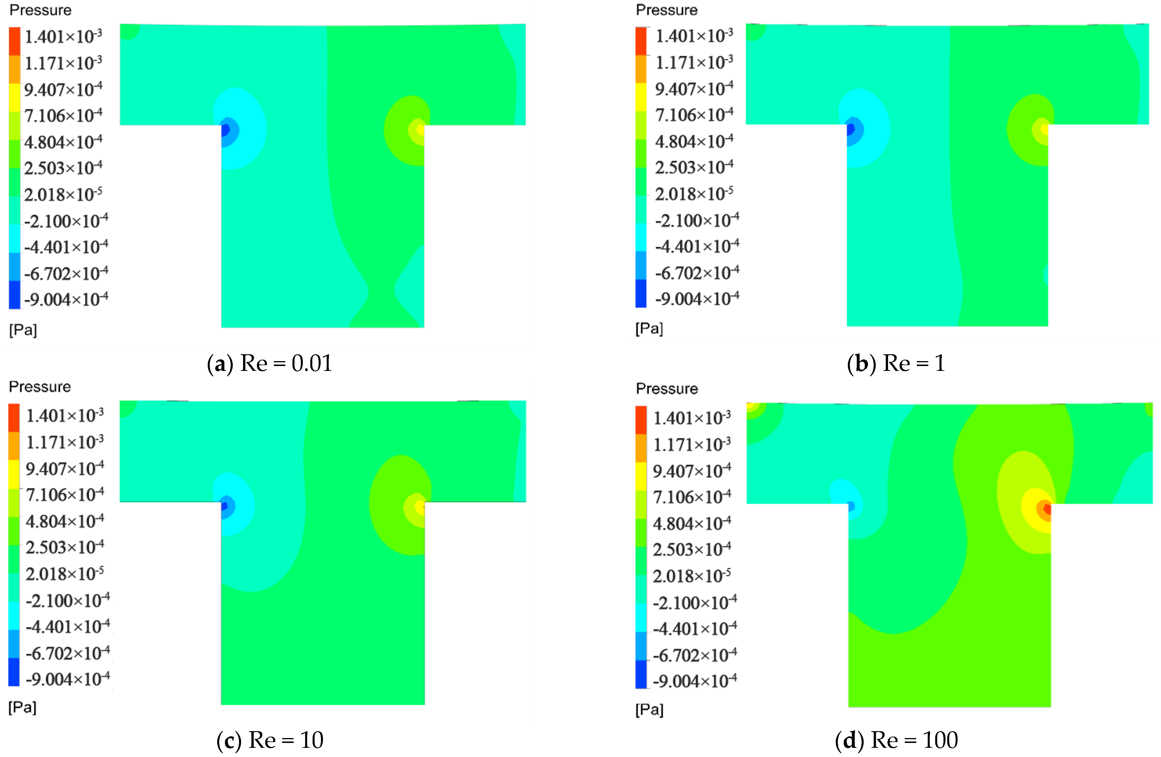
3.1. Inertia Effect

In general, the Reynolds number, which is the main parameter for determining the state of fluid flow, is defined as:
R e = ρ v l μ
where ρ is the fluid density, u is the dynamic viscosity, v is the linear velocity, and l is the feature length. For water-lubricated bearings, the Reynolds number equation can be organized as follows:
R e = ρ R j ω c μ
where Rj, c, and ω are the shaft diameter, bearing radius clearance, and shaft speed, respectively. Four Reynolds numbers of 0.1, 1, 10, and 100 are chosen to analyze the flow field characteristics inside the micro-cavity.
The Reynolds number is the vital factor influencing the inertia effect of micro-cavity pressure lubrication. Therefore, in order to investigate the inertia effect of the non-parallel friction pair, the effect of the Reynolds number on the pressure distribution of the friction pair is analyzed. The change in Re is achieved by a change in linear speed. In Chapter 3, Re denotes the Reynolds number unless otherwise specified. Figure 2 shows the contour of pressure distribution under different Reynolds numbers when the non-parallelism is 0.01. It can be seen from the figure that with the increase in Reynolds number, the maximum pressure in the friction pair increases, the area of the high-pressure region increases, and the area of the negative pressure region decreases. Due to the existence of non-parallelism, a convergence wedge is formed between the micro-cavities’ moving wall and the pressure inlet, thus forming a new high-pressure zone.
The pressure distribution curve of the moving wall under different Reynolds numbers with the same non-parallelism is shown in Figure 3. It can be seen from the figure that the general trend of pressure distribution under the inertia effect of non-parallel friction pairs is consistent with that under the inertia effect of parallel friction pairs [33]. As the Re increases, the pressure distribution curve moves upward, the proportion of the positive pressure area increases, and the load-carrying capacity increases. Compared with Figure 3b–d, it can be seen that with the increase in non-parallelism, the pressure rise inside the micro-cavity is limited.
In order to explore the influence of non-parallelism on lubrication performance under the same Reynolds number, the influence of non-parallelism on the pressure distribution curve of the moving wall of the friction pair under the same Reynolds number is shown in Figure 4. Under the same Reynolds number, the wedge effect caused by the non-parallelism makes the pressure at the inlet of the texture rise, thus increasing the load-carrying capacity of the friction pair. At the same time, the existence of non-parallelism will prevent the pressure distribution curve from moving up, reducing the load-carrying capacity of the friction pair. In addition, the increase in Reynolds number further limits the pressure rise in the micro-cavity. Figure 5 shows the velocity vector diagram in the micro-cavity with different Reynolds numbers when the non-parallelism is 0.1. It can be seen from the diagram that under the same non-parallelism, the larger the Reynolds number, the greater the downward velocity of the fluid in the micro-cavity, resulting in an enhanced plugging effect. Thus, the increase in non-parallelism leads to a stronger limiting effect on the pressure rise inside the micro-cavity.
In summary, the influence of the non-parallelism on the inertia effect of the friction pair depends on the wedge effect and the limit on the maximum pressure. The influence of non-parallelism on the load-carrying capacity of the friction pair at different Re is shown in Figure 6. It can be seen that at Re of 0.01, and 1, the wedge effect caused by the non-parallelism plays a dominant role, and the load-carrying capacity increases with the non-parallelism. However, at Reynolds numbers of 10 and 100, the load-carrying capacity decreases with the increase in non-parallelism, which is due to the fact that the presence of non-parallelism restricts the pressure rise, making the negative effect dominant.

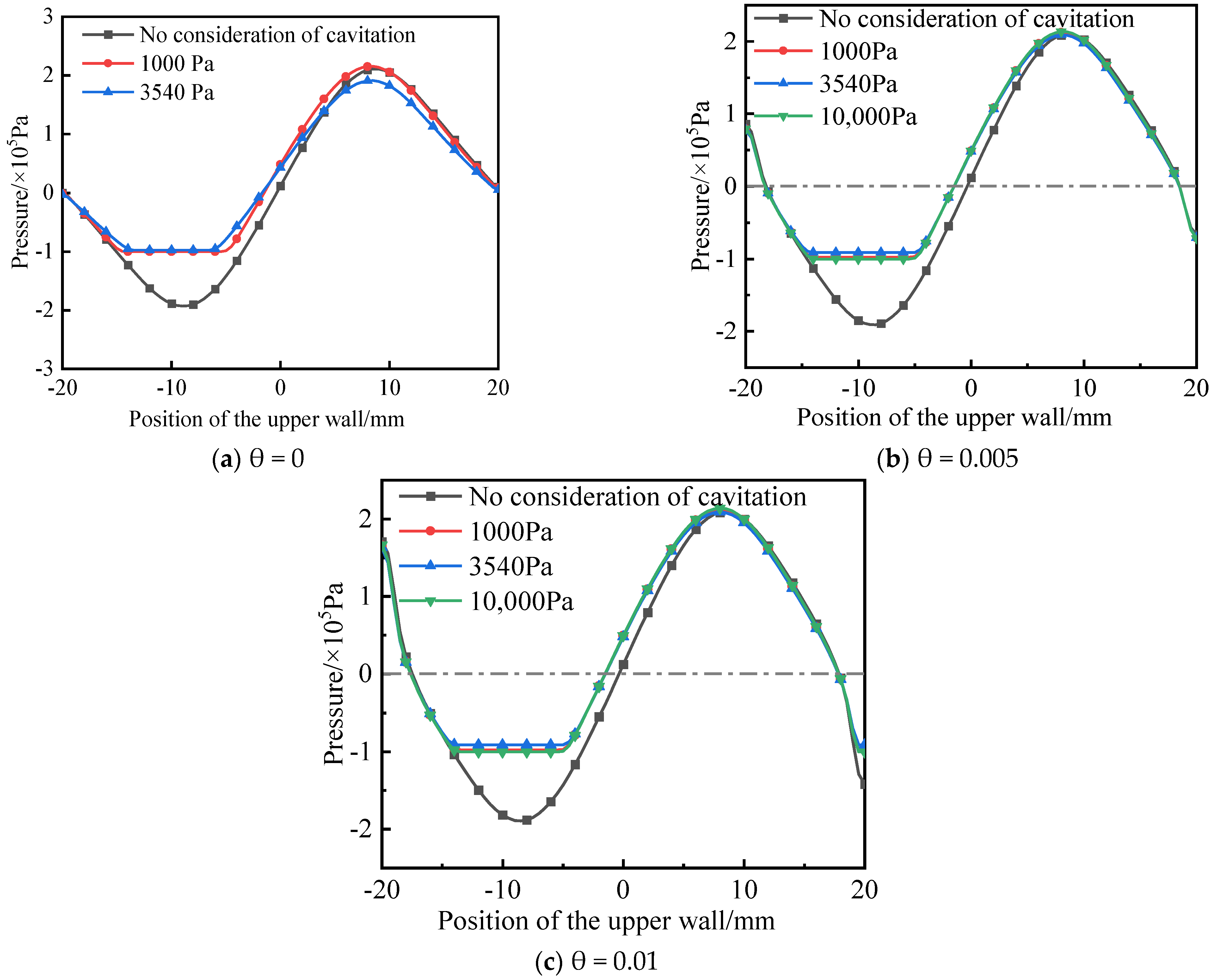
3.2. Cavitation Effect

In order to explore the cavitation effect under the same non-parallelism, the influence of the cavitation effect on the pressure distribution is analyzed. Figure 7 shows the pressure distribution contour of the friction pair under different cavitation pressures when the non-parallelism is 0.01. It can be seen from the figure that the cavitation effect causes the minimum negative pressure of the friction pair to increase, while the negative pressure proportion decreases, and the positive pressure proportion decreases slightly with the cavitation pressure. Figure 8 compares the influence of the cavitation effect on the pressure distribution curve of the moving wall of the micro-cavity between parallel friction pairs and non-parallel pairs with a degree of 0.005 and 0.01. From the figure, the general trend of the pressure distribution of the non-parallel friction pairs under the cavitation effect is consistent with that of the parallel friction pair, and the pressure reduction at the inlet of the micro-cavity region is limited.
Sun et al. [43] investigated the cavitation phenomenon of oil films in dynamically loaded journal bearings using high-speed photography and pressure measurements simultaneously, and the experimental results indicated that the pressure in the cavitation region was close to 0.5 MPa. According to the experimental results of Braun et al. [44] and Etsion et al. [45], the pressure in the cavitation region is close to the atmospheric pressure. It indicates that the cavitation pressure is uncertain for actual working conditions. In order to explore the influence of non-parallelism on the lubrication condition of the friction pair under the same cavitation pressure, the pressure distribution curves of the moving wall of the friction pair with different non-parallelisms are given in Figure 9 for the cavitation pressures of 3540 Pa and 10,000 Pa. The wedge effect caused by the non-parallelism significantly increases the pressure distribution at the pressure inlet of the friction pair of the non-parallel micro-cavity. After considering the cavitation effect, the maximum pressure in the high-pressure region caused by the micro-cavity has no obvious change with the increase of non-parallelism.
The percentage contribution of cavitation is defined as the “difference in load-carrying capacity before and after considering cavitation”/“load-carrying capacity when considering cavitation”, and the remaining part is the percentage contribution of other effects (for example, inertia effects and the inlet wedge effect). Figure 10 shows the contribution percentage of the cavitation effect and other effects to the load-carrying capacity under different non-parallelisms. It can be seen from the figure that, under the same non-parallelism, when the Re is small, the negative pressure has not reached the cavitation pressure, and other effects other than the cavitation effect account for 100%. With the Re, cavitation increases gradually, and the percentage of contribution to load-carrying capacity increases gradually.

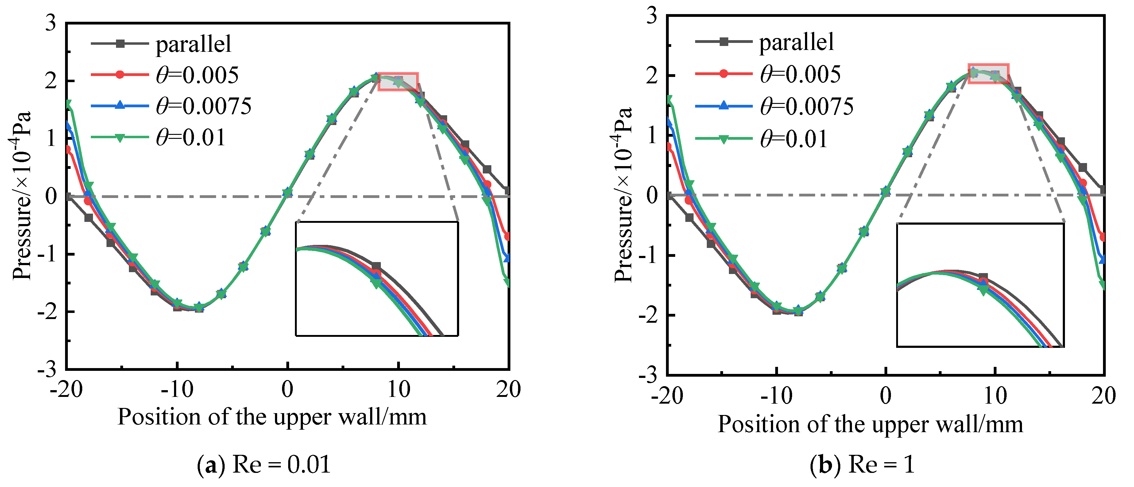
3.3. Inlet Wedge Effect

In order to explore the wedge effect of the inlet of the friction pair with the same non-parallelism, r was defined as the distance between the micro-cavity inlet and the pressure inlet boundary conditions, and it was taken as 0 mm, 5 mm, 10 mm, 15 mm, and 20 mm, respectively. Figure 11 shows the pressure distribution of the friction pair at different r when the non-parallelism is 0.01. As r increases, the overall pressure distribution in the non-parallel friction pairs decreases, while the proportion of the high-pressure zone decreases, the proportion of the negative pressure zone increases, and the load-carrying capacity of non-parallel friction pairs decreases. Figure 12 shows the pressure distribution curve of the moving wall surface under the inlet wedge effect when the degree of non-parallelism is 0.005 and 0.01. It can be seen that the moving wall pressure moves to the right and down with the increase at the inlet position. In addition, the area of the positive pressure area gradually decreases and the friction load-carrying capacity decreases, all of which are influenced by the inlet wedge effect.
In order to explore the influence of non-parallelism on the lubrication condition of friction pairs at the same inlet position, the determination of non-parallelism on the pressure distribution curve of the moving wall at the same inlet distance is shown in Figure 13. The wedge effect caused by non-parallelism significantly increases the pressure distribution at the pressure inlet, thus increasing the load-carrying capacity of friction pairs. As can be seen from Figure 13a–c, when the inlet distance is less than or equal to 10 mm, the existence of non-parallelism reduces the proportion of the negative pressure zone inside the micro-cavity and increases the proportion of the positive pressure zone, which improves the load-carrying capacity of the texture friction pair. In addition, the shorter the inlet distance, the more pronounced the pressure increase. As can be seen from Figure 13d,e, when the inlet distance is greater than 10 mm, the change trend is reversed. In addition, the larger the inlet distance is, the more obvious the reduction of non-parallelism on the pressure inside the micro-cavity is. Figure 14 shows the variation trend of load-carrying capacity with non-parallelism at different inlet positions. When the inlet distance is less than or equal to 10, the load-carrying capacity of non-parallel friction pairs increases with the increase in non-parallelism.

4. Conclusions

The textural friction pair models with different non-parallelisms are established, and the inertia effect, cavitation effect, and inlet wedge effect were analyzed, respectively. The following conclusions are drawn:
(1)
The wedge effect caused by the non-parallelism itself causes the pressure at the inlet of the micro-cavity to rise, thus increasing the load-carrying capacity of the friction pair.
(2)
The existence of non-parallelism limits the rise of the highest pressure of the inertia effect in the micro-cavity, and reduces the load-carrying capacity of the friction pair.
(3)
After considering the cavitation effect, the maximum pressure in the high-pressure zone caused by the micro-cavity does not change significantly, and the load-carrying capacity of the contact pair increases with the non-parallelism.
(4)
The presence of non-parallelism decreases the proportion of the negative pressure zone and increases the proportion of the positive pressure zone inside the micro-cavity, thus increasing the load-carrying capacity of the friction pair.
The research results and conclusions lay the theoretical foundation for further research and propose scale standards for water-lubricated bearings.

Author Contributions

Conceptualization, L.S. and Z.L. (Zhaozeng Liu); Validation, J.S., Y.W. and Z.L. (Zhaozeng Liu); Investigation, Z.L. (Zhen Li); Writing—review & editing, T.J. and Y.W. All authors have read and agreed to the published version of the manuscript.

Funding

This research is supported by the National Natural Science Foundation of China (No. 52176050), the General Program of Natural Science Foundation of Shandong Province (ZR2020ME174).

Data Availability Statement

Data are contained within the article.

Conflicts of Interest

The authors declare that the research was conducted in the absence of any commercial or financial relationships that could be construed as a potential conflict of interest.

References

  1. Wang, J.; Wang, J.; Tian, J.B.; Wang, G.W.; Yue, Z.H. Finite element analysis of load-carrying property of surface texture water-lubricated polymer bearings. Lubr. Eng. 2021, 46, 90–96. [Google Scholar]
  2. Zhang, P.Y.; Zhang, Y.H.; Hua, X.J. Lubrication design and development analysis of micro-texturing surfaces. Surf. Technol. 2021, 50, 14–32. [Google Scholar]
  3. Xie, Z.L.; Zhu, W.D. Theoretical and experimental exploration on the micro asperity contact load ratios and lubrication regimes transition for water-lubricated stern tube bearing. Tribol. Int. 2021, 164, 107105. [Google Scholar] [CrossRef]
  4. Xie, Z.L.; Shen, N.W.; Zhu, W.D.; Tian, W.; Hao, L. Theoretical and experimental investigation on the influences of misalignment on the lubrication performances and lubrication regimes transition of water lubricated bearing. Mech. Syst. Signal Process. 2021, 149, 107211. [Google Scholar] [CrossRef]
  5. Zhou, X.X.; Pang, X.J.; Yue, S.W.; Zhang, Y.; Zhang, H.; Yu, B. Tribological properties of combination of surface texture and ionic liquids. Tribology 2021, 41, 995–1003. [Google Scholar]
  6. Xie, Z.L.; Jian, J.; Stanislaw, W. The fluid-structure interaction lubrication performances of a novel bearing: Experimental and numerical study. Tribol. Int. 2023, 179, 108151. [Google Scholar] [CrossRef]
  7. Xie, Z.L.; Jian, J.; Zhao, B.; Zhang, J.; Xu, F. Theoretical and experimental research on the effect of bi-directional misalignment on the static and dynamic characteristics of a novel bearing. Mech. Syst. Signal Process. 2024, 208, 111041. [Google Scholar] [CrossRef]
  8. Gachot, C.; Rosenkranz, A.; Hsu, S.M.; Costa, H.L. A critical assessment of surface texturing for friction and wear improvement. Wear 2017, 372, 21–41. [Google Scholar] [CrossRef]
  9. Pettersson, U.; Jacobson, S. Influence of surface texture on boundary lubricated sliding contacts. Tribol. Int. 2003, 36, 857–864. [Google Scholar] [CrossRef]
  10. Yang, J.; Liu, Z.L.; Cheng, Q.C.; Liu, X.K.; Deng, T.Y. The effect of wear on the frictional vibration suppression of water-lubricated rubber slat with/without surface texture. Wear 2019, 426–427, 1304–1317. [Google Scholar] [CrossRef]
  11. Hamilton, D.B.; Walowit, J.A.; Allen, M. A theory of lubrication by micro irregularities. J. Basic Eng. 1966, 88, 177–185. [Google Scholar] [CrossRef]
  12. Annao, J.N.; Walowit, J.A.; Allen, C.M. Load support and leakage from micro asperity-lubricated face seals. J. Lubr. Technol. 1969, 91, 726–731. [Google Scholar] [CrossRef]
  13. Qiu, Y.; Khonsari, M.M. Experimental investigation of tribological performance of laser textured stainless steel rings. Tribol. Int. 2011, 44, 635–644. [Google Scholar] [CrossRef]
  14. Qiu, Y.; Khonsari, M.M. On the prediction of cavitation in dimples using a mass-conservative algorithm. J. Tribol. 2009, 131, 041702. [Google Scholar] [CrossRef]
  15. Zhang, J.Y.; Meng, Y.G. Direct observation of cavitation phenomenon and hydrodynamic lubrication analysis of textured surfaces. Tribol. Lett. 2012, 46, 147–158. [Google Scholar] [CrossRef]
  16. Meng, F.M.; Zhang, L. Effect of cavitation on tribological performances for textured surfaces. Adv. Mater. Res. 2012, 472–475, 391–394. [Google Scholar] [CrossRef]
  17. Meng, F.M. On influence of cavitation in lubricant upon tribological performances of textured surfaces. Opt. Laser Technol. 2013, 48, 422–431. [Google Scholar] [CrossRef]
  18. Bai, L.Q.; Meng, Y.G.; Zhang, V.R. Experimental study on transient behavior of cavitation phenomenon in textured thrust bearings. Tribol. Lett. 2016, 63, 27. [Google Scholar] [CrossRef]
  19. Li, Q.; Wang, Y.J.; Zhang, S. Investigation on hydrodynamic super position loading mechanism and micro-hydrodynamic effect of textured water-lubricated beating. Surf. Technol. 2019, 48, 180–187. [Google Scholar]
  20. Fowell, M.; Olver, A.V.; Gosman, A.D. Entrainment and inlet suction: Two mechanisms of hydrodynamic lubrication in textured bearings. J. Tribol. 2006, 129, 336–347. [Google Scholar] [CrossRef]
  21. Olver, A.V.; Fowell, M.T.; Spikes, H.A. ‘Inlet suction’, a load support mechanism in non-convergent, pocketed, hydrodynamic bearings. Proc. Inst. Mech. Eng. Part J J. Eng. Tribol. 2006, 220, 105–108. [Google Scholar] [CrossRef]
  22. Dobrica, M.B.; Fillon, M.; Pascovici, M.D. Optimizing surface texture for hydrodynamic lubricated contacts using a mass-conserving numerical approach. Proc. Inst. Mech. Eng. Part J J. Eng. Tribol. 2010, 224, 737–750. [Google Scholar] [CrossRef]
  23. Wang, J.; Yan, Z.; Fang, X. Observation and experimental investigation on cavitation effect of friction pair surface texture. Lubr. Sci. 2020, 32, 404–414. [Google Scholar] [CrossRef]
  24. Arghir, M.; Roucou, N.; Helene, M. Theoretical analysis of the incompressible laminar flow in a macro-roughness cell. J. Tribol. 2003, 125, 309–318. [Google Scholar] [CrossRef]
  25. Billy, F.; Arghir, M.; Pineau, G. Navier-stokes analysis of a regular two-dimensional roughness pattern under turbulent flow regime. J. Tribol. 2006, 128, 122–130. [Google Scholar]
  26. Sahlin, F.; Glavatskih, S.; Almqvist, T.R. Two dimensional CFD-analysis of micro-patterned surfaces in hydrodynamic lubrication. J. Tribol. 2005, 127, 96–102. [Google Scholar] [CrossRef]
  27. Feldman, Y.; Kligerman, Y.; Etsion, I.; Haber, S. The validity of the reynolds equation in modeling hydrostatic effects in gas lubricated textured parallel surfaces. J. Tribol. 2006, 128, 345–350. [Google Scholar] [CrossRef]
  28. Dobrica, M.B.; Fillon, M. About the validity of Reynolds equation and inertia effects in textured sliders of infinite width. Proc. Inst. Mech. Eng. J. Eng. Tribol. 2009, 223, 69–78. [Google Scholar] [CrossRef]
  29. Dobrica, M.B.; Fillon, M. Thermo hydrodynamic behavior of a slider pocket bearing. J. Tribol. 2006, 128, 312–318. [Google Scholar] [CrossRef]
  30. Cupillard, S.; Glavatskih, S.; Cervantes, M.J. Inertia effects in textured hydrodynamic contacts. J. Proc. Inst. Mech. Eng. J. Eng. Tribol. 2010, 224, 751–756. [Google Scholar] [CrossRef]
  31. Kraker, A.D.; Ostayen, R.A.J.V.; Rixen, D.J. Development of a texture averaged Reynolds equation. Tribol. Int. 2010, 43, 2100–2109. [Google Scholar] [CrossRef]
  32. Syed, I.; Sarangi, M. Hydrodynamic lubrication with deterministic micro textures considering fluid inertia effect. Tribol. Int. 2014, 69, 30–38. [Google Scholar] [CrossRef]
  33. Wang, Y.; Jacobs, G.; König, F.; Zhang, S. Investigation of Microflow Effects in Textures on Hydrodynamic Performance of Journal Bearings Using CFD Simulations. Lubricants 2023, 11, 20. [Google Scholar] [CrossRef]
  34. Khalil, M.F.; Kassab, S.Z. Ismail A S. Influence of inertia forces on the performance of turbulent externally pressurized bearings. J. Tribol. Int. 1992, 25, 17–25. [Google Scholar] [CrossRef]
  35. Woloszynski, T.; Podsiadlo, P.; Stachowiak, G.W. Evaluation of inertia effect in finite hydrodynamic bearings with surface texturing using spectral element solver. J. Tribol. Int. 2015, 91, 170–176. [Google Scholar] [CrossRef]
  36. Tonder, K. Dynamics of rough slider bearings: Effects of one-sided roughness/waviness. Tribol. Int. 1996, 29, 117–122. [Google Scholar] [CrossRef]
  37. Tonder, K. Hydrodynamic effects of tailored inlet roughnesses: Extended theory. Tribol. Int. 2004, 37, 137–142. [Google Scholar] [CrossRef]
  38. Tonder, K. Inlet roughness tribodevices: Dynamic coefficients and leakage. Tribol. Int. 2001, 34, 847–852. [Google Scholar] [CrossRef]
  39. Etsion, I.; Halperin, G. A laser surface textured hydrostatic mechanical seal. Tribol. Trans. 2002, 45, 430–434. [Google Scholar] [CrossRef]
  40. Xu, Y.F.; Zheng, Q.; Abuflaha, R. Influence of dimple shape on tribofilm formation and tribological properties of textured surfaces under full and starved lubrication. Tribol. Int. 2019, 136, 267–275. [Google Scholar] [CrossRef]
  41. Rom, M.; Müller, S. A new model for textured surface lubrication based on a modified Reynolds equation including inertia effects. Tribol. Int. 2019, 133, 55–66. [Google Scholar] [CrossRef]
  42. Marian, M.; Almqvist, A.; Rosenkranz, A.; Fillon, M. Numerical micro-texture optimization for lubricated contacts—A critical discussion. Friction 2022, 10, 1772–1809. [Google Scholar] [CrossRef]
  43. Sun, D.C.; Brewe, D.E. A high-speed photography study of cavitation in a dynamically loaded journal bearing. ASME J. Tribol. 1991, 113, 287–292. [Google Scholar] [CrossRef]
  44. Braun, M.J.; Hannon, W.M. Cavitation formation and modelling for fluid film bearings: A review. Proc. Inst. Mech. Eng. J. Eng. Tribol. 2010, 224, 839–863. [Google Scholar] [CrossRef]
  45. Etsion, I.; Ludwig, L.P. Observation of pressure variation in the cavitation region of submerged journal bearings. ASME J. Lubr. Technol. 1982, 104, 157–163. [Google Scholar] [CrossRef]
Figure 1. The single micro-cavity shape and boundary conditions (exaggerated non-parallelism).
Lubricants 12 00049 g001
Figure 2. Pressure distribution at different Re at θ = 0.01.
Lubricants 12 00049 g002
Figure 3. Pressure distribution under different Re.
Lubricants 12 00049 g003
Figure 4. Influence of non-parallelism on the pressure distribution of the moving wall at the same Re.
Lubricants 12 00049 g004aLubricants 12 00049 g004b
Figure 5. Velocity vector diagram at different Re.
Lubricants 12 00049 g005
Figure 6. The load-carrying capacity of a non-parallel friction pair.
Lubricants 12 00049 g006
Figure 7. Pressure distribution under different cavitation pressures at θ = 0.01.
Lubricants 12 00049 g007aLubricants 12 00049 g007b
Figure 8. Cavitation effect under the same non-parallelism.
Lubricants 12 00049 g008
Figure 9. Influence of non-parallelism on the pressure distribution of the moving wall under the same cavitation pressure.
Lubricants 12 00049 g009
Figure 10. Contribution of the cavitation effect and other effects to the load-carrying capacity.
Lubricants 12 00049 g010aLubricants 12 00049 g010b
Figure 11. The pressure distribution at different inlet positions at θ = 0.01.
Lubricants 12 00049 g011aLubricants 12 00049 g011b
Figure 12. The same inlet distance under the inlet suction effect.
Lubricants 12 00049 g012
Figure 13. Influence of non-parallelism on the pressure distribution of the moving wall at the same inlet position.
Lubricants 12 00049 g013aLubricants 12 00049 g013b
Figure 14. Load-carrying capacity at different inlet positions.
Lubricants 12 00049 g014
Table 1. Parameters of geometry and boundary conditions.
SymbolParameterValue
Textured geometry parameters
L/mmLength of the fluid domain40
d/mmWidth of textured zone20
h/mmDepth of textured zone20
h0/mmLiquid film thickness10
r/mmInlet position10
Lubrication medium parameters
ρl/ kg/m3Density of liquid phase water998.2
μl/Pa·sViscosity of liquid phase water10−3
ρv/kg/m3Density of vapor phase water0.5542
μv/Pa·sViscosity of vapor phase water1.34 × 10−5
pv/PaSaturated water vapor pressure3540
v/(m·s−1)sliding speed50
Pope/PaEnvironmental pressure101,325
Disclaimer/Publisher’s Note: The statements, opinions and data contained in all publications are solely those of the individual author(s) and contributor(s) and not of MDPI and/or the editor(s). MDPI and/or the editor(s) disclaim responsibility for any injury to people or property resulting from any ideas, methods, instructions or products referred to in the content.

