Article

Analysis of Water-Lubricated Journal Bearings Assisted by a Small Quantity of Secondary Lubricating Medium with Navier–Stokes Equation and VOF Model

1
School of Mechanical and Automotive Engineering, Qingdao University of Technology, Qingdao 266520, China
2
Key Lab of Industrial Fluid Energy Conservation and Pollution Control (Qingdao University of Technology), Ministry of Education, Qingdao 266520, China
*
Author to whom correspondence should be addressed.
Lubricants 2024, 12(1), 16; https://doi.org/10.3390/lubricants12010016
Submission received: 15 December 2023 / Revised: 4 January 2024 / Accepted: 5 January 2024 / Published: 7 January 2024
(This article belongs to the Special Issue Water-Lubricated Bearings)

Abstract

:
Due to the low viscosity of water, water-lubricated bearings are susceptible to significant wear and noise in demanding operating conditions. It has been demonstrated that a small quantity of secondary lubricating medium can improve the lubrication performance of water-lubricated contact surfaces and achieve the purpose of temporary risk aversion. As a further step, the feasibility of the proposed idea is experimentally validated on a water-lubricated bearing test bench. A numerical model that couples the N–S equation and the VOF model is then developed to investigate the behavior of the flow field lubricated by pure water and water with a small quantity of the secondary lubricating medium. This model provides the predictions of important quantities such as the load-carrying capacity, the secondary lubricating medium volume fraction and the contact pressure under different lubricated conditions. The results show that the secondary lubricating medium can enter into the contact region and improve the lubrication performance of water-lubricated bearings, especially at lower shaft rotational speeds. Therefore, the feasibility of our proposed idea is verified, which provides a promising approach to reduce the wear and friction of water-lubricated bearings when they encounter short-time severe working conditions.

1. Introduction

Water-lubricated bearings are increasingly popular due to their environmentally friendly properties. However, the water film thickness can easily be broken when water-lubricated bearings encounter short-time severe working conditions (sudden impact of the external load, the start-up and shut down period) [1] owing to the low viscosity of water; thus, the bearing wear failure, as well as the vibration and the noise of water-lubricated bearings, can be induced.
To address these issues and enhance the performance of water-lubricated bearings, researchers have conducted extensive studies from various perspectives, including bearing materials, bearing theory, bearing structure and the usage of new lubricating fluids [2,3].
The bearing bushing is a crucial component in water-lubricated bearings, which is designed to enhance efficiency and minimize the wear and vibration of water-lubricated bearings. Various fixed structures with grooves have been developed for this purpose. The key aspect of structural design lies in the groove and lubrication analysis of the bearing bushings, including the effect of journal misalignment on lubrication properties [4,5,6], the calculation of static and dynamic characteristics of water-lubricated bearings [7,8,9] and the influence of groove number and size on the stability of water-lubricated bearings [10,11,12]. Among these designs, the design of the bushing structure has always been controversial. The straight-fluted bearing is the most commonly used [13], featuring load-carrying lands or staves that facilitate partial hydrodynamic lubrication and low load capacity. Spiral grooved bushings, studied by Zhou [14], displayed a vortex effect inside the grooves that facilitates impurity discharge such as sediment. Herringbone groove bearings, as found by Feng [15], offered maximum load capacity, followed by straight groove and spiral groove bearings. Dong’s study [16] revealed that soft materials, like rubber, exhibited stick–slip friction and a fold morphology under water lubrication, but it remained unclear whether this phenomenon applies to water-lubricated bearings. All of these types of structures play important roles in improving the performance of water-lubricated bearings, but instability generated by the complex structure urges researchers to find simpler ways to reduce the abrasion of water-lubricated bearings.
The development of new materials for bushings is another commonly used approach by researchers to improve the lubrication performance of water-lubricated bearings. Common materials used for water-lubricated bearings include lignum vitae, rubber, modified polytetrafluoroethylene and composite polymer materials. In addition to these, high-performance materials for water-lubricated bearings are constantly being synthesized, such as the Thordon and the Feroform, which are widely used in water-lubricated bearings [17]. Yang [18] synthesized urea formaldehyde (UF) microcapsules using in situ emulsion polymerization and added them to a high-density polyethylene (HDPE) matrix to reduce the coefficient of friction (hereafter ‘COF’) and adhesion wear of water-lubricated bearings. Liang [19] introduced polyacrylonitrile (PAN) fiber as a reinforcement material to further enhance the tribological properties of water-lubricated bearings, thus improving their service life. Although these materials have been proven to have a low COF and better wear resistance, the potential for existing materials to improve the performance of water-lubricated bearings is limited, and new materials need to be developed.
Traditional theoretical analyses of water-lubricated bearings typically utilize lubrication theory based on the Reynolds equation [1,20,21]. While these methods can yield reasonable results, complex bearing models and potential parameter selection errors may lead to simulation result deviations. Additionally, traditional methods often focus on single-phase flow, rather than multiphase flow, even though water-lubricated bearings can easily wear out when working in water with high sediment content or a cavitation environment.
In contrast to traditional methods, our previous work [22,23] proposed a new approach: adding a small quantity of secondary lubricating medium in real time to the water when the water-lubricated contact surfaces encounter severe working conditions; thus, the film-forming ability of the water can be enhanced and the COF between the shaft surface and bearing surface can be decreased.
We have demonstrated the feasibility of this approach in a block-on-ring test rig. In this work, we conduct experiments on a water-lubricated bearing test bench to investigate the applicability of this approach in water-lubricated bearings.
According to the experiments, the widely used VOF method [24] is chosen to track the interface between the water and the secondary lubricating medium. By combining it with the Navier–Stokes (hereafter ‘N–S’) equation, a numerical model is established with Matlab R2022b to simulate the flow field in water-lubricated bearings after a small amount of secondary lubricating medium is injected, thus theoretically verifying the feasibility of the proposed approach for water-lubricated bearings. Additionally, the influence of the proposed idea on various parameters (the pressure distribution, the load-carrying capacity, etc.) is also explored.

2. Geometry Description

Figure 1 depicts two different types of water-lubricated bearings. Figure 1a displays the typical geometry of commonly used water-lubricated bearings, while Figure 1b shows the new-type water-lubricated bearing geometry studied in our work, which includes a small quantity of secondary lubricating medium supply structure added to the bearing. Pure water is supplied from one side for lubrication (as shown in Figure 1), and the oil is supplied from the oil inlet to mix with pure water for lubrication (as shown in Figure 1b).
Table 1 presents the relative parameters of these two types of water-lubricated bearings, which are the same as those used in industrial applications.

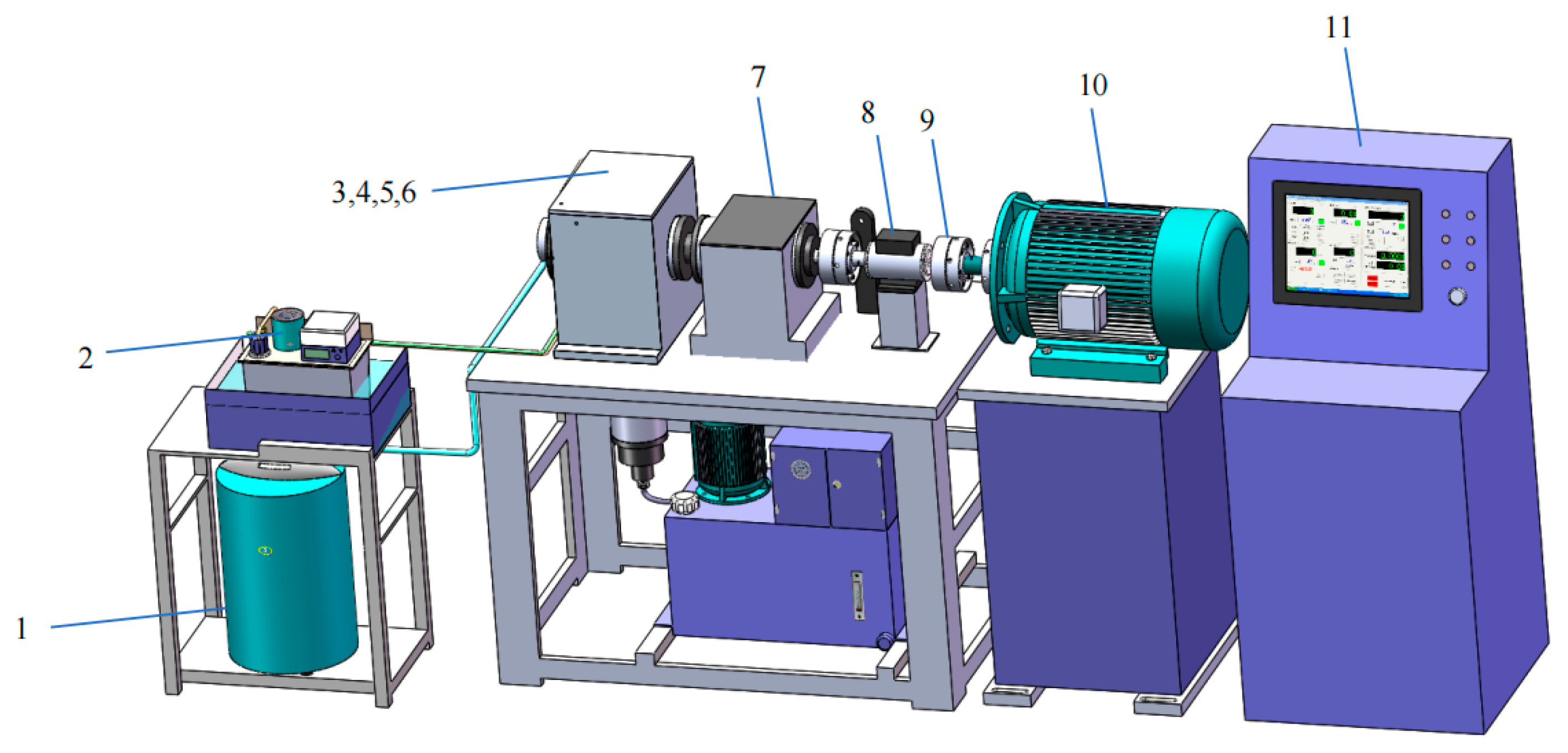
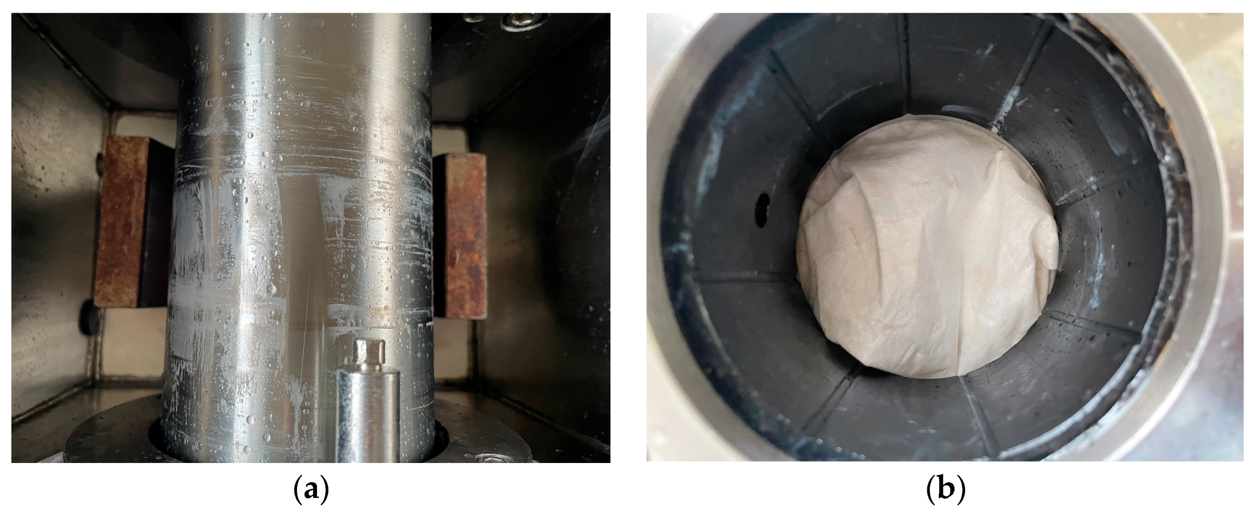
3. Experimental Verification
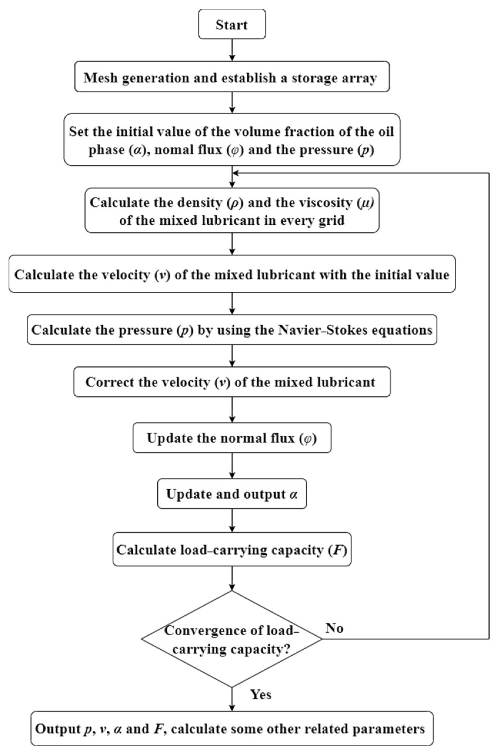
The feasibility of the proposed idea on the water-lubricated bearing is carried out. The schematic diagram of the water-lubricated bearing test bench used in the experiment is shown in Figure 2.
It has been observed that the lubrication performance of the micro-emulsified oil droplets is effectively utilized by using O/W (oil-in-water) emulsion as a lubricant, and the application of O/W emulsion is already found in many fields such as metal processing. The film-forming theories about the O/W (oil-in-water) emulsion have been proposed in [25,26], such as plate-out, dynamic concentration and secondary emulsification. It should be noted that within the framework of our proposed concept, the aforementioned O/W film-forming theories undeniably contribute to our research by employing emulsifying oil as a small quantity of secondary lubrication medium. Meanwhile, our previous work [27] has also proved the effectiveness of emulsifying oil in decreasing the COF between two surfaces on the block-on-ring test rig. Therefore, the secondary lubricating medium used in the experiment is an emulsifying oil (provided by Zhongkerunmei Lubrication Materials Technology Co., Ltd., Qingdao, China).
As we mentioned in our previous work [22], contact between the bearing surface and the shaft surface occurs under the mixed lubrication regime at some severe working conditions, such as heavy impact load and low rotational speeds, and the ring rotational speed for the mixed lubrication regime lies in the interval of 50 r/min to 1500 r/min under two different applied loads. In an effort to determine whether a modest injection of secondary lubricating medium within this contact can alter the COF between the shaft and the bearing surfaces, shaft rotational speeds of 100 r/min and 200 r/min are selected with the applied load of 500 N, while variations in the COF are subsequently monitored.
Before the test bench starts up, water from the water supply system (No.1 in Figure 2) is pumped into the sealing chamber (No.5 in Figure 2) through the inlet at the sealing chamber, and another water pump in the water supply system is used to draw the water from the chamber into the waste tank through the outlet. Thus, the open-water environment can be simulated.
Once the test bench has started up (ω = 100 r/min, P = 500 N) and the COF has become steady (after a running-in period of approximately 300 s), 8.8 mL of emulsifying oil is injected at a constant rate (2.2 mL/s) over a period of 4 s, and the oil feeding pressure is 2 MPa. The experiment is conducted three times while paying close attention to the careful cleaning of both the bearing and shaft surfaces using petroleum ether and ethyl alcohol, with the COF being recorded on each occasion. In order to depict detailed information about the test curve, data from the second repetition test of the experiment are selected as the typical outcome for plotting the COF curve, which is consistent with our previous work [22].
In Figure 3a, we can observe the variation in COF over a period of 600 s when a small amount of emulsifying oil is injected into the water-lubricated bearing at the shaft rotational speed of 100 r/min. The injection of emulsifying oil instantaneously reduces the COF between the two surfaces in contact from 0.24 to roughly 0.19 and becomes stable, which is lower than the COF observed during pure water lubrication.
By increasing the shaft rotational speed to 200 r/min while keeping the other experimental conditions unchanged, the variation in the COF is recorded, as shown in Figure 3b. Similar to the observations in Figure 3a, the COF initially decreases from 0.23 to 0.175 upon injecting the emulsifying oil. Following some fluctuations, the COF subsequently increases before stabilizing around 0.196, which is still lower than the COF in pure water lubrication.
Figure 4 shows the conditions of the journal and bearing after the experiment. It can be observed that some emulsified oil is stuck on the surfaces of the bearing and shaft, and this adherence continues to contribute to lubrication even after the injection of emulsified oil is ceased. This explains why, as depicted in Figure 3, the stable COF following the injection of emulsified oil remains lower than that of pure water lubrication.
These observations suggest that the emulsifying oil can assist with the lubrication of the contact surfaces and increase the film-forming capacity of water. Therefore, our proposed idea has been validated regarding water-lubricated bearings.
For a better understanding of the synergistic lubrication of water and the secondary lubricant in water-lubricated bearings, after a small quantity of secondary lubricating medium has been injected, a numerical model is established. It should be noted that when a small quantity of secondary lubricating medium is introduced into water-lubricated bearings, the dispersion of the secondary lubricating medium is dependent on the velocity of the flow field. Furthermore, the combined effect between the water and the secondary lubricating medium can impact the density and viscosity of the mixed lubricant. To model these phenomena, the N–S equation and VOF model are integrated, with Matlab 2022Rb programming utilized.

4. Methodology

4.1. Governing Equations

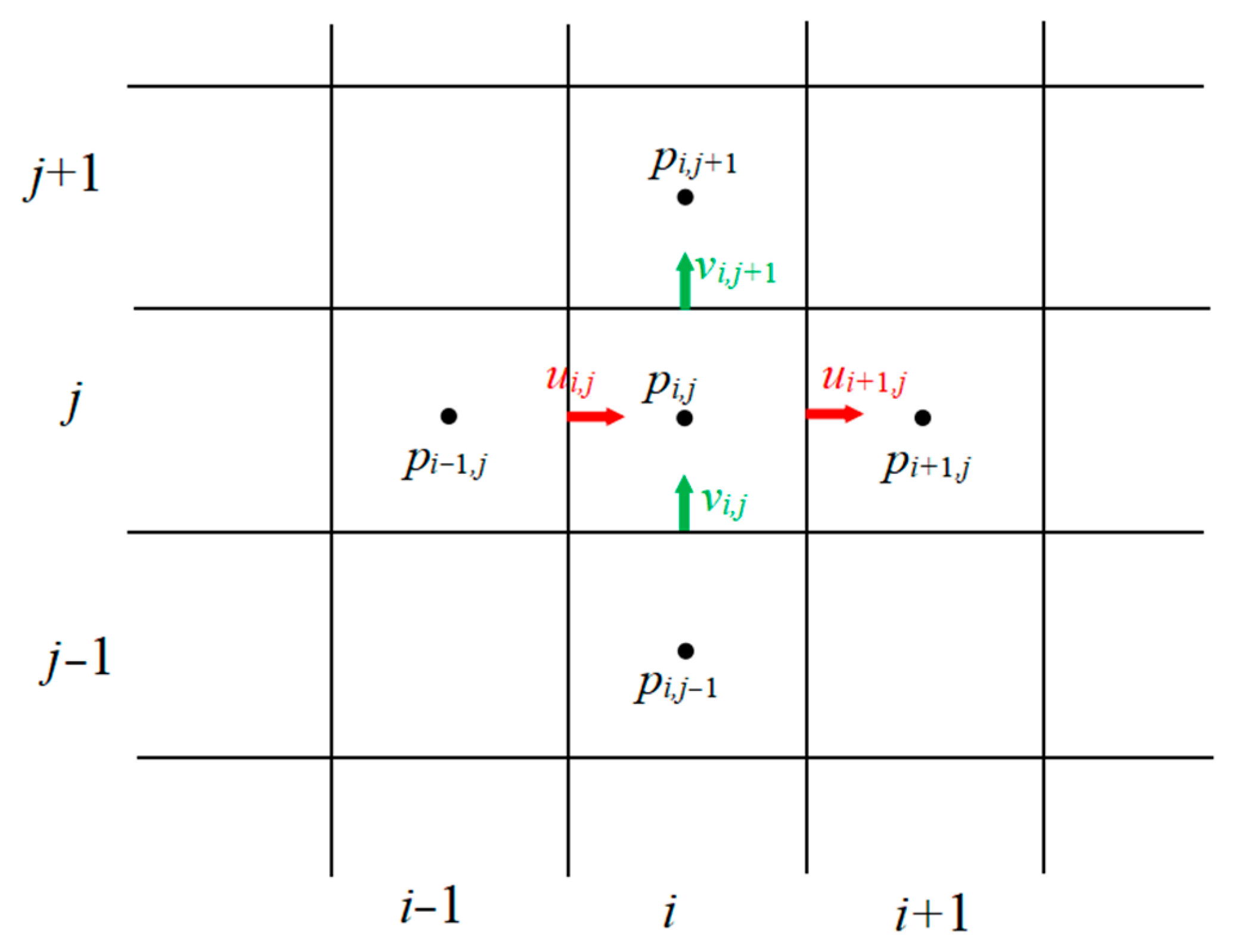
4.1.1. Navier–Stokes (N–S) Equation

In this work, we mainly focused on the spatial distribution of the oil; the incompressible steady-state N–S equations are then used in this paper, which are
· ( ρ U U ) = p + μ 2 U
· ( ρ U ) = 0 ,
where p is pressure; ρ is density; μ is viscosity and U is the velocity of the flow.
The integrated form of Equations (1) and (2) in any closed region are
( ρ U ( U · d s ) ) = ( p d s ) + ( μ U · d s )
( ρ U · d s ) = 0
By using the finite volume method, Equations (3) and (4) can be discretized as
k = 0 n f a c e s U i k ( ρ U i k · S i k ) = k = 0 n f a c e s ( ρ S i k ) + k = 0 n f a c e s ( μ U · S i k )
k = 0 n f a c e s ( ρ U i k · S i k ) = 0 ,
where i represents the number on the grid and k is the number on the edge of the grid.
In order to prevent oscillations in pressure during the discretization, the staggered grid method (Figure 5) is used, which stores velocities at locations offset from the pressure storage locations in their respective directions, and each of the pressure and the velocity components have separate control volumes.
Due to the influence of water velocity on the distribution of the secondary lubricating medium, not only the flow velocity change along the circumferential and the axial directions should be considered, but the flow velocity change along the film thickness direction needs to be considered in this situation. However, the dimension in the direction of film thickness is smaller than the dimensions in both circumferential and axial directions, and the computation cost of a 3D model is very high in the present work. Thus, a quasi-2D model is then established, and Equations (5) and (6) can then be written as
k = 0 n f a c e s U i k φ S i k h i k = k = 0 n f a c e s ( ρ S i k h i k ) + k = 0 n f a c e s ( μ U · S i k h i k )
k = 0 n f a c e s φ i k S i k = 0 ,
where φ represents normal flux and can be calculated as follows:
φ = ρ U i + ρ U k 2 · S i k S i k
Due to the roughness and the nonparallelism of the shaft surface and the bearing surface, additional fluxes can be caused by the pressure and the viscous forces, which will also modify the momentum source term in Equation (7) to the form:
μ U · S = μ A U n  
In addition, the distribution of the flow velocity along the film thickness direction can be supposed to satisfy the Couette flow, then the flow velocity can be written as
U = a y 2 + b y + c
By considering the rotational speed of the bearing as zero, the rotational speed of the shaft is r × ω , and the average flow velocity between the shaft and the bearing is regarded as the flow velocity along the film thickness, so that
U = 3 r × ω 6 U ¯ h 2 y 2 + 6 U ¯ 2 r × ω h y
By combining Equations (10) and (12), the momentum source can be written as
μ A U n   = μ A 6 r × ω 12 U ¯ h
Then, Equation (7) is revised as
k = 0 n f a c e s U i k φ S i k h i k = k = 0 n f a c e s ρ S i k h i k + μ A 6 r × ω 12 U ¯ h i a h i k ,
where a represents the average value.
The film thickness equation used in the calculation is:
h = c + e c o s ( θ ψ ) ,
where c is the radial clearance, e is the eccentric distance and ψ is the attitude angle.

4.1.2. Volume of Fluid (VOF) Method

As we mentioned in our previous work [22], the volume fraction of a phase is indicated by α in the VOF method, which is defined as
α = 1   computational   cell   is   fully   filled   with   the   water 0   computational   cells   are   fully   filled   with   the   secondary   lubricating   medium 0 < α < 1   interface   cells
It can be calculated by using the steady-state advection equation:
· ( α u ) = 0
By discretizing the advection equation in the quasi-2D model, Equation (16) becomes
k = 0 n f a c e s α i k φ i k S i k h i k h i a = 0
The density and the viscosity of the fluid then can be calculated using the following equations:
ρ = α 1 ρ 1 + α 2 ρ 2
μ = α 1 μ 1 + α 2 μ 2 ,
where the subscripts 1 and 2 represent two different fluids. For each computational cell, α o + α w = 1 , where o means oil and w means water.
Values of the density and the viscosity of the mixed lubricant, as solved by Equations (16)–(19), are then used in Equations (8), (9) and (14) to establish the quasi-2D two-phase medium lubrication model. Equations (8) and (14) are then used to calculate the distribution of the velocity and the pressure for the flow field in the bearing by implementing the SIMPLE method.

4.1.3. Load-Carrying Capacity

The load-carrying capacity generated by the fluid acting on the bearing can be expressed as [28,29]
F = z 1 z 2 θ 1 θ 2 p d θ d z ,
where θ is circumference direction and z is the axial direction.
The flow chart of the entire calculation process is shown in Figure 6.

4.2. Boundary Conditions

In this work, the Reynolds boundary conditions are used in the analysis:
p ( θ , 0 ) = p ( θ , L ) = 0
p ( θ 0 , z ) = 0 , p ( θ 0 , z ) θ = 0 ,
where L is the length of the bearing and θ0 is the film rupture position in the circumferential direction.
Using this boundary condition ensures that the pressure and its gradient are zero at the circumferential initial point of the journal bearing and that the rupture boundaries are satisfied.

4.3. Mesh Generation

Figure 7 illustrates the meshing of the flow field used in the present work. Due to the large number of configurations requiring calculation under different parameters, a two-dimensional grid generation program is developed specifically for this purpose. Due to the large amount of calculations near the oil inlet and boundary positions, denser mesh grids are employed to guarantee the simulation accuracy.

5. Model Verification

FLUENT 2020 R2 is used to verify the reliability of the established quasi-2D model. The quasi-2D model and the FLUENT are both run under the same working conditions (ω = 300 rpm, vw = 0.03 m/s, vo = 0 m/s), and the comparison of the water flow velocity along the direction of the film thickness (red arrow in Figure 8) is depicted in Figure 9. It is clear that the water flow velocity calculated by the quasi-2D model is consistent with the values from the FLUENT, thereby verifying the accuracy of the established quasi-2D model.

6. Results and Discussion

Table 2 provides comprehensive information on the simulation parameters, wherein two phases considered in the simulation are water phase and emulsifying oil phase, the radial clearance is preselected as 70 μm and the eccentricity ratio is set to 0.9 during the simulation process. It should be recognized that although this gap size varies from the actual experimental ones in the CFD calculation, it can still provide valuable positions about flow field phenomena and the volume fraction of the oil between the bearing and the shaft for subsequent analysis.

6.1. Different Lubrication Conditions (ω = 100 r/min, vw = 0.03 m/s, Oil Flow Rate = 125 μL/s)

Figure 10 presents the pressure distribution when the journal bearing is lubricated by pure water and water with a small quantity of emulsifying oil (water is set to enter from the bottom of the plot and exit from the top of the plot, as in other cases). Even if the simulation is under the hydrodynamic lubrication regime, the maximum value of pressure significantly increases as the secondary lubricating medium is injected into the water-lubricated bearing.
Meanwhile, the pressure distribution becomes more concentrated towards the center after injecting the emulsifying oil, creating a distinctive diamond-like pattern compared to the “cashew nut” shape shown in [30]. This difference could be attributed to the increased comprehensive viscosity of the mixed lubricant caused by the added emulsifying oil. Moreover, due to the use of Reynolds boundary conditions during the simulation, the pressure gradually decreases while spreading outwards as a result of the viscosity, leading to a distribution that is centered towards the bearing’s center.
According to the value of the pressure, the calculated load-carrying capacity in the journal bearing lubricated by pure water and water with a small quantity of emulsifying oil is 256 N and 1621 N, respectively, which illustrates that the load-carrying capacity becomes larger with the help of the injected secondary lubricating medium. Therefore, the load-carrying capacity will also be augmented along with the injection of the secondary lubricating medium when the water-lubricated bearing is under the mixed lubrication regime. The increase in load-carrying capacity usually accompanies an increase in the thickness of the lubrication film, thereby reducing the actual contact area between the contacting surfaces. Perhaps that is why the COF decreases immediately with the actual contact area reduction after injecting the emulsifying oil in the experiment.

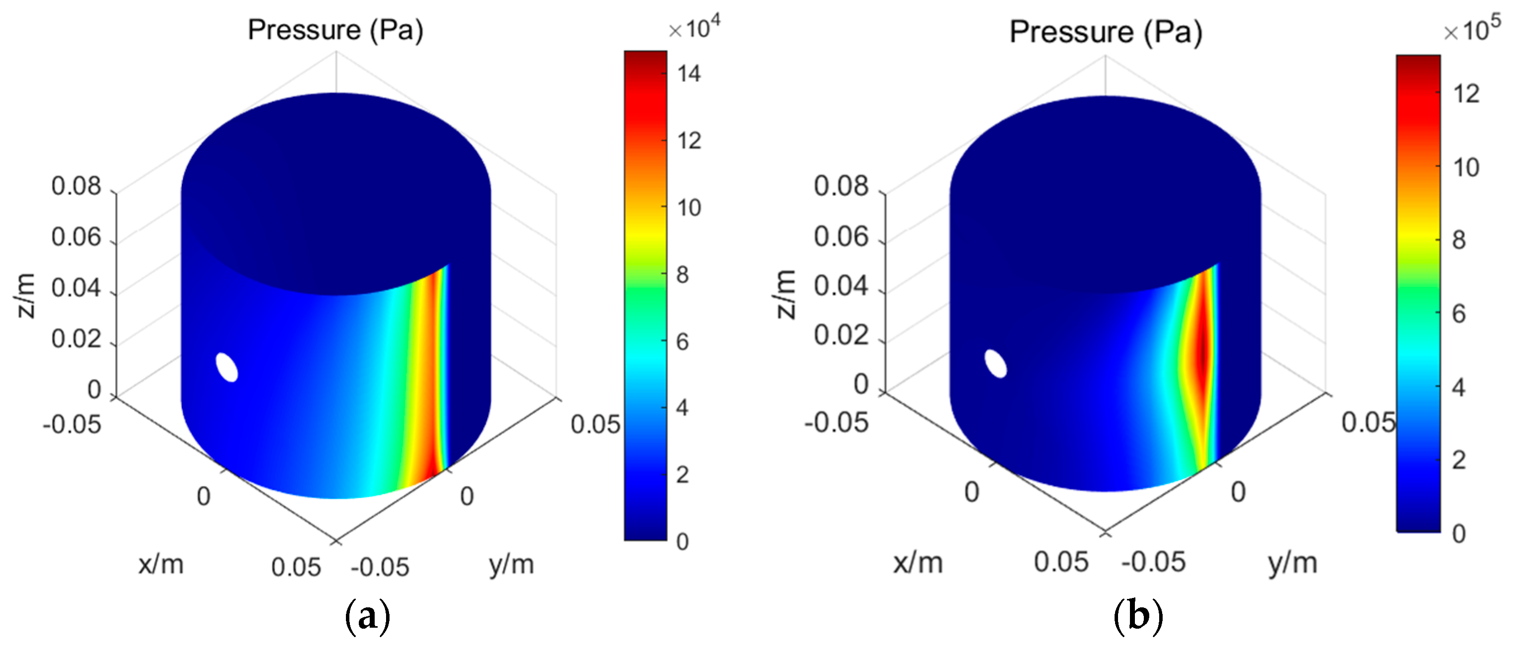
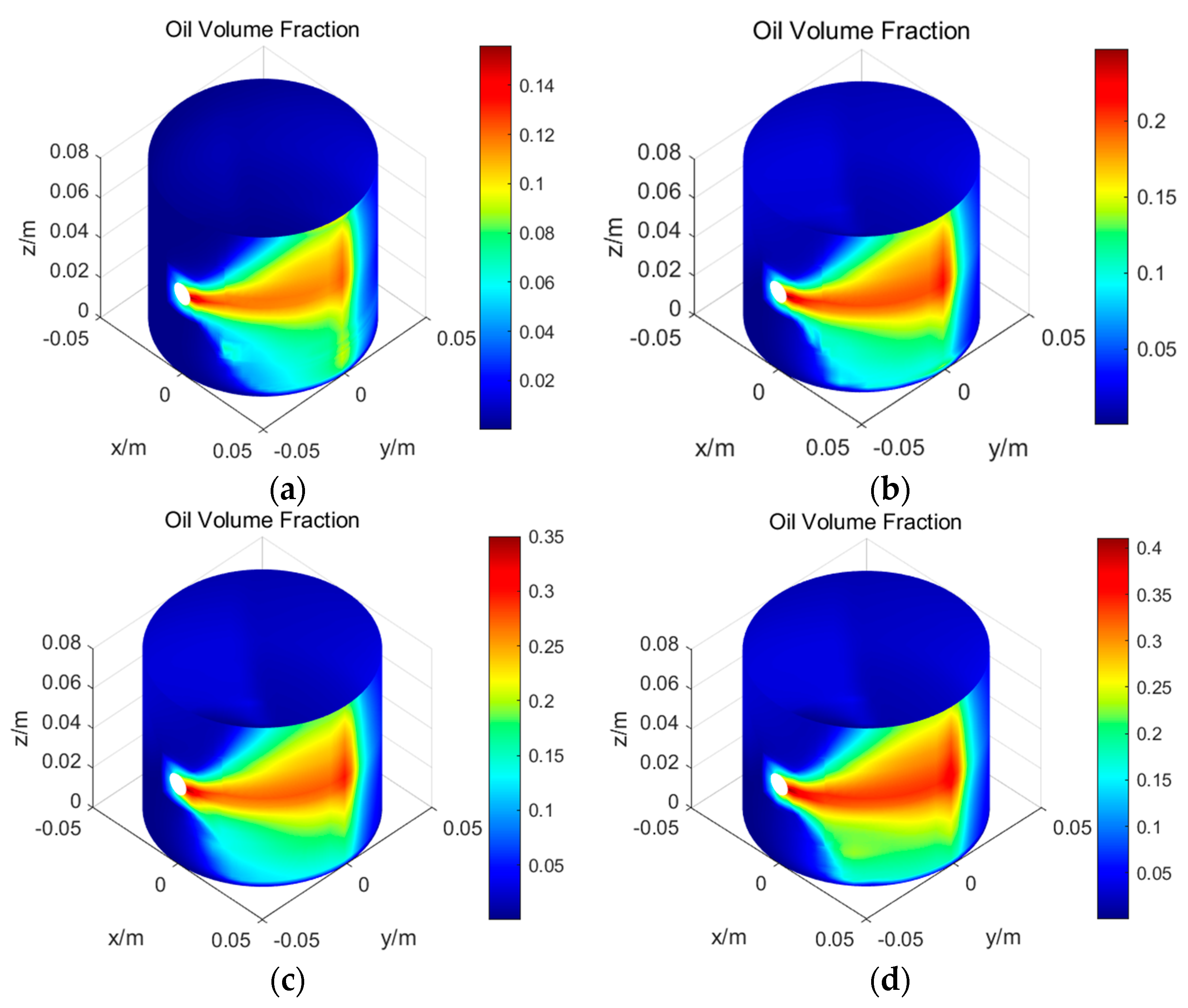
6.2. Different Water Flow Velocity (ω = 100 r/min, Oil Flow Rate = 125 μL/s)

The emulsifying oil distribution under different water flow velocities is illustrated in Figure 11. It can be observed that there are side leakages and a decreasing distribution area in the secondary lubricating medium, which could be caused by the force that water exerts on the secondary lubrication medium becoming stronger as the water flow velocity increases, consequently preventing the entry of the secondary lubricating medium into the contact region. This indicates that the water flow velocity is a critical factor for the successful delivery of the secondary lubricating medium to the contact region.
Figure 12 displays the pressure distributions for different water flow velocities, where the diamond-shaped pressure distribution exists regardless of water flow velocities. The calculated load-carrying capacities with different water flow velocities for a water-lubricated bearing are 1867 N, 1621 N, 1664 N and 1601 N, respectively, displaying an overall decreasing trend, which is caused by the side leakage and decreasing distribution area of the secondary lubricating medium.
The velocity field of the fluid field for different water flow velocities is shown in Figure 13. It can be seen that the velocity direction of the flow field points towards the water outlet with an increase in water flow velocity, which indicates that the influence of the water flow on the overall flow field strengthens accordingly. At the same time, the velocity magnitude of the flow field also changes; the location of the maximum value of velocity in the overall flow field begins to shift from the contact region toward the water outlet as the flow progresses. However, there is always a region with the highest water flow velocity at the inlet of the water, which is because the water inlet at the water-lubricated bearing system is a necking area in the open-water environment, leading to the increase in the water flow velocity.
Figure 14 shows the magnified velocity field around the secondary lubricating medium injection zone under different water flow velocities. It can be seen that reverse flow is mostly concentrated at the water inlet and around the injection zone regardless of the water flow velocities, and the reverse flow zone is increased and the reverse flow velocity is enhanced as the water flow velocity increases. This may be because when the secondary lubricating medium is injected into a stable flow field, the injected secondary lubricating medium acts as an obstacle in the stable flow field. This can lead to a sudden decrease in water flow velocity near the secondary lubricating medium injection zone and the formation of vortex structures, which can affect the surrounding fluid and cause reverse flow. As the water flow velocity increases, the intensity of vortices becomes stronger, resulting in the formation of more vortices in the fluid field. When these vortices continuously expand and merge, the reverse flow zone also grows. Additionally, the surrounding fluid is easily drawn into the vortices due to the inertia effect of high-speed water flow, further enhancing the reverse flow phenomenon.
Therefore, reverse flow should be avoided as much as possible when injecting the secondary lubricating medium, especially when the water flow velocity is high. The oil inlet where the secondary lubricating medium is injected in Figure 1 should be located in the middle of the bearing or near the outlet of the flow field.
It can also be concluded that there is still some mixed lubricant breaking through the reverse flow and entering the contact region to participate in the lubrication, which can reduce the friction and wear between contact surfaces.

6.3. Different Oil Flow Rate (ω = 100 rpm, vw = 0.03 m/s)

The influence of the oil flow rate on the flow field is discussed in this part. Figure 15 shows the oil distribution for different oil flow rates. The distribution area of the secondary lubricating medium remains relatively stable across different oil flow rates, as the water flow velocity remains unchanged. However, the volume fraction of the secondary lubricating medium in the contact area increases with the increased flow rate of the secondary lubricating medium.
Figure 16 is the pressure distribution under different oil flow rates, and the corresponding load-carrying capacities are 989 N, 1621 N, 2247 N and 2778 N, which is proportional to the oil flow rate.
Figure 17 and Figure 18 show the distribution of the velocity field in the flow field under different oil flow rates. It can be found that the distribution of the velocity vector and the reverse flow are basically the same under these four oil flow rates, indicating that the oil flow rate has little effect on the flow field. Therefore, if environmental friendliness is ensured, more secondary lubricating medium can be injected into the contact surfaces to improve the lubrication status between the bearing surface and the shaft surface.

7. Conclusions

(1) Our proposed idea has been practically examined through experiments conducted on the water-lubricated bearing test bench. The results reveal that a small amount of emulsifying oil can significantly reduce the COF between the bearing surface and the shaft surface under the high load and low shaft rotational speed conditions, demonstrating the effectiveness of the proposed idea on water-lubricated bearings.
(2) A numerical quasi-2D model using MATLAB R2022b has been established, which couples the N–S equation and VOF method for simulation purposes.Based on the simulation results, reverse flow exists around the injection zone regardless of the water flow velocities; the reverse flow is mostly concentrated at the water inlet and secondary lubricating medium injection zone, which gives guidance when choosing the secondary lubricating medium injection location.
(3) Despite the reverse flow, the secondary lubricating medium can still penetrate into the contact region and participate in lubrication under water environments, which can lead to a noticeable decrease in COF between the bearing surface and shaft surface.
(4) The flow field condition remains unchanged as the oil flow rate increases, indicating that the oil flow rate has little effect on the flow field.Therefore, if environmental friendliness is ensured, more secondary lubricating medium can be injected into the contact surfaces to improve the lubrication status between the bearing surface and the shaft surface.
(5) These simulation results can provide theoretical guidance for the further development of bench experiments.Since water-lubricated bearings are under a mixed lubrication regime when the encounter severe working conditions, the mixed lubrication model for water-lubricated bearings with secondary lubricating medium will be programmed in the future.

Author Contributions

Conceptualization, F.G. and X.Z.; methodology, X.Z.; software, X.Z.; validation, T.Y., H.J. and W.D.; formal analysis, X.Z. and P.L.; investigation, X.Z. and L.M.; writing—original draft preparation, X.Z.; writing—review and editing, X.Z., F.G. and P.L. All authors have read and agreed to the published version of the manuscript.

Funding

This research is supported by the National Natural Science Foundation of China (No. 52205200, No. 52375190 and No. 52375190); Taishan Scholar Talents Project from Shandong Province (No. TS20190943); Qingdao Postdoctoral Innovation Project (No. QDBSH20220202008) and Shandong Provincial Natural Science Foundation (No. ZR2021QE214).

Data Availability Statement

The data that support the findings of this study are available from the corresponding author upon reasonable request.

Conflicts of Interest

The authors declare that they have no known competing financial interests or personal relationships that could have appeared to influence the work reported in this paper.

Nomenclature

Cradial clearance
Eeccentric distance
Fload-carrying capacity
Knumber on the edge of the grid
Lbearing length
Ppressure
Inumber on the grid
Uvelocity of the flow
vovelocity of the oil injection
vwvelocity of the water flow
zaxial direction
ωshaft rotational speed
μviscosity
θcircumferential direction
θ0film rupture position in the circumferential direction
ρdensity
φnormal flux
αvolume fraction of the phase
ψ attitude angle

References

  1. Gong, J.; Jin, Y.; Liu, Z.; Jiang, H.; Xiao, M. Study on influencing factors of lubrication performance of water-lubricated micro-groove bearing. Tribol. Int. 2019, 129, 390–397. [Google Scholar] [CrossRef]
  2. Urreta, H.; Aguirre, G.; Kuzhir, P.; de Lacalle, L.N.L. Seals based on magnetic fluids for high precision spindles of machine tools. Int. J. Precis. Eng. Manuf. 2018, 19, 495–503. [Google Scholar] [CrossRef]
  3. Urreta, H.; Aguirre, G.; Kuzhir, P.; de Lacalle, L.N.L. Actively lubricated hybrid journal bearings based on magnetic fluids for high-precision spindles of machine tools. J. Intell. Mater. Syst. Struct. 2019, 30, 2257–2271. [Google Scholar] [CrossRef]
  4. Xie, Z.; Shen, N.; Zhu, W.; Tian, W.; Hao, L. Theoretical and experimental investigation on the influences of misalignment on the lubrication performances and lubrication regimes transition of water-lubricated bearing. Mech. Syst. Signal. Process. 2020, 149, 107211. [Google Scholar] [CrossRef]
  5. Mallya, R.; Shenoy, S.B.; Pai, R. Static characteristics of misaligned multiple axial groove water-lubricated bearing in the turbulent regime. Proc. Inst. Mech. Eng. Part J J. Eng. Tribol. 2017, 231, 385–398. [Google Scholar] [CrossRef]
  6. Wang, J.; Han, Y.; Geng, Z.; Xiang, G.; Wang, J.; Zhao, R. A profile design method to improve the wear performance of misaligned water-lubricated bearing. Lubr. Sci. 2021, 33, 215–228. [Google Scholar] [CrossRef]
  7. Xu, B.; Guo, H.; Wu, X.; He, Y.; Wang, X.; Bai, J. Static and dynamic characteristics and stability analysis of high-velocity water-lubricated hydrodynamic journal bearings. Proc. Inst. Mech. Eng. Part J J. Eng. Tribol. 2021, 236, 1994–1996. [Google Scholar]
  8. Fedorynenko, D.; Kirigaya, R.; Nakao, Y. Dynamic characteristics of spindle with water-lubricated hydrostatic bearings for ultra-precision machine tools. Precis. Eng. 2020, 63, 187–196. [Google Scholar] [CrossRef]
  9. Sayed, H.; El-Sayed, T.A. Nonlinear dynamics and bifurcation analysis of journal bearings based on second order stiffness and damping coefficients. Int. J. Non-Linear Mech. 2022, 142, 103972. [Google Scholar] [CrossRef]
  10. Brunetière, N.; Rouillon, M. Fluid flow regime transition in water lubricated spiral grooved face seals. Tribol. Int. 2021, 153, 106605. [Google Scholar] [CrossRef]
  11. Wu, Z.; Yuan, C.; Guo, Z.; Huang, Q. Effect of the groove parameters on the lubricating performance of the water-lubricated bearing under low speed. Wear 2023, 522, 204708. [Google Scholar] [CrossRef]
  12. Shinde, A.B.; Chavan, S.P. Parametric investigation of surface texturing on performance characteristics of water-lubricated journal bearing using, FSI approach. SN Appl. Sci. 2019, 2, 36. [Google Scholar] [CrossRef]
  13. Pai, R.; Hargreaves, D.J. Water-lubricated, Bearings. In Green Tribology; Green Energy and Technology; Nosonovsky, M., Bhushan, B., Eds.; Springer: Berlin/Heidelberg, Germany, 2012. [Google Scholar]
  14. Zhou, G.; Mi, X.; Wang, J.; Hu, R. Experimental comparison between the Stribeck curves of water-lubricated rubber bearing with straight and spiral grooves. Ind. Lubric. Tribol. 2018, 70, 1326–1330. [Google Scholar] [CrossRef]
  15. Feng, W.; Han, Y.; Xiang, G.; Wang, J. Hydrodynamic lubrication analysis of water-lubricated bearings with partial microgroove considering wall slip. Surf. Topogr. Metrol. Prop. 2021, 9, 015019. [Google Scholar] [CrossRef]
  16. Dong, C.; Yuan, C.; Xu, A.; Bai, X.; Tian, Y. Rippled polymer surface generated by stick-slip friction. Langmuir 2019, 35, 2878–2884. [Google Scholar] [CrossRef] [PubMed]
  17. Ibrahim, S.A. The Development of Computer Programme to Calculate the Hydrodynamic Lubrication Performance of a Ship Journal Bearing; UniKL MIMET: Lumut, Malaysia, 2020. [Google Scholar]
  18. Yang, Z.; Guo, Z.; Yuan, C. Effects of, MoS2 microencapsulation on the tribological properties of a composite material in a water-lubricated condition. Wear 2019, 432–433, 102919. [Google Scholar] [CrossRef]
  19. Liang, X.; Guo, Z.; Tian, J.; Yuan, C. Development of modified polyacrylonitrile fibers for improving tribological performance characteristics of thermoplastic polyurethane material in water-lubricated sliding bearings. Polym. Adv. Technol. 2020, 31, 3258–3271. [Google Scholar] [CrossRef]
  20. Feng, H.; Jiang, S.; Ji, A. Investigations of the static and dynamic characteristics of water-lubricated hydrodynamic journal bearing considering turbulent, thermohydrodynamic and misaligned effects. Tribol. Int. 2019, 130, 245–260. [Google Scholar] [CrossRef]
  21. Narwat, K.; Kumar, V.; Singh, S.J.; Kumar, A.; Sharma, S.C. Performance of rough surface hydrodynamic circular and multi-lobe journal bearings in turbulent regimes. Proc. Inst. Mech. Eng. Part J J. Eng. Tribol. 2023, 237, 860–880. [Google Scholar] [CrossRef]
  22. Zhang, X.; Yu, T.; Guo, F.; Liang, P. Analysis of the Influence of Small Quantity secondary lubricant on Water Lubrication. Tribol. Int. 2021, 159, 106998. [Google Scholar] [CrossRef]
  23. Yu, T.; Guo, F.; Zhang, X.; Ji, H.; Duan, W.; Liang, P. Water Lubrication Assisted by Small-quantity Silicone Oil. Tribol. Int. 2022, 173, 107619. [Google Scholar] [CrossRef]
  24. Katopodes, N. Volume of fluid method. In Free-Surface Flow; Katopodes, N., Ed.; Butterworth-Heinemann: Oxford, UK, 2019; pp. 766–802. [Google Scholar]
  25. Wu, Y.; Sun, T.; He, Z.; Zeng, X.; Ren, T.; de Vries, E.; van der Heide, E. Study on the relationship between the tribological properties and oxidation degree of graphene derivatives in O/W emulsion. Tribol. Int. 2021, 157, 106875. [Google Scholar] [CrossRef]
  26. Kumar, D.; Rajabi, H. Effect of lubrication on a surface parameter of strip in cold rolling with oil in water emulsion. Int. J. Appl. Eng. Res. 2019, 14, 3261–3267. [Google Scholar]
  27. Yu, T.; Zhang, X.; Guo, F.; Jin, W.; Liang, P. Enhancing water lubrication by secondary assistant lubricant in small quantity. Tribology 2022, 42, 358–365. (In Chinese) [Google Scholar]
  28. Xie, Z.; Jiao, J.; Wrona, S. The fluid-structure interaction lubrication performances of a novel bearing: Experimental and numerical study. Tribol. Int. 2023, 179, 108151. [Google Scholar] [CrossRef]
  29. Xie, Z.; Jiao, J.; Zhao, B.; Zhang, J.; Xu, F. Theoretical and experimental research on the effect of bi-directional misalignment on the static and dynamic characteristics of a novel bearing. Mech. Syst. Signal. Process. 2024, 208, 111041. [Google Scholar] [CrossRef]
  30. Xie, Z.; Jiao, J.; Yang, K. Experimental and numerical study on the mixed lubricant performances of a new bearing. Tribol. Int. 2023, 182, 108334. [Google Scholar] [CrossRef]
Figure 1. Schematic structure of water-lubricated bearings studied in this work. (a) Typical geometry of commonly used water-lubricated bearing; (b) new-type water-lubricated bearing geometry studied in present work.
Lubricants 12 00016 g001
Figure 2. Schematic diagram of water-lubricated bearing test bench used in the experiment. 1—water supply system, 2—small amount of secondary lubricating medium supply device, 3—bearing, 4—hydraulic cylinder control system, 5—sealing chamber, 6—bearing external fixing shell, 7—bearing housing, 8—torque–velocity meter, 9—flexible pin coupling, 10—variable frequency motor, 11—control cabinet.
Lubricants 12 00016 g002
Figure 3. COF variations when a small quantity of emulsifying oil is injected into the water-lubricated bearing. (a) ω = 100 r/min; (b) ω = 200 r/min.
Lubricants 12 00016 g003
Figure 4. Stuck emulsified oil on the surfaces of shaft and bearing after the experiment. (a) Stuck emulsified oil on the shaft surface; (b) stuck emulsified oil on the bearing surface.
Lubricants 12 00016 g004
Figure 5. Scheme of the staggered grid method.
Lubricants 12 00016 g005
Figure 6. Flow chart of the whole calculation process.
Lubricants 12 00016 g006
Figure 7. Mesh situation of the flow field in the present work.
Lubricants 12 00016 g007
Figure 8. Diagram of chosen direction in comparing water flow velocity in the water-lubricated bearing system.
Lubricants 12 00016 g008
Figure 9. Comparison of the velocity of the water flow along the direction of the film thickness calculated by the quasi-2D model and the FLUENT.
Lubricants 12 00016 g009
Figure 10. Pressure distribution when the journal bearing lubricated by pure water and water with a small quantity of emulsifying oil. (a) Journal bearing lubricated by pure water; (b) journal bearing lubricated by water with a small quantity of emulsifying oil.
Lubricants 12 00016 g010
Figure 11. Emulsifying oil distribution under different water flow velocities. (a) vw = 0.01 m/s; (b) vw = 0.03 m/s; (c) vw = 0.08 m/s; (d) vw = 0.3 m/s.
Lubricants 12 00016 g011
Figure 12. Pressure distribution under different water flow velocities. (a) vw = 0.01 m/s; (b) vw = 0.03 m/s; (c) vw = 0.08 m/s; (d) vw = 0.3 m/s.
Lubricants 12 00016 g012
Figure 13. Distribution of velocity field under different water flow velocities. (a) vw = 0.01 m/s; (b) vw = 0.03 m/s; (c) vw = 0.08 m/s; (d) vw = 0.3 m/s.
Lubricants 12 00016 g013
Figure 14. Magnified velocity field around the secondary lubricating medium injection zone under different water flow velocities. (a) vw = 0.01 m/s; (b) vw = 0.03 m/s; (c) vw = 0.08 m/s; (d) vw = 0.3 m/s.
Lubricants 12 00016 g014
Figure 15. Emulsifying oil distribution under different oil flow rates. (a) Oil flow rate = 75 μL/s; (b) oil flow rate = 125 μL/s; (c) oil flow rate = 175 μL/s; (d) oil flow rate = 225 μL/s.
Lubricants 12 00016 g015
Figure 16. Pressure distribution under different oil flow rates. (a) Oil flow rate = 75 μL/s; (b) oil flow rate = 125 μL/s; (c) oil flow rate = 175 μL/s; (d) oil flow rate = 225 μL/s.
Lubricants 12 00016 g016
Figure 17. Distribution of velocity field under different oil flow rates. (a) Oil flow rate = 75 μL/s; (b) oil flow rate = 125 μL/s; (c) oil flow rate = 175 μL/s; (d) oil flow rate = 225 μL/s.
Lubricants 12 00016 g017
Figure 18. Magnified velocity field around the secondary lubricating medium injection zone under different oil flow rates. (a) Oil flow rate = 75 μL/s; (b) oil flow rate = 125 μL/s; (c) oil flow rate = 175 μL/s; (d) oil flow rate = 225 μL/s.
Lubricants 12 00016 g018
Table 1. Parameters of the two types of water-lubricated bearings.
ParametersValues/Comments
Shaft material316 stainless steels
Bushing material3606 NBR
Bushing length80 mm
Bearing inner diameter100 mm
Radial clearance0.07 mm
Oil inlet diameter10 mm
Table 2. Simulation parameters.
ParametersValues/Comments
Shaft rotational speed100 r/min
Water density1000 kg/m3
Water dynamic viscosity1 mPa·s
Emulsifying oil density698 kg/m3
Emulsifying oil viscosity(@ 21 °C)63.79 mPa·s
Eccentricity ratio0.9
Radial clearance0.07 mm
Disclaimer/Publisher’s Note: The statements, opinions and data contained in all publications are solely those of the individual author(s) and contributor(s) and not of MDPI and/or the editor(s). MDPI and/or the editor(s) disclaim responsibility for any injury to people or property resulting from any ideas, methods, instructions or products referred to in the content.

