Wear of Ni-Based Superalloy Tools in Friction Stir Processing of Commercially Pure Titanium


Abstract
:1. Introduction
2. Materials and Methods
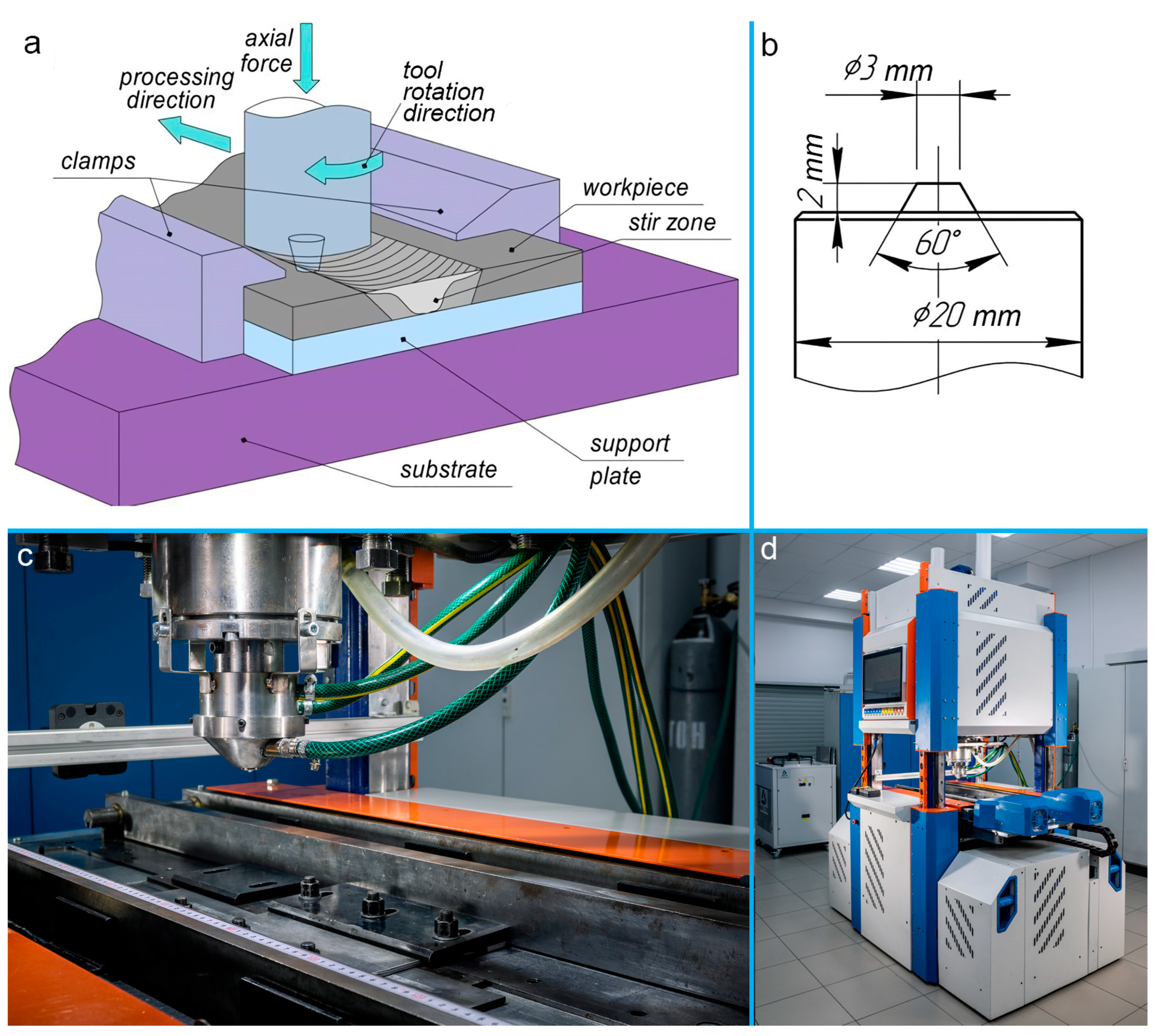
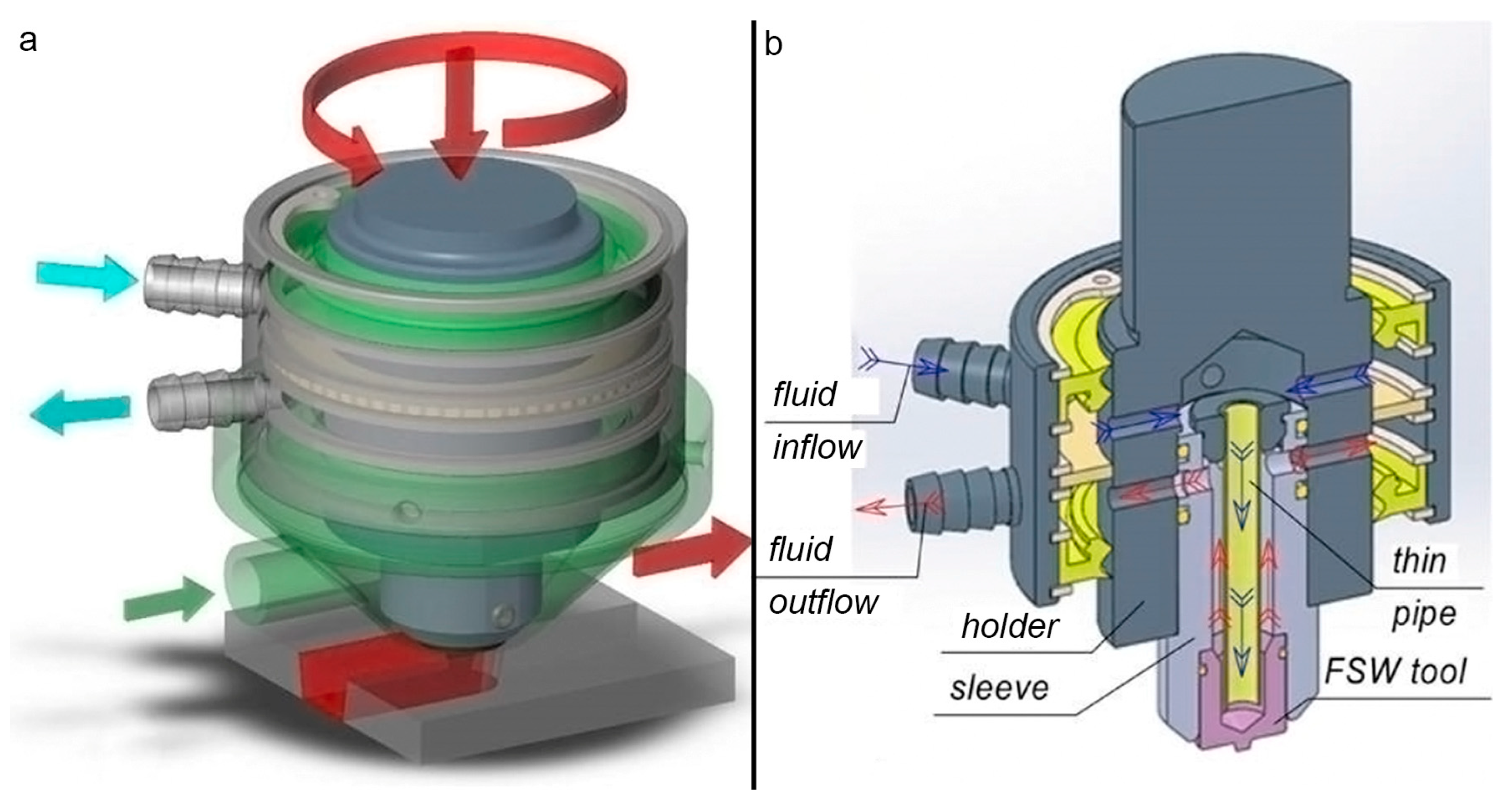
2.1. Materials and Experimental Set-Up
2.2. Investigative Techniques
3. Results and Discussion
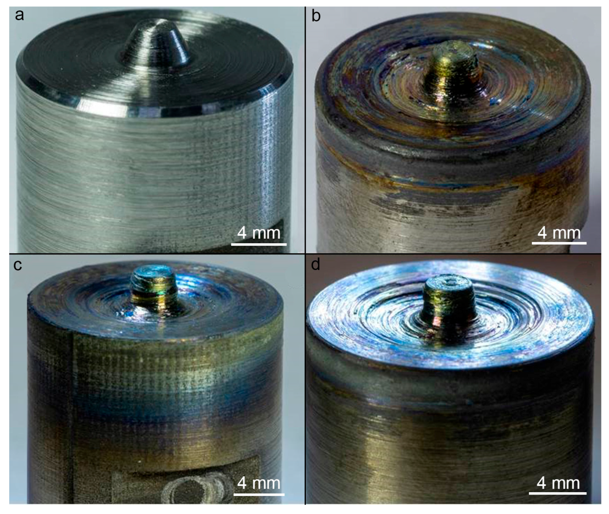
3.1. Wear and Structure of the ZhS32 Ni-Based Superalloy Tool
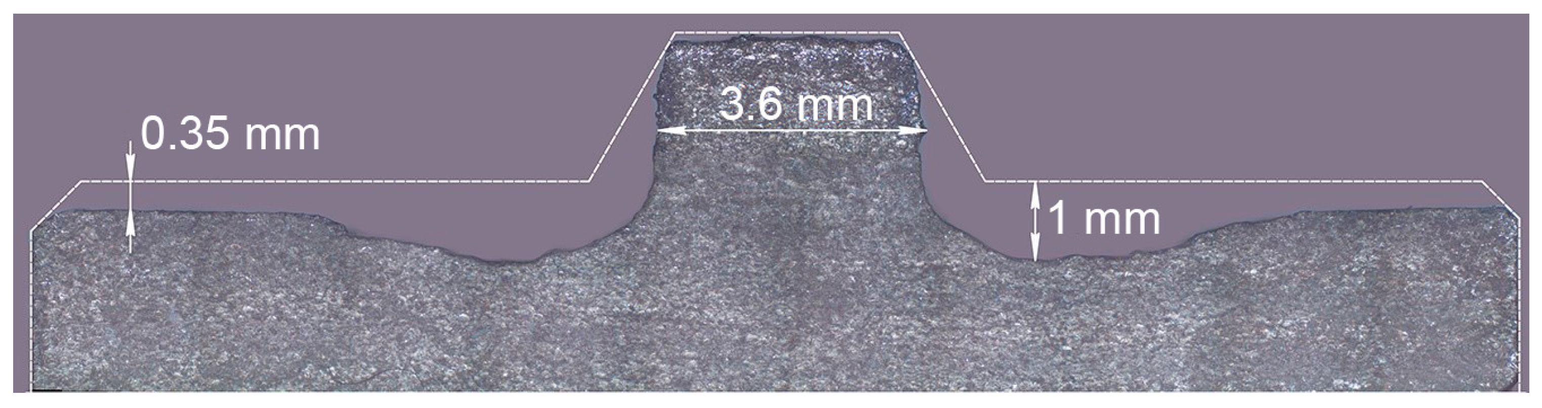
3.2. Quality of Friction Stir Processing by the ZhS32 Tool
3.3. Wear and Structure of the ZhS6U Tool in Friction Stir Processing with Liquid Cooling
3.4. Quality of Friction Stir Processing by the ZhS6U Tool with Liquid Cooling
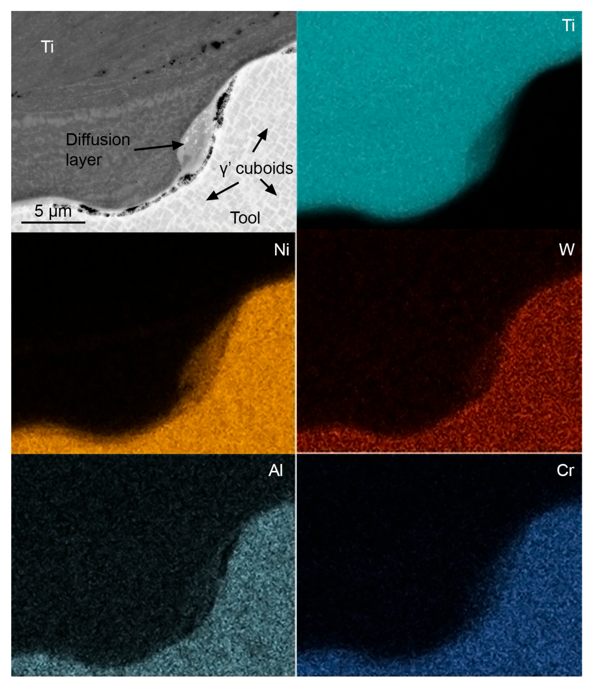
3.5. Tool Wear Mechanism in Friction Stir Processing of Titanium
4. Conclusions
Author Contributions
Funding
Data Availability Statement
Conflicts of Interest
References
- Kato, K.; Sakano, R. Development of spot friction welding and application for automobile body. J. Light Met. Weld. Constr. 2004, 42, 8–13. [Google Scholar]
- Dawes, C.J.; Thomas, W.M. Friction stir welding of aluminium alloys. Bull. TWI 1995, 6, 124–127. [Google Scholar]
- Kolubaev, A.V.; Kolubaev, E.A.; Sizova, O.V.; Zaikina, A.A.; Rubtsov, V.E.; Tarasov, S.Y.; Vasiliev, P.A. General regularities of the microstructure formation during friction stir welding and sliding friction. J. Frict. Wear 2015, 36, 127–131. [Google Scholar] [CrossRef]
- Sizova, O.; Shlyakhova, G.; Kolubaev, A.; Kolubaev, E.A.; Psakhie, S.G.; Rudenskii, G.; Chernyavsky, A.G.; Lopota, V. Microstructure Features of Aluminum Alloys Welded Joint Obtained by Friction Stir Welding. Adv. Mater. Res. 2013, 872, 174–179. [Google Scholar] [CrossRef]
- Peters, M.; Hemptenmacher, J.; Kumpfert, J.; Leyens, C. Structure and Properties of Titanium and Titanium Alloys. In Titanium and Titanium Alloys; Leyens, C., Peters, M., Eds.; Wiley–VCH: Weinheim, Germany, 2005. [Google Scholar]
- Steele, M.C.; Hein, R.A. Superconductivity of Titanium. Phys. Rev. 1953, 92, 243–247. [Google Scholar] [CrossRef]
- Wang, J.; Su, J.; Mishra, R.S.; Xu, R.; Baumann, J.A. Tool wear mechanisms in friction stir welding of Ti–6Al–4V alloy. Wear 2014, 321, 25–32. [Google Scholar] [CrossRef]
- Mishra, R.S.; Ma, Z.Y. Friction stir welding and processing. Mater. Sci. Eng. R 2005, 50, 1–78. [Google Scholar] [CrossRef]
- Nandan, R.; Debroy, T.; Bhadeshia, H. Recent advances in friction-stir welding—Process, weldment structure and properties. Prog. Mater. Sci. 2008, 53, 980–1023. [Google Scholar] [CrossRef] [Green Version]
- Farias, A.; Batalha, G.F.; Prados, E.F.; Magnabosco, R.; Delijaicov, S. Tool wear evaluations in friction stir processing of commercial titanium Ti–6Al–4V. Wear 2013, 302, 1327–1333. [Google Scholar] [CrossRef]
- Liu, H.; Zhou, L.; Liu, Q. Microstructural evolution mechanism of hydrogenated Ti–6Al–4V in the friction stir welding and post-weld dehydrogenation process. Scr. Mater. 2009, 61, 1008–1011. [Google Scholar] [CrossRef]
- Zhou, L.; Liu, H.J. Effect of 0.3 wt.% hydrogen addition on microstructural evolution of Ti–6Al–4V alloy in the friction stir welding and post-weld dehydrogenation process. Mater. Charact. 2011, 62, 1036–1041. [Google Scholar] [CrossRef]
- Wu, L.; Xue, P.; Xiao, B.; Ma, Z. Achieving superior low-temperature superplasticity for lamellar microstructure in nugget of a friction stir welded Ti-6Al-4V joint. Scr. Mater. 2016, 122, 26–30. [Google Scholar] [CrossRef]
- Li, B.; Shen, Y.; Hu, W.; Luo, L. Surface modification of Ti–6Al–4V alloy via friction-stir processing: Microstructure evolution and dry sliding wear performance. Surf. Coat. Technol. 2014, 239, 160–170. [Google Scholar] [CrossRef]
- Pilchak, A.L.; Tang, W.; Sahiner, H.; Reynolds, A.P.; Williams, J.C. Microstructure Evolution during Friction Stir Welding of Mill-Annealed Ti–6Al–4V. Met. Mater. Trans. A 2010, 42, 745–762. [Google Scholar] [CrossRef]
- Wang, J.; Su, J.; Mishra, R.S.; Xu, R.; Baumann, J.A. A Preliminary Study of Deformation Behavior of Friction Stir Welded Ti-6Al-4V. J. Mater. Eng. Perform. 2014, 23, 3027–3033. [Google Scholar] [CrossRef]
- Lippold, J.C.; Livingston, J.J. Microstructure Evolution During Friction Stir Processing and Hot Torsion Simulation of Ti–6Al–4V. Met. Mater. Trans. A 2013, 44, 3815–3825. [Google Scholar] [CrossRef]
- Fall, A.; Fesharaki, M.H.; Khodabandeh, A.R.; Jahazi, M. Tool Wear Characteristics and Effect on Microstructure in Ti–6Al–4V Friction Stir Welded Joints. Metals 2016, 6, 275. [Google Scholar] [CrossRef] [Green Version]
- Rai, R.; De, A.; Bhadeshia, H.K.D.H.; DebRoy, T. Review: Friction stir welding tools. Sci. Technol. Weld. Join. 2011, 16, 325–342. [Google Scholar] [CrossRef]
- Su, Y.; Li, W.; Gao, F.; Vairis, A. Effect of FSW process on anisotropic of titanium alloy T-joint. Mater. Manuf. Process. 2021, 37, 25–33. [Google Scholar] [CrossRef]
- Edwards, P.D.; Ramulu, M. Comparative study of fatigue and fracture in friction stir and electron beam welds of 24 mm thick titanium alloy Ti-6Al-4 V. Fatigue Fract. Eng. Mater. Struct. 2016, 39, 1226–1240. [Google Scholar] [CrossRef]
- Muzvidziwa, M.; Okazaki, M.; Suzuki, K.; Hirano, S. Role of microstructure on the fatigue crack propagation behavior of a friction stir welded Ti–6Al–4V. Mater. Sci. Eng. A 2015, 652, 59–68. [Google Scholar] [CrossRef]
- Yoon, S.; Ueji, R.; Fujii, H. Effect of initial microstructure on Ti–6Al–4V joint by friction stir welding. Mater. Des. 2015, 88, 1269–1276. [Google Scholar] [CrossRef] [Green Version]
- Sato, Y.S.; Susukida, S.; Kokawa, H.; Omori, T.; Ishida, K.; Imano, S.; Park, S.H.C.; Sugimoto, I.; Hirano, S. Wear of cobalt–based alloy tool during friction stir welding of Ti–6Al–4V alloy. In Proceedings of the 11th International Symposium on FrictionStir Welding, Cambridge, UK, 17–19 May 2016. [Google Scholar]
- Mironov, S.; Zhang, Y.; Sato, Y.S.; Kokawa, H. Crystallography of transformed b microstructure in friction stir welded Ti–6Al–4V alloy. Scripta Mater. 2008, 59, 511–514. [Google Scholar] [CrossRef]
- Mironov, S.; Sato, Y.S.; Kokawa, H. Grain Structure Evolution during Friction-Stir Welding. Phys. Mesomech. 2020, 23, 21–31. [Google Scholar] [CrossRef]
- Zhang, Y.; Sato, Y.S.; Kokawa, H.; Park, S.H.C.; Hirano, S. Microstructural characteristics and mechanical properties of Ti–6Al–4V friction stir welds. Mater. Sci. Eng. A 2008, 485, 448–455. [Google Scholar] [CrossRef]
- Mironov, S.; Sato, Y.; Kokawa, H. Friction-stir welding and processing of Ti–6Al–4V titanium alloy: A review. J. Mater. Sci. Technol. 2018, 34, 58–72. [Google Scholar] [CrossRef]
- Wu, L.H.; Wang, D.; Xiao, B.L.; Ma, Z.Y. Tool wear and its effect on microstructure and properties of friction stir processed Ti–6Al–4V. Mater. Chem. Phys. 2014, 146, 512–522. [Google Scholar] [CrossRef]
- Zhang, Y.; Sato, Y.S.; Kokawa, H.; Park, S.H.C.; Hirano, S. Stir zone microstructure of commercial purity titanium friction stir welded using pcBN tool. Mater. Sci. Eng. A 2008, 488, 25–30. [Google Scholar] [CrossRef]
- Kablov, E.N.; Petrushin, N.V.; Parfenovich, P.I. Design of Castable Refractory Nickel Alloys with Polycrystalline Structure. Met. Sci. Heat Treat. 2018, 60, 106–114. [Google Scholar] [CrossRef]
- Costa, A.M.S.; Oliveira, J.P.; Pereira, V.F.; Nunes, C.A.; Ramirez, A.J.; Tschiptschin, A.P. Ni-based Mar-M247 superalloy as a friction stir processing tool. J. Mater. Process. Technol. 2018, 262, 605–614. [Google Scholar] [CrossRef]
- Amirov, A.I.; Eliseev, A.A.; Rubtsov, V.E.; Utyaganova, V.R. Butt friction stir welding of commercially pure titanium by the tool from a heat-resistant nickel alloy. AIP Conf. Proc. 2019, 2167, 020016. [Google Scholar] [CrossRef]
- Amirov, A.; Eliseev, A.; Kolubaev, E.; Filippov, A.; Rubtsov, V. Wear of ZhS6U Nickel Superalloy Tool in Friction Stir Processing on Commercially Pure Titanium. Metals 2020, 10, 799. [Google Scholar] [CrossRef]
- Mironov, S.Y. Temperature Distribution within the Friction Stir Welding Tool. Phys. Mesomech. 2023, 26, 33–38. [Google Scholar] [CrossRef]
- Hasieber, M.; Kranz, M.; Löhn, T.; Grätzel, M.; Zemlicka, A.; Bergmann, J.P. Effect of friction stir welding tool hardness on wear behaviour in friction stir welding of AA-6060 T66. Proc. Inst. Mech. Eng. Part L J. Mater. Des. Appl. 2022, 236, 1333–1345. [Google Scholar] [CrossRef]
- Tarasov, S.; Amirov, A.; Chumaevskiy, A.; Savchenko, N.; Rubtsov, V.E.; Ivanov, A.; Moskvichev, E.; Kolubaev, E. Friction Stir Welding of Ti-6Al-4V Using a Liquid-Cooled Nickel Superalloy Tool. Technologies 2022, 10, 118. [Google Scholar] [CrossRef]
- Frigaard, Ø.; Grong, Ø.; Midling, O.T. A process model for friction stir welding of age hardening aluminum alloys. Metall. Mater. Trans. A 2001, 32, 1189–1200. [Google Scholar] [CrossRef]
- Kim, Y.; Fujii, H.; Tsumura, T.; Komazaki, T.; Nakata, K. Three defect types in friction stir welding of aluminum die casting alloy. Mater. Sci. Eng. A 2005, 415, 250–254. [Google Scholar] [CrossRef]
- Sadoun, A.; Wagih, A.; Fathy, A.; Essa, A. Effect of tool pin side area ratio on temperature distribution in friction stir welding. Results Phys. 2019, 15, 102814. [Google Scholar] [CrossRef]
- Tarasov, S.Y.; Filippov, A.; Kolubaev, E.; Kalashnikova, T. Adhesion transfer in sliding a steel ball against an aluminum alloy. Tribol. Int. 2017, 115, 191–198. [Google Scholar] [CrossRef]
- Tarasov, S.Y.; Kalashnikova, T.A.; Kalashnikov, K.N.; Rubtsov, V.E.; Eliseev, A.A.; Kolubaev, E.A. Diffusion-controlled wear of steel friction stir welding tools used on aluminum alloys. AIP Conf. Proc. 2015, 1683, 020228. [Google Scholar] [CrossRef]


| Fe | Nb | Re | Cr | Co | W | Ni | Al | Mo | S |
|---|---|---|---|---|---|---|---|---|---|
| ≤0.5 | 1.4–1.8 | 3.6–4.3 | 4.5–5.3 | 9–9.5 | 8.1–8.9 | 56.88–62.98 | 5.7–6.2 | 0.9–1.3 | ≤0.005 |
| Ce | Si | Mn | P | C | Ta | Cu | B | V | Y |
| ≤0.025 | ≤0.2 | ≤0.3 | ≤0.01 | 0.12–0.17 | 3.7–4.4 | ≤0.03 | ≤0.02 | ≤0.15 | ≤0.005 |
| Fe | Nb | Ti | Cr | Co | W | Ni | Al | Mo | S |
|---|---|---|---|---|---|---|---|---|---|
| ≤1 | 0.8–1.2 | 2–2.9 | 8–9.5 | 9–10.5 | 9.5–11 | 54.3–62.7 | 5.1–6 | 1.2–2.4 | ≤0.01 |
| Ce | Si | Mn | P | C | Zr | Bi | B | Pb | Y |
| ≤0.02 | ≤0.4 | ≤0.4 | ≤0.015 | 0.13–0.2 | ≤0.04 | ≤0.0005 | ≤0.035 | ≤0.01 | ≤0.01 |
| Fe | C | Si | N | Ti | O | H | Impurity |
|---|---|---|---|---|---|---|---|
| ≤0.25 | ≤0.07 | ≤0.1 | ≤0.04 | 99.24–99.7 | ≤0.2 | ≤0.01 | balance 0.3 |
| Parameters | Base Material | Tool Material |
|---|---|---|
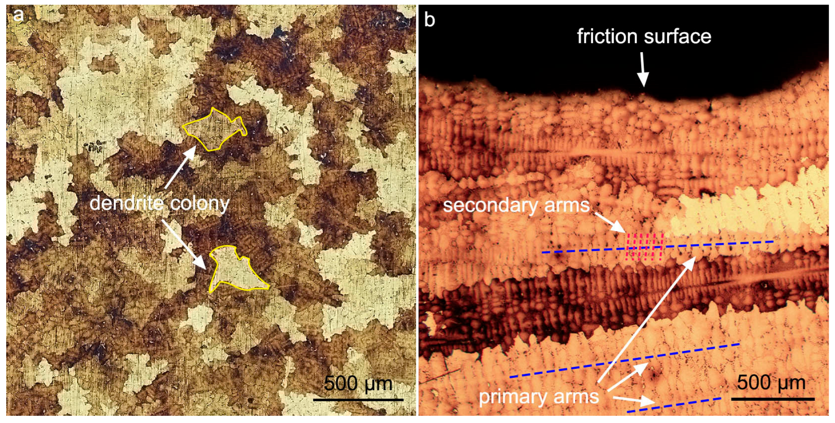
| Size of dendritic colonies, mm | 0.36 ± 0.09 | 1.36 ± 0.66 |
| Primary arm spacing, µm | 231 ± 33 | 316 ± 80 |
| Secondary arm spacing, µm | 26 ± 3 | 39 ± 5 |
| Parameters | Base Material | Tool Material |
|---|---|---|
| Size of dendritic colonies, mm | 0.27 ± 0.09 | 1.3 ± 0.3 |
| Primary arm spacing, µm | 66 ± 5 | 229 ± 42 |
| Secondary arm spacing, µm | 14 ± 1 | 48 ± 7 |
Disclaimer/Publisher’s Note: The statements, opinions and data contained in all publications are solely those of the individual author(s) and contributor(s) and not of MDPI and/or the editor(s). MDPI and/or the editor(s) disclaim responsibility for any injury to people or property resulting from any ideas, methods, instructions or products referred to in the content. |
© 2023 by the authors. Licensee MDPI, Basel, Switzerland. This article is an open access article distributed under the terms and conditions of the Creative Commons Attribution (CC BY) license (https://creativecommons.org/licenses/by/4.0/).
Share and Cite
Amirov, A.; Eliseev, A.; Beloborodov, V. Wear of Ni-Based Superalloy Tools in Friction Stir Processing of Commercially Pure Titanium. Lubricants 2023, 11, 307. https://doi.org/10.3390/lubricants11070307
Amirov A, Eliseev A, Beloborodov V. Wear of Ni-Based Superalloy Tools in Friction Stir Processing of Commercially Pure Titanium. Lubricants. 2023; 11(7):307. https://doi.org/10.3390/lubricants11070307
Chicago/Turabian StyleAmirov, Alihan, Alexander Eliseev, and Vladimir Beloborodov. 2023. "Wear of Ni-Based Superalloy Tools in Friction Stir Processing of Commercially Pure Titanium" Lubricants 11, no. 7: 307. https://doi.org/10.3390/lubricants11070307