High-Temperature Superlubricity Performance of h-BN Coating on the Textured Inconel X750 Alloy


Key Laboratory of Education Ministry for Modern Design and Rotor-Bearing System, Xi’an Jiaotong University, Xi’an 710049, China
Lubricants 2023, 11(6), 258; https://doi.org/10.3390/lubricants11060258
Submission received: 31 March 2023
/
Revised: 3 June 2023
/
Accepted: 9 June 2023
/
Published: 10 June 2023
(This article belongs to the Special Issue Green Tribology: New Insights toward a Sustainable World 2023)
Abstract
:The high-temperature superlubricity performances of h-BN coatings on the nontextured and textured surface of an Inconel X750 alloy is reported in the present paper. The hardness and bond strength of the h-BN coating and alloy were investigated. The tribological properties of the X750 alloy and coatings on the X750 alloy substrate were investigated at different temperatures. The surface texture was manufactured on the surface of the X750 alloy, and then coatings were deposited on the textured surface to reduce the cracking of the coating and enhance the stability of the antifriction behaviors of the h-BN coatings. The tribotest results showed that the texture is helpful to enhance the interface thermal compatibility of the coating and substrate and store the wear debris generated during sliding. Therefore, a stable superlubricity was achieved at high temperatures, and a super low friction mechanism is also discussed.
1. Introduction
Many machine parts, such as gas foil bearings, work under high-temperature conditions. Some gas foil bearings are made with an Inconel X-750 alloy. An X-750 alloy exhibits excellent mechanical properties and hot corrosion resistance [1]. In industry applications, there is a need for lubrication materials with low friction and a high wear rate at high temperatures [2,3,4,5]. Liquid lubricants may lose their lubricating function at high temperatures [6]. Solid lubricants are widely used at high temperatures and in ambient conditions. However, most solid lubricants (e.g., graphite and DLC films) may fail at elevated temperatures [7].
The h-BN with a lamellar crystal structure is applied in many fields because of its high thermal conductivity and excellent chemical stability. The h-BN can be used as a lubricant, and it even has good lubricity at high temperatures [8,9]. Chen et al. prepared SiC/h-BN composites and investigated the tribological properties of composites from room temperature (RT) to 900 °C [10]. The composite exhibited excellent lubricating performances with 0.30 of the CoF (coefficient of friction) above 800 °C [11]. Lu et al. prepared Ni60/h-BN coatings on 304 steel and studied the friction of the coatings [12]. The CoF and wear rates of the h-BN/Ag in Ni-based composites decreased as the temperature increased from RT to 600 °C [13]. The Ni60/h-BN coatings on the TC4 alloy were prepared. The TiB2 and the metal oxides were synthesized during sliding, indicating good high-temperature lubrication [14]. Yuan et al. deposited h-BN coatings on a Ti alloy, and the CoF was reduced from 0.72 to 0.35 [15]. Zhao et al. manufactured the composite (Ni60/nano-Cu/h-BN) with MoO3 on Q235 steel and found that a tribochemical film of CuMoO4 was formed during friction. The transfer film is helpful when improving high-temperature antifriction behaviors [16]. Cao et al. designed a CuSn10 layer of a h-BN/graphite coating on engine bearing. The CoFs fell by 225.00% at RT and 857.14% at 200 °C due to the transfer film [17]. Raadnui et al. produced 316L steel composites with h-BN and MoS2. The tribological properties depended on the friction conditions and the formation of tribofilms [18]. The h-BN is usually used as a solid lubricant component in the composite and is used for high-temperature tribological applications [19,20,21,22,23]. In previous research, h-BN coatings were manufactured on steel, and the results showed that the coatings were helpful at enhancing the tribological properties of steel at high temperatures [8]. However, it was shown that the steel was easily oxidized under high temperatures [24,25,26]. In this paper, h-BN coatings were prepared on an Inconel X-750 alloy by using the radio frequency magnetron sputtering method to avoid high-temperature oxidation, and the friction behaviors from room temperature to 800 °C was investigated. The objective of this study was to investigate the tribological properties of the substrate of an X750 alloy at high temperatures while the surface texture affects the high-temperature tribology of the coatings.
2. Experiments
The h-BN coatings were prepared on Inconel X-750 alloy discs. The experimental details can be found in reference [8]. The disc was polished with sandpaper. The discs were ultrasonically cleaned. The h-BN coatings were deposited on the X750 alloy discs. A ZrO2 ball was used as the friction pair. The stages included heating, insulation and holding. The whole heating process could be controlled by using suitable parameters such as the heating rate, heating temperature and holding time. The maximum pressure was about 0.6 GPa under a load of 2 N. The testing load was lower than the load corresponding to the actual operating conditions of the bearing, but the contact pressure was not very low. The tribotest temperatures were room temperature, 500 °C, 600 °C, 700 °C and 800 °C.
Surface textures are helpful at reducing the actual contact area and storing debris, reducing friction and extending the wear life of the coating. The surface texture was prepared before the deposition of the coating. The texture was first manufactured and then the h-BN coatings were sputtered on the textured surface of the X750 alloy. The surface texture was prepared by a QC-F20 laser marking machine from Xi’an Qinchuang Company (Xi’an, China). The equipment parameters were as follows: The voltage was 220 V, power was 20 W, laser wavelength was 1064 nm and pulse width was 1.0 ms. The shape of the surface texture was a circular concave texture. The radius of the circle was 200 μm, the spacing between the centers of the circle hole was 600 μm and the surface density was 35%. To control the processing depth of the texture, the power was 16 W and the scanning speed was 1000 mm/s. The parameters of the texture were selected according to the previous paper [8].
The microstructure of the h-BN coatings was studied by using X-ray diffraction (XRD, D8-Advance, Bruker, Saarbrücken, Germany). A scanning electron microscope (SEM, MALA3 LMH) and Laser scanning confocal microscopy (LSCM, OLS4000) were used to measure the parameters of the worn surface, and then the specific wear rate was calculated.
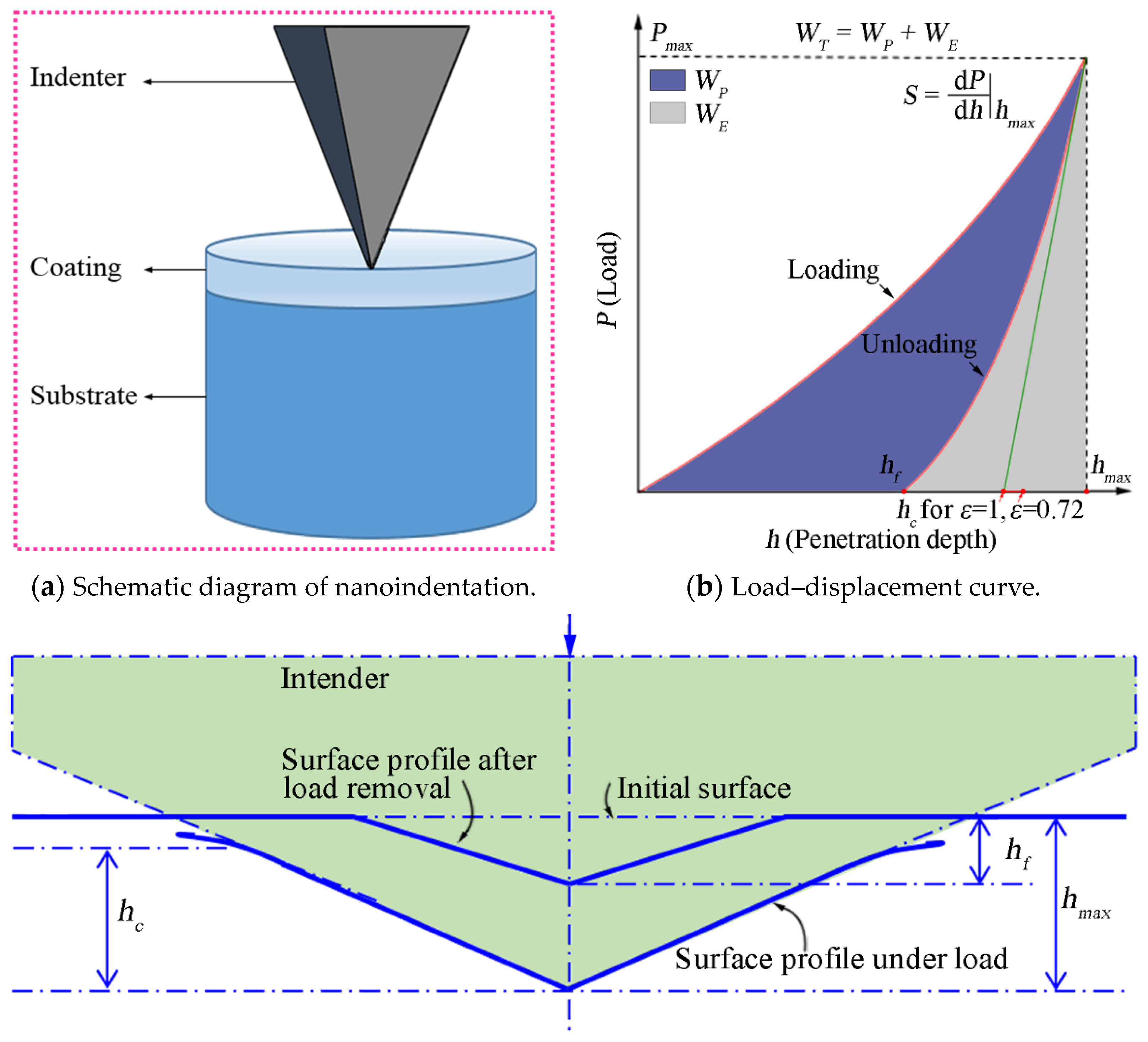
The hardness of the coatings was measured with a nanoindentation tester (Ti950, Hysitron, Eden Prairie, Hennepin, MI, USA). The principle is the load–displacement curve of the indenter during and outside of the process, and the hardness and elastic modulus of the material were obtained.
Figure 1 shows the schematic and schematic diagram of the nanoindentation test, as well as the load–displacement curve of a typical loading–unloading process. The details are provided to show the nanoindentation procedure of the coating and X750 alloy.
The surface morphology of the coatings was observed with anatomic force microscope (AFM; Innova; Bruker; Saarbrücken, Germany). The microstructure of the h-BN coatings was characterized by Fourier Transform Infrared Spectroscopy (FTIR). A Bruker Tensor 27 spectrometer was used to measure the microstructure of the coatings in a wave number range of 400–4000 cm−1 by using the KBr pellet method.
3. Results and Discussion
3.1. Composition of Inconel X750 Alloy
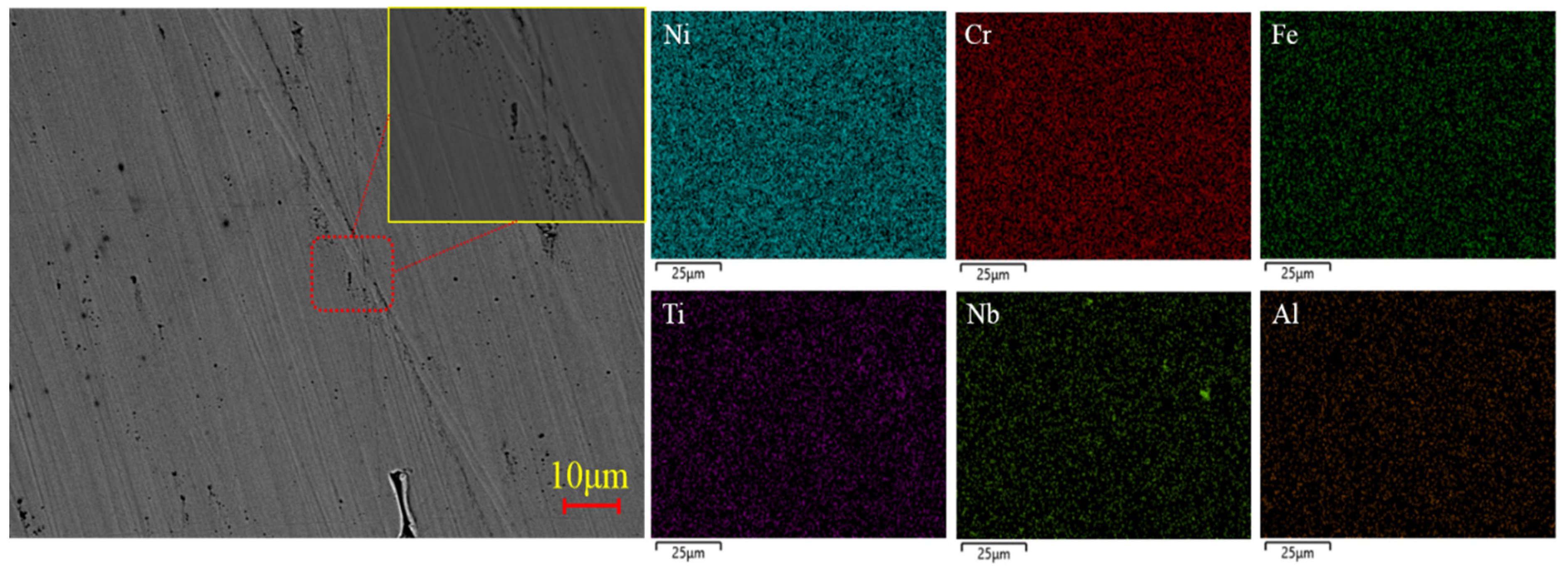
An Inconel X750 nickel-based alloy was used as the substrate, and it has a high strength and high oxidation resistance. The Inconel X750 alloy is used to manufacture high-temperature machine parts such as the structural parts of aircraft engines, high-temperature springs, turbine blades, etc. It is also used to manufacture the wave foil and top foil of gas dynamic pressure foil bearings due to its high temperature resistance; however, the hardness and wear resistance of the alloy is low. Figure 2 shows SEM images and the elemental distribution of the X750 alloy. It was found from the SEM images that the surface of the alloy was flat and without cracks. However, there were a number of pores generated in the process of manufacturing and scratches on the surface left by the polishing sandpaper during grinding and polishing. There were elements including Ni, Cr, Fe, Ti, Nb and Al from the EDS of the surface. It was shown that all the elements were uniformly distributed on the surface, which is helpful to ensure the good mechanical properties of the alloy. Table 1 shows the elemental composition and proportion of the alloy. The weight percentage of each element was within the suitable ranges, and there were no defects of the material and elemental compositions in the alloy.
The Vickers hardness tester was used to measure the hardness of the X750 alloy. Six points at different positions on the disk were selected for measurement. Table 2 shows the hardness of the Inconel X750 alloy. The average hardness of the Inconel X750 alloy was 217.7 HV.
3.2. Structural Characterization and Mechanical Properties of h-BN Coatings on X750 Alloy
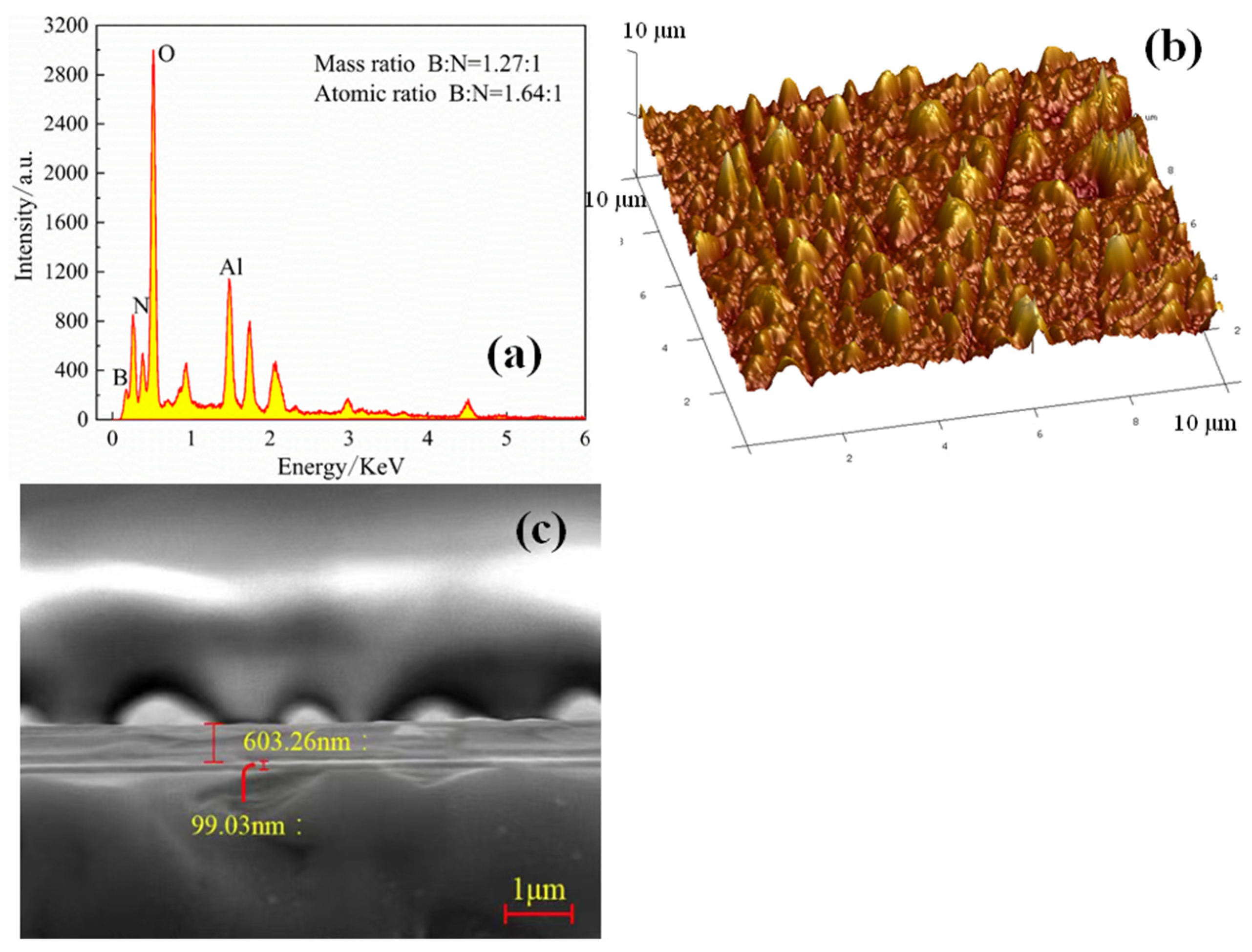
Figure 3 shows the elements and surface roughness of the h-BN coatings. It was found that the h-BN coating had a dense structure. The mass ratio of boron and nitrogen in the h-BN coatings was 1.27:1 and the atomic ratio was 1.64:1. Al and O elements were found in a spectrum because the material of the sandpaper that was used during grinding and polishing was Al2O3. Atomic force microscopy (AFM) was used to measure the surface roughness of the h-BN coating. The Ra of surface roughness was 9.8 nm and the Rq value was 13.2 nm. The coating’s thickness was about 600 nm.
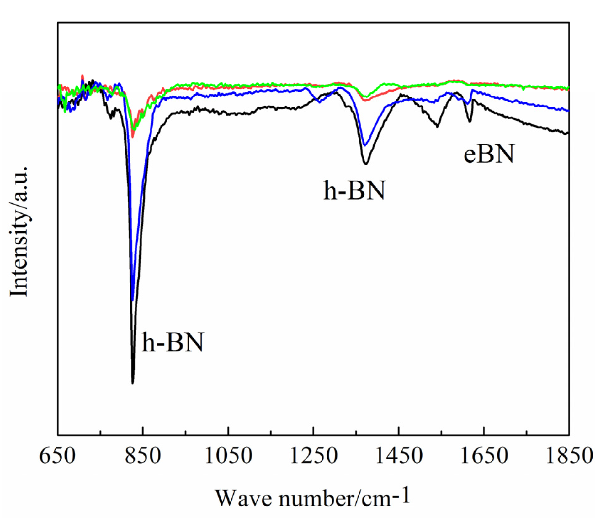
The microstructure of the h-BN coatings was measured with a Fourier transform infrared spectrum (FTIR) to confirm the composition of the h-BN coatings prepared by magnetron sputtering. Four different positions of the h-BN coatings were selected for measuring. Figure 4 shows the FTIR curves of the h-BN coatings. The peaks around 780 cm−1 and 1360 cm−1 of the wave number represent h-BN [27]. The peaks around 960 cm−1, 1250 cm−1, 1450 cm−1 and 1600 cm−1 represent e-BN. However, the peaks at 820 cm−1 and 1378 cm−1 are the characteristic peaks of h-BN, while the peaks at 1620 cm−1 are e-BN. The intensity of the peaks represents the content of the component. It was shown that the coatings included lots of h-BN and a small amount of e-BN. There was a phase transition in the h-BN coating due to the bombardment of ions during the magnetron sputtering.
3.3. Mechanical Properties of Coatings
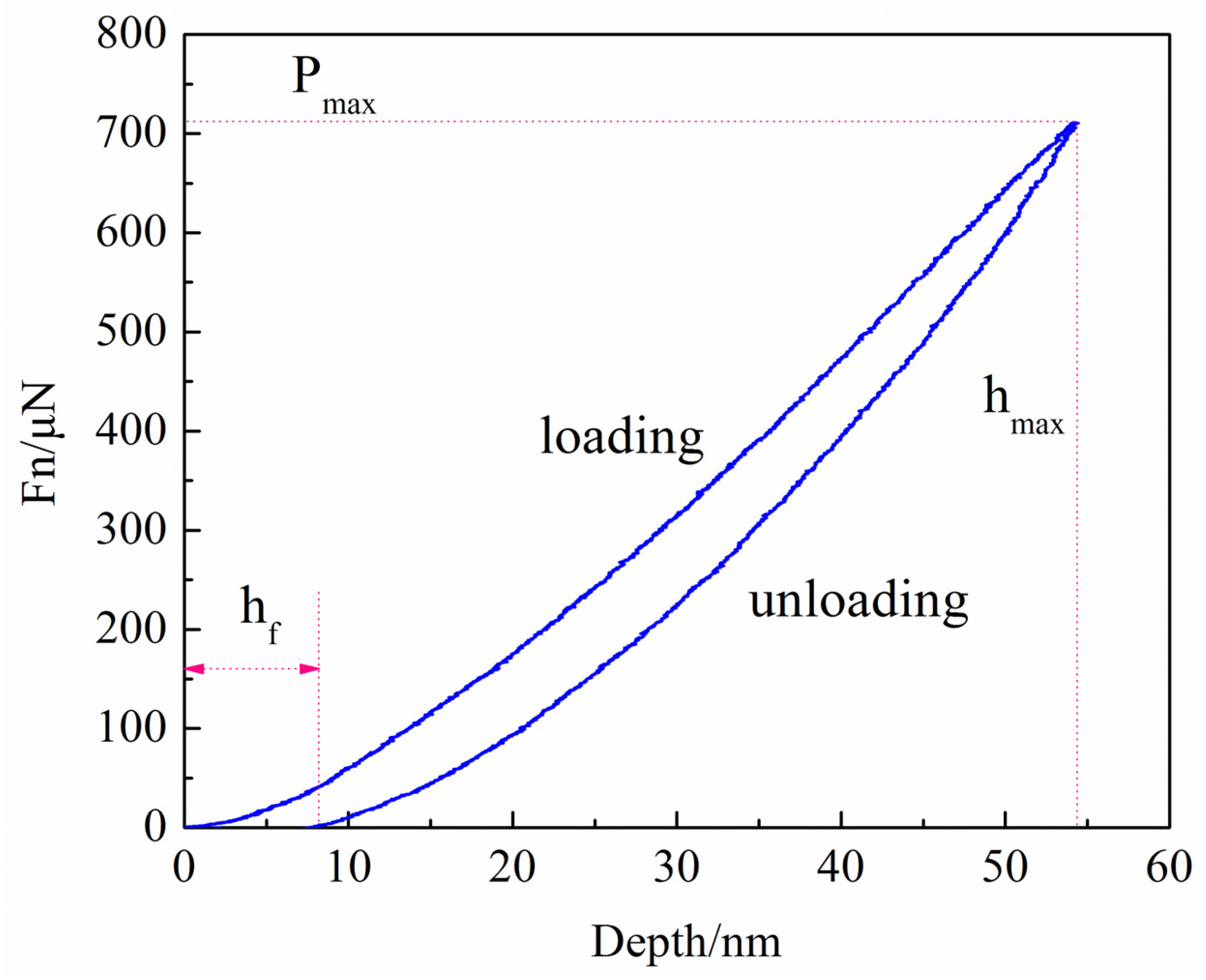
A nanoindentation test was performed on the coatings. Figure 5 shows the loading–unloading curve of the h-BN coatings. The maximum pressing depth was 54.32 nm, and the corresponding peak load was 710.7 μN. The residual coating depth was 7.56 nm. The elastic recovery ability can be described by the elastic recovery rate, which reached 86.08% and was beneficial for the antifriction performance of the coatings. The hardness of the h-BN was 3.39 GPa, and the elastic modulus was 46.87 GPa. The H/E of the coatings was 0.072. The hardness of the coatings was high due to a small amount of e-BN, which was considered a fullerene-like structure with a multi atomic unit cell. The existence of the e-BN phase is helpful to improve the hardness of the h-BN coatings.
3.4. Bond Strength of h-BN Coatings
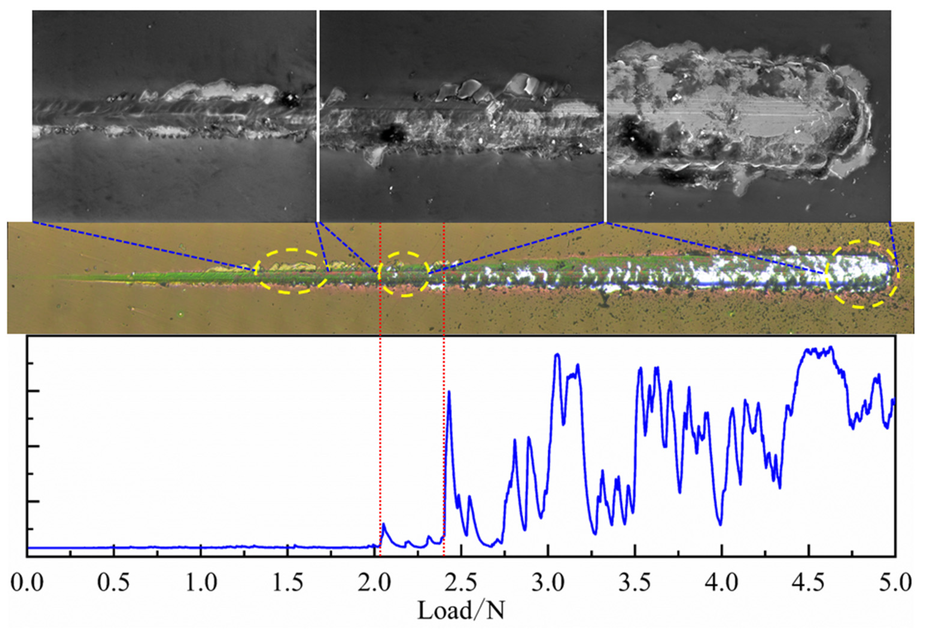
The micron scratch test was carried out on the coatings at a constant velocity to measure the binding property of the h-BN coating on the X750 alloy. Figure 6 shows SEM images and the acoustic emission signal of the scratches. It was shown that the emission signals began to fluctuate at a load of 2.03 N, which was the critical load. This critical load was selected as the criterion used to determine the bond strength of the coatings to the substrate. The critical load of the coatings was determined by the fluctuation in the acoustic emission signal and microscopic observation.
It was found from the scratch surface topography that at the initial loading stage, the indenter scratching the coating part could not cause the separation and spalling of the coatings and the substrate. The scratch width gradually increased with the increase in the load. It was found from the acoustic emission (AE) signal that the scratch edge of the coatings began to spall, but the coatings in the indentation were still good on the surface of the substrate. When the load reached 2.4 N, the acoustic emission signal fluctuated obviously. It was seen from the SEM images that the coatings at the scratch boundary began to flake off from 2.03 N to 2.4 N, and the coatings in the middle of the scratch appeared to have an obvious tensile crack. This shows that the abrupt change in the AE signal sensitively reflects the morphological changes in the scratched surface of the coatings. When the indenter was drawn to the end point, the coating around the middle and edge of the scratch were basically peeled off, the substrate was obviously scratched and the coating had completely failed.
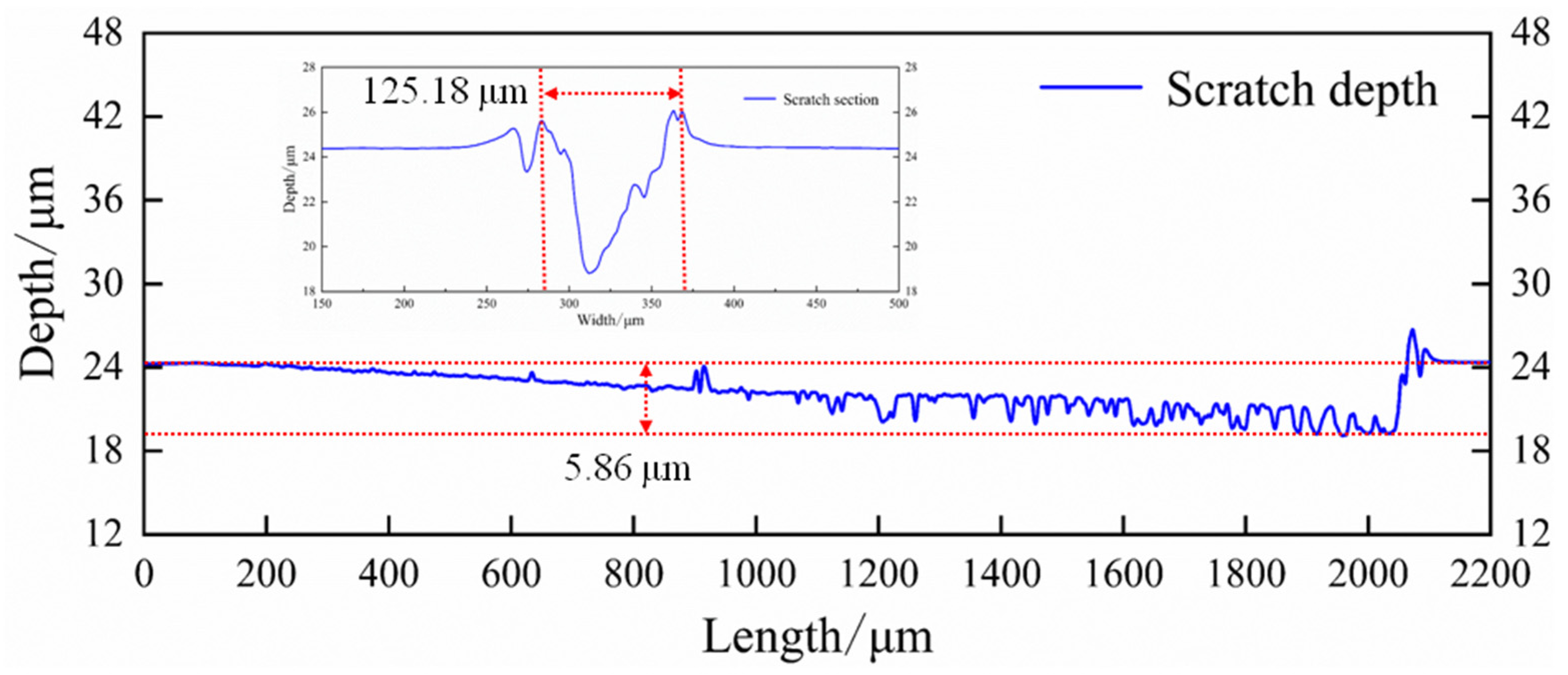
Figure 7 shows the transverse and longitudinal cross-section curves of the scratch of the coatings. It was shown that the depth of the scratch increased, and the final depth of the scratch was 5.86 μm, which indicated that the coatings failed because the thickness of the coating was about 600 nm, which was less than the depth of the scratch. There was a good bonding with the substrate, although the edge coatings were cracked due to the stress. The coatings in the middle part of the scratch were gradually scratched away from the substrate, and there was no sudden fracture stripping phenomenon with the increase in pressure. The final scratch width was about 125.18 μm.
3.5. Tribological Properties of Inconel X750 Alloy
The X750 nickel-based super alloy was used as the substrate for the h-BN coatings; therefore, it is necessary to investigate the tribological properties of the X750 alloy at different temperatures.
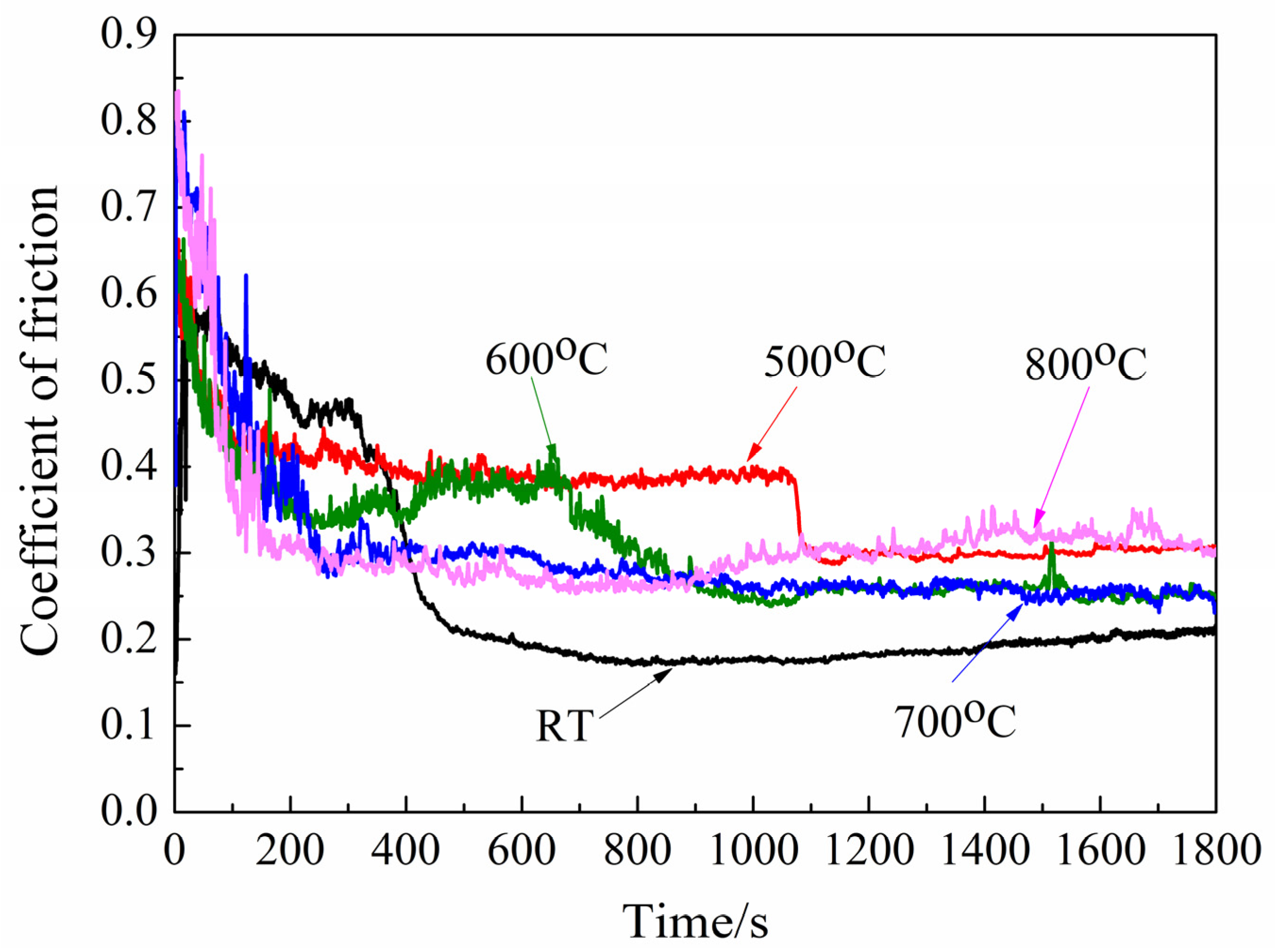
Figure 8 shows the CoF of the Inconel X750 alloy at different temperatures: room temperature (RT), 500 °C, 600 °C, 700 °C and 800 °C. The test time was 30 min. At RT, the initial CoF was 0.589. The CoF decreased to 0.21 and finally to around 0.22 at the stable stage. At 500 °C, the initial CoF was 0.71. The CoF decreased to 0.413 and finally to around 0.3. At 600 °C, the initial CoF was 0.65. The CoF decreased to 0.364 and finally to about 0.25. At 700 °C, the initial CoF was 0.806. The CoF decreased to 0.29, and finally, the CoF was about 0.255. At 800 °C, the initial CoF was 0.835 and then decreased to 0.305 at the stable stage.
According to the CoF curve, the alloy exhibited the lowest CoF at RT. At high temperatures, the CoF became stable around 240 s in the running stage, where by it went from a high initial CoF to a stable value. However, the running time at the stable stage was long compared with the running time for the high-temperature tribotest due to the softening of the alloy at high temperatures.
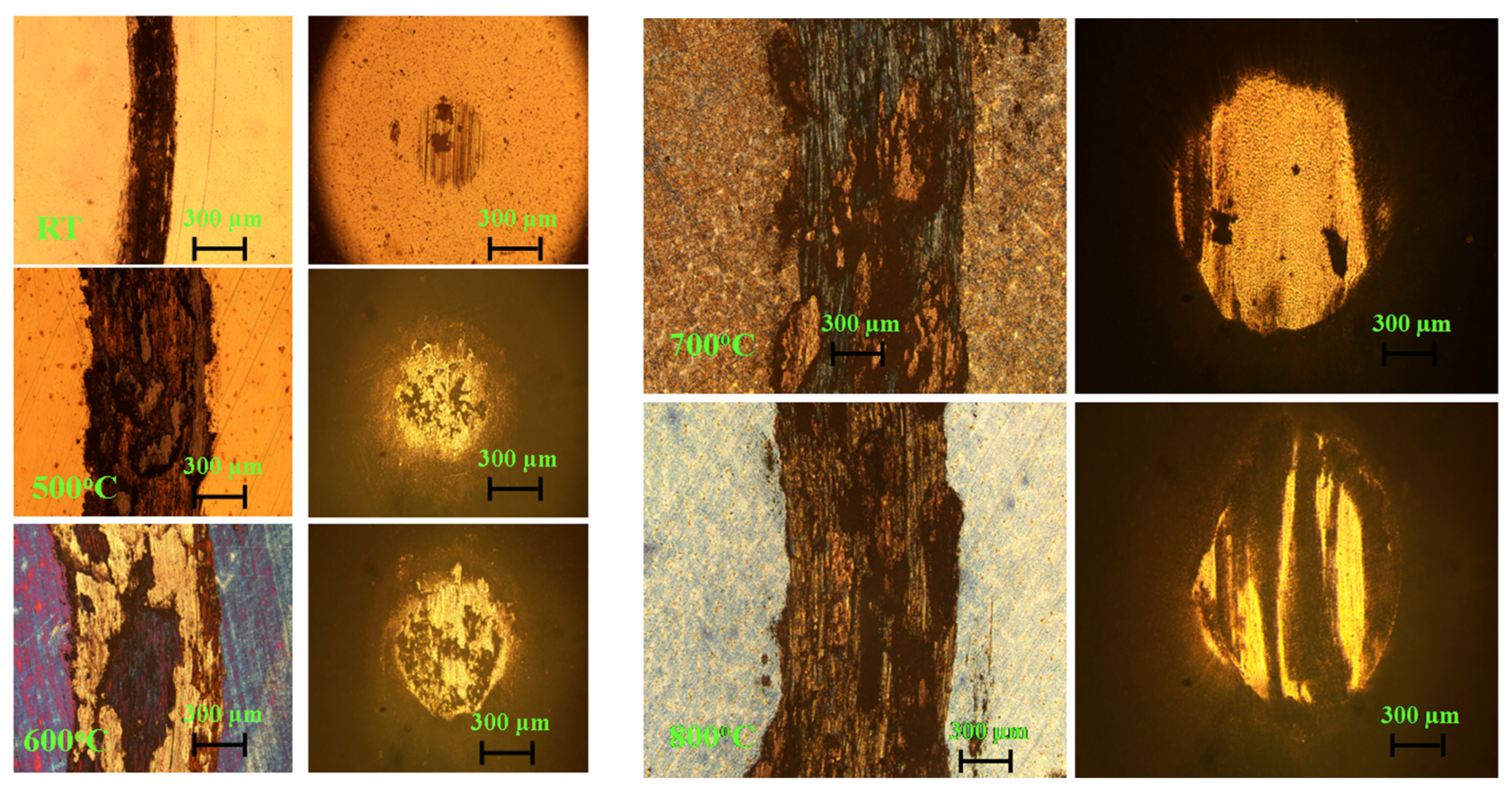
Figure 9 shows the worn surface morphology of the X750 alloy at different temperatures. At RT, the width of the wear scar on the disc was 471.82 μm. There was no deep furrow or bump on the surface of the disc. The worn surface on the ball was small, there were shallow groove marks along the friction direction and the diameter of the wear scar was 370.72 μm. It was shown that the slight wear corresponded to the low friction of the friction pair. At 500 °C, the width of the wear scar on the disc was 1157.45 μm, and the diameter of the wear scar on the ball was 941.66 μm. It was shown that the wear became serious at high temperatures. There was serious adhesive wear on the disc and ball, and an obvious adhesion layer surrounded the ball, as could be seen by the morphology of the abrasion mark. There was a sudden drop in friction at 1070 s at 500 °C. At 600 °C, the widths of the wear scar on the disc and ball became wide and were 1439.22 μm and 1118.22 μm, respectively. At 700 °C and 800 °C, the width of the disc wear marks was similar to those at 500 °C, which were 1064.71 μm and 1082.55 μm, respectively. However, the diameter of the wear scar on the ball increased obviously. The diameters of the wear scar on the ball were 1435.67 μm and 1305.48 μm. The reason is that the difference in hardness between the ceramic ball and X750 alloy was high. With the increase in the temperature, the softening of the X750 alloy became serious at high temperatures. The depth that the silicon carbide ball pressed into the disk was deep under load, which led to a high grinding spot diameter of the ball with the increase in temperature. It was found that there were obvious adhesions of the substrate material at the wear scar of the ball from RT to 800 °C. The material of the wear debris from the disk was transferred to the surface of the ball at the friction interface during sliding. Then, the transferred film was destroyed under the friction force, which resulted in the loss and abrasion of the materials at the friction interface. Adhesive wear was the wear mechanism of the friction pair. There were black materials on the wear scar of the ball, and the material of the disk was transferred to the surface of the ball at the friction interface during sliding. The ZrO2 ball was used as the friction pair, and ZrO2 could not oxidize at the temperatures used during the present experiments.
The layered solid lubrication coating with a low shear strength could separate the friction interface and prevent the bonding of the materials, which resulted in a low CoF because of the interlayer slip of the lubricating materials. Therefore, h-BN with a weak interlayer bonding force was prepared on the surface of the X750 alloy to improve the high-temperature tribological properties of the Inconel X750 alloy.
3.6. Tribological Properties of h-BN Coatings on the Surface of X750 Alloy
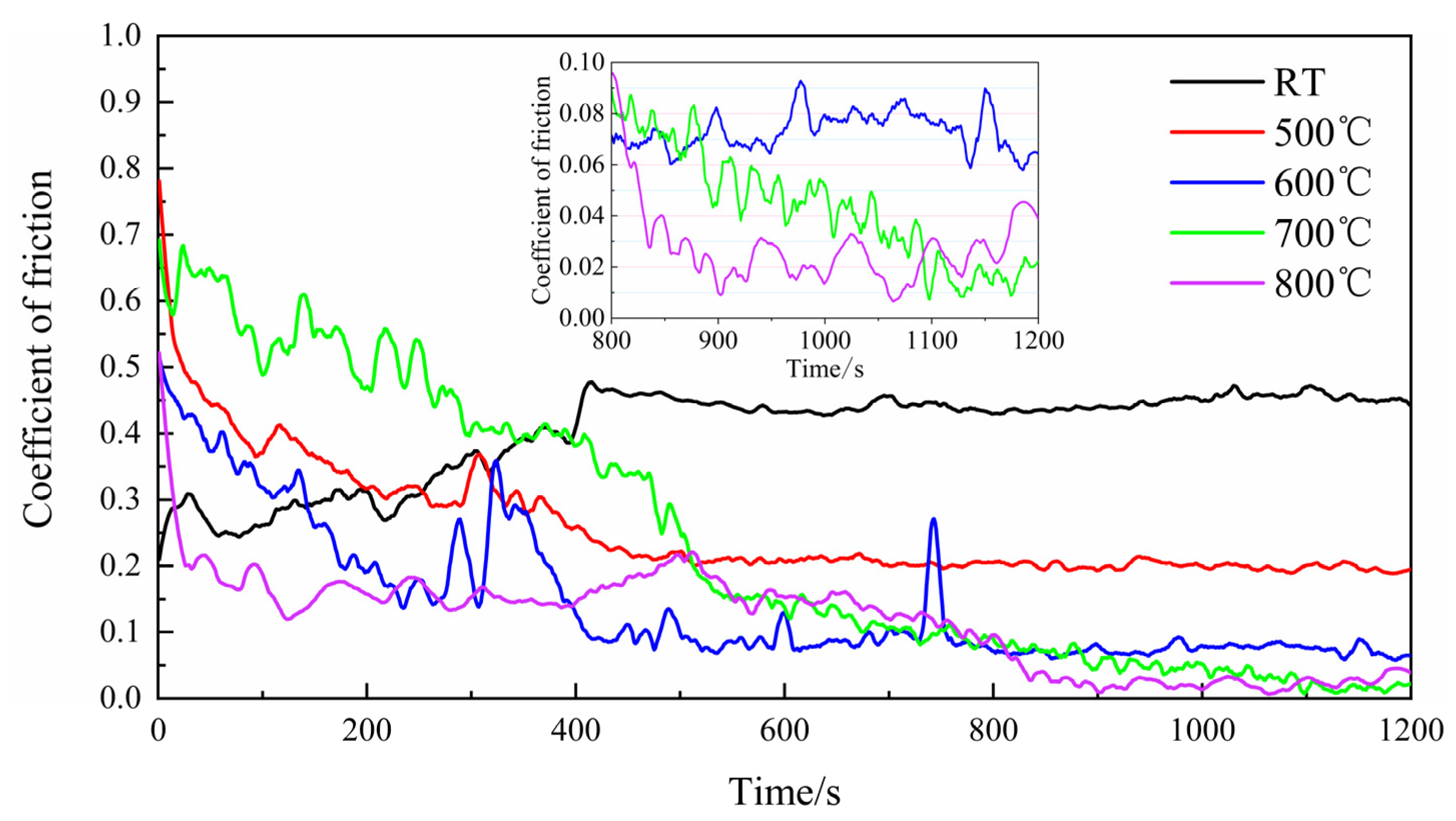
Figure 10 shows the CoF curve of the h-BN coatings at different temperatures. It was shown that the CoF decreased with the increase in temperature. At room temperature, the CoF was high and increased slowly. The initial CoF was about 0.2, and the final CoF reached 0.45, which was larger than that of the X750 alloy. This may have been due to the uniform composition and low hardness of the X750 alloy. The coatings were crushed and broken under load, which resulted in a stable CoF after running. The fragments of the coatings acted as the abrasive particles in the wear mark, which led to an unstable and high CoF due to the high hardness. At 500 °C, the initial CoF was as high as 0.75, and finally, the CoF was around 0.21 at the stable stage. This indicated that the h-BN coatings were helpful at improving the lubrication performance of the X750 alloy. At 600 °C, the initial CoF was high and decreased to about 0.084, which indicated a stable and low friction at the end of the tribotest. At 700 °C, the initial CoF was high at 0.56. The CoF decreased sharply around 550 s and even reached a super low friction of 0.01 around 900 s, and it kept running for about 100 s. The CoF was finally about 0.052. At 800 °C, the initial CoF was as high as 0.53 and then decreased as low as 0.25, indicating a good lubrication performance. However, the CoF fluctuated and was unstable because the substrate may have become soft at 800 °C, and the wear debris was accumulated and compacted, which meant that a stable lubrication film could not be formed during sliding although the h-BN coatings had a good lubrication performance at 800 °C.
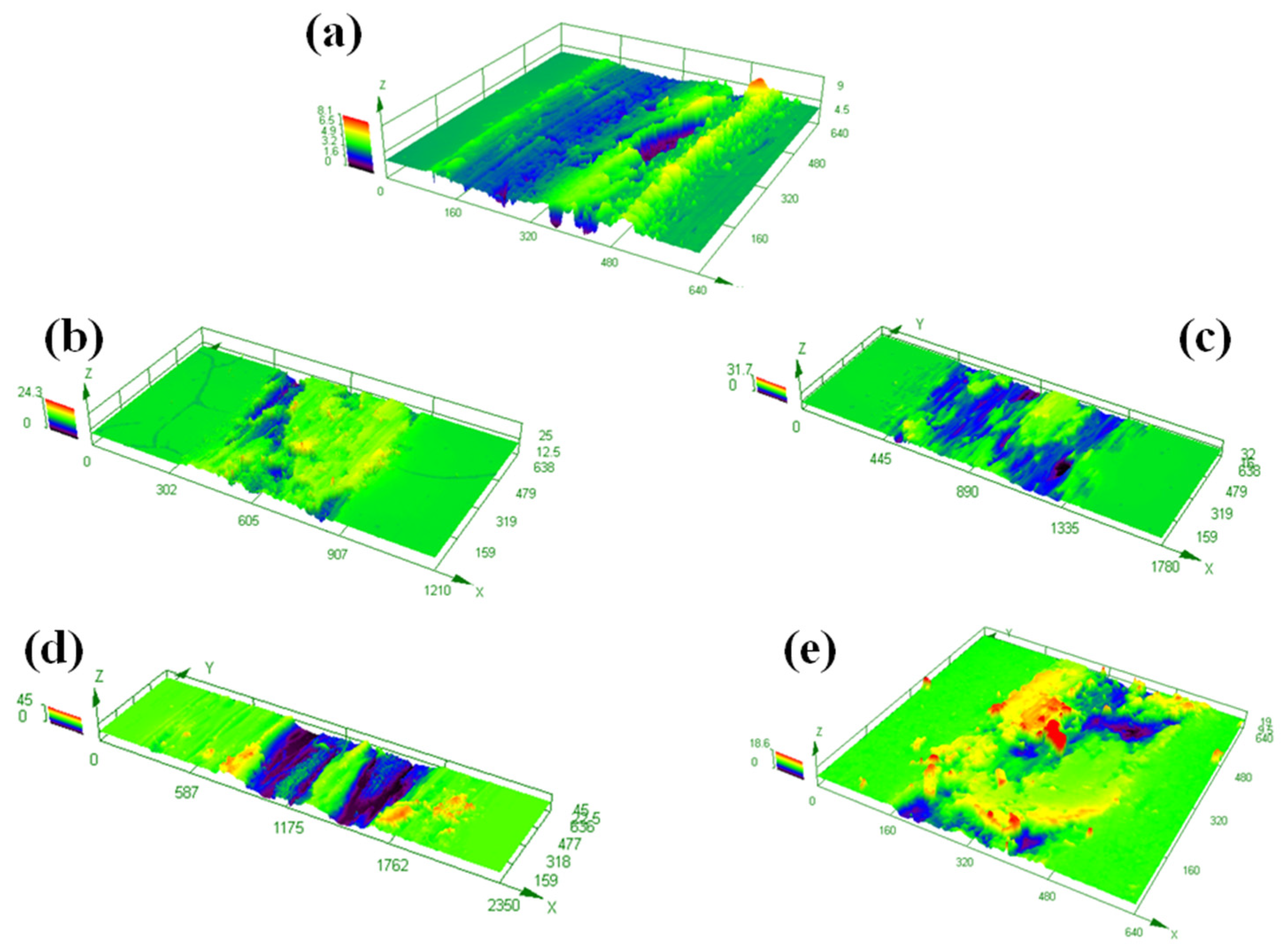
Figure 11 and Figure 12 show the three-dimensional topographies and the wear rate of the friction pair at different temperatures. It was found that the width of the wear scar was low at RT and 800 °C. The width of the wear scar was high at 700 °C. The wear debris accumulated on the wear scar, which decreased the stability at 800 °C.
The CoF was very low for a few hundred seconds, but it could not be sustained for long. The coatings were good in the unworn area. At the same time, there were traces of debris adhesion on the ball; that is, there was a material transfer during the friction process. The CoF was reduced, and a transfer film composed of debris was effectively formed on the ball. There were transferred films whereby the laminar structure of the wear scars was present on the surface of the coatings. This was related to the structure of the h-BN material. The layered structure with a low shear strength significantly reduced the CoF. Therefore, super low friction was achieved at 700 °C. However, the large amount of wear debris accumulation on the worn surface increased the CoF.
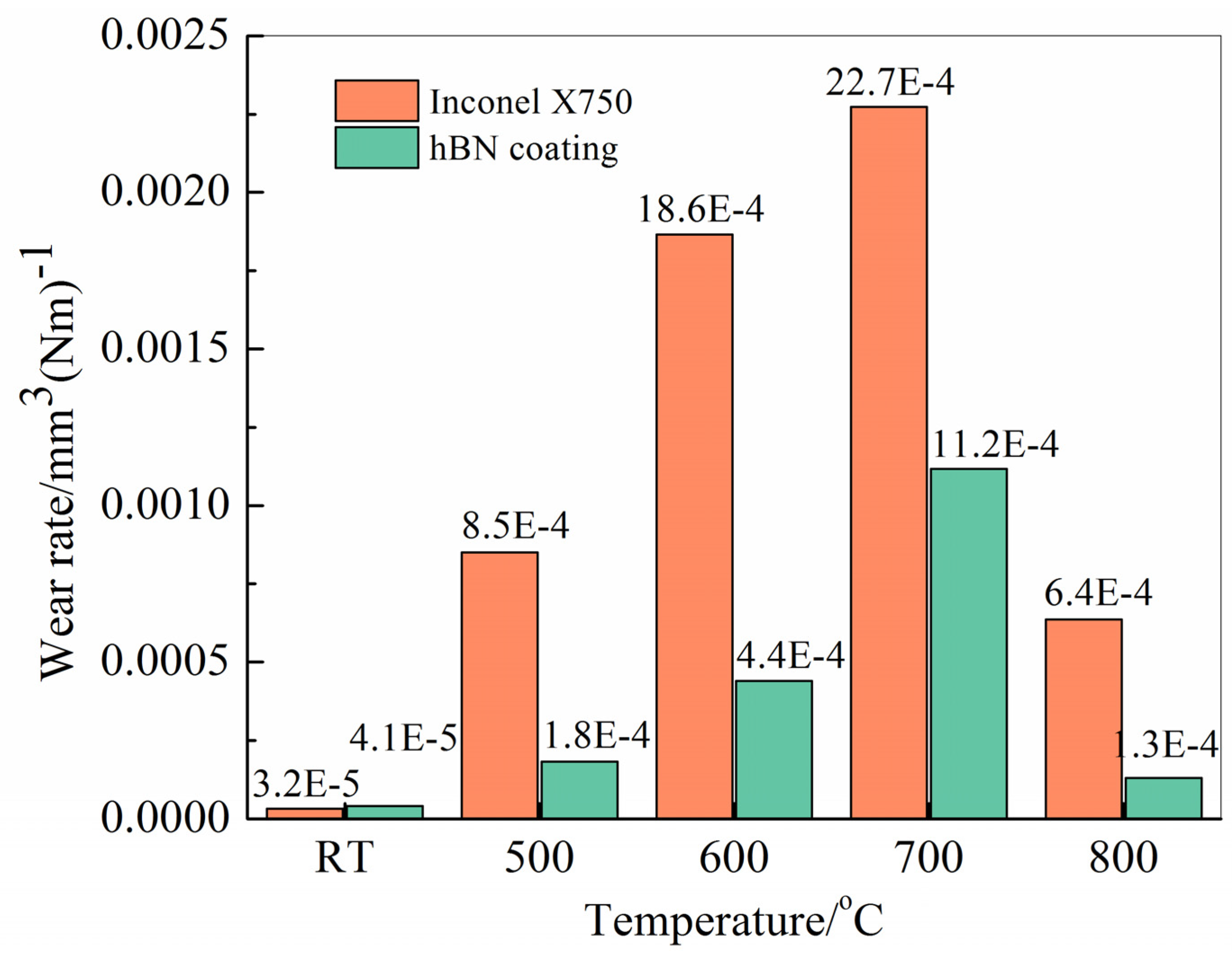
The specific wear rate was calculated compared with that of the uncoated substrate, as shown in Figure 12. It was shown that the trend of the wear rate at different temperatures was almost the same with and without coatings on the substrate. The specific wear rates at RT were the lowest, which were 4.1 × 10⁻⁵ mm3 (Nm)−1 and 3.2 × 10⁻⁵ mm3 (Nm)−1. The wear rate of the h-BN coatings was slightly high. With the increase in temperature, the wear rate gradually increased. The specific wear rate was at its maximum at 700 °C, which was 11.2 × 10⁻⁴ mm3 (Nm)−1 and 22.7 × 10⁻⁴ mm3 (Nm)−1. At 800 °C, the specific wear rates of the h-BN coatings were 1.3 × 10⁻⁴ mm3 (Nm)−1 and 6.4 × 10⁻⁴ mm3 (Nm)−1. The steel was oxidized at a high temperature. However, the alloy had a good high-temperature stability, the hardness was low and it had a high specific wear rate. With the increase in temperature, the hardness of the 750 alloys decreased, and the wear rate increased. This showed that the coating was helpful at reducing the specific wear rate of the substrate at different temperatures, and the wear rate was reduced by 78.8%, 75.5%, 50.7% and 79.7% from 500 °C to 800 °C. The differences in the values of the specific wear ratios of the coatings were large especially at room temperature.
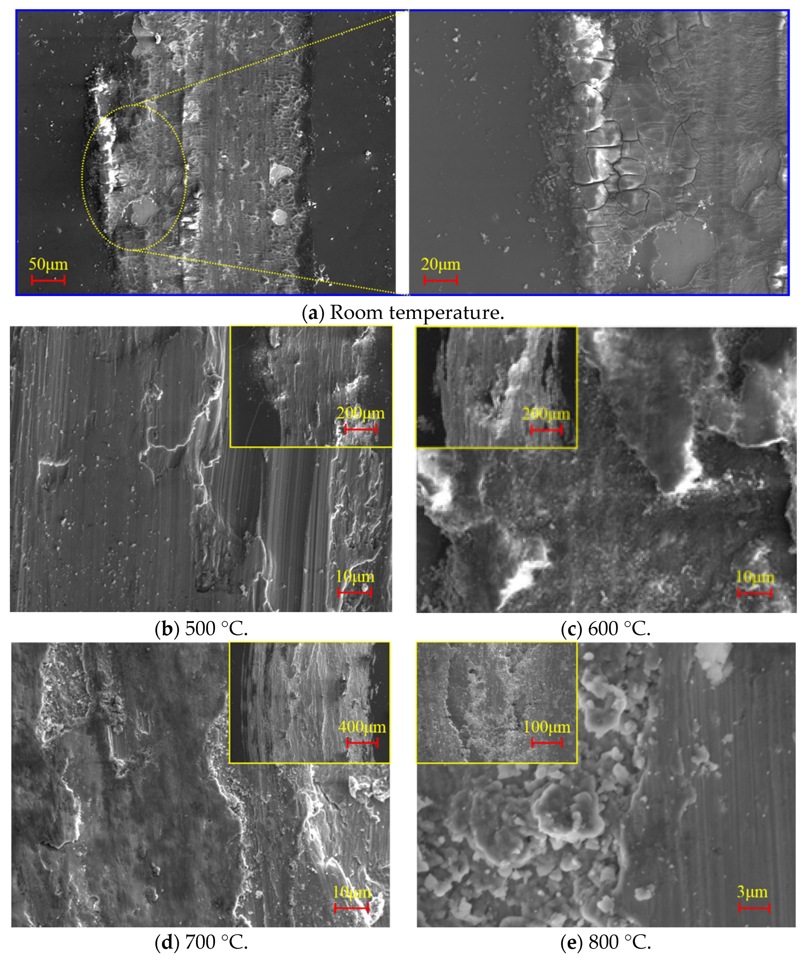
Figure 13 shows the worn surface topography of the friction pair at different temperatures. At RT, the coating was complete, and there were numerous instances of massive spalling and several abrasive particles on the wear marks. There was a difference in hardness between the substrate and the coatings. There may have been local deformation under load. However, the hardness of the substrate at RT was higher than that at a high temperature, so the specific wear rate was low. There were obvious expansion cracks around the wear marks of the coatings at 500 °C, which was not caused by the load. The observation of the coatings showed that there were evenly distributed cracks on the surface of the coatings because there was a relatively obvious thermal expansion of the coatings, and this did not match the thermal expansion rate of the metal substrate. Under thermal stress, it was squeezed and cracked, which resulted in the generation of cracks. The coating was easily flaked off, which reduced the lubrication performance of the coating and led to a high CoF of the coating at 500 °C. At 800 °C, the phenomena were similar in the coating; the cracks of the coating weresmall and the fracture was not formed, which wore the coating out during sliding and constantly resulted in the formation of new wear debris that had a lubrication effect. Therefore, the CoF was not high, but the fluctuation was obvious. At 600 °C and 700 °C, the coating was good, and there were no cracks that appeared in the unworn area. At the same time, there were traces of debris adhesion on the ball; that is, there was a material transfer during the friction process. The CoF was reduced effectively, and it was beneficial to reduce the wear because of the formation of a transfer film composed of debris on the ball.
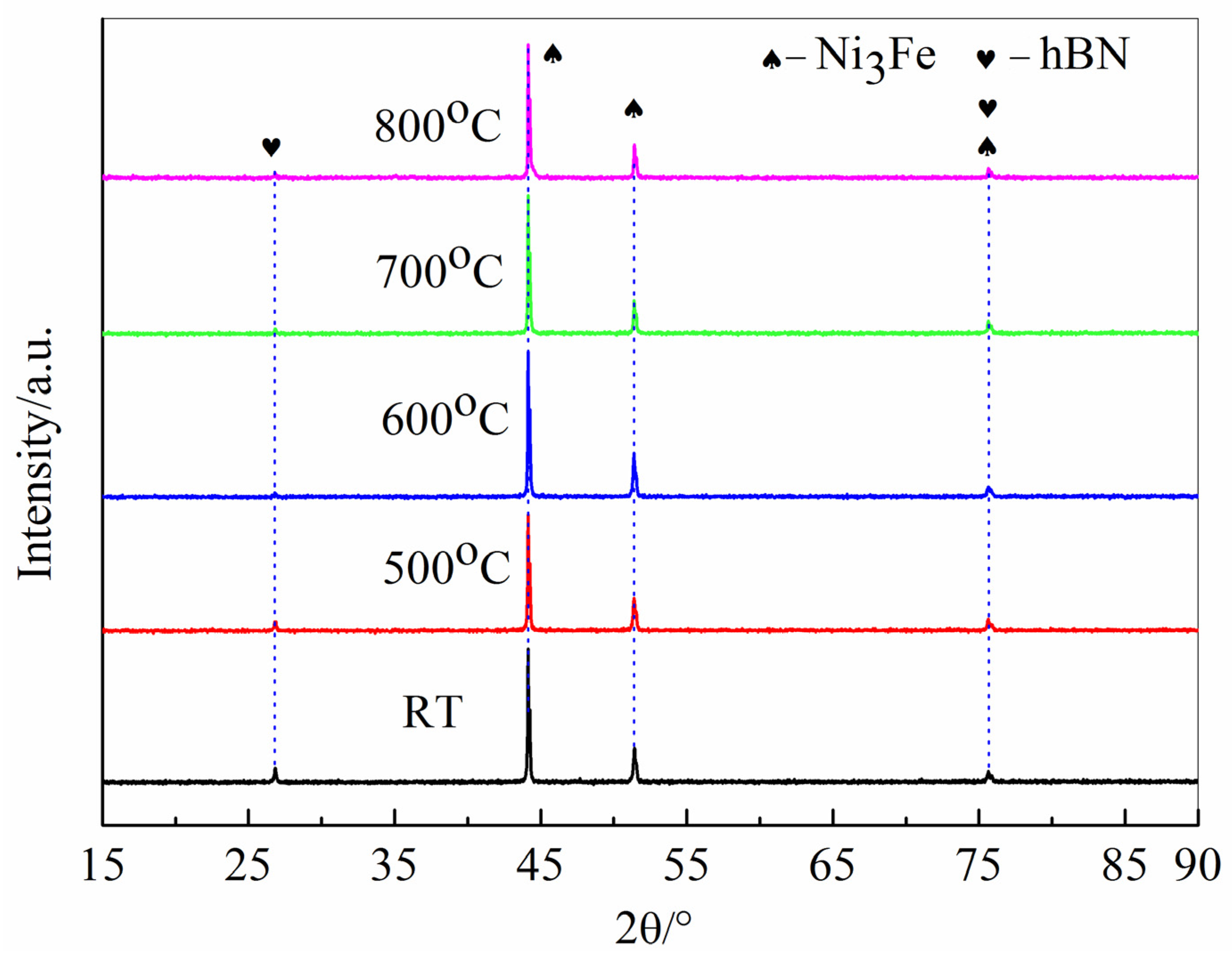
Figure 14 shows the XRD results of the worn surface of alloy. The characteristic peaks of the wear scars were almost the same from room temperature to 800 °C. There were peaks at 44.16°, 51.42° and 75.63°, which were the characteristic peaks of the Ni3Fe phase in the X750 alloy. The main peak of the h-BN phase was at a 2θ value of 26.8° [28], and no characteristic peak of the other materials was found in the spectrum, indicating that the X750 alloy had good thermal stability and oxidation resistance. There were no obvious oxidations of the X750 alloy, and the h-BN coatings also maintained good stability under high temperatures. The substrate was an X750 alloy. There were no iron oxides and B2O3 according to the XRD results. In addition, there were h-BN phases at the wear scar after 1800 s at a high temperature, which resulted in a low CoF. The nature of the layered structure of the h-BN was a hexagonal packed structure composed of boron and nitrogen atoms arranged alternately, which had a special layered structure. This structure has a high stability, so it is widely applied in extreme environments. The wear debris of the h-BN coatings was transferred to the wear scar and formed the transferred films.
The microstructure of the wear marks was characterized by a SEM. Figure 15 shows the worn topography at RT to 800 °C. At RT, there was no effect of thermal expansion. The surface of the coatings was smooth and compact, and there appeared to be a phenomenon of cracking and accumulation under load. The coefficient of the thermal expansion of the metal was higher than that of the coatings. The cracking of the coating was partial under the thermal stress.
The coatings on the wear scar were reduced to wear marks. First, the coatings had a strong ability to bond with the substrate. Although there were cracks appearing in the wear scar, the coatings were still firmly attached to the substrate, the coatings were still maintained after the friction test with a distance of 180 m and the final CoF was around 0.4. At 500 °C, there as a significant expansion in the cracks of the coatings. The coatings were more likely to be peeled off during friction, and there was no coating on the disc. The substrate had deep furrows under the scratches of the ball, while the surface of the coating was relatively flat and the wear scar on the disk was not covered by a coating with a layered structure. The coating partially failed, so the CoF was high. At 600 °C and 700 °C, there were transferred films with laminar structures on the worn surface. There was an obvious compacted layer on the wear scars. The smooth compacted layer was partly worn out at the edge of the compacted layer. Each layer was observed in a stacked stairway. This was the structure of the h-BN. The layered structure with a low shear strength significantly reduced the CoF, and a good bonding ability prevented the peeling of the coating [29,30]. Therefore, a stable super low friction was achieved at 600 °C and 700 °C. At 800 °C, a large number of abrasive particles were accumulated on the wear scars. These lubricating particles reduced the CoF and increased the fluctuation of the friction curve. Based on the above analysis, it was shown that the coatings had an excellent antifriction performance at 600 °C and 700 °C, and the coatings had good high-temperature stability and tribological properties from 500 °C to 800 °C. However, a prominent problem also existed where by the coating fracture caused by the thermal conductivity reduced the lubrication behavior of the coating. The wear debris accumulation also reduced the stability of the friction.
3.7. Tribological Properties of Coatings on Textured Alloy
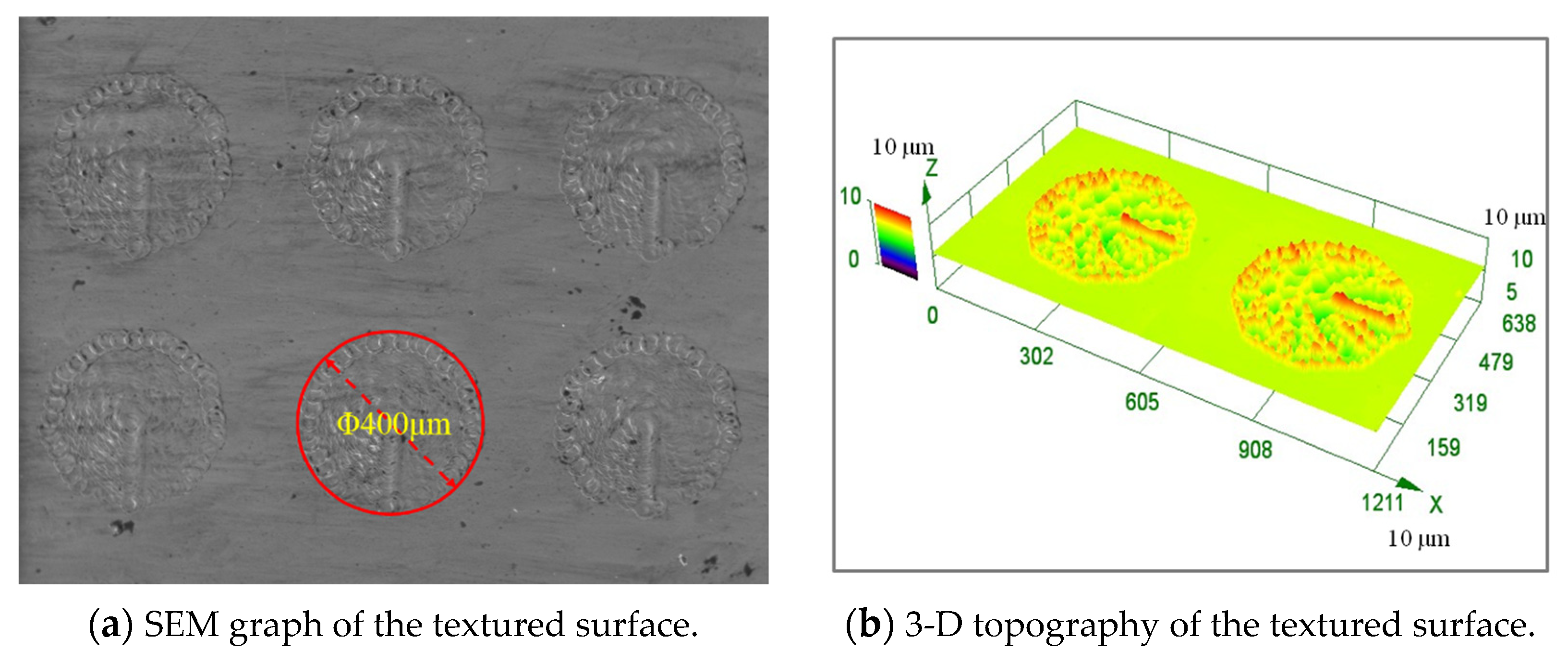
A texture with a circular shape of 400 μm in diameter was prepared on the surface of the Inconel X750 alloy. The surface texture was prepared on the alloy, and then the coating was prepared. The texture was fabricated by the matrix arrangement. The distance of the circle center was 600 μm, and the density of surface texture was 35%. Figure 16 shows a SEM graph of the coating on the textured X750 alloy. The surface of the coating was smooth with a little amount protruding around the circular texture. The purpose of the texture was to store the abrasive chips with lubricating performances, which prevented the lubrication failure of the coating but also avoided the fluctuation in the CoF caused by the accumulation of the abrasive chips [31,32]. Meanwhile, the wear debris was released during the grinding process of the coating and substrate, and it constantly supplemented the consumed lubricating medium, meaning it played the role of long-term lubrication. In view of the phenomenon of the coating cracking observed, we hope that the preparation of texture can play a role in reducing the extrusion cracking caused by thermal expansion and the internal stress of the coating that occurs during sputtering.
Figure 17 shows the CoF of the texture coatings at room temperature and 500–800 °C. Compared with the coating without texture, it was found that the CoF curve at each temperature could maintain a stable CoF without fluctuations after it was reduced to a certain value. The CoF increased at room temperature. However, the CoF remained basically stable after running, and this phenomenon was particularly obvious at 800 °C. This shows that the preparation of texture can promote the stability of the CoF.
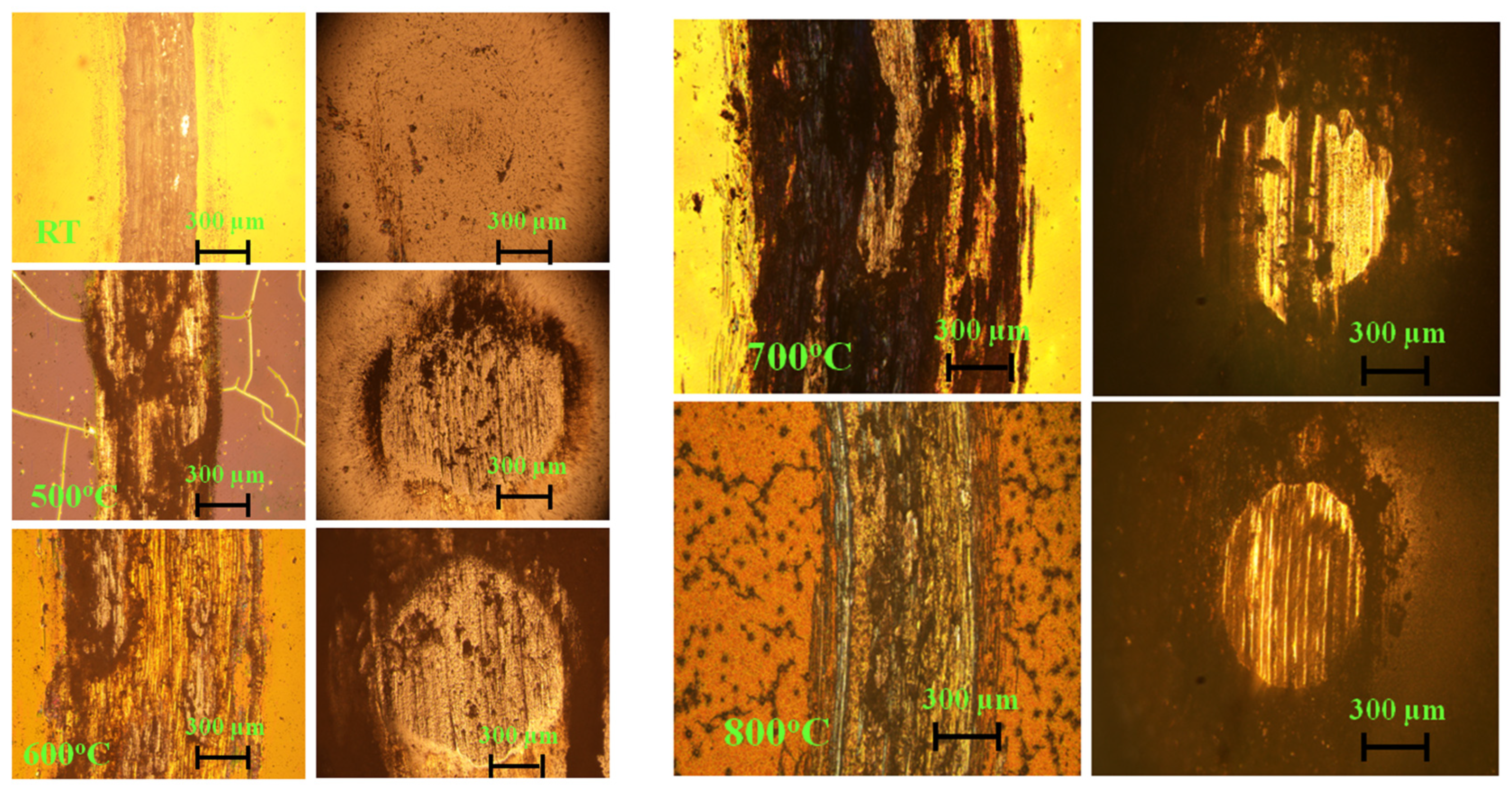
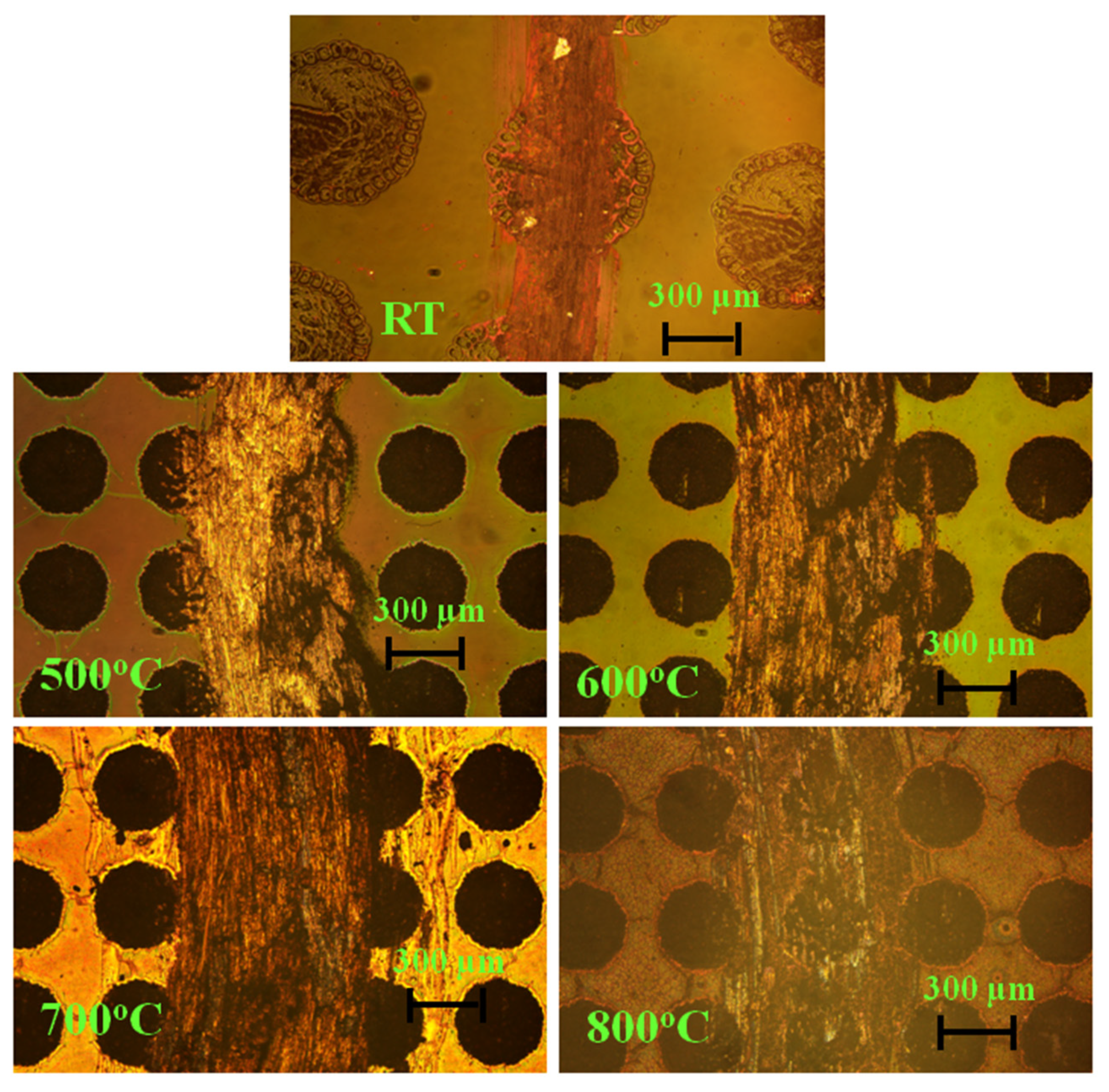
Figure 18 shows the worn surface morphology of the coating on the texted surface. The width of the wear marks was still low at room temperature, and the width was the maximum at 700 °C, while the depth of the wear marks was shallow at 800 °C; additionally, the overall morphology of the texture could be clearly seen, indicating that the texture had not been polished, and the existence of the concave texture stored excess debris, which reduced the CoF and inhibited the violent fluctuation in the friction curve. At the same time, no cracking of the coating was found at any temperature. Compared with the expansion crack of the h-BN coating without texture at 500 °C, it was found that texture could prevent cracking via thermal mechanisms, which is undoubtedly beneficial for the friction behaviors of the coating under high temperatures. Regarding the laser textured alloy with an h-BN coating, the friction pair had low friction that was associated with low wear. The purpose of the texture was to store the abrasive chips with lubricating performances during the friction process and to avoid the fluctuation in the CoF caused by the accumulation of abrasive chips. Meanwhile, the stored wear debris was released during the grinding of the coating and substrate, and it constantly supplemented the consumed lubricating medium, meaning it played the role of long-term lubrication. The recess was almost covered by the debris, especially at 500 °C, 600 °C and 700 °C. The size of the debris may have been microsized, and these wear debris were spread during the friction process. The wear was adhesive wear. There were traces of debris adhesion on the ball and a material transfer during the friction process. The size of the fragments of the coating particles may have been microscale on the surface. The average diameter of the texture was about 400 μm, and the coating particle could be sintered in the textured recesses.
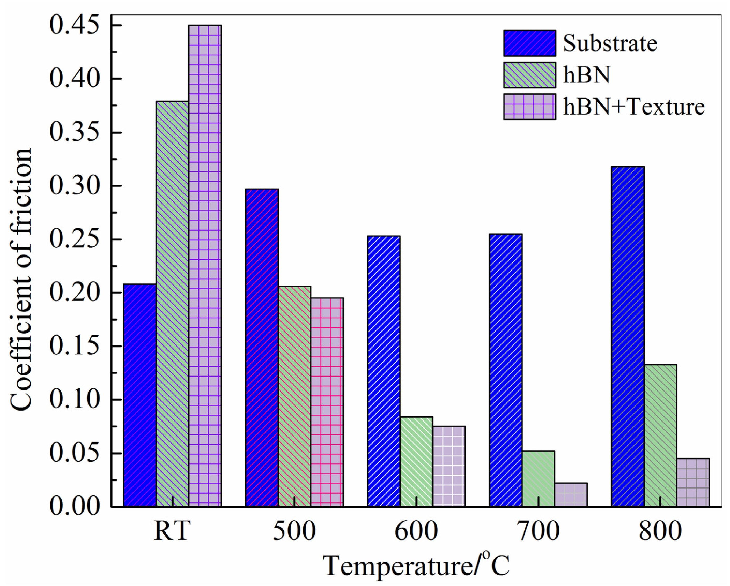
Figure 19 shows the average CoF of the friction pair of the substrate, coating and textured coating. The CoF was calculated at the stable stage, and this CoF was the average CoF. It was shown that the CoF of the substrate without coating was the lowest at room temperature. The CoF became high after the coating was applied, which was attributed to hardness and the generation of flake fragments and reveals that the lubrication performance of the h-BN at room temperature was poor. The existence of texture further increased the CoF. From 500 °C to 800 °C, the CoFs of the alloy were slightly different and were in the range of 0.25–0.32. The coating reduced the CoF. Compared with the substrate, the CoFs decreased by 30.6%, 66.8%, 79.6% and 58.2%. Texture stabilized the fluctuation in the CoF curve, and the CoF further reduced at 700 °C and 800 °C.
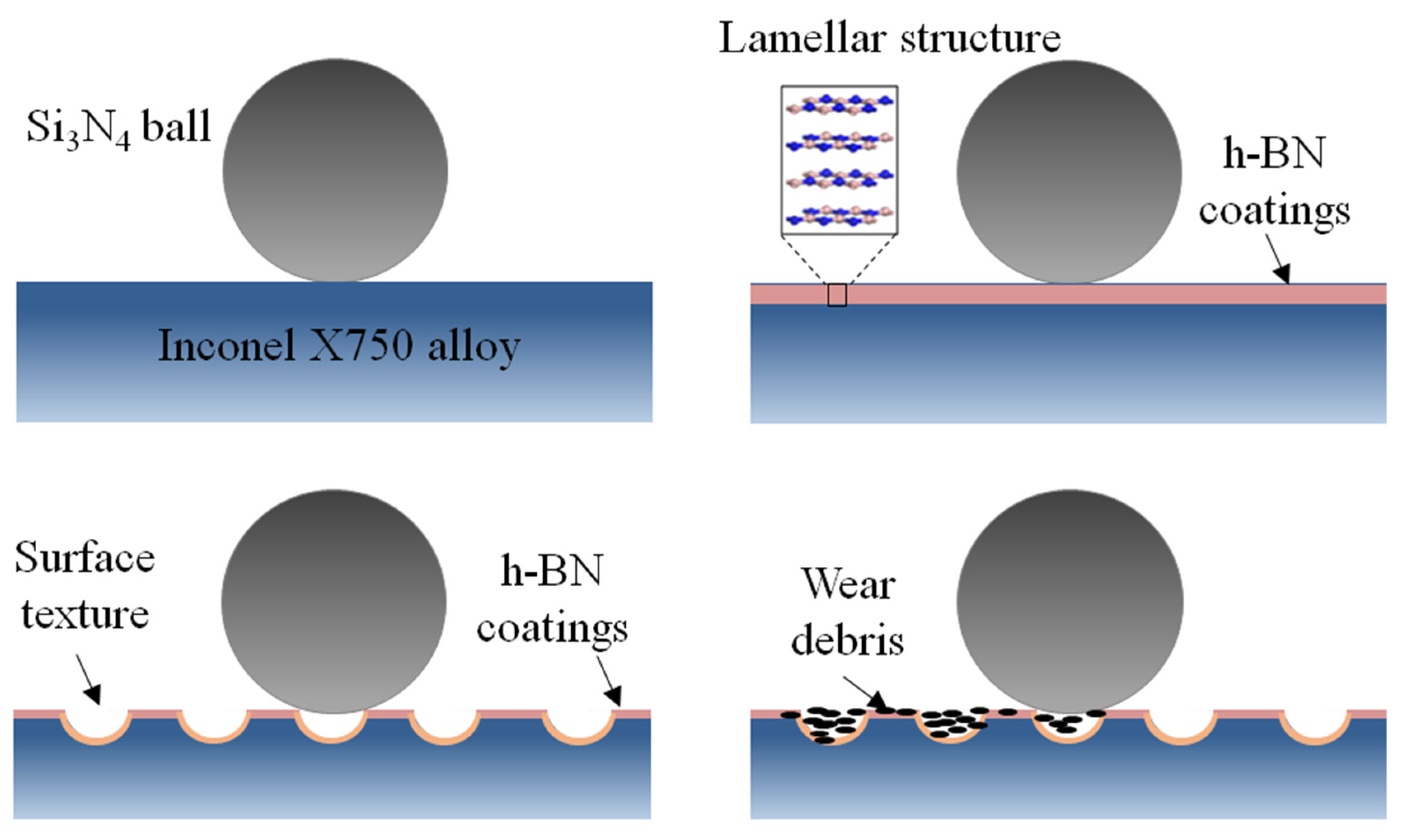
Figure 20 shows schematic diagram of the antifriction mechanism of the coating on the textured X750 alloy. The X750 alloy had good antifriction behaviors, but the CoF was relatively high. Therefore, the h-BN coatings with a lamellar structure were prepared on the alloy. The tribotest results showed that the coating was helpful at enhancing the friction behaviors especially, and high-temperature superlubricity was achieved. However, the CoF fluctuated during sliding. The texture was manufactured to decrease stress and store wear debris, which improved the stability of the high-temperature friction and wear resistance.
4. Conclusions
An Inconel X750 alloy was selected as the substrate, and the tribological properties of the h-BN coating on theX750 alloy were studied at different temperatures. The conclusions are summarized as follows:
- (1)
- The average hardness of the Inconel X750 alloy was217.7 HV. The CoF of the X750 alloy was the lowest at room temperature. The CoF was relatively high at an elevated temperature although the CoF was stable without fluctuation. At a high temperature, the running-in time was low compared with that at room temperature. The CoFs were between 0.25 and 0.32.
- (2)
- The h-BN coating was prepared on the substrate of the X750 alloy with a thickness of 600 nm and Ra of 9.8 nm. The critical load of the bonding strength of the coatings and X750 alloy was about 2 N.
- (3)
- The h-BN coatings had a high CoF at room temperature, but the CoF reduced from 500 °C to 800 °C, and the CoF at the stable stage decreased to 30.6%, 66.8%, 79.6% and 58.2%. The antifriction behavior was obvious at a high temperature. The specific wear rate decreased to 78.8%, 75.5%, 50.7% and 79.7%.
- (4)
- The surface texture was prepared to avoid the cracking problem of the coatings at a high temperature, store the wear debris and reduce the coating peeling and the debris accumulation at a high temperature. The friction curve of the textured coatings at elevated temperatures was stable.
Funding
This work was supported by the Natural Science Basic Research Plan in Shaanxi Province of China (2022JM-251) and the National Natural Science Foundation of China (51675409).
Data Availability Statement
Not applicable.
Conflicts of Interest
The authors declare no conflict of interest.
References
- DellaCorte, C. The effect of counterface on the tribological performance of a high temperature solid lubricant composite from 25 to 650 °C. Surf. Coat. Technol. 1996, 86, 486–492. [Google Scholar] [CrossRef]
- Liu, J.; Liao, R.; Liao, B.; Luo, J.; Bao, K. Mechanical and tribological properties of CrN coated Inconel X750. J. Wuhan Univ. Technol. Mater. Sci. Ed. 2019, 34, 804–810. [Google Scholar] [CrossRef]
- Kumar, R.; Hussainova, I.; Rahmani, R.; Antonov, M. Solid lubrication at high-temperatures—A review. Materials 2022, 15, 1695. [Google Scholar] [CrossRef]
- Liu, X.; Fan, J.; Pu, J.; Lu, Z. Insight into the high-temperature tribological mechanism of VAlTiCrW high entropy alloy film: AlV3O9 from tribochemistry. Friction 2023, 11, 1165–1176. [Google Scholar] [CrossRef]
- Lu, Y.; Wang, X.; Zhang, X.; Lu, X.; Han, W.; Hao, J.; Zhao, T. Tribological behavior of Cu-modified polymer-derived SiBCN ceramics at elevated temperature. Tribol. Int. 2023, 185, 108540. [Google Scholar] [CrossRef]
- Jia, J.; Yang, G.; Zhang, C.; Zhang, S.; Zhang, Y.; Zhang, P. Effects of magnetic ionic liquid as a lubricant on the friction and wear behavior of a steel-steel sliding contact under elevated temperatures. Friction 2021, 9, 61–74. [Google Scholar] [CrossRef] [Green Version]
- Li, Y.; Zhang, S.; Ding, Q.; Feng, D.; Qin, B.; Hu, L. Liquid metal as novel lubricant in a wide temperature range from −10 to 800 °C. Mater. Lett. 2018, 215, 140–143. [Google Scholar] [CrossRef]
- Zeng, Q. High temperature low friction behavior of h-BN coatings against ZrO2. Coatings 2022, 12, 1772. [Google Scholar] [CrossRef]
- Mittal, D.; Singh, D.; Sharma, K. Thermal characteristics and tribological performances of solid lubricants: A mini review. In Advances in Rheology of Materials; Intechopen: London, UK, 2023. [Google Scholar]
- Chen, J.; Chen, J.; Wang, S.; Sun, Q.; Cheng, J.; Yu, Y.; Yang, J. Tribological properties of h-BN matrix solid-lubricating composites under elevated temperatures. Tribol. Int. 2020, 148, 106333. [Google Scholar] [CrossRef]
- Chen, J.; Sun, Q.; Chen, W.; Zhu, S.; Li, W.; Cheng, J.; Yang, J. High-temperature tribological behaviors of ZrO2/h-BN/SiC composite under air and vacuum environments. Tribol. Int. 2021, 154, 106748. [Google Scholar] [CrossRef]
- Lu, X.L.; Liu, X.B.; Yu, P.C.; Zhai, Y.J.; Qiao, S.J.; Wang, M.D.; Wang, Y.G.; Chen, Y. Effects of heat treatment on microstructure and mechanical properties of Ni60/h-BN self-lubricating anti-wear composite coatings on 304 stainless steel by laser cladding. Tribology 2015, 355, 350–358. [Google Scholar] [CrossRef]
- Tyagi, R.; Xiong, D.S.; Li, J.L.; Dai, J. High-temperature friction and wear of Ag/h-BN-containing Ni-based composites against steel. Tribol. Lett. 2010, 40, 181–186. [Google Scholar] [CrossRef]
- Zhang, D.; Cui, X.; Jin, G.; Song, Q.; Yuan, C.; Fang, Y.; Wen, X. Microstructure and tribological performance of laser-cladded Ni60/h-BN coatings on Ti-6Al-4V alloy at high temperature. Tribol. Trans. 2019, 62, 779–788. [Google Scholar] [CrossRef]
- Yuan, S.; Toury, B.; Benayoun, S. Novel chemical process for preparing h-BN solid lubricant coatings on titanium-based substrates for high temperature tribological applications. Surf. Coat. Technol. 2015, 272, 366–372. [Google Scholar] [CrossRef]
- Zhao, Y.; Feng, K.; Yao, C.; Li, Z. Effect of MoO3 on the microstructure and tribological properties of laser-clad Ni60/nanoCu/h-BN/MoO3 composite coatings over wide temperature range. Surf. Coat. Technol. 2020, 387, 125477. [Google Scholar] [CrossRef]
- Cao, J.; Huang, H.; Li, S.; Wu, X.; Yin, Z.; Abbas, Z. Tribological and mechanical behaviors of engine bearing with CuSn10 layer and h-BN/graphite coating prepared by spraying under different temperatures. Tribol. Int. 2020, 152, 106445. [Google Scholar] [CrossRef]
- Raadnui, S.; Mahathanabodee, S.; Tongsri, R.; Morakotjinda, M.; Wila, P. Comparison of dry sliding tribological behavior of SS 316L impregnated with MoS2 vs h-BN solid lubricants: A statistical point of view. Wear 2021, 476, 203676. [Google Scholar] [CrossRef]
- Guimarey, M.J.; Ratwani, C.R.; Xie, K.; Koohgilani, M.; Hadfield, M.; Kamali, A.R.; Abdelkader, A.M. Multifunctional Steel Surface through the Treatment with Graphene and h-BN. Tribol. Int. 2023, 180, 108264. [Google Scholar] [CrossRef]
- Singh, A.K.; Atheaya, D.; Tyagi, R.; Ranjan, V. Friction and wear behavior of atmospheric plasma sprayed NiMoAl-Ag-hBN coatings at elevated temperatures. Surf. Coat. Technol. 2023, 466, 129650. [Google Scholar] [CrossRef]
- Karpov, A.V.; Sychev, A.E.; Boyarchenko, O.D.; Kovalev, I.D.; Belousova, O.V.; Loryan, V.E. Dielectric properties of BN–ZrB2 and BN–ZrO2 based beramics produced by self-propagating high-temperature synthesis. Glass Ceram. 2023, 1–5. [Google Scholar]
- Zhang, H.; Pan, Y.; Zhang, Y.; Lian, G.; Cao, Q.; Que, L. A comparative study on microstructure and tribological characteristics of Mo2FeB2/WC self-lubricating composite coatings with addition of WS2, MoS2, and h-BN. Mater. Des. 2023, 111581. [Google Scholar] [CrossRef]
- Randhawa, K.S.; Prajapati, B. Hygroscopicity Analysis and tribo-mechanical characterizations of conditioned PA6/MoS2/h-BN hybrid composite. J. Inorg. Organomet. Polym. Mater. 2023, 33, 625–635. [Google Scholar] [CrossRef]
- Zeng, Q.; Zhu, J.; Long, Y.; Bouchet, M.I.D.B.; Martin, J.M. Transformation-induced high temperature low friction behaviors of ZrO2-steel system at temperatures up to 900 °C. Mater. Res. Express 2019, 6, 0865f5. [Google Scholar] [CrossRef]
- Zeng, Q.; Qin, L. High temperature anti-friction behaviors of a-Si: H films and counterface material selection. Coatings 2019, 9, 450. [Google Scholar] [CrossRef] [Green Version]
- Zeng, Q.; Chen, T. Superlow friction and oxidation analysis of hydrogenated amorphous silicon films under high temperature. J. Non Cryst. Solids 2018, 493, 73–81. [Google Scholar] [CrossRef]
- Kosinova, M.L.; Rumyantsev, Y.M.; Golubenko, A.N.; Fainer, N.I.; Ayupov, B.M.; Dolgovesova, I.P.; Kolesov, B.A.; Kaichev, V.; Kuznetsov, F.A. Chemical composition of boron carbonitride films grown by plasma-enhanced chemical vapor deposition from trimethylamineborane. Inorg. Mater. 2003, 39, 366–373. [Google Scholar] [CrossRef]
- Jiang, L.; Yuan, X.; Zeng, G.; Wu, Z.; Liang, J.; Chen, X.; Leng, L.; Wang, H.; Wang, H. Metal-free efficient photocatalyst for stable visible-light photocatalytic degradation of refractory pollutant. Appl. Catal. B Environ. 2018, 221, 715–725. [Google Scholar] [CrossRef]
- Zhu, J.; Zeng, Q.; Zhang, B.; Yan, C.; He, W. Elevated-temperature super-lubrication performance analysis of dispersion-strengthened WSN coatings: Experimental research and first-principles calculation. Surf. Coat. Technol. 2021, 406, 126651. [Google Scholar] [CrossRef]
- Zhu, J.; Zeng, Q.; Yan, C.; He, W. WS2 nanopowders as high-temperature lubricants: An experimental and theoretical study. ACS Appl. Nano Mater. 2019, 2, 5604–5613. [Google Scholar] [CrossRef]
- Li, J.; He, Y.; Xiong, D.; Qin, Y.; Chen, J.; Zhu, H. Tribological properties of silver coatings with laser surface textured nickel as interlayer. Tribol. Int. 2016, 100, 178–185. [Google Scholar] [CrossRef]
- Ji, R.; Zhao, Q.; Zhao, L.; Liu, Y.; Jin, H.; Wang, L.; Wu, L.; Xu, Z. Study on high wear resistance surface texture of electrical discharge machining based on a new water-in-oil working fluid. Tribol. Int. 2023, 180, 108218. [Google Scholar] [CrossRef]
Figure 1.
Schematic diagram of the principle of nanoindentation.

Figure 2.
SEM and elemental distributions of Inconel X750 alloy.

Figure 3.
The cross-section image, element and surface roughness of h-BN coatings: (a) EDS, (b) AFM image of coatings and (c) cross-section morphology of coating.
Figure 3.
The cross-section image, element and surface roughness of h-BN coatings: (a) EDS, (b) AFM image of coatings and (c) cross-section morphology of coating.

Figure 4.
The FTIR images of h-BN coatings.

Figure 5.
Nanoindentation loading–unloading curve of h-BN coatings.

Figure 6.
The scratch morphology, corresponding AE signal diagram and critical load of h-BN coatings.
Figure 6.
The scratch morphology, corresponding AE signal diagram and critical load of h-BN coatings.

Figure 7.
The transverse and longitudinal sectional curves of the scratch morphology of h-BN coatings.
Figure 7.
The transverse and longitudinal sectional curves of the scratch morphology of h-BN coatings.

Figure 8.
The CoF curves of X750 alloy at different temperatures.

Figure 9.
The worn surface topography of X750 alloy at different temperatures.

Figure 10.
CoF of coatings.

Figure 11.
Optical images of coatings: (a) RT, (b) 500 °C, (c) 600 °C, (d) 700 °C and (e) 800 °C.

Figure 12.
Specific wear ratio of alloy and coating.

Figure 13.
The topography of wear surface.

Figure 14.
XRD of worn surface of X750 alloy under different temperatures.

Figure 15.
SEM images of the worn surface of coating on X750 alloy.

Figure 16.
SEM and 3D topography of the textured surface.

Figure 17.
CoF of h-BN coating of textured sample.

Figure 18.
Surface topography of the worn textured surface.

Figure 19.
Average CoFs of the substrate, coating and the combination of substrate and coating.

Figure 20.
Schematic diagram of the friction mechanism.


Table 1.
Chemical composition of Inconel X750 alloy.
| Elements | Weight Percent (%) | Atom Percent (%) |
|---|---|---|
| Cr | 14.68 | 13.73 |
| Fe | 6.44 | 5.61 |
| Ni | 70.49 | 58.36 |
| Ti | 2.38 | 2.41 |
| Al | 0.55 | 0.99 |
| Nb | 0.9 | 0.47 |
| Total | 100 | 100 |
Table 2.
Hardness of Inconel X750 alloy.
| Points | 1 | 2 | 3 | 4 | 5 | 6 |
|---|---|---|---|---|---|---|
| Hardness (HV) | 226.4 | 208.5 | 210.9 | 221.2 | 212.1 | 227.3 |
Disclaimer/Publisher’s Note: The statements, opinions and data contained in all publications are solely those of the individual author(s) and contributor(s) and not of MDPI and/or the editor(s). MDPI and/or the editor(s) disclaim responsibility for any injury to people or property resulting from any ideas, methods, instructions or products referred to in the content. |
© 2023 by the author. Licensee MDPI, Basel, Switzerland. This article is an open access article distributed under the terms and conditions of the Creative Commons Attribution (CC BY) license (https://creativecommons.org/licenses/by/4.0/).
Share and Cite
MDPI and ACS Style
Zeng, Q. High-Temperature Superlubricity Performance of h-BN Coating on the Textured Inconel X750 Alloy. Lubricants 2023, 11, 258. https://doi.org/10.3390/lubricants11060258
AMA Style
Zeng Q. High-Temperature Superlubricity Performance of h-BN Coating on the Textured Inconel X750 Alloy. Lubricants. 2023; 11(6):258. https://doi.org/10.3390/lubricants11060258
Chicago/Turabian StyleZeng, Qunfeng. 2023. "High-Temperature Superlubricity Performance of h-BN Coating on the Textured Inconel X750 Alloy" Lubricants 11, no. 6: 258. https://doi.org/10.3390/lubricants11060258
Note that from the first issue of 2016, this journal uses article numbers instead of page numbers. See further details here.