Effect of Laminar, Turbulent and Slip Conditions on the Dynamic Coefficients of a Dry Gas Seal


Abstract
:1. Introduction
2. Method of Analysis
3. Numerical Verification
4. Results and Discussion
4.1. Perturbed Pressure of the Fluid Film in a Dry Gas Seal according to Laminar, Turbulent, and Slip Conditions in the Fluid Film
4.2. Dynamic Coefficients of the Fluid Film in a Dry Gas Seal according to Clearance of the Fluid Film and External Pressure
5. Conclusions
6. Future Work
Author Contributions
Funding
Data Availability Statement
Acknowledgments
Conflicts of Interest
Nomenclature
| h | Film thickness [mm] |
| h0 | Film thickness in equilibrium [mm] |
| Cr | Fluid state coefficients for radial flow |
| Cθ | Fluid state coefficient for circumferential flow |
| Kn | Knudsen number |
| Re | Reynolds number |
| Shape function vector | |
| Element pressure vector [Pa] | |
| Pressure of fluid film [Pa] | |
| Perturbed pressure generated by infinitesimal displacement [Pa/m] | |
| Perturbed pressure generated by infinitesimal velocity [Pa∙s/m] | |
| K | Stiffness matrix [N/m] |
| C | Damping matrix [Ns/m] |
| Slip coefficient; | |
| Gas constant [J/(kg·K)] (: 287 J/(kg·K)) | |
| Temperature [K] | |
| , | Fluid velocity [m/s] |
| Weighting function | |
| Greek symbols | |
| Density [kg/m3] | |
| Arbitrary vector | |
| Viscosity [Pa∙s] | |
| Fixed angular coordinates | |
| Rotating velocity [rad/s] |
References
- Hahn, M.; Park, Y.; Kang, M.; Jun, S.; Jang, G. Effects of laminar, turbulent, and slip conditions in a fluid film on a dry gas seal. Machines 2022, 10, 954. [Google Scholar] [CrossRef]
- Chen, Y.; Wang, Q.; Peng, X.; Li, Y.; Wang, B.; Jin, J. Flow field and sealing performance analysis of compliant foil face gas seal. Adv. Mech. Eng. 2022, 14, 16878132221108488. [Google Scholar] [CrossRef]
- Lu, J. Theoretical analysis and experiment on gas film stiffness with slip flow in a spiral-grooved dry gas seal. Ind. Lubr. Tribol. 2021, 73, 1226–1236. [Google Scholar] [CrossRef]
- Jiang, J.; Peng, X.; Zong, C.; Zhao, W.; Chen, Y.; Li, J. Enhancing film stiffness of spiral groove dry gas seal via shape modification at low speed: Numerical results and experiment. Tribol. Trans. 2019, 62, 931–942. [Google Scholar] [CrossRef]
- Ruan, B. Finite element analysis of the spiral groove gas face seal at the slow speed and the low pressure conditions—Slip flow consideration. Tribol. Trans. 2000, 43, 411–418. [Google Scholar] [CrossRef]
- Chen, Y.; Peng, X.; Jiang, J.; Meng, X.; Li, J. Experimental and theoretical studies of the dynamic behavior of a spiral-groove dry gas seal at high-speeds. Tribol. Int. 2018, 125, 17–26. [Google Scholar] [CrossRef]
- Blasiak, S.; Zahorulko, A.V. A parametric and dynamic analysis of non-contacting gas face seals with modified surfaces. Tribol. Int. 2016, 94, 126–137. [Google Scholar] [CrossRef]
- Liu, Y.; Shen, X.; Xu, W. Numerical analysis of dynamic coefficients for gas film face seals. J. Tribol. 2002, 124, 743–754. [Google Scholar] [CrossRef]
- Teng, L.; Jiang, J.; Peng, X.; Li, J.; Zheng, S.; Zang, C.-P. Study on angular free vibration stability and parameters influence of dry gas seal based on the characteristic equation. Shock Vib. 2022, 2022, 7378999. [Google Scholar] [CrossRef]
- Kim, H.; Jang, G.; Ha, H. A generalized Reynolds equation and its perturbation equations for fluid dynamic bearings with curved surfaces. Tribol. Int. 2012, 50, 6–15. [Google Scholar] [CrossRef]
- Kim, H.; Jang, G.; Lee, S. Complete determination of the dynamic coefficients of coupled journal and thrust bearings considering five degrees of freedom for a general rotor-bearing system. Microsyst. Technol. 2011, 17, 749–759. [Google Scholar] [CrossRef]
- Park, D.-J.; Kim, C.-H.; Jang, G.-H.; Lee, Y.-B. Theoretical considerations of static and dynamic characteristics of air foil thrust bearing with tilt and slip flow. Tribol. Int. 2008, 41, 282–295. [Google Scholar] [CrossRef]
- Jang, G.; Lee, S. Determination of the dynamic coefficients of the coupled journal and thrust bearings by the perturbation method. Tribol. Lett. 2006, 22, 239–246. [Google Scholar] [CrossRef]
- Kou, G.; Li, X.; Wang, Y.; Lin, M.; Tan, C.; Mou, M. Steady performance and dynamic characteristics of a superellipse groove dry gas seal at a high-speed condition. Ind. Lubr. Tribol. 2020, 72, 789–796. [Google Scholar] [CrossRef]
- Rui, C.; Yong, Z.; Jiakang, Y.; Zixi, W. Research on the performance of foil thrust bearings under dynamic disturbances. Tribol. Int. 2022, 174, 107744. [Google Scholar]
- Ng, C.-W.; Pan, C.H.T. A linearized turbulent lubrication theory. J. Basic Eng. 1965, 87, 675–682. [Google Scholar] [CrossRef]
- Taylor, C.M.; Dowson, D. Turbulent lubrication theory—Application to Design. J. Lubr. Technol. 1974, 96, 36–46. [Google Scholar] [CrossRef]
- Fukui, S.; Kaneko, R. Analysis of ultra-thin gas film lubrication based on linearized Boltzmann equation: First report—Derivation of a generalized lubrication equation including thermal creep flow. J. Tribol. 1988, 110, 253. [Google Scholar] [CrossRef]
- Fukui, S.; Kaneko, R. A database for interpolation of poiseuille flow rates for high knudsen number lubrication problems. J. Tribol. 1990, 112, 78–83. [Google Scholar] [CrossRef]
- Ng, C. Fluid dynamic foundation of turbulent lubrication theory. Tribol. Trans. 1964, 7, 311–321. [Google Scholar] [CrossRef]
- Elrod, H.G.; Ng, C.W. A Theory for turbulent fluid films and its application to bearings. J. Lubr. Technol. 1967, 89, 346–362. [Google Scholar] [CrossRef]
- Beskok, A.; Karniadakis, G.E.; Trimmer, W. Rarefaction and compressibility effects in gas microflows. J. Fluids Eng. 1996, 118, 448–456. [Google Scholar] [CrossRef]
- Lu, J.; Ding, X.; Zhang, W. The influence of spiral angle on lift-off speed of face gas seal under start-up. SN Appl. Sci. 2019, 1, 1068. [Google Scholar] [CrossRef]
- Yan, R.; Chen, H.; Zhang, W.; Hong, X.; Bao, X.; Ding, X. Calculation and verification of flow field in supercritical carbon dioxide dry gas seal based on turbulent adiabatic flow model. Tribol. Int. 2022, 165, 107275. [Google Scholar] [CrossRef]
- Faria, M.T.C. An efficient finite element procedure for analysis of high-speed spiral groove gas face seals. J. Tribol. 2001, 123, 205–210. [Google Scholar] [CrossRef]
- Xuexing, D.; Delin, C.; Weizheng, Z.; Shurong, Y. Experiment of frictional vibration performance of the micro-texture of DLC thin film with dry gas seal rings. Tribol. Int. 2020, 147, 106267. [Google Scholar]
- Cao, H.; Liu, Y.; Lin, C.J. Failure analysis and transformation of hydrogen compressor dry gas seal. Appl. Mech. Mater. 2013, 331, 98–101. [Google Scholar] [CrossRef]
- Zardynezhad, S. Achieve successful compressor startup by addressing dry gas seal failure. Hydrocarb. Process 2015, 94, 63–68. [Google Scholar]
- Ruan, B. Numerical modeling of dynamic sealing behaviors of spiral groove gas face seals. J. Tribol. 2002, 124, 186–195. [Google Scholar] [CrossRef]
- Miller, B.A.; Green, I. Semi-analytical dynamic analysis of spiral grooved mechanical gas face seals. J. Tribol. 2003, 125, 403–413. [Google Scholar] [CrossRef]
- Yang, H.X. Theoretical analyses and field applications of gas film lubricated mechanical face seals with her ring bone spiral grooves. Tribol. Trans. 2009, 52, 800–806. [Google Scholar]
- Hong, G.; Kim, K.; Park, Y.; Jang, G. Numerical determination of the frictional coefficients of a fluid film journal bearing considering the elastohydrodynamic lubrication and the asperity contact force. Machines 2022, 10, 494. [Google Scholar] [CrossRef]


| Fluid Condition | Cr | Cθ |
|---|---|---|
| Laminar | 1/12 | 1/12 |
| Turbulent | 1/Gr | 1/Gθ |
| Slip | qp/12 | qp/12 |
| Range of Inverse Kn | c0 | c1 | c2 | c3 |
|---|---|---|---|---|
| 5 < 1/Kn ≤ 1000 | 1.000 | 6.097 | 6.391 | −12.812 |
| 0.15 < 1/Kn ≤ 5 | 0.831 | 7.505 | 0.939 | −0.058 |
| 1/Kn ≤ 0.15 | −13.375 | 12.640 | 0.099 | 0.0004 |
| Opening Force [N] | Stiffness Coefficient (Kzz) [N/m] | Damping Coefficient (Czz) [Ns/m] | |
|---|---|---|---|
| Present analysis | 4840 | 1.34 × 10⁹ | 4.20 × 10⁴ |
| Faria’s result [25] | 4837 | 1.32 × 10⁹ | 4.23 × 10⁴ |
| Parameter | Value |
|---|---|
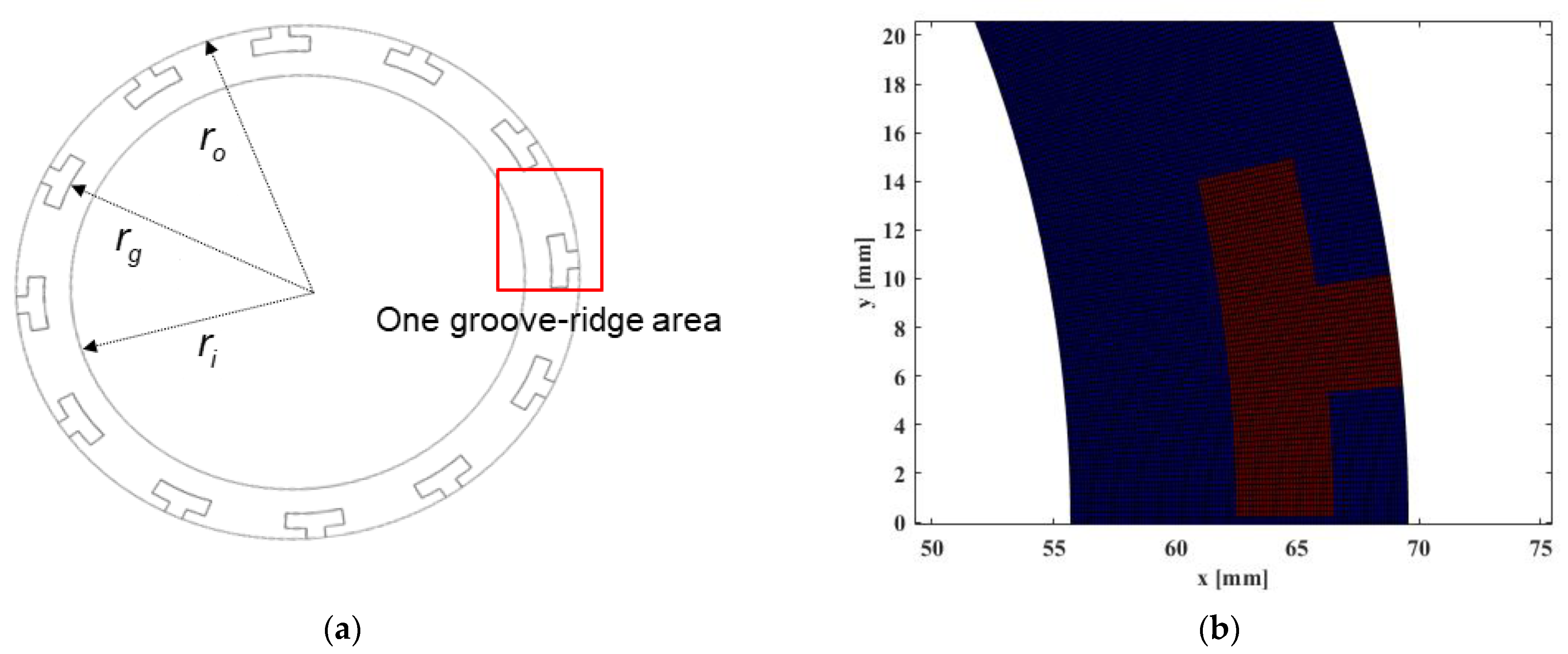
| Outer radius, ro [mm] | 69.5 |
| Groove radius, rg [mm] | 62.4 |
| Internal radius, ri [mm] | 55.7 |
| Groove number | 18 |
| Ratio of ridge and groove | 0.65 |
| Groove depth [mm] | 0.01 |
| Clearance [μm] | Stiffness Coefficients (K) | |||||||||||
|---|---|---|---|---|---|---|---|---|---|---|---|---|
| Kzz [×107 N/m] | Difference [%] | Kθxθx [×105 Nm/rad] | Difference [%] | |||||||||
| L | LT | LTS | LT–L | LTS–L | LTS–LT | L | LT | LTS | LT–L | LTS–L | LTS–LT | |
| 2.5 | 74.86 | 249.56 | 248.63 | 233.4 | 232.1 | −0.4 | 11.48 | 46.36 | 46.20 | 303.9 | 302.6 | −0.3 |
| 3.0 | 63.17 | 196.07 | 195.42 | 210.4 | 209.4 | −0.3 | 9.31 | 35.61 | 35.50 | 282.6 | 281.4 | −0.3 |
| 3.5 | 55.34 | 155.19 | 154.73 | 180.4 | 179.6 | −0.3 | 7.91 | 27.44 | 27.37 | 246.8 | 245.9 | −0.3 |
| 4.0 | 49.92 | 124.35 | 124.03 | 149.1 | 148.5 | −0.3 | 6.97 | 21.32 | 21.27 | 205.7 | 205.0 | −0.2 |
| Clearance [μm] | Damping Coefficients (C) | |||||||||||
|---|---|---|---|---|---|---|---|---|---|---|---|---|
| Czz [×104 Ns/m] | Difference [%] | Cθxθx [×10 Nsm/rad] | Difference [%] | |||||||||
| L | LT | LTS | LT–L | LTS–L | LTS–LT | L | LT | LTS | LT–L | LTS–L | LTS–LT | |
| 2.5 | 27.75 | 34.26 | 34.19 | 23.4 | 23.2 | −0.2 | 53.34 | 66.57 | 66.44 | 24.8 | 24.6 | −0.2 |
| 3.0 | 17.99 | 23.90 | 23.86 | 32.8 | 32.6 | −0.2 | 34.99 | 47.35 | 47.27 | 35.3 | 35.1 | −0.2 |
| 3.5 | 12.58 | 18.05 | 18.02 | 43.4 | 43.2 | −0.2 | 24.69 | 36.30 | 36.25 | 47.1 | 46.8 | −0.1 |
| 4.0 | 9.27 | 14.31 | 14.28 | 54.3 | 54.1 | −0.2 | 18.31 | 29.12 | 29.08 | 59.0 | 58.8 | −0.1 |
Disclaimer/Publisher’s Note: The statements, opinions and data contained in all publications are solely those of the individual author(s) and contributor(s) and not of MDPI and/or the editor(s). MDPI and/or the editor(s) disclaim responsibility for any injury to people or property resulting from any ideas, methods, instructions or products referred to in the content. |
© 2023 by the authors. Licensee MDPI, Basel, Switzerland. This article is an open access article distributed under the terms and conditions of the Creative Commons Attribution (CC BY) license (https://creativecommons.org/licenses/by/4.0/).
Share and Cite
Park, Y.; Hahn, M.; Jang, G. Effect of Laminar, Turbulent and Slip Conditions on the Dynamic Coefficients of a Dry Gas Seal. Lubricants 2023, 11, 98. https://doi.org/10.3390/lubricants11030098
Park Y, Hahn M, Jang G. Effect of Laminar, Turbulent and Slip Conditions on the Dynamic Coefficients of a Dry Gas Seal. Lubricants. 2023; 11(3):98. https://doi.org/10.3390/lubricants11030098
Chicago/Turabian StylePark, Youngjun, Mibbeum Hahn, and Gunhee Jang. 2023. "Effect of Laminar, Turbulent and Slip Conditions on the Dynamic Coefficients of a Dry Gas Seal" Lubricants 11, no. 3: 98. https://doi.org/10.3390/lubricants11030098